EP2330660A1 - Rechargeable battery - Google Patents
Rechargeable battery Download PDFInfo
- Publication number
- EP2330660A1 EP2330660A1 EP10193949A EP10193949A EP2330660A1 EP 2330660 A1 EP2330660 A1 EP 2330660A1 EP 10193949 A EP10193949 A EP 10193949A EP 10193949 A EP10193949 A EP 10193949A EP 2330660 A1 EP2330660 A1 EP 2330660A1
- Authority
- EP
- European Patent Office
- Prior art keywords
- electrode assembly
- electrode
- rechargeable battery
- metal plate
- uncoated region
- Prior art date
- Legal status (The legal status is an assumption and is not a legal conclusion. Google has not performed a legal analysis and makes no representation as to the accuracy of the status listed.)
- Granted
Links
- 229910052751 metal Inorganic materials 0.000 claims abstract description 57
- 239000002184 metal Substances 0.000 claims abstract description 57
- 239000000463 material Substances 0.000 claims description 5
- RYGMFSIKBFXOCR-UHFFFAOYSA-N Copper Chemical compound [Cu] RYGMFSIKBFXOCR-UHFFFAOYSA-N 0.000 claims description 4
- 229910052802 copper Inorganic materials 0.000 claims description 4
- 239000010949 copper Substances 0.000 claims description 4
- 239000002245 particle Substances 0.000 description 4
- 239000011149 active material Substances 0.000 description 3
- 238000007599 discharging Methods 0.000 description 3
- 238000010304 firing Methods 0.000 description 3
- 239000002861 polymer material Substances 0.000 description 3
- 229910000881 Cu alloy Inorganic materials 0.000 description 2
- 239000011248 coating agent Substances 0.000 description 2
- 238000000576 coating method Methods 0.000 description 2
- 230000000052 comparative effect Effects 0.000 description 2
- 239000003792 electrolyte Substances 0.000 description 2
- 239000008151 electrolyte solution Substances 0.000 description 2
- 238000004880 explosion Methods 0.000 description 2
- 238000002347 injection Methods 0.000 description 2
- 239000007924 injection Substances 0.000 description 2
- 238000007789 sealing Methods 0.000 description 2
- 238000004804 winding Methods 0.000 description 2
- 241000743339 Agrostis Species 0.000 description 1
- WHXSMMKQMYFTQS-UHFFFAOYSA-N Lithium Chemical compound [Li] WHXSMMKQMYFTQS-UHFFFAOYSA-N 0.000 description 1
- HBBGRARXTFLTSG-UHFFFAOYSA-N Lithium ion Chemical compound [Li+] HBBGRARXTFLTSG-UHFFFAOYSA-N 0.000 description 1
- 230000008878 coupling Effects 0.000 description 1
- 238000010168 coupling process Methods 0.000 description 1
- 238000005859 coupling reaction Methods 0.000 description 1
- 239000007772 electrode material Substances 0.000 description 1
- 238000005516 engineering process Methods 0.000 description 1
- 239000011888 foil Substances 0.000 description 1
- 230000020169 heat generation Effects 0.000 description 1
- 238000009413 insulation Methods 0.000 description 1
- 239000012212 insulator Substances 0.000 description 1
- 238000010030 laminating Methods 0.000 description 1
- 229910052744 lithium Inorganic materials 0.000 description 1
- 229910001416 lithium ion Inorganic materials 0.000 description 1
- 230000004048 modification Effects 0.000 description 1
- 238000012986 modification Methods 0.000 description 1
- 239000011255 nonaqueous electrolyte Substances 0.000 description 1
- 230000000149 penetrating effect Effects 0.000 description 1
- 230000035515 penetration Effects 0.000 description 1
- 229920000642 polymer Polymers 0.000 description 1
Images


Classifications
-
- H—ELECTRICITY
- H01—ELECTRIC ELEMENTS
- H01M—PROCESSES OR MEANS, e.g. BATTERIES, FOR THE DIRECT CONVERSION OF CHEMICAL ENERGY INTO ELECTRICAL ENERGY
- H01M50/00—Constructional details or processes of manufacture of the non-active parts of electrochemical cells other than fuel cells, e.g. hybrid cells
- H01M50/10—Primary casings, jackets or wrappings of a single cell or a single battery
- H01M50/147—Lids or covers
- H01M50/148—Lids or covers characterised by their shape
- H01M50/15—Lids or covers characterised by their shape for prismatic or rectangular cells
-
- H—ELECTRICITY
- H01—ELECTRIC ELEMENTS
- H01M—PROCESSES OR MEANS, e.g. BATTERIES, FOR THE DIRECT CONVERSION OF CHEMICAL ENERGY INTO ELECTRICAL ENERGY
- H01M50/00—Constructional details or processes of manufacture of the non-active parts of electrochemical cells other than fuel cells, e.g. hybrid cells
- H01M50/50—Current conducting connections for cells or batteries
- H01M50/572—Means for preventing undesired use or discharge
- H01M50/574—Devices or arrangements for the interruption of current
- H01M50/578—Devices or arrangements for the interruption of current in response to pressure
-
- H—ELECTRICITY
- H01—ELECTRIC ELEMENTS
- H01M—PROCESSES OR MEANS, e.g. BATTERIES, FOR THE DIRECT CONVERSION OF CHEMICAL ENERGY INTO ELECTRICAL ENERGY
- H01M50/00—Constructional details or processes of manufacture of the non-active parts of electrochemical cells other than fuel cells, e.g. hybrid cells
- H01M50/10—Primary casings, jackets or wrappings of a single cell or a single battery
- H01M50/102—Primary casings, jackets or wrappings of a single cell or a single battery characterised by their shape or physical structure
- H01M50/103—Primary casings, jackets or wrappings of a single cell or a single battery characterised by their shape or physical structure prismatic or rectangular
-
- H—ELECTRICITY
- H01—ELECTRIC ELEMENTS
- H01M—PROCESSES OR MEANS, e.g. BATTERIES, FOR THE DIRECT CONVERSION OF CHEMICAL ENERGY INTO ELECTRICAL ENERGY
- H01M50/00—Constructional details or processes of manufacture of the non-active parts of electrochemical cells other than fuel cells, e.g. hybrid cells
- H01M50/40—Separators; Membranes; Diaphragms; Spacing elements inside cells
- H01M50/463—Separators, membranes or diaphragms characterised by their shape
- H01M50/469—Separators, membranes or diaphragms characterised by their shape tubular or cylindrical
-
- H—ELECTRICITY
- H01—ELECTRIC ELEMENTS
- H01M—PROCESSES OR MEANS, e.g. BATTERIES, FOR THE DIRECT CONVERSION OF CHEMICAL ENERGY INTO ELECTRICAL ENERGY
- H01M50/00—Constructional details or processes of manufacture of the non-active parts of electrochemical cells other than fuel cells, e.g. hybrid cells
- H01M50/50—Current conducting connections for cells or batteries
- H01M50/531—Electrode connections inside a battery casing
- H01M50/536—Electrode connections inside a battery casing characterised by the method of fixing the leads to the electrodes, e.g. by welding
-
- H—ELECTRICITY
- H01—ELECTRIC ELEMENTS
- H01M—PROCESSES OR MEANS, e.g. BATTERIES, FOR THE DIRECT CONVERSION OF CHEMICAL ENERGY INTO ELECTRICAL ENERGY
- H01M50/00—Constructional details or processes of manufacture of the non-active parts of electrochemical cells other than fuel cells, e.g. hybrid cells
- H01M50/50—Current conducting connections for cells or batteries
- H01M50/531—Electrode connections inside a battery casing
- H01M50/538—Connection of several leads or tabs of wound or folded electrode stacks
-
- H—ELECTRICITY
- H01—ELECTRIC ELEMENTS
- H01M—PROCESSES OR MEANS, e.g. BATTERIES, FOR THE DIRECT CONVERSION OF CHEMICAL ENERGY INTO ELECTRICAL ENERGY
- H01M50/00—Constructional details or processes of manufacture of the non-active parts of electrochemical cells other than fuel cells, e.g. hybrid cells
- H01M50/50—Current conducting connections for cells or batteries
- H01M50/572—Means for preventing undesired use or discharge
- H01M50/584—Means for preventing undesired use or discharge for preventing incorrect connections inside or outside the batteries
- H01M50/586—Means for preventing undesired use or discharge for preventing incorrect connections inside or outside the batteries inside the batteries, e.g. incorrect connections of electrodes
-
- Y—GENERAL TAGGING OF NEW TECHNOLOGICAL DEVELOPMENTS; GENERAL TAGGING OF CROSS-SECTIONAL TECHNOLOGIES SPANNING OVER SEVERAL SECTIONS OF THE IPC; TECHNICAL SUBJECTS COVERED BY FORMER USPC CROSS-REFERENCE ART COLLECTIONS [XRACs] AND DIGESTS
- Y02—TECHNOLOGIES OR APPLICATIONS FOR MITIGATION OR ADAPTATION AGAINST CLIMATE CHANGE
- Y02E—REDUCTION OF GREENHOUSE GAS [GHG] EMISSIONS, RELATED TO ENERGY GENERATION, TRANSMISSION OR DISTRIBUTION
- Y02E60/00—Enabling technologies; Technologies with a potential or indirect contribution to GHG emissions mitigation
- Y02E60/10—Energy storage using batteries
Definitions
- This disclosure relates to a rechargeable battery. More particularly, this disclosure generally relates to a rechargeable battery including a safety device.
- a rechargeable battery can be recharged and discharged unlike a primary battery that cannot be recharged.
- a rechargeable battery with low capacity is used for a small portable electronic device such as a mobile phone, a laptop computer, and a camcorder, while a rechargeable battery with large capacity is used as a power source for driving a motor such as for a hybrid vehicle.
- the aforementioned rechargeable battery with large capacity is formed into a battery module with large capacity by coupling a plurality of these rechargeable batteries in series or in parallel in order to use it to drive a device, for example, a motor such as an electric vehicle requiring a large amount of electric power.
- the rechargeable battery may be fabricated to have a cylindrical shape, a prismatic shape, and the like.
- a prismatic rechargeable battery includes an electrode assembly including positive and negative electrodes and a separator therebetween, a case having a space in which the electrode assembly is located, a cap plate closing and sealing the case, and a terminal electrically connected to the electrode assembly and protruded through the cap plate out of the case.
- the short circuit may sharply increase a temperature inside the rechargeable battery and provide a danger of firing or exploding it.
- An exemplary embodiment of the present invention provides a rechargeable having improved safety by solving the aforementioned problem.
- a rechargeable battery comprising n electrode assembly having a first electrode, a second electrode and a separator interposed between the first and the second electrodes, wherein the first electrode comprises a first uncoated region and the second electrode comprises a second uncoated region, case for mounting the electrode assembly therein, and cap plate for covering an opening of the case.
- a metal plate is further provided electrically connected to the first uncoated region of the electrode assembly and is provided between the case and the electrode assembly.
- the metal plate prevents firing and explosion of a rechargeable battery due to the establishment of an internal short circuit upon intrusion of conductive foreign particles and thereby improves the safety of the battery.
- the case is preferably electrically connected to the second electrode and insulated from the metal plate and wherein the metal plate is adapted to form a short-circuit between the first electrode and the case.
- the metal plate may have a first portion arranged in parallel to a main portion of the electrode assembly and a second portion arranged in parallel to the first uncoated region of the first electrode.
- the second portion can be easily welded to the uncoated region of the first electrode and can prevent the negative uncoated region of the first electrode from being shaken due to external impact or vibration.
- the second portion supports the negative uncoated region of the first electrode.
- the outer layer of the electrode assembly is preferably formed electrically insulating or wherein an insulating film is provided between the main portion of the electrode assembly and the first portion of the metal plate.
- the insulating film prevents the electrode assembly from being electrically connected to the metal plate.
- the insulating film is preferably adhered to the first portion of the metal plate.
- the metal plate may be provided with a third portion connecting the first portion with the second portion.
- the third portion may be angled with respect to the first portion and/or the second portion of the metal plate.
- the first electrode is preferably a negative electrode of the electrode assembly and the second electrode is a positive electrode of the electrode assembly.
- the metal plate may comprise or consist of the same material as the first electrode.
- the first electrode material preferably comprises copper.
- a first metal plate is formed on one side of the electrode assembly and a second metal plate is formed on the opposing side of the electrode assembly and being connected to the first uncoated region.
- a main portion of the electrode assembly may have a first thickness and the first uncoated region has a second thickness being smaller than the first thickness.
- a surface area of the first portion of the metal plate facing the main portion of the electrode assembly is preferably the same or less than the surface area of the main portion of the electrode assembly facing the metal plate.
- a surface area of the first portion of the metal plate facing the main portion of the electrode assembly is preferably at least 60% of the surface area of the main portion of the electrode assembly facing the metal plate, even more preferably at least 80%.
- the metal plate may be adhered to the electrode assembly or the insulating film may be adhered to the electrode assembly.
- FIG. 1 is the perspective view of a rechargeable battery according to the first embodiment, while FIG. 2 is a cross-sectional view of the rechargeable battery cut along the line II - II .
- a rechargeable battery 100 includes an electrode assembly 10 fabricated by winding positive and negative electrodes 11 and 12 and a separator 13 disposed therebetween, a case housing the electrode assembly 10, and a cap assembly 20 combined with the case 34.
- the electrode assembly 10 after winding comprises flat parts 10a formed at their front and back sides as shown in Fig. 3 and curved parts 10b at their top and bottom faces.
- the curved parts 10b connect the front and back flat parts 10a.
- a rechargeable battery 100 will be illustrated as a prismatic lithium ion secondary battery.
- this disclosure of the present invention is not limited thereto but may be applied to various battery types such as a lithium polymer battery, a cylindrical battery, or the like.
- the positive and negative electrodes 11 and 12 may include a coating region prepared by coating a current collector made of a thin metal foil plate with an active material and uncoated regions 11a and 12a not coated with the active material.
- the positive uncoated region 11a is formed at one end of the positive electrode 11 along the length direction, while the negative uncoated region 12a is formed at the other end of the negative electrode 12 along the length direction.
- the positive and negative electrodes 11 and 12 and the separator 13 therebetween as an insulator were spiral-wound.
- the electrode assembly 10 may be supported outside by a finishing tape (not shown) to support the shape.
- this disclosure is not limited thereto but may include the electrode assembly 10 prepared by laminating a plurality of positive and negative electrodes and a separator therebetween.
- the case 34 has a cuboid shape at large and an opening at one side.
- the cap assembly 20 includes a cap plate 30 covering the opening of the case 34, a positive terminal 21 protruded out of the cap plate 30 and electrically connected to the positive electrode 11, a negative terminal 22 protruded out of the cap plate 30 and electrically connected to the negative electrode, and a vent member 39 equipped with a notch 39a that can be broken depending on a predetermined internal pressure.
- the cap plate 30 is made of a thin plate and includes an electrolyte injection opening 27 for implanting an electrolyte solution at one side and a sealing cover 38 for the electrolyte injection opening 27.
- the terminals 21 and 22 include a positive terminal 21 and a negative terminal 22.
- the gasket 25 is fit into the terminal hole. In other words, it is made of two pieces and respectively positioned closely adjacent to top and bottom of the terminal hole.
- the terminals 21 and 22 have a circular cylinder shape and a screw thread on the external circumference where a nut can be combined together. They are combined with a nut 29 on top. They may further include a washer 24 between the nut 29 and the gasket 25 to buffer their combining strength. On the other hand, the terminals 21 and 22 have terminal flanges 21a and 22a at the bottom to support themselves.
- a lower insulating member 26 for insulation.
- the terminals 21 and 22 are inserted into the lower insulating member 26.
- the terminal flanges 21a and 22a are welded with a lead member 32 electrically connected to a positive electrode 11 or negative electrode 12.
- the terminal flanges 21a and 22a and the lead member 32 are fit into a hole formed at the bottom of the lower insulating member 26.
- a metal supporting plate 40 is welded into the negative uncoated region 12a to externally support the electrode assembly 10.
- FIG. 3 is the exploded perspective view of an electrode assembly and a metal supporting plate according to the first embodiment of the present invention.
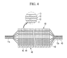
- FIG. 4 is the horizontally cross-sectional view of the above members shown in FIG. 3 when combined.
- the metal supporting plate 40 includes a first or flat part 41 facing the front side of the electrode assembly 10, preferably the front flat part 10a of the electrode assembly, a curving slope or third part 42 formed at one end of the flat part 41 and curved toward an electrode assembly, and a junction or second part 43 formed at the end of the curving slope part 42 and electrically connected to the negative uncoated region 12a.
- the metal supporting plate 40 is welded with the negative uncoated region 12a at the junction part 43 and made of the same material as the negative uncoated region 12a. According to the embodiment of the present, the metal supporting plate 40 is made of copper or copper alloy.
- An insulating film 45 is disposed between, preferably only between the flat part 41 and the electrode assembly.
- the insulating film 45 is attached to the flat part 41 and prevents the electrode assembly 10 from being electrically connected to the flat part 41. It is made of a polymer material not reacting with an electrolyte solution.
- the electrode assembly Since uncoated regions 11a and 12a of the electrode assembly 10 are thinner than the rest of the electrode assembly 10, the electrode assembly is tilted or stepped where the uncoated regions 11a and 12a meet coated regions coated with an active material. The uncoated regions 11a and 12a are welded together in order to efficiently withdraw a current accumulated therein with low resistances.
- the curving slope part 42 in the metal supporting plate 40 contacts with the tilted negative uncoated region 12a and supports it.
- the junction part 43 bents toward the the electrode assembly 10 through the curving slope part 42 and can be easily welded to the negative uncoated region 12a.
- the junction part 43 is disposed in parallel to the negative uncoated region 12a and welded with the negative uncoated region 12a. Accordingly, it can prevent the negative uncoated region 12a from being shaken due to external impact or vibration.
- the negative uncoated region 12a Since the negative uncoated region 12a is welded with a lead member 32, there may be a problem of bad contact between the negative uncoated region 12a and the lead member 32 if the negative uncoated region 12a is shaken from external impact or vibration. However, when the junction part 43 supports the negative uncoated region 12a as in the embodiment of the present invention, it may prevent bad contact between the uncoated region 12a and the lead member 32 due to external impact, vibration, or the like.
- the metal supporting plate 40 may be short-circuited to the positive electrode 11, discharging an accumulated current.
- a metal supporting plate is attached to a positive uncoated region and tested whether the positive uncoated region is short-circuited to a negative electrode.
- a metal supporting plate 40 is connected to a negative electrode 12 according to the embodiment of the present invention and is short-circuited to a positive electrode 11 due to a nail penetrating a rechargeable battery 100 inside an electrode assembly 10, a current accumulated inside the electrode assembly 10 may be safely discharged without igniting the battery.
- the positive electrode 11 may be configured to connect electrically to the case 34, and thus the metal supporting plate 40 connected to the negative electrode 12 can be short-circuited to the case 34 connected to the positive electrode 11.
- a rechargeable battery 100 can improve safety by discharging a current and thus, removing a danger of firing when there is a danger of an explosion upon penetration of the battery 100 by a foreign particle.
- FIG. 5 is the horizontally cross-sectional view of a metal supporting plate attached to an electrode assembly according to a second embodiment of the present invention.
- a rechargeable battery according to the embodiment of the present invention includes a first metal supporting plate 60 attached to one side of the electrode assembly 10 and a second metal supporting plate 70 attached to the other side thereof.
- the electrode assembly 10 has the same structure as the first embodiment and thus, will not be repetitively illustrated here.
- the first metal supporting plate 60 includes a first or flat part 61 facing one side of the electrode assembly 10, a third or curving slope part 62 connected to one end of the flat part 61 and curved toward the electrode assembly 10, and a second or junction part 63 protruded from the curving slope part 62 and its one end.
- the flat part 61 may have a quadrilateral shape.
- An insulating film 65 is disposed between, preferably only between the flat part 61 and the electrode assembly 10.
- the insulating film 65 may be made of a polymer material and attached to the flat part 61.
- the second metal supporting plate 70 includes a first or flat part 71 facing the other side of the electrode assembly 10, a third or curved slope part 72 connected to one end of the flat part 71 and curved toward the electrode assembly 10, and a third or junction part 73 protruded from one end of the curved slope part 72.
- the flat part 71 may have a quadrilateral shape.
- An insulating film 75 is disposed between, preferably only between the flat part 71 and the electrode assembly 10.
- the insulating film 75 may be made of a polymer material and attached to the flat part 71.
- junction part 63 of the first metal supporting plate 60 and the junction part 73 of the second metal supporting plate 70 are welded with a negative uncoated region 12a and thus, electrically connected to a negative electrode 12.
- the first and second metal supporting plates 60 and 70 are made of the same material as a negative electrode current collector and in particular, copper or copper alloy.
- a rechargeable battery when the metal supporting plates 60 and 70 are disposed at both sides of the electrode assembly 10, a rechargeable battery may be safe without being fired by discharging a current inside an electrode assembly 10 even though the rechargeable battery is penetrated by a drill or something.
Abstract
Description
- This disclosure relates to a rechargeable battery. More particularly, this disclosure generally relates to a rechargeable battery including a safety device.
- A rechargeable battery can be recharged and discharged unlike a primary battery that cannot be recharged. A rechargeable battery with low capacity is used for a small portable electronic device such as a mobile phone, a laptop computer, and a camcorder, while a rechargeable battery with large capacity is used as a power source for driving a motor such as for a hybrid vehicle.
- Recently, a large capacity high power rechargeable battery has been developed using a non-aqueous electrolyte with high energy density. The aforementioned rechargeable battery with large capacity is formed into a battery module with large capacity by coupling a plurality of these rechargeable batteries in series or in parallel in order to use it to drive a device, for example, a motor such as an electric vehicle requiring a large amount of electric power. The rechargeable battery may be fabricated to have a cylindrical shape, a prismatic shape, and the like.
- A prismatic rechargeable battery includes an electrode assembly including positive and negative electrodes and a separator therebetween, a case having a space in which the electrode assembly is located, a cap plate closing and sealing the case, and a terminal electrically connected to the electrode assembly and protruded through the cap plate out of the case.
- When it is penetrated by a conductive foreign particle such as a nail, a drill, or the like, it may have a short circuit inside. The short circuit may sharply increase a temperature inside the rechargeable battery and provide a danger of firing or exploding it.
- The above information disclosed in this Background section is only for enhancement of understanding of the background of the described technology and therefore it may contain information that does not form the prior art that is already known in this country to a person of ordinary skill in the art.
- An exemplary embodiment of the present invention provides a rechargeable having improved safety by solving the aforementioned problem.
- A rechargeable battery is provided comprising n electrode assembly having a first electrode, a second electrode and a separator interposed between the first and the second electrodes, wherein the first electrode comprises a first uncoated region and the second electrode comprises a second uncoated region, case for mounting the electrode assembly therein, and cap plate for covering an opening of the case. A metal plate is further provided electrically connected to the first uncoated region of the electrode assembly and is provided between the case and the electrode assembly.
- The metal plate prevents firing and explosion of a rechargeable battery due to the establishment of an internal short circuit upon intrusion of conductive foreign particles and thereby improves the safety of the battery.
- The case is preferably electrically connected to the second electrode and insulated from the metal plate and wherein the metal plate is adapted to form a short-circuit between the first electrode and the case.
- The metal plate may have a first portion arranged in parallel to a main portion of the electrode assembly and a second portion arranged in parallel to the first uncoated region of the first electrode. The second portion can be easily welded to the uncoated region of the first electrode and can prevent the negative uncoated region of the first electrode from being shaken due to external impact or vibration. The second portion supports the negative uncoated region of the first electrode.
- The outer layer of the electrode assembly is preferably formed electrically insulating or wherein an insulating film is provided between the main portion of the electrode assembly and the first portion of the metal plate.
- The insulating film prevents the electrode assembly from being electrically connected to the metal plate.
- The insulating film is preferably adhered to the first portion of the metal plate.
- The metal plate may be provided with a third portion connecting the first portion with the second portion.
- The third portion may be angled with respect to the first portion and/or the second portion of the metal plate.
- The first electrode is preferably a negative electrode of the electrode assembly and the second electrode is a positive electrode of the electrode assembly.
- The metal plate may comprise or consist of the same material as the first electrode.
- The first electrode material preferably comprises copper.
- In one embodiment, a first metal plate is formed on one side of the electrode assembly and a second metal plate is formed on the opposing side of the electrode assembly and being connected to the first uncoated region.
- A main portion of the electrode assembly may have a first thickness and the first uncoated region has a second thickness being smaller than the first thickness.
- A surface area of the first portion of the metal plate facing the main portion of the electrode assembly is preferably the same or less than the surface area of the main portion of the electrode assembly facing the metal plate.
- A surface area of the first portion of the metal plate facing the main portion of the electrode assembly is preferably at least 60% of the surface area of the main portion of the electrode assembly facing the metal plate, even more preferably at least 80%.
- The metal plate may be adhered to the electrode assembly or the insulating film may be adhered to the electrode assembly.
-
-
FIG. 1 provides the perspective view of a rechargeable battery according to a first embodiment of the present invention. -
FIG. 2 is the cross-sectional view of a rechargeable battery cut along the II - II line inFIG. 1 . -
FIG. 3 is an exploded perspective view showing an electrode assembly and a metal supporting plate according to the first embodiment of the present invention. -
FIG. 4 is the horizontally cross-sectional view of members illustrated inFIG. 3 , when combined. -
FIG. 5 is a horizontally cross-sectional view showing a metal-supporting plate attached to an electrode assembly according to a second embodiment of the present invention. - This disclosure will be described more fully hereinafter with reference to the accompanying drawings, in which exemplary embodiments of this disclosure are shown. As those skilled in the art would realize, the described embodiments may be modified in various ways all without departing from the scope of this disclosure. In the specification and drawings, like reference numerals designate like elements
-
FIG. 1 is the perspective view of a rechargeable battery according to the first embodiment, whileFIG. 2 is a cross-sectional view of the rechargeable battery cut along the line II - II . - Referring to
FIGS. 1 and2 , arechargeable battery 100 according to a first embodiment of the present invention includes anelectrode assembly 10 fabricated by winding positive andnegative electrodes separator 13 disposed therebetween, a case housing theelectrode assembly 10, and acap assembly 20 combined with thecase 34. Theelectrode assembly 10 after winding comprisesflat parts 10a formed at their front and back sides as shown inFig. 3 andcurved parts 10b at their top and bottom faces. Thecurved parts 10b connect the front and backflat parts 10a. - According to the first embodiment of the present invention, a
rechargeable battery 100 will be illustrated as a prismatic lithium ion secondary battery. However, this disclosure of the present invention is not limited thereto but may be applied to various battery types such as a lithium polymer battery, a cylindrical battery, or the like. - The positive and
negative electrodes uncoated regions - The positive
uncoated region 11a is formed at one end of thepositive electrode 11 along the length direction, while the negativeuncoated region 12a is formed at the other end of thenegative electrode 12 along the length direction. Next, the positive andnegative electrodes separator 13 therebetween as an insulator were spiral-wound. In addition, theelectrode assembly 10 may be supported outside by a finishing tape (not shown) to support the shape. - However, this disclosure is not limited thereto but may include the
electrode assembly 10 prepared by laminating a plurality of positive and negative electrodes and a separator therebetween. - The
case 34 has a cuboid shape at large and an opening at one side. Thecap assembly 20 includes acap plate 30 covering the opening of thecase 34, apositive terminal 21 protruded out of thecap plate 30 and electrically connected to thepositive electrode 11, anegative terminal 22 protruded out of thecap plate 30 and electrically connected to the negative electrode, and avent member 39 equipped with anotch 39a that can be broken depending on a predetermined internal pressure. - The
cap plate 30 is made of a thin plate and includes an electrolyte injection opening 27 for implanting an electrolyte solution at one side and asealing cover 38 for the electrolyte injection opening 27. - Between the
cap plate 30 andterminals gasket 25 to insulate thecap plate 30 and theterminals terminals positive terminal 21 and anegative terminal 22. Thegasket 25 is fit into the terminal hole. In other words, it is made of two pieces and respectively positioned closely adjacent to top and bottom of the terminal hole. - The
terminals nut 29 on top. They may further include awasher 24 between thenut 29 and thegasket 25 to buffer their combining strength. On the other hand, theterminals terminal flanges - Between the
terminal flanges cap plate 30 is installed a lower insulatingmember 26 for insulation. Theterminals member 26. Theterminal flanges lead member 32 electrically connected to apositive electrode 11 ornegative electrode 12. Theterminal flanges lead member 32 are fit into a hole formed at the bottom of the lower insulatingmember 26. - In addition, a
metal supporting plate 40 is welded into the negativeuncoated region 12a to externally support theelectrode assembly 10. -
FIG. 3 is the exploded perspective view of an electrode assembly and a metal supporting plate according to the first embodiment of the present invention.FIG. 4 is the horizontally cross-sectional view of the above members shown inFIG. 3 when combined. - Referring to
FIGS. 3 and4 , themetal supporting plate 40 according to the first embodiment of the present invention includes a first orflat part 41 facing the front side of theelectrode assembly 10, preferably the frontflat part 10a of the electrode assembly, a curving slope orthird part 42 formed at one end of theflat part 41 and curved toward an electrode assembly, and a junction orsecond part 43 formed at the end of thecurving slope part 42 and electrically connected to the negativeuncoated region 12a. - The
metal supporting plate 40 is welded with the negativeuncoated region 12a at thejunction part 43 and made of the same material as the negativeuncoated region 12a. According to the embodiment of the present, themetal supporting plate 40 is made of copper or copper alloy. - An insulating
film 45 is disposed between, preferably only between theflat part 41 and the electrode assembly. The insulatingfilm 45 is attached to theflat part 41 and prevents theelectrode assembly 10 from being electrically connected to theflat part 41. It is made of a polymer material not reacting with an electrolyte solution. - Since
uncoated regions electrode assembly 10 are thinner than the rest of theelectrode assembly 10, the electrode assembly is tilted or stepped where theuncoated regions uncoated regions - The curving
slope part 42 in themetal supporting plate 40 contacts with the tilted negativeuncoated region 12a and supports it. Thejunction part 43 bents toward the theelectrode assembly 10 through the curvingslope part 42 and can be easily welded to the negativeuncoated region 12a. Thejunction part 43 is disposed in parallel to the negativeuncoated region 12a and welded with the negativeuncoated region 12a. Accordingly, it can prevent the negativeuncoated region 12a from being shaken due to external impact or vibration. - Since the negative
uncoated region 12a is welded with alead member 32, there may be a problem of bad contact between the negativeuncoated region 12a and thelead member 32 if the negativeuncoated region 12a is shaken from external impact or vibration. However, when thejunction part 43 supports the negativeuncoated region 12a as in the embodiment of the present invention, it may prevent bad contact between theuncoated region 12a and thelead member 32 due to external impact, vibration, or the like. - On the other hand, when a
rechargeable battery 100 is penetrated by a conductive foreign particle such as a nail, a drill, or the like, themetal supporting plate 40 may be short-circuited to thepositive electrode 11, discharging an accumulated current. In a comparative example, a metal supporting plate is attached to a positive uncoated region and tested whether the positive uncoated region is short-circuited to a negative electrode. As a result, a problem of ignition of an electrode assembly due to abrupt heat generation occurs where the supporting plate being electrically connected to a positive electrode contacts the negative electrode. In addition, when a metal supporting plate is not included in another comparative example, positive and negative electrodes are short-circuited and generate a lot of heat, igniting anelectrode assembly 10 when a rechargeable battery is penetrated by a nail, a drill, and the like. - However, when a
metal supporting plate 40 is connected to anegative electrode 12 according to the embodiment of the present invention and is short-circuited to apositive electrode 11 due to a nail penetrating arechargeable battery 100 inside anelectrode assembly 10, a current accumulated inside theelectrode assembly 10 may be safely discharged without igniting the battery. Thepositive electrode 11 may be configured to connect electrically to thecase 34, and thus themetal supporting plate 40 connected to thenegative electrode 12 can be short-circuited to thecase 34 connected to thepositive electrode 11. - In this way, according to one embodiment of the present invention, a
rechargeable battery 100 can improve safety by discharging a current and thus, removing a danger of firing when there is a danger of an explosion upon penetration of thebattery 100 by a foreign particle. -
FIG. 5 is the horizontally cross-sectional view of a metal supporting plate attached to an electrode assembly according to a second embodiment of the present invention. - Referring to
FIG. 5 , a rechargeable battery according to the embodiment of the present invention includes a firstmetal supporting plate 60 attached to one side of theelectrode assembly 10 and a secondmetal supporting plate 70 attached to the other side thereof. - According to the embodiment of the present invention, the
electrode assembly 10 has the same structure as the first embodiment and thus, will not be repetitively illustrated here. - The first
metal supporting plate 60 includes a first orflat part 61 facing one side of theelectrode assembly 10, a third or curvingslope part 62 connected to one end of theflat part 61 and curved toward theelectrode assembly 10, and a second orjunction part 63 protruded from the curvingslope part 62 and its one end. Theflat part 61 may have a quadrilateral shape. An insulatingfilm 65 is disposed between, preferably only between theflat part 61 and theelectrode assembly 10. The insulatingfilm 65 may be made of a polymer material and attached to theflat part 61. - In addition, the second
metal supporting plate 70 includes a first orflat part 71 facing the other side of theelectrode assembly 10, a third orcurved slope part 72 connected to one end of theflat part 71 and curved toward theelectrode assembly 10, and a third orjunction part 73 protruded from one end of thecurved slope part 72. Theflat part 71 may have a quadrilateral shape. An insulatingfilm 75 is disposed between, preferably only between theflat part 71 and theelectrode assembly 10. The insulatingfilm 75 may be made of a polymer material and attached to theflat part 71. - The
junction part 63 of the firstmetal supporting plate 60 and thejunction part 73 of the secondmetal supporting plate 70 are welded with a negativeuncoated region 12a and thus, electrically connected to anegative electrode 12. - The first and second
metal supporting plates - According to the embodiment of the present invention, when the
metal supporting plates electrode assembly 10, a rechargeable battery may be safe without being fired by discharging a current inside anelectrode assembly 10 even though the rechargeable battery is penetrated by a drill or something. - While this disclosure has been described in connection with what is presently considered to be practical exemplary embodiments, it is to be understood that the invention is not limited to the disclosed embodiments, but, on the contrary, is intended to cover various modifications and equivalent arrangements included within the scope of the appended claims.
Claims (15)
- A rechargeable battery (100) comprising:an electrode assembly (10) having a first electrode (11), a second electrode (12) and a separator (13) interposed between the first and the second electrodes (11, 12), wherein the first electrode (11) comprises a first uncoated region (11a) and the second electrode (12) comprises a second uncoated region (12a),a case (34) for mounting the electrode assembly (10) therein; anda cap plate (30) for covering an opening of the case (34),characterized in thata metal plate (40) is electrically connected to the first uncoated region (11a) of the electrode assembly (10) and is provided between the case (34) and the electrode assembly (10).
- Rechargeable battery (100) according to claim 1, wherein the case (34) is electrically connected to the second electrode (12) and insulated from the metal plate (40) and wherein the metal plate (40) is adapted to form a short-circuit between the first electrode (11) and the case (34).
- Rechargeable battery (100) according to claim 1 or 2, wherein the metal plate (40) has a first portion (41) arranged in parallel to a main portion of the electrode assembly (10) and a second portion (43) arranged in parallel to the first uncoated region (11a) of the first electrode (11).
- Rechargeable battery (100) according to claim 3, wherein the outer layer of the electrode assembly (10) is formed electrically insulating or wherein an insulating film (45) is provided between the main portion of the electrode assembly (10) and the first portion (41) of the metal plate (40).
- Rechargeable battery (100) according to claim 4, wherein the insulating film (45) is adhered to the first portion (41) of the metal plate (40).
- Rechargeable battery (100) according to any of claims 3 to 5, wherein the metal plate (40) is provided with a third portion (42) connecting the first portion (41) with the second portion (43).
- Rechargeable battery (100) according to claim 6, wherein the third portion (42) is angled with respect to the first portion (41) and/or the second portion (43) of the metal plate (40).
- Rechargeable battery (100) according to any of the previous claims, wherein the first electrode (11) is a negative electrode of the electrode assembly (10) and the second electrode (12) is a positive electrode of the electrode assembly (10).
- Rechargeable battery (100) according to any of the previous claims, wherein the metal plate (40) comprises or consists of the same material as the first electrode (11).
- Rechargeable battery (100) according to any of the previous claims, wherein the first electrode (11) material comprises copper.
- Rechargeable battery (100) according to any of the previous claims, wherein a first metal plate (70) is formed on one side of the electrode assembly (10) and a second metal plate (60) is formed on the opposing side of the electrode assembly (10) and being connected to the first uncoated region (11a).
- Rechargeable battery (100) according to any of the previous claims, wherein a main portion of the electrode assembly (10) has a first thickness and the first uncoated region (11a) has a second thickness being smaller than the first thickness.
- Rechargeable battery (100) according to any of the previous claims 3 to 12, wherein a surface area of the first portion (41) of the metal plate (40) facing the main portion of the electrode assembly (10) is the same or less than the surface area of the main portion of the electrode assembly (10) facing the metal plate (40).
- Rechargeable battery (100) according to any of the previous claims 3 to 13, wherein a surface area of the first portion (41) of the metal plate (40) facing the main portion of the electrode assembly (10) is at least 60% of the surface area of the main portion of the electrode assembly (10) facing the metal plate (40), preferably at least 80%.
- Rechargeable battery (100) according to claim 4, wherein the metal plate (40) is adhered to the electrode assembly (10) or the insulating film (45) is adhered to the electrode assembly.
Applications Claiming Priority (3)
| Application Number | Priority Date | Filing Date | Title |
|---|---|---|---|
| US26735409P | 2009-12-07 | 2009-12-07 | |
| KR1020100042961A KR20110123462A (en) | 2010-05-07 | 2010-05-07 | Rechargeable battery |
| US12/959,328 US20110136003A1 (en) | 2009-12-07 | 2010-12-02 | Rechargeable Battery |
Publications (2)
| Publication Number | Publication Date |
|---|---|
| EP2330660A1 true EP2330660A1 (en) | 2011-06-08 |
| EP2330660B1 EP2330660B1 (en) | 2013-07-24 |
Family
ID=43432399
Family Applications (1)
| Application Number | Title | Priority Date | Filing Date |
|---|---|---|---|
| EP10193949.4A Active EP2330660B1 (en) | 2009-12-07 | 2010-12-07 | Rechargeable battery |
Country Status (2)
| Country | Link |
|---|---|
| US (1) | US20110136003A1 (en) |
| EP (1) | EP2330660B1 (en) |
Families Citing this family (3)
| Publication number | Priority date | Publication date | Assignee | Title |
|---|---|---|---|---|
| JP5852926B2 (en) | 2011-07-01 | 2016-02-03 | 株式会社Gsユアサ | Storage element and spacer |
| US9627677B2 (en) | 2011-12-23 | 2017-04-18 | Samsung Sdi Co., Ltd. | Rechargeable battery |
| JP6575557B2 (en) * | 2017-04-07 | 2019-09-18 | トヨタ自動車株式会社 | All-solid battery and method for producing all-solid battery |
Citations (3)
| Publication number | Priority date | Publication date | Assignee | Title |
|---|---|---|---|---|
| US5989743A (en) * | 1994-09-27 | 1999-11-23 | Asahi Kasei Kogyo Kabushiki Kaisha | Non-aqueous battery |
| US20060051664A1 (en) * | 2002-05-27 | 2006-03-09 | Hiroshi Tasai | Battery |
| US20060159990A1 (en) * | 2003-07-11 | 2006-07-20 | Ryu Duk H | Secondary battery with an improved safety |
Family Cites Families (17)
| Publication number | Priority date | Publication date | Assignee | Title |
|---|---|---|---|---|
| CN1235307C (en) * | 2001-08-24 | 2006-01-04 | 日本电池株式会社 | Non-aqueous electrolyte secondary battery |
| JP4720065B2 (en) * | 2001-09-04 | 2011-07-13 | 日本電気株式会社 | Film outer battery and battery pack |
| US20050214642A1 (en) * | 2004-03-29 | 2005-09-29 | Kim Ki-Ho | Electrode package and secondary battery using the same |
| KR100599752B1 (en) * | 2004-06-23 | 2006-07-12 | 삼성에스디아이 주식회사 | Secondary battery and electrodes assembly using the same |
| KR100599709B1 (en) * | 2004-07-28 | 2006-07-12 | 삼성에스디아이 주식회사 | Secondary battery |
| KR100627313B1 (en) * | 2004-11-30 | 2006-09-25 | 삼성에스디아이 주식회사 | Secondary battery |
| KR100648731B1 (en) * | 2005-03-21 | 2006-11-23 | 삼성에스디아이 주식회사 | Secondary battery and the fabrication method thereof |
| KR100659850B1 (en) * | 2005-04-26 | 2006-12-19 | 삼성에스디아이 주식회사 | Battery case using ferrite SUS and secondary battery using the same |
| JP4722015B2 (en) * | 2005-12-29 | 2011-07-13 | 三星エスディアイ株式会社 | Polymer battery pack |
| US8131368B2 (en) * | 2006-03-24 | 2012-03-06 | Medtronic, Inc. | Implantable medical device with material for reducing MRI image distortion |
| KR100874385B1 (en) * | 2006-07-10 | 2008-12-18 | 주식회사 엘지화학 | Secondary battery safety member |
| JP5094215B2 (en) * | 2007-05-30 | 2012-12-12 | 三洋電機株式会社 | Battery and battery pack |
| JP4491747B2 (en) * | 2007-07-23 | 2010-06-30 | トヨタ自動車株式会社 | battery |
| JP5251024B2 (en) * | 2007-07-26 | 2013-07-31 | ソニー株式会社 | Negative electrode for lithium ion secondary battery and lithium ion secondary battery |
| JP5080199B2 (en) * | 2007-10-19 | 2012-11-21 | プライムアースEvエナジー株式会社 | Secondary battery and method for manufacturing secondary battery |
| JP5240817B2 (en) * | 2007-11-26 | 2013-07-17 | Necエナジーデバイス株式会社 | Lithium ion secondary battery |
| US9023513B2 (en) * | 2009-08-27 | 2015-05-05 | Samsung Sdi Co., Ltd. | Rechargeable secondary battery having improved safety against puncture and collapse |
-
2010
- 2010-12-02 US US12/959,328 patent/US20110136003A1/en not_active Abandoned
- 2010-12-07 EP EP10193949.4A patent/EP2330660B1/en active Active
Patent Citations (3)
| Publication number | Priority date | Publication date | Assignee | Title |
|---|---|---|---|---|
| US5989743A (en) * | 1994-09-27 | 1999-11-23 | Asahi Kasei Kogyo Kabushiki Kaisha | Non-aqueous battery |
| US20060051664A1 (en) * | 2002-05-27 | 2006-03-09 | Hiroshi Tasai | Battery |
| US20060159990A1 (en) * | 2003-07-11 | 2006-07-20 | Ryu Duk H | Secondary battery with an improved safety |
Also Published As
| Publication number | Publication date |
|---|---|
| EP2330660B1 (en) | 2013-07-24 |
| US20110136003A1 (en) | 2011-06-09 |
Similar Documents
| Publication | Publication Date | Title |
|---|---|---|
| EP2273587B1 (en) | Rechargeable battery | |
| US7981540B2 (en) | Rechargeable battery | |
| EP2410594B1 (en) | Rechargeable battery | |
| US8440336B2 (en) | Rechargeable battery with short circuit member | |
| US9172079B2 (en) | Rechargeable battery | |
| US8642197B2 (en) | Rechargeable battery | |
| JP5297441B2 (en) | Secondary battery | |
| US9627677B2 (en) | Rechargeable battery | |
| US9065130B2 (en) | Rechargeable battery | |
| US8877371B2 (en) | Rechargeable battery | |
| JP6334893B2 (en) | Secondary battery | |
| KR101223516B1 (en) | Rechargeable battery | |
| EP2330660B1 (en) | Rechargeable battery | |
| KR102332443B1 (en) | Battery module | |
| EP3001481B1 (en) | Rechargeable battery |
Legal Events
| Date | Code | Title | Description |
|---|---|---|---|
| PUAI | Public reference made under article 153(3) epc to a published international application that has entered the european phase |
Free format text: ORIGINAL CODE: 0009012 |
|
| 17P | Request for examination filed |
Effective date: 20101207 |
|
| AK | Designated contracting states |
Kind code of ref document: A1 Designated state(s): AL AT BE BG CH CY CZ DE DK EE ES FI FR GB GR HR HU IE IS IT LI LT LU LV MC MK MT NL NO PL PT RO RS SE SI SK SM TR |
|
| AX | Request for extension of the european patent |
Extension state: BA ME |
|
| 17Q | First examination report despatched |
Effective date: 20120319 |
|
| GRAP | Despatch of communication of intention to grant a patent |
Free format text: ORIGINAL CODE: EPIDOSNIGR1 |
|
| RAP1 | Party data changed (applicant data changed or rights of an application transferred) |
Owner name: SAMSUNG SDI CO., LTD. Owner name: ROBERT BOSCH GMBH |
|
| GRAS | Grant fee paid |
Free format text: ORIGINAL CODE: EPIDOSNIGR3 |
|
| GRAA | (expected) grant |
Free format text: ORIGINAL CODE: 0009210 |
|
| AK | Designated contracting states |
Kind code of ref document: B1 Designated state(s): AL AT BE BG CH CY CZ DE DK EE ES FI FR GB GR HR HU IE IS IT LI LT LU LV MC MK MT NL NO PL PT RO RS SE SI SK SM TR |
|
| REG | Reference to a national code |
Ref country code: GB Ref legal event code: FG4D |
|
| REG | Reference to a national code |
Ref country code: CH Ref legal event code: EP |
|
| REG | Reference to a national code |
Ref country code: AT Ref legal event code: REF Ref document number: 623878 Country of ref document: AT Kind code of ref document: T Effective date: 20130815 |
|
| REG | Reference to a national code |
Ref country code: IE Ref legal event code: FG4D |
|
| REG | Reference to a national code |
Ref country code: DE Ref legal event code: R096 Ref document number: 602010008791 Country of ref document: DE Effective date: 20130919 |
|
| REG | Reference to a national code |
Ref country code: AT Ref legal event code: MK05 Ref document number: 623878 Country of ref document: AT Kind code of ref document: T Effective date: 20130724 |
|
| REG | Reference to a national code |
Ref country code: NL Ref legal event code: VDEP Effective date: 20130724 |
|
| REG | Reference to a national code |
Ref country code: LT Ref legal event code: MG4D |
|
| PG25 | Lapsed in a contracting state [announced via postgrant information from national office to epo] |
Ref country code: CY Free format text: LAPSE BECAUSE OF FAILURE TO SUBMIT A TRANSLATION OF THE DESCRIPTION OR TO PAY THE FEE WITHIN THE PRESCRIBED TIME-LIMIT Effective date: 20130717 Ref country code: HR Free format text: LAPSE BECAUSE OF FAILURE TO SUBMIT A TRANSLATION OF THE DESCRIPTION OR TO PAY THE FEE WITHIN THE PRESCRIBED TIME-LIMIT Effective date: 20130724 Ref country code: IS Free format text: LAPSE BECAUSE OF FAILURE TO SUBMIT A TRANSLATION OF THE DESCRIPTION OR TO PAY THE FEE WITHIN THE PRESCRIBED TIME-LIMIT Effective date: 20131124 Ref country code: NO Free format text: LAPSE BECAUSE OF FAILURE TO SUBMIT A TRANSLATION OF THE DESCRIPTION OR TO PAY THE FEE WITHIN THE PRESCRIBED TIME-LIMIT Effective date: 20131024 Ref country code: PT Free format text: LAPSE BECAUSE OF FAILURE TO SUBMIT A TRANSLATION OF THE DESCRIPTION OR TO PAY THE FEE WITHIN THE PRESCRIBED TIME-LIMIT Effective date: 20131125 Ref country code: SE Free format text: LAPSE BECAUSE OF FAILURE TO SUBMIT A TRANSLATION OF THE DESCRIPTION OR TO PAY THE FEE WITHIN THE PRESCRIBED TIME-LIMIT Effective date: 20130724 Ref country code: LT Free format text: LAPSE BECAUSE OF FAILURE TO SUBMIT A TRANSLATION OF THE DESCRIPTION OR TO PAY THE FEE WITHIN THE PRESCRIBED TIME-LIMIT Effective date: 20130724 Ref country code: AT Free format text: LAPSE BECAUSE OF FAILURE TO SUBMIT A TRANSLATION OF THE DESCRIPTION OR TO PAY THE FEE WITHIN THE PRESCRIBED TIME-LIMIT Effective date: 20130724 Ref country code: BE Free format text: LAPSE BECAUSE OF FAILURE TO SUBMIT A TRANSLATION OF THE DESCRIPTION OR TO PAY THE FEE WITHIN THE PRESCRIBED TIME-LIMIT Effective date: 20130724 |
|
| PG25 | Lapsed in a contracting state [announced via postgrant information from national office to epo] |
Ref country code: LV Free format text: LAPSE BECAUSE OF FAILURE TO SUBMIT A TRANSLATION OF THE DESCRIPTION OR TO PAY THE FEE WITHIN THE PRESCRIBED TIME-LIMIT Effective date: 20130724 Ref country code: NL Free format text: LAPSE BECAUSE OF FAILURE TO SUBMIT A TRANSLATION OF THE DESCRIPTION OR TO PAY THE FEE WITHIN THE PRESCRIBED TIME-LIMIT Effective date: 20130724 Ref country code: FI Free format text: LAPSE BECAUSE OF FAILURE TO SUBMIT A TRANSLATION OF THE DESCRIPTION OR TO PAY THE FEE WITHIN THE PRESCRIBED TIME-LIMIT Effective date: 20130724 Ref country code: GR Free format text: LAPSE BECAUSE OF FAILURE TO SUBMIT A TRANSLATION OF THE DESCRIPTION OR TO PAY THE FEE WITHIN THE PRESCRIBED TIME-LIMIT Effective date: 20131025 Ref country code: SI Free format text: LAPSE BECAUSE OF FAILURE TO SUBMIT A TRANSLATION OF THE DESCRIPTION OR TO PAY THE FEE WITHIN THE PRESCRIBED TIME-LIMIT Effective date: 20130724 Ref country code: PL Free format text: LAPSE BECAUSE OF FAILURE TO SUBMIT A TRANSLATION OF THE DESCRIPTION OR TO PAY THE FEE WITHIN THE PRESCRIBED TIME-LIMIT Effective date: 20130724 |
|
| PG25 | Lapsed in a contracting state [announced via postgrant information from national office to epo] |
Ref country code: CY Free format text: LAPSE BECAUSE OF FAILURE TO SUBMIT A TRANSLATION OF THE DESCRIPTION OR TO PAY THE FEE WITHIN THE PRESCRIBED TIME-LIMIT Effective date: 20130724 |
|
| PG25 | Lapsed in a contracting state [announced via postgrant information from national office to epo] |
Ref country code: EE Free format text: LAPSE BECAUSE OF FAILURE TO SUBMIT A TRANSLATION OF THE DESCRIPTION OR TO PAY THE FEE WITHIN THE PRESCRIBED TIME-LIMIT Effective date: 20130724 Ref country code: CZ Free format text: LAPSE BECAUSE OF FAILURE TO SUBMIT A TRANSLATION OF THE DESCRIPTION OR TO PAY THE FEE WITHIN THE PRESCRIBED TIME-LIMIT Effective date: 20130724 Ref country code: RO Free format text: LAPSE BECAUSE OF FAILURE TO SUBMIT A TRANSLATION OF THE DESCRIPTION OR TO PAY THE FEE WITHIN THE PRESCRIBED TIME-LIMIT Effective date: 20130724 Ref country code: DK Free format text: LAPSE BECAUSE OF FAILURE TO SUBMIT A TRANSLATION OF THE DESCRIPTION OR TO PAY THE FEE WITHIN THE PRESCRIBED TIME-LIMIT Effective date: 20130724 Ref country code: SK Free format text: LAPSE BECAUSE OF FAILURE TO SUBMIT A TRANSLATION OF THE DESCRIPTION OR TO PAY THE FEE WITHIN THE PRESCRIBED TIME-LIMIT Effective date: 20130724 |
|
| PG25 | Lapsed in a contracting state [announced via postgrant information from national office to epo] |
Ref country code: ES Free format text: LAPSE BECAUSE OF FAILURE TO SUBMIT A TRANSLATION OF THE DESCRIPTION OR TO PAY THE FEE WITHIN THE PRESCRIBED TIME-LIMIT Effective date: 20130724 Ref country code: IT Free format text: LAPSE BECAUSE OF FAILURE TO SUBMIT A TRANSLATION OF THE DESCRIPTION OR TO PAY THE FEE WITHIN THE PRESCRIBED TIME-LIMIT Effective date: 20130724 |
|
| PLBE | No opposition filed within time limit |
Free format text: ORIGINAL CODE: 0009261 |
|
| STAA | Information on the status of an ep patent application or granted ep patent |
Free format text: STATUS: NO OPPOSITION FILED WITHIN TIME LIMIT |
|
| 26N | No opposition filed |
Effective date: 20140425 |
|
| REG | Reference to a national code |
Ref country code: DE Ref legal event code: R097 Ref document number: 602010008791 Country of ref document: DE Effective date: 20140425 |
|
| PG25 | Lapsed in a contracting state [announced via postgrant information from national office to epo] |
Ref country code: MC Free format text: LAPSE BECAUSE OF FAILURE TO SUBMIT A TRANSLATION OF THE DESCRIPTION OR TO PAY THE FEE WITHIN THE PRESCRIBED TIME-LIMIT Effective date: 20130724 Ref country code: LU Free format text: LAPSE BECAUSE OF FAILURE TO SUBMIT A TRANSLATION OF THE DESCRIPTION OR TO PAY THE FEE WITHIN THE PRESCRIBED TIME-LIMIT Effective date: 20131207 |
|
| REG | Reference to a national code |
Ref country code: IE Ref legal event code: MM4A |
|
| PG25 | Lapsed in a contracting state [announced via postgrant information from national office to epo] |
Ref country code: IE Free format text: LAPSE BECAUSE OF NON-PAYMENT OF DUE FEES Effective date: 20131207 |
|
| PG25 | Lapsed in a contracting state [announced via postgrant information from national office to epo] |
Ref country code: SM Free format text: LAPSE BECAUSE OF FAILURE TO SUBMIT A TRANSLATION OF THE DESCRIPTION OR TO PAY THE FEE WITHIN THE PRESCRIBED TIME-LIMIT Effective date: 20130724 |
|
| PG25 | Lapsed in a contracting state [announced via postgrant information from national office to epo] |
Ref country code: TR Free format text: LAPSE BECAUSE OF FAILURE TO SUBMIT A TRANSLATION OF THE DESCRIPTION OR TO PAY THE FEE WITHIN THE PRESCRIBED TIME-LIMIT Effective date: 20130724 |
|
| PG25 | Lapsed in a contracting state [announced via postgrant information from national office to epo] |
Ref country code: RS Free format text: LAPSE BECAUSE OF FAILURE TO SUBMIT A TRANSLATION OF THE DESCRIPTION OR TO PAY THE FEE WITHIN THE PRESCRIBED TIME-LIMIT Effective date: 20131024 Ref country code: HU Free format text: LAPSE BECAUSE OF FAILURE TO SUBMIT A TRANSLATION OF THE DESCRIPTION OR TO PAY THE FEE WITHIN THE PRESCRIBED TIME-LIMIT; INVALID AB INITIO Effective date: 20101207 Ref country code: BG Free format text: LAPSE BECAUSE OF FAILURE TO SUBMIT A TRANSLATION OF THE DESCRIPTION OR TO PAY THE FEE WITHIN THE PRESCRIBED TIME-LIMIT Effective date: 20130724 Ref country code: MK Free format text: LAPSE BECAUSE OF FAILURE TO SUBMIT A TRANSLATION OF THE DESCRIPTION OR TO PAY THE FEE WITHIN THE PRESCRIBED TIME-LIMIT Effective date: 20130724 |
|
| REG | Reference to a national code |
Ref country code: CH Ref legal event code: PL |
|
| PG25 | Lapsed in a contracting state [announced via postgrant information from national office to epo] |
Ref country code: MT Free format text: LAPSE BECAUSE OF FAILURE TO SUBMIT A TRANSLATION OF THE DESCRIPTION OR TO PAY THE FEE WITHIN THE PRESCRIBED TIME-LIMIT Effective date: 20130724 |
|
| PG25 | Lapsed in a contracting state [announced via postgrant information from national office to epo] |
Ref country code: CH Free format text: LAPSE BECAUSE OF NON-PAYMENT OF DUE FEES Effective date: 20141231 Ref country code: LI Free format text: LAPSE BECAUSE OF NON-PAYMENT OF DUE FEES Effective date: 20141231 |
|
| REG | Reference to a national code |
Ref country code: FR Ref legal event code: PLFP Year of fee payment: 6 |
|
| REG | Reference to a national code |
Ref country code: FR Ref legal event code: PLFP Year of fee payment: 7 |
|
| REG | Reference to a national code |
Ref country code: FR Ref legal event code: PLFP Year of fee payment: 8 |
|
| PG25 | Lapsed in a contracting state [announced via postgrant information from national office to epo] |
Ref country code: AL Free format text: LAPSE BECAUSE OF FAILURE TO SUBMIT A TRANSLATION OF THE DESCRIPTION OR TO PAY THE FEE WITHIN THE PRESCRIBED TIME-LIMIT Effective date: 20130724 |
|
| REG | Reference to a national code |
Ref country code: DE Ref legal event code: R079 Ref document number: 602010008791 Country of ref document: DE Free format text: PREVIOUS MAIN CLASS: H01M0002260000 Ipc: H01M0050531000 |
|
| P01 | Opt-out of the competence of the unified patent court (upc) registered |
Effective date: 20230530 |
|
| PGFP | Annual fee paid to national office [announced via postgrant information from national office to epo] |
Ref country code: GB Payment date: 20231130 Year of fee payment: 14 |
|
| PGFP | Annual fee paid to national office [announced via postgrant information from national office to epo] |
Ref country code: FR Payment date: 20231212 Year of fee payment: 14 Ref country code: DE Payment date: 20231128 Year of fee payment: 14 |