EP2330479A1 - Memory shape element for flexible OLED display screen - Google Patents
Memory shape element for flexible OLED display screen Download PDFInfo
- Publication number
- EP2330479A1 EP2330479A1 EP10187139A EP10187139A EP2330479A1 EP 2330479 A1 EP2330479 A1 EP 2330479A1 EP 10187139 A EP10187139 A EP 10187139A EP 10187139 A EP10187139 A EP 10187139A EP 2330479 A1 EP2330479 A1 EP 2330479A1
- Authority
- EP
- European Patent Office
- Prior art keywords
- shape memory
- display
- memory element
- edge
- configuration
- Prior art date
- Legal status (The legal status is an assumption and is not a legal conclusion. Google has not performed a legal analysis and makes no representation as to the accuracy of the status listed.)
- Withdrawn
Links
Images


Classifications
-
- G—PHYSICS
- G06—COMPUTING; CALCULATING OR COUNTING
- G06F—ELECTRIC DIGITAL DATA PROCESSING
- G06F1/00—Details not covered by groups G06F3/00 - G06F13/00 and G06F21/00
- G06F1/16—Constructional details or arrangements
-
- H—ELECTRICITY
- H10—SEMICONDUCTOR DEVICES; ELECTRIC SOLID-STATE DEVICES NOT OTHERWISE PROVIDED FOR
- H10K—ORGANIC ELECTRIC SOLID-STATE DEVICES
- H10K2102/00—Constructional details relating to the organic devices covered by this subclass
- H10K2102/301—Details of OLEDs
- H10K2102/311—Flexible OLED
Definitions
- the present invention relates generally to memory shape elements for flexible organic light emitting diode (OLED) display screens.
- OLED organic light emitting diode
- a computing device includes a housing holding a processor accessing a tangible computer readable storage medium, and an input device communicates with the processor.
- a flexible organic light emitting diode (OLED) display is coupled to the housing for displaying output in response to signals from the processor.
- the display is movable between a collapsed configuration and an extended configuration in which the display is substantially flat and parallelepiped-shaped.
- At least one shape memory element is coupled to the display and is energizable under control of the processor to establish a configuration of the display.
- the input device may be a keyboard or keypad arranged on the housing.
- the shape memory element may straighten when energized in which case the configuration it establishes when energized is the extended configuration, with the shape memory element bending when deenergized.
- the display When in the collapsed configuration, the display may be rolled up on itself. To this end the display may be materially biased to the collapsed configuration.
- the shape memory element may be straight when deenergized and when energized bends, in which case the configuration it establishes when energized is the collapsed configuration.
- the display is materially biased to the extended configuration.
- the display may be coupled to the housing along a first edge of the display, and the display defines second and third edges perpendicular to the first edge in the extended configuration. The second and third edges terminate in a fourth edge that is parallel to the first edge in the extended configuration.
- the shape memory element may be disposed along the second edge.
- the shape memory element may be a first shape memory element and the device can include a second shape memory element and no other shape memory elements, with the second shape memory element being disposed along the fourth edge.
- the shape memory element may be a first shape memory element and the device can include a second shape memory element and a third shape memory element, with the second shape memory element being disposed along the fourth edge and the third shape memory element being disposed along the third edge.
- an information handling system includes a processor, a flexible display presenting images demanded by the processor, and shape memory means controlled by the processor for holding the display flat.
- a method in another embodiment, includes, at boot time of a computer, actuating a shape memory element with energy and permitting the shape memory element to flatten a flexible display. The method also includes maintaining the shape memory element in a state of actuation during computer operation. Upon a predetermined energization condition, the shape memory element is controlled to permit the display to assume a collapsed configuration. If desired, the energization condition may be receipt of a power save signal generated by the computer after a predetermined period of inactivity.
- a flexible organic light emitting diode (OLED) display is shown.
- the flexible OLED display 10 is coupled to a housing 12.
- the housing 12 includes a processor 14 accessing a tangible computer storage medium 16. Further, the processor 14 may communicate with a data entry device 18 such as a keyboard, key pad arranged on the housing, touch sensitive slate with handwriting recognition module, remote control device, voice recognition module, or other input device.
- a data entry device 18 such as a keyboard, key pad arranged on the housing, touch sensitive slate with handwriting recognition module, remote control device, voice recognition module, or other input device.
- the display 10 is capable of displaying output in response to signals from the processor 14.
- the key entry device 18 provides a method to allow a user to determine what is being displayed on the display 10 through its communication with the processor 14.
- the display 10 is movable between an extended configuration 20 and a collapsed configuration which will be described in Figure 2 . It is to be understood that the extended configuration 20 shown in Figure 1 is substantially flat and parallelepiped-shaped in non-limiting embodiments.
- the display 10 is coupled to the housing 12 along a first edge 22 of the display 10.
- the display also has a second edge 24 and a third edge 26 which are perpendicular to the first edge.
- the second edge 24 and third edge 26 may terminate in a fourth edge 28 that is parallel to the first edge 22 in non-limiting embodiments of the extended configuration 22.
- the display 10 has at least one shape element 30 coupled to the display 10 which may be disposed along at least one edge of the display 10 in non-limiting embodiments, preferably along an edge perpendicular to the first edge 22.
- the element 30 is energizable under control of the processor 14 to establish a configuration of the display 10.
- the element 30 may be automatically energized by the processor 14 as part of the booting process at power on to flatten the display.
- the element 30 may be automatically deenergized by the processor upon receipt of a power-down signal but prior to totally deenergizing the computer to allow the display to fold or roll up or otherwise collapse.
- the element 30 may be automatically deenergized in response to a power save signal that might be generated by the computer after a predetermined period of inactivity.
- the element 30 need not be disposed along any edge of the display 10 per se, and may be coupled to the display 10 in any manner which allows the display 10 to have the capability to alternate between extended and collapsed configurations. This may also include manufacturing the display 10 with a piezo-electric material that straightens when energized so that no memory shape wires are required.
- the collapsed configuration 32 may be a rolled configuration.
- the collapsed configuration 32 of the display 10 remains coupled to a housing 12, the housing 12 having a processor 14, tangible storage medium 16, and key entry device 18, all which function according to their respective descriptions provided in Figure 1 .
- the display 10 shown in the collapsed configuration 32 still has a first edge 22, a second edge 24, a third edge 26, a fourth edge 28 even through not shown in Figure 2 .
- the display 10 also has at least one shape element 30 coupled to the display 10 and energizable under control of the processor 14.
- the shape element 30 straightens when energized to hold the display 10 in the extended configuration 20 described in Figure 1 .
- the shape element 30 then bends when deenergized into the collapsed configuration 32 shown in Figure 2 .
- the display 10 shown in Figure 2 can be materially biased to the collapsed configuration 32 when deenergized in non-limiting embodiments.
- the shape memory element 30 may be straight when deenergized and bent when energized.
- the display 10 is materially biased to the extended configuration.
- the display 10 may be materially biased toward another configuration not described herein (e.g. a folded collapsed configuration instead of a rolled collapsed configuration).
- the flexible OLED display 34 may be flat and parallelepiped-shaped, may be coupled to a housing not shown in Figure 3 , and may be capable of displaying output in response to signals from a processor which is also not shown. Furthermore, the display 34 is substantially similar in function and configuration to the display 10 in Figures 1 and 2 (i.e. has a first edge attached to a housing, and second, third and fourth edges subject to the limitations described in reference to Figure 1 ),
- the display 34 is also understood to be movable between a collapsed configuration and an extended configuration, substantially similar to the movement capability of the display 10 described in Figures 1 and 2 .
- the display 34 may be materially biased toward an extended, collapsed, or alternative configuration in non-limiting embodiments.
- the display 34 also has a first edge 36 substantially similar in function and configuration to the first edge 22 shown in Figure 2 .
- the first edge 36 is understood to be coupled to a housing not shown but substantially similar in function and configuration to the housing 12 shown in Figure 1 .
- the display also has a second edge 38, third edge 40, and fourth edge 42, all of which are substantially similar in configuration to the second edge 24, third edge 26, and fourth edge 28 described in Figure 1 .
- the display 34 may have only one shape memory element 44 disposed along the second edge 38 with no shape memory elements along the third edge 40 or fourth edge 42.
- a display 46 substantially similar in function and configuration to the display 34 referenced in Figure 3 is shown.
- the display 46 has a first edge 48, a second edge 50, a third edge 52 and a fourth edge 54, all substantially similar in configuration to the edges 22, 24, 26, and 28 described in Figures 1 and 2 .
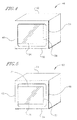
- the display 46 has a first shape memory element 56 disposed along the second edge 50 and a second shape memory element 58 along the fourth edge 54. It may be appreciated that no other shape memory elements are present in Figure 4 besides the elements 56 and 58.
- a display 60 substantially similar in function and configuration to the display 34 referenced in Figure 3 is shown.
- the display 60 has a first edge 62, a second edge 64, a third edge 66, and a fourth edge 68, all substantially similar in configuration to the edges 22, 24, 26, and 28 described in Figures 1 and 2 .
- the display 60 has a first shape memory element 70 disposed along the second edge 70 and a second shape memory element 72 disposed along the fourth edge 68. Further, the display 60 has a third shape memory element 74 disposed along the third edge 66. It may be appreciated that no other shape memory elements are present in Figure 4 besides the elements 70, 72, and 74.
Abstract
Description
- The present invention relates generally to memory shape elements for flexible organic light emitting diode (OLED) display screens.
- Flexible organic light emitting diode (OLED) display screens currently on the market have gained popularity because of their unique ability to bend, fold and flex without breaking, yet still maintain their ability to property display an image after being bent, folded or flexed. Moreover, these display screens can be folded or rolled up for storage even though it is preferable that the screen be flat when in use.
- However, such a screen may eventual develop material bias and it may be inconvenient for a user to hold the screen straight or flat when trying to view something. Including rigid edges with the flexible OLED display screen to keep the screen flat would not allow for the desired flexibility intended by flexible OLEDs.
- Another problem arises when the flexible OLED display screen needs to be stored in a collapsed rather than flat manner by a user for easy storage. There is currently no solution for keeping flexible OLED display screens in a collapsed, compact form even though they may be collapsed into such a form.
- Aspects of the invention are defined in the appended claims.
- Accordingly, in an embodiment, a computing device includes a housing holding a processor accessing a tangible computer readable storage medium, and an input device communicates with the processor. A flexible organic light emitting diode (OLED) display is coupled to the housing for displaying output in response to signals from the processor. The display is movable between a collapsed configuration and an extended configuration in which the display is substantially flat and parallelepiped-shaped. At least one shape memory element is coupled to the display and is energizable under control of the processor to establish a configuration of the display.
- In example embodiments the input device may be a keyboard or keypad arranged on the housing. The shape memory element may straighten when energized in which case the configuration it establishes when energized is the extended configuration, with the shape memory element bending when deenergized.
- When in the collapsed configuration, the display may be rolled up on itself. To this end the display may be materially biased to the collapsed configuration.
- Alternatively, the shape memory element may be straight when deenergized and when energized bends, in which case the configuration it establishes when energized is the collapsed configuration. In this embodiment the display is materially biased to the extended configuration.
- In example implementations the display may be coupled to the housing along a first edge of the display, and the display defines second and third edges perpendicular to the first edge in the extended configuration. The second and third edges terminate in a fourth edge that is parallel to the first edge in the extended configuration. The shape memory element may be disposed along the second edge. Or, the shape memory element may be a first shape memory element and the device can include a second shape memory element and no other shape memory elements, with the second shape memory element being disposed along the fourth edge. Yet again, the shape memory element may be a first shape memory element and the device can include a second shape memory element and a third shape memory element, with the second shape memory element being disposed along the fourth edge and the third shape memory element being disposed along the third edge.
- Another embodiment comprises a computing device comprising:
- housing holding a processor accessing a tangible computer readable storage medium;
- input device communicating with the processor;
- flexible organic light emitting diode (OLED) display coupled to the housing and displaying output in response to signals from the processor, the display being movable between a collapsed configuration and an extended configuration in which the display is substantially flat and parallelepiped-shaped; and at least one shape memory element coupled to the display and energizable under control of the processor to establish a configuration of the display.
- In another embodiment, an information handling system includes a processor, a flexible display presenting images demanded by the processor, and shape memory means controlled by the processor for holding the display flat.
- In another embodiment, a method includes, at boot time of a computer, actuating a shape memory element with energy and permitting the shape memory element to flatten a flexible display. The method also includes maintaining the shape memory element in a state of actuation during computer operation. Upon a predetermined energization condition, the shape memory element is controlled to permit the display to assume a collapsed configuration. If desired, the energization condition may be receipt of a power save signal generated by the computer after a predetermined period of inactivity.
- Embodiments of the invention will now be described with reference to the accompanying drawings, throughout which like parts are referred to by like references, and in which:
-
Figure 1 is a schematic view of an extended configuration of a flexible OLED display screen with at least one memory shape element; -
Figure 2 is a schematic view of a collapsed configuration of a flexible OLED display screen with at least one memory shape element; -
Figure 3 is a perspective view of an example embodiment of the flexible OLED display screen having only one memory shape element; -
Figure 4 is a perspective view of an example embodiment of the flexible OLED display screen having only two memory shape elements; and -
Figure 5 is a perspective view of an example embodiment of the flexible OLEO display screen having three or more memory shape elements. - Beginning in reference to
Figure 1 , a flexible organic light emitting diode (OLED) display is shown. Theflexible OLED display 10 is coupled to ahousing 12. Thehousing 12 includes aprocessor 14 accessing a tangiblecomputer storage medium 16. Further, theprocessor 14 may communicate with adata entry device 18 such as a keyboard, key pad arranged on the housing, touch sensitive slate with handwriting recognition module, remote control device, voice recognition module, or other input device. - The
display 10 is capable of displaying output in response to signals from theprocessor 14. Thus, thekey entry device 18 provides a method to allow a user to determine what is being displayed on thedisplay 10 through its communication with theprocessor 14. - The
display 10 is movable between anextended configuration 20 and a collapsed configuration which will be described inFigure 2 . It is to be understood that theextended configuration 20 shown inFigure 1 is substantially flat and parallelepiped-shaped in non-limiting embodiments. - Further still, the
display 10 is coupled to thehousing 12 along afirst edge 22 of thedisplay 10. The display also has asecond edge 24 and athird edge 26 which are perpendicular to the first edge. Thesecond edge 24 andthird edge 26 may terminate in afourth edge 28 that is parallel to thefirst edge 22 in non-limiting embodiments of theextended configuration 22. - Still referencing
Figure 1 , thedisplay 10 has at least oneshape element 30 coupled to thedisplay 10 which may be disposed along at least one edge of thedisplay 10 in non-limiting embodiments, preferably along an edge perpendicular to thefirst edge 22. Theelement 30 is energizable under control of theprocessor 14 to establish a configuration of thedisplay 10. - The
element 30 may be automatically energized by theprocessor 14 as part of the booting process at power on to flatten the display. Theelement 30 may be automatically deenergized by the processor upon receipt of a power-down signal but prior to totally deenergizing the computer to allow the display to fold or roll up or otherwise collapse. Or, theelement 30 may be automatically deenergized in response to a power save signal that might be generated by the computer after a predetermined period of inactivity. - It is to be understood that the
element 30 need not be disposed along any edge of thedisplay 10 per se, and may be coupled to thedisplay 10 in any manner which allows thedisplay 10 to have the capability to alternate between extended and collapsed configurations. This may also include manufacturing thedisplay 10 with a piezo-electric material that straightens when energized so that no memory shape wires are required. - Now in reference to
Figure 2 , one example of a collapsed configuration of theflexible OLED display 10 referenced inFigure 1 is shown. In the non-limiting example embodiment of thedisplay 10 shown inFigure 2 , the collapsedconfiguration 32 may be a rolled configuration. The collapsedconfiguration 32 of thedisplay 10 remains coupled to ahousing 12, thehousing 12 having aprocessor 14,tangible storage medium 16, andkey entry device 18, all which function according to their respective descriptions provided inFigure 1 . - Furthermore, the
display 10 shown in the collapsedconfiguration 32 still has afirst edge 22, asecond edge 24, athird edge 26, afourth edge 28 even through not shown inFigure 2 . Thedisplay 10 also has at least oneshape element 30 coupled to thedisplay 10 and energizable under control of theprocessor 14. - Thus, it may now be appreciated that, in non-limiting embodiments, the
shape element 30 straightens when energized to hold thedisplay 10 in theextended configuration 20 described inFigure 1 . Theshape element 30 then bends when deenergized into thecollapsed configuration 32 shown inFigure 2 . Furthermore, thedisplay 10 shown inFigure 2 can be materially biased to the collapsedconfiguration 32 when deenergized in non-limiting embodiments. - Alternatively, it is to be understood that in non-limiting embodiments, the
shape memory element 30 may be straight when deenergized and bent when energized. In such an alternative non-limiting embodiment where energizing the at least oneelement 30 results in the collapsedconfiguration 32, thedisplay 10 is materially biased to the extended configuration. However, it is to be understood that in still other non-limiting embodiments, thedisplay 10 may be materially biased toward another configuration not described herein (e.g. a folded collapsed configuration instead of a rolled collapsed configuration). - Now referencing
Figure 3 , a flexible OLED display embodying current principles is shown. In non-limiting embodiments, theflexible OLED display 34 may be flat and parallelepiped-shaped, may be coupled to a housing not shown inFigure 3 , and may be capable of displaying output in response to signals from a processor which is also not shown. Furthermore, thedisplay 34 is substantially similar in function and configuration to thedisplay 10 inFigures 1 and2 (i.e. has a first edge attached to a housing, and second, third and fourth edges subject to the limitations described in reference toFigure 1 ), - The
display 34 is also understood to be movable between a collapsed configuration and an extended configuration, substantially similar to the movement capability of thedisplay 10 described inFigures 1 and2 . Thedisplay 34 may be materially biased toward an extended, collapsed, or alternative configuration in non-limiting embodiments. Thedisplay 34 also has afirst edge 36 substantially similar in function and configuration to thefirst edge 22 shown inFigure 2 . Thefirst edge 36 is understood to be coupled to a housing not shown but substantially similar in function and configuration to thehousing 12 shown inFigure 1 . The display also has asecond edge 38,third edge 40, andfourth edge 42, all of which are substantially similar in configuration to thesecond edge 24,third edge 26, andfourth edge 28 described inFigure 1 . - Still referencing
Figure 3 , it may be appreciated that in the current non-limiting embodiment, thedisplay 34 may have only oneshape memory element 44 disposed along thesecond edge 38 with no shape memory elements along thethird edge 40 orfourth edge 42. - Continuing in reference to
Figure 4 , adisplay 46 substantially similar in function and configuration to thedisplay 34 referenced inFigure 3 is shown. In this non-limiting embodiment, thedisplay 46 has afirst edge 48, asecond edge 50, athird edge 52 and afourth edge 54, all substantially similar in configuration to theedges Figures 1 and2 . Thedisplay 46 has a firstshape memory element 56 disposed along thesecond edge 50 and a secondshape memory element 58 along thefourth edge 54. It may be appreciated that no other shape memory elements are present inFigure 4 besides theelements - Now referencing
Figure 5 , adisplay 60 substantially similar in function and configuration to thedisplay 34 referenced inFigure 3 is shown. In this non-limiting embodiment, thedisplay 60 has afirst edge 62, asecond edge 64, athird edge 66, and afourth edge 68, all substantially similar in configuration to theedges Figures 1 and2 . Thedisplay 60 has a firstshape memory element 70 disposed along thesecond edge 70 and a secondshape memory element 72 disposed along thefourth edge 68. Further, thedisplay 60 has a thirdshape memory element 74 disposed along thethird edge 66. It may be appreciated that no other shape memory elements are present inFigure 4 besides theelements - While describing the present invention in reference to a flexible organic light emitting diode display, it is understood that the memory shape element principles described in
Figures 1-5 may be applied to non-OLED displays as well. - In so far as the embodiments of the invention described above are implemented, at least in part, using software-controlled data processing apparatus, it will be appreciated that a computer program providing such software control and a transmission, storage or other medium by which such a computer program is provided are envisaged as aspects of the present invention.
- While the particular MEMORY SHAPE ELEMENT FOR FLEXIBLE OLED DISPLAY SCREEN is herein shown and described in detail, it is to be understood that the subject matter which is encompassed by the present invention is limited only by the claims.
- Various respective aspects and features of the invention are defined in the appended claims. Combinations of features from the dependent claims may be combined with features of the independent claims as appropriate and not merely as explicitly set out in the claims.
Claims (15)
- A computing device, comprising:a processor;a flexible display presenting images demanded by the processor; andshape memory means controlled by the processor for holding the display flat.
- The device of Claim 1, wherein the display is an OLED display and the shape memory means is at least one shape memory element.
- The device of Claim 1, further comprising:a housing holding the processor, the processor accessing a tangible computer readable storage medium; andan input device communicating with the processor;wherein the flexible display comprises a flexible organic light emitting diode (OLED) display coupled to the housing and displaying output in response to signals from the processor, the display being movable between a collapsed configuration and an extended configuration in which the display is substantially flat and parallelepiped-shaped; andwherein the shape memory means comprises at least one shape memory element coupled to the display and energizable under control of the processor to establish a configuration of the display.
- The device of Claim 3, wherein the input device is a keyboard or keypad arranged on the housing.
- The device of Claim 2, wherein the shape memory element straightens when energized and the configuration it establishes when energized is a flat configuration, the shape memory element bending when deenergized.
- The device of Claim 3, wherein the shape memory element straightens when energized and the configuration it establishes when energized is the extended configuration, the shape memory element bending when deenergized.
- The device of Claim 2, wherein the displays rolls up when the shape memory element is deenergized.
- The device of Claim 3, wherein when in the collapsed configuration the display is rolled.
- The device of Claim 1 or Claim 3, wherein the display is materially biased to a collapsed configuration.
- The device of Claim 2 or Claim 3, wherein the shape memory element is straight when deenergized and when energized bends, and the configuration it establishes when energized is a collapsed configuration, the display being materially biased to a flat or extended configuration.
- The device of Claim 2 or Claim 3, wherein the display is coupled to a housing along a first edge of the display, the display defining second and third edges perpendicular to the first edge in the extended configuration, the second and third edges terminating in a fourth edge that is parallel to the first edge in the extended configuration, the shape memory element being disposed along the second edge.
- The device of Claim 10, wherein the shape memory element is a first shape memory element and the device comprises a second shape memory element and no other shape memory elements, the second shape memory element being disposed along the fourth edge.
- The device of Claim 10 wherein the shape memory element is a first shape memory element and the device comprises a second shape memory element and a third shape memory element, the second shape memory element being disposed along the fourth edge and the third shape memory element being disposed along the third edge.
- Method comprising:at boot time of a computer, actuating a shape memory element with energy;permitting the shape memory element to flatten a flexible display;maintaining the shape memory element in a state of actuation during computer operation; andupon a predetermined energization condition, controlling the shape memory element to permit the display to assume a collapsed configuration.
- The method of claim 14, wherein the energization condition is receipt of a power save signal generated by the computer after a predetermined period of inactivity.
Applications Claiming Priority (1)
| Application Number | Priority Date | Filing Date | Title |
|---|---|---|---|
| US12/578,854 US20110084898A1 (en) | 2009-10-14 | 2009-10-14 | Memory shape element for flexible oled display screen |
Publications (1)
| Publication Number | Publication Date |
|---|---|
| EP2330479A1 true EP2330479A1 (en) | 2011-06-08 |
Family
ID=43768918
Family Applications (1)
| Application Number | Title | Priority Date | Filing Date |
|---|---|---|---|
| EP10187139A Withdrawn EP2330479A1 (en) | 2009-10-14 | 2010-10-11 | Memory shape element for flexible OLED display screen |
Country Status (6)
| Country | Link |
|---|---|
| US (1) | US20110084898A1 (en) |
| EP (1) | EP2330479A1 (en) |
| JP (1) | JP2011085934A (en) |
| CN (1) | CN102043444A (en) |
| RU (1) | RU2500015C2 (en) |
| TW (1) | TW201128521A (en) |
Cited By (1)
| Publication number | Priority date | Publication date | Assignee | Title |
|---|---|---|---|---|
| US10434847B2 (en) | 2014-08-07 | 2019-10-08 | Semiconductor Energy Laboratory Co., Ltd. | Display device and driving support system |
Families Citing this family (20)
| Publication number | Priority date | Publication date | Assignee | Title |
|---|---|---|---|---|
| WO2013025491A1 (en) * | 2011-08-12 | 2013-02-21 | Kang James W | Foldable display structures |
| US9711752B2 (en) | 2011-12-19 | 2017-07-18 | Lg Electronics Inc. | Display apparatus |
| KR101507206B1 (en) * | 2012-02-13 | 2015-03-30 | 엘지디스플레이 주식회사 | Flexible Display Device |
| KR101353010B1 (en) * | 2012-05-02 | 2014-01-23 | 한국과학기술원 | Apparatus and method for flexible display |
| KR102079348B1 (en) | 2012-07-30 | 2020-04-07 | 삼성전자주식회사 | Flexible device and methods for controlling operation thereof |
| KR102070244B1 (en) | 2012-08-01 | 2020-01-28 | 삼성전자주식회사 | Flexible display apparatus and controlling method thereof |
| KR101948665B1 (en) * | 2012-08-23 | 2019-02-18 | 삼성전자주식회사 | Flexible apparatus and control method thereof |
| KR20140026843A (en) * | 2012-08-23 | 2014-03-06 | 삼성전자주식회사 | Method for establishing a communication link and display device thereof |
| US9632539B2 (en) | 2012-10-16 | 2017-04-25 | At&T Intellectual Property I, L.P | Automatic shape adjustment of flexible display |
| CN103792997B (en) * | 2012-10-30 | 2017-06-27 | 联想(北京)有限公司 | The method and electronic equipment of a kind of control electronics |
| CN103873670B (en) * | 2012-12-17 | 2017-04-19 | 联想(北京)有限公司 | Method and electronic equipment for controlling flexible screen shape |
| KR102048922B1 (en) * | 2013-02-13 | 2020-01-09 | 삼성디스플레이 주식회사 | A flexible display device |
| DE102013107675A1 (en) * | 2013-07-18 | 2015-01-22 | Osram Opto Semiconductors Gmbh | Component and method for operating a component |
| KR102073379B1 (en) | 2013-11-26 | 2020-02-05 | 삼성디스플레이 주식회사 | Electronic device having a foldable display |
| CN104505005B (en) | 2014-12-31 | 2018-04-10 | 合肥鑫晟光电科技有限公司 | Display device and display methods |
| CN104821975B (en) | 2015-05-25 | 2018-10-30 | 京东方科技集团股份有限公司 | A kind of flexible display apparatus and its pedestal |
| JP6989248B2 (en) * | 2016-08-30 | 2022-01-05 | 株式会社ジャパンディスプレイ | Display device |
| JP6900160B2 (en) | 2016-08-31 | 2021-07-07 | エルジー ディスプレイ カンパニー リミテッド | Flexible display device |
| JP7027031B2 (en) | 2016-08-31 | 2022-03-01 | エルジー ディスプレイ カンパニー リミテッド | Flexible display device |
| CN111627328B (en) * | 2020-05-07 | 2022-10-21 | Oppo广东移动通信有限公司 | Electronic device and flexible display panel assembly thereof |
Citations (5)
| Publication number | Priority date | Publication date | Assignee | Title |
|---|---|---|---|---|
| US20030048256A1 (en) * | 2001-09-07 | 2003-03-13 | Salmon Peter C. | Computing device with roll up components |
| JP2003280546A (en) * | 2002-03-27 | 2003-10-02 | Matsushita Electric Ind Co Ltd | Self deformation type flexible display, and information processing terminal using the same |
| US20050280732A1 (en) * | 2004-06-09 | 2005-12-22 | Fuji Photo Film Co., Ltd. | Digital camera having mechanism shiftable for portability |
| US20080198541A1 (en) * | 2007-02-16 | 2008-08-21 | Industrial Technology Research Institute | Flexible display |
| JP2009049934A (en) * | 2007-08-22 | 2009-03-05 | Tsuneo Kayama | Cellphone |
Family Cites Families (11)
| Publication number | Priority date | Publication date | Assignee | Title |
|---|---|---|---|---|
| JP2645306B2 (en) * | 1988-05-09 | 1997-08-25 | 有限会社池上パテントインキュベーター | Portable image display |
| JPH11109880A (en) * | 1997-10-02 | 1999-04-23 | Japan Aviation Electron Ind Ltd | Display device |
| JP2003337551A (en) * | 2002-05-22 | 2003-11-28 | Matsushita Electric Ind Co Ltd | Display system |
| JP2005182687A (en) * | 2003-12-24 | 2005-07-07 | Canon Inc | Device for executing at least either of display and input |
| JP4505721B2 (en) * | 2004-02-02 | 2010-07-21 | セイコーエプソン株式会社 | ELECTRO-OPTICAL DEVICE AND ELECTRONIC DEVICE HAVING THE SAME |
| JP3962418B2 (en) * | 2004-03-09 | 2007-08-22 | 千三 小林 | Information display device |
| JP4440003B2 (en) * | 2004-06-09 | 2010-03-24 | 富士フイルム株式会社 | Digital camera |
| JP2006113504A (en) * | 2004-10-12 | 2006-04-27 | Kazunari Tanaka | Storage device having flat or curved surface |
| JP4807947B2 (en) * | 2004-12-09 | 2011-11-02 | アルパイン株式会社 | Display device |
| US8260431B2 (en) * | 2006-02-15 | 2012-09-04 | Dt Systems, Inc. | Multi-mode pet training device |
| RU84613U1 (en) * | 2009-03-04 | 2009-07-10 | Юрий Константинович Низиенко | FOLDING DISPLAY |
-
2009
- 2009-10-14 US US12/578,854 patent/US20110084898A1/en not_active Abandoned
-
2010
- 2010-09-27 TW TW099132614A patent/TW201128521A/en unknown
- 2010-10-11 EP EP10187139A patent/EP2330479A1/en not_active Withdrawn
- 2010-10-13 RU RU2010142156/08A patent/RU2500015C2/en not_active IP Right Cessation
- 2010-10-14 JP JP2010231265A patent/JP2011085934A/en active Pending
- 2010-10-14 CN CN201010513858XA patent/CN102043444A/en active Pending
Patent Citations (5)
| Publication number | Priority date | Publication date | Assignee | Title |
|---|---|---|---|---|
| US20030048256A1 (en) * | 2001-09-07 | 2003-03-13 | Salmon Peter C. | Computing device with roll up components |
| JP2003280546A (en) * | 2002-03-27 | 2003-10-02 | Matsushita Electric Ind Co Ltd | Self deformation type flexible display, and information processing terminal using the same |
| US20050280732A1 (en) * | 2004-06-09 | 2005-12-22 | Fuji Photo Film Co., Ltd. | Digital camera having mechanism shiftable for portability |
| US20080198541A1 (en) * | 2007-02-16 | 2008-08-21 | Industrial Technology Research Institute | Flexible display |
| JP2009049934A (en) * | 2007-08-22 | 2009-03-05 | Tsuneo Kayama | Cellphone |
Cited By (3)
| Publication number | Priority date | Publication date | Assignee | Title |
|---|---|---|---|---|
| US10434847B2 (en) | 2014-08-07 | 2019-10-08 | Semiconductor Energy Laboratory Co., Ltd. | Display device and driving support system |
| US11205356B2 (en) | 2014-08-07 | 2021-12-21 | Semiconductor Energy Laboratory Co., Ltd. | Display device and driving support system |
| US11837112B2 (en) | 2014-08-07 | 2023-12-05 | Semiconductor Energy Laboratory Co., Ltd. | Display device and driving support system |
Also Published As
| Publication number | Publication date |
|---|---|
| CN102043444A (en) | 2011-05-04 |
| JP2011085934A (en) | 2011-04-28 |
| TW201128521A (en) | 2011-08-16 |
| RU2500015C2 (en) | 2013-11-27 |
| US20110084898A1 (en) | 2011-04-14 |
| RU2010142156A (en) | 2012-04-20 |
Similar Documents
| Publication | Publication Date | Title |
|---|---|---|
| EP2330479A1 (en) | Memory shape element for flexible OLED display screen | |
| US10817022B2 (en) | Electronic device and control method therefor | |
| EP3713199B1 (en) | Camera control method and mobile terminal | |
| CN107526395B (en) | Mobile terminal | |
| US20210311526A1 (en) | Electronic device with flexible display and method for operating same | |
| US9898131B2 (en) | Display apparatus and control method of display apparatus | |
| US8982072B2 (en) | Mobile device and method of controlling screen thereof | |
| EP3905646A1 (en) | Screen control method, terminal, and storage medium | |
| US20190324620A1 (en) | Method and device for controlling display screens | |
| US11943530B2 (en) | Electronic device and method for adjusting camera magnification | |
| US10181277B2 (en) | Electronic device and method of reducing power consumption thereof | |
| US9817464B2 (en) | Portable device control method using an electric pen and portable device thereof | |
| KR102471672B1 (en) | Display control method, display panel, display device and electronic device for the same | |
| EP3349094B1 (en) | Method for displaying content and electronic device thereof | |
| US10802622B2 (en) | Electronic device and method for controlling same | |
| US20220206346A1 (en) | Shooting method and electronic device | |
| US20210405857A1 (en) | Electronic device including flexible display | |
| US20140347264A1 (en) | Device and method for displaying an electronic document using a double-sided display | |
| EP3958109A1 (en) | Method for reducing deterioration of display of electronic device, and foldable electronic device using method | |
| CN113299194B (en) | Flexible display assembly, flexible display method and flexible display device | |
| CN116075853A (en) | Method for providing capturing function and electronic device thereof | |
| US20190056836A1 (en) | Electronic device and method for controlling touch sensing signals and storage medium | |
| US20220139357A1 (en) | Electronic device capable of expanding display region and method for controlling screen thereof | |
| KR20210137995A (en) | flexible display device | |
| US8380886B2 (en) | Computer system |
Legal Events
| Date | Code | Title | Description |
|---|---|---|---|
| PUAI | Public reference made under article 153(3) epc to a published international application that has entered the european phase |
Free format text: ORIGINAL CODE: 0009012 |
|
| AK | Designated contracting states |
Kind code of ref document: A1 Designated state(s): AL AT BE BG CH CY CZ DE DK EE ES FI FR GB GR HR HU IE IS IT LI LT LU LV MC MK MT NL NO PL PT RO RS SE SI SK SM TR |
|
| AX | Request for extension of the european patent |
Extension state: BA ME |
|
| 17P | Request for examination filed |
Effective date: 20111102 |
|
| 17Q | First examination report despatched |
Effective date: 20120516 |
|
| GRAP | Despatch of communication of intention to grant a patent |
Free format text: ORIGINAL CODE: EPIDOSNIGR1 |
|
| INTG | Intention to grant announced |
Effective date: 20141006 |
|
| RIN1 | Information on inventor provided before grant (corrected) |
Inventor name: DOUBLE, MATTHEW Inventor name: EBBELING, DANIEL Inventor name: MCCRAY, DENNIS JACOB |
|
| STAA | Information on the status of an ep patent application or granted ep patent |
Free format text: STATUS: THE APPLICATION IS DEEMED TO BE WITHDRAWN |
|
| 18D | Application deemed to be withdrawn |
Effective date: 20150217 |