EP2330235A1 - Garnet-type single crystal, optics using same and related apparatus thereof - Google Patents
Garnet-type single crystal, optics using same and related apparatus thereof Download PDFInfo
- Publication number
- EP2330235A1 EP2330235A1 EP09800464A EP09800464A EP2330235A1 EP 2330235 A1 EP2330235 A1 EP 2330235A1 EP 09800464 A EP09800464 A EP 09800464A EP 09800464 A EP09800464 A EP 09800464A EP 2330235 A1 EP2330235 A1 EP 2330235A1
- Authority
- EP
- European Patent Office
- Prior art keywords
- single crystal
- garnet
- type single
- fluorine
- site
- Prior art date
- Legal status (The legal status is an assumption and is not a legal conclusion. Google has not performed a legal analysis and makes no representation as to the accuracy of the status listed.)
- Granted
Links
Images


Classifications
-
- C—CHEMISTRY; METALLURGY
- C30—CRYSTAL GROWTH
- C30B—SINGLE-CRYSTAL GROWTH; UNIDIRECTIONAL SOLIDIFICATION OF EUTECTIC MATERIAL OR UNIDIRECTIONAL DEMIXING OF EUTECTOID MATERIAL; REFINING BY ZONE-MELTING OF MATERIAL; PRODUCTION OF A HOMOGENEOUS POLYCRYSTALLINE MATERIAL WITH DEFINED STRUCTURE; SINGLE CRYSTALS OR HOMOGENEOUS POLYCRYSTALLINE MATERIAL WITH DEFINED STRUCTURE; AFTER-TREATMENT OF SINGLE CRYSTALS OR A HOMOGENEOUS POLYCRYSTALLINE MATERIAL WITH DEFINED STRUCTURE; APPARATUS THEREFOR
- C30B29/00—Single crystals or homogeneous polycrystalline material with defined structure characterised by the material or by their shape
- C30B29/10—Inorganic compounds or compositions
- C30B29/16—Oxides
- C30B29/22—Complex oxides
- C30B29/28—Complex oxides with formula A3Me5O12 wherein A is a rare earth metal and Me is Fe, Ga, Sc, Cr, Co or Al, e.g. garnets
-
- C—CHEMISTRY; METALLURGY
- C30—CRYSTAL GROWTH
- C30B—SINGLE-CRYSTAL GROWTH; UNIDIRECTIONAL SOLIDIFICATION OF EUTECTIC MATERIAL OR UNIDIRECTIONAL DEMIXING OF EUTECTOID MATERIAL; REFINING BY ZONE-MELTING OF MATERIAL; PRODUCTION OF A HOMOGENEOUS POLYCRYSTALLINE MATERIAL WITH DEFINED STRUCTURE; SINGLE CRYSTALS OR HOMOGENEOUS POLYCRYSTALLINE MATERIAL WITH DEFINED STRUCTURE; AFTER-TREATMENT OF SINGLE CRYSTALS OR A HOMOGENEOUS POLYCRYSTALLINE MATERIAL WITH DEFINED STRUCTURE; APPARATUS THEREFOR
- C30B15/00—Single-crystal growth by pulling from a melt, e.g. Czochralski method
-
- G—PHYSICS
- G02—OPTICS
- G02B—OPTICAL ELEMENTS, SYSTEMS OR APPARATUS
- G02B1/00—Optical elements characterised by the material of which they are made; Optical coatings for optical elements
- G02B1/02—Optical elements characterised by the material of which they are made; Optical coatings for optical elements made of crystals, e.g. rock-salt, semi-conductors
Definitions
- the present invention relates to a garnet-type single crystal represented by a general formula, A 3 B 2 C 3 O 12 (having a crystal structure with three sites A, B and C occupied by cations, wherein A represents an element occupying the site A, B represents an element occupying the site B, C represents an element occupying the site C, O represents an oxygen atom), and to optical components using it and its related instruments.
- micropatteming technology known is an immersion exposure technique (for example, Patent Reference 1).
- the immersion exposure apparatus described in Patent Reference 1 comprises at least a lighting optical system including a photoexposure source of ArF excimer laser, a reticle (mask), a projection optical system, a liquid feeding unit and a liquid recovering unit.
- a lighting optical system including a photoexposure source of ArF excimer laser, a reticle (mask), a projection optical system, a liquid feeding unit and a liquid recovering unit.
- the space between the wafer surface and the optical element on the wafer side of the projection optical system is filled with a liquid while the reticle pattern image is transferred onto the wafer.
- the optical element comprises a liquid, of which the refractive index to the light at a wavelength of 193 nm from the ArF excimer laser is within a range of from 1.60 to 1.66, a substrate (lens) of which the refractive index to the light at a wavelength of 193 nm is within a range of from 2.10 to 2.30, and an antireflection film formed on the surface of the substrate to be in contact with the liquid.
- the liquid used is decalin (C 10 H 18 ); as the substrate, used are garnet (lutetium aluminium garnet [Lu 3 Al 5 O 12 : LuAG], germanate, etc.] and spinel ceramic (Mg 2 Al 2 O 4 , etc.); and as the antireflection film, used is a laminate film of a metal oxide layer and a fluoride layer. Having the constitution, the light from the ArF excimer laser is prevented from reflecting between the liquid and the substrate, therefore attaining a high-resolution immersion exposure apparatus.
- the resolution of the immersion exposure apparatus depends on the material having the smallest refractive index among the refractive index of the resist to be arranged on the wafer, the substrate (lens) of the optical element, and the liquid.
- a resist having a refractive index of more than 1.7 and a liquid having a refractive index of more than 1.6 have been developed; and a substrate having a refractive index of more than 1.7 is needed.
- Patent Reference 1 describes use of LuAG or the like as the substrate having a refractive index of from 2.1 to 2.30, in which, however, the transmittance of the substrate for the light from the photoexposure source (at a wavelength of 193 nm in Patent Reference 1) is not enough and therefore use of an antireflection film for preventing reflectivity depression is needed.
- employed is a known physical or chemical vapor deposition method, which, however, makes the process complicated and increases the production cost. Accordingly, a substrate not requiring an antireflection film is desired.
- the present invention has an object of providing a garnet-type single crystal having an increased transmittance in a vacuum UV range, optical components using it, and its related instruments.
- the invention has the following characteristics.
- the first aspect of the invention is a garnet-type single crystal represented by a general formula, A 3 B 2 C 3 O 12 (having a crystal structure with three sites A, B and C occupied by cations, wherein A represents an element occupying the site A, B represents an element occupying the site B, C represents an element occupying the site C, O represents an oxygen atom), which contains fluorine as an element for attaining any one or both of substituting for the oxygen atom or compensating for oxygen defect.
- the second aspect of the invention is subsidiary to the aspect of the first invention, wherein the fluorine content is at most 5 mol%.
- the third aspect of the invention is subsidiary to the first or second aspect of the invention, which contains, as an element of attaining any one or both of substituting for the element occupying the site A, the element occupying the site B or the element occupying the site C, or compensating for the element defect, at least one element selected from a group consisting of monovalent elements, divalent elements and trivalent elements and having an electronegativity of at most 1.35.
- the fourth aspect of the invention is subsidiary to the third aspect of the invention, wherein the monovalent element is Li.
- the fifth aspect of the invention is subsidiary to the third aspect of the invention, wherein the divalent element is any one or both of Mg or Ca.
- the sixth aspect of the invention is subsidiary to the first aspect of the invention, wherein the garnet-type single crystal is a single crystal selected from a group consisting of Y 3 Al 5 O 12 , Lu 3 Al 5 O 12 and (Y 1 -xLu x ) 3 Al 5 O 12 (0 ⁇ x ⁇ 1).
- the seventh aspect of invention is an optical component that transmits light in a vacuum UV range, which is formed of the garnet-type single crystal of the above first or second aspect of the invention.
- the eighth invention is a semiconductor-related instrument having an optical component that transmits light in a vacuum UV range, wherein the optical component is the optical component of the above seventh aspect of the invention.
- the ninth invention is an optics-related instrument having an optical component that transmits light in a vacuum UV range, wherein the optical component is the optical component of the above seventh aspect of the invention.
- the garnet-type single crystal of the invention contains fluorine, in which the fluorine substitutes for the oxygen atom in the garnet-type single crystal or compensates for oxygen defect.
- fluorine substitutes for the oxygen atom in the garnet-type single crystal or compensates for oxygen defect.
- fluorine increases the band gap in the single crystal owing to the maximum electronegativity thereof.
- the absorption end of the single crystal is shifted to the short wavelength side and the transmittance in a vacuum UV range is thereby increased.
- Compensating for the oxygen defect in the single, crystal, fluorine acts to increase the transmittance at around the absorption end (vacuum UV range) caused by the defects in the single crystal.
- a garnet-type single crystal is known to have a high refractive index, and is therefore applicable not only to lenses in immersion exposure apparatus but also to other optical components such as prisms, window parts, etc.
- These optical components are usable in semiconductor-related instruments such as immersion exposure apparatus, interferometers and the like, and also in optics-related instruments such as imaging apparatus including digital cameras, and microscopes, etc.
- the garnet-type single crystal of the invention and optical components using it and its related instruments are described hereinunder with reference to the drawings.
- the present inventors have found that the transmittance of already-existing garnet-type single crystals can be increased by utilizing the absorption end shift in the transmission spectrum thereof and the defect density control in the crystals, and have completed the present invention.
- the garnet-type single crystal as referred to in this description is a single crystal of a compound having a crystal structure represented by the general formula A 3 B 2 C 3 O 12 .
- A is an element occupying a site A (hereinafter element A)
- B is an element occupying a site B (hereinafter element B)
- C is an element occupying a site C (hereinafter element C)
- O is an oxygen atom.
- the garnet-type single crystal includes three sites, site A, site B and site C occupied by cations, in which each site allows solid solution of plural types of ions. Accordingly, there exist garnet-type single crystals having different compositions.
- the material planning for such garnet-type single crystals may be attained with reference to the relational formula between the composition and the structure described in, for example, LANDOLT-BORNSTEIN Group III, 12a (Garnets and Perovskites), p.p. 22 (1.1.3: Lattice parameters of gamets), Springer-Verlag Berlin; Heidelberg, New York, 1978 .
- the element A may be at least one selected from a group consisting of La, Gd, Y and Lu
- the element B may be at least one selected from a group consisting of Lu, Sc, Ga anal
- the element C may be any one or both of Ga or Al.
- the site A and the site B may be the same element, and the site B and the site C may be the same element. Selected from these element groups, a single crystal having a high refractivity can be constructed.
- YAG Y 3 Al 5 O 12
- LuAG Lu 3 Al 5 O 12
- YLuAG Y 1 - x Lu x
- the present inventors have specifically noted the absorption end of the transmission spectrum of garnet-type single crystals and the defects in the crystals, for the purpose of increasing the transmittance, especially the transmittance in a vacuum UV range (the vacuum UV range is within a range of from 10 nm to 200 nm, especially within a range of from 190 nm to 200 nm) of garnet-type single crystals.
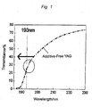
- Fig. 1 is a view showing the transmission spectrum of YAG.
- YAG is a typical example of garnet-type single crystals; and Fig. 1 shows an illustrative transmission spectrum of YAG produced according to a known single crystal growing method. From the transmission spectrum shown in Fig. 1 , it is known that the absorption end of YAG is near the wavelength 193 nm of the light source of an immersion exposure apparatus. The transmittance of YAG at the wavelength 193 nm is about 25% and is low, and is understood to be impracticable. As surrounded by the oval in Fig. 1 , the transmission spectrum shows a shoulder, which suggests that the crystal structure of the single crystal has a high defect density. The inventors have noted the absorption end and the defect in the transmission spectrum of the crystal, and have increased the transmittance thereof.
- the band gap of the garnet-type single crystal may be good to increase; and for increasing the band gap thereof, the electronegativity difference between the cation and the anion in the garnet-type crystal may be good to increase.
- Table 1 shows the Pauling electronegativity.
- the data in Table 1 are extracted from J. E. Huheey et al's "Inorganic Chemistry - principles of structure and reactivity", 4th ed. (Hapere Collins, New York, 1993 ).
- Table 1 I II III II II II II II II II III IV III II I 0 H .
- the garnet-type single crystal of the invention contains fluorine (F).
- fluorine has the largest electronegativity.
- the ionic radius of fluorine is smaller than the ionic radius of O, and therefore fluorine can readily substitutes with O in a garnet-type single crystal to thereby increase the electronegativity difference between the cation and the anion in the garnet-type single crystal.
- the transmittance of the fluorine-containing garnet-type single crystal increases.
- the fluorine content is preferably at most 5 mol%. Even a little substitution of O with F could increase the band gap, and therefore the absorption end could shift toward he short wavelength side and the transmittance in a vacuum UV range increases. When the fluorine content is more than 5 mol%, it is unfavorable since the crystal structure could not be maintained.
- the garnet-type single crystal of the invention contains, in addition to fluorine, at least one element selected from a group consisting of monovalent elements, divalent elements and trivalent elements and having an electronegativity of at most 1.35.
- At least one element selected from the group consisting of monovalent elements, divalent elements and trivalent elements substitutes for the cation element (element A, element B and element C) in the garnet-type single crystal.
- the electronegativity of the selected element is at most 1.35, with which, therefore, electronegativity difference between the cation and the anion of the garnet-type single crystal can increase.
- the electronegativity is more than 1.35, it is unfavorable since the electroconductivity difference decreases.
- an example of the monovalent element is Li and that of the divalent element is Ca.
- the content of the selected element is preferably from 0 mol% to 5 mol%. At least fluorine may be good to be contained in the garnet-type single crystal, and therefore, the garnet-type single crystal does not always contain the selected element. When the content is more than 5 mol%, it is unfavorable since the crystal structure could not be maintained.
- the shoulder in the transmission spectrum is caused by the incompleteness of the crystal structure in the single crystal, or that is, by the defect (oxygen defect and cation defect) therein. Reducing the defect concentration could cancel the shoulder in the transmission spectrum, thereby increasing the transmittance.
- the garnet-type single crystal of the invention contains fluorine (F) as described above, and fluorine has a smaller ionic radius than O and can therefore readily fill up the oxygen defect. As a result, the shoulder in the transmission spectrum is lost and the transmittance is thereby increased.
- the fluorine content is, as described above, preferably at most 5 mol%.
- the garnet-type single crystal of the invention contains, in addition to fluorine, at least one element selected from the group consisting of monovalent elements, divalent elements and trivalent elements. At least one such element selected from the group consisting of monovalent elements, divalent elements and trivalent elements can readily fill up the cation defect in the cation site (site A, site B and site C) in the garnet-type single crystal.
- an example of the monovalent element is Li and that of the divalent element is Mg.
- the selected element may be basically any substitutable element; however, in consideration of the absorption end shift to the short wavelength side shown in the above (1), preferred are the elements having an electronegativity of at most 1.35 shown in Table 1. Accordingly, the monovalent element to be selected is preferably Li, and the divalent element is preferably any one or both of Mg or Ca.
- the garnet-type single crystal of the invention is such that the absorption end in the transmission spectrum thereof is shifted toward the short wavelength side and the oxygen defect therein is controlled, and therefore the transmittance of the crystal in a vacuum UV range is increased.
- the garnet-type single crystal is favorable for the lens (optical component) of an immersion exposure apparatus, and for a lens material taking advantage of high transmittance, etc.
- the garnet-type single crystal of the invention is known to have a high refractive index; and above all, it has been clarified that a fluorine-added YAG single crystal in which the element A is Y, the element B and the element C are Al has a refractive index of 2.144 in a vacuum UV range (this means the range having a wavelength of from 10 nm to 200 nm), for example, at a wavelength of 193 nm.
- the present inventors have found that, of garnet-type single crystals, the refractive index of the fluorine-added YAG single crystal greatly differs from the refractive index value of the crystals heretofore known in the art, and is a large value exceeding over the common knowledge.
- the refractive index of 2.144 in a vacuum UV range (for example, at a wavelength of 193 nm) satisfies the requirement for the projection lens in an immersion exposure apparatus (in that the refractive index is at least 1.7), and therefore, of the garnet-type single crystals of the invention, the fluorine-added YAG single crystal is especially favorable for the projection lens for a immersion exposure apparatus.
- the fluorine-added YAG single crystal has a refractive index on the same level as the refractive index of already-existing LuAG, and in particular, the refractive index thereof at a wavelength of 193 nm is higher than the refractive index of LuAG and the transmittance thereof is also higher than that of LuAG. Accordingly, when the fluorine-added YAG single crystal is used in place of LuAG therein, the resolution of the immersion exposure apparatus can be further increased not requiring an antireflection film.
- YAG of the above-mentioned YAG, LuAG and YLuAG from the viewpoint of the transmittance and the refractive index thereof.
- the garnet-type single crystal of the invention can be produced, for example, according to a known crystal growing method such as a Czochralski (CZ) method or the like, except that the starting melt contains a fluorine source or a fluorine source and a selected element source.
- the fluorine source may be selected from a group consisting of a compound of the element A and fluorine constituting the garnet-type single crystal, a compound of the element B and fluorine, a compound of the element C and fluorine, their mixture, and a fluorine-containing gas.
- the element A is Y
- YF 3 is employed as the fluorine source.
- the fluorine-containing gas is a gas prepared by substituting a part or all of Ar or N 2 therein with a fluorine-containing gas such as CF 4 , CH 2 F 2 , CH 3 F, C 2 H 5 F, HF, F 2 , etc.
- the element source may be selected from a group consisting of a material of the simple substance of the element to be selected, an oxide of the element to be selected, a compound of the element A constituting the garnet-type single crystal and the element to be selected, a compound of the element B and the element to be selected, a compound of the element C and the element to e selected, their mixtures and their fluorides.
- the garnet-type single substance alone is described in detail hereinabove; however, the above principle ((1) absorption end shift and (2) defect concentration control) is applicable to ordinary oxide materials (for example, cubic spinel-type crystals such as typically (Mg,Zn)Al 2 O 4 , CaAl 2 O 4 , CaB 2 O 4 , and LiAl 5 O 8 , cubic perovskite-type crystals, MgO, (Mg,Zn)O, LiNbO 3 , LiTaO 3 , Mg-doped LiNbO 3 , Mg-doped LiTaO 3 , Al 2 O 3 , TiO 2 , etc.). It is obvious that any one or both of substitution of oxygen with fluorine or filling up of oxygen defect with fluorine in the oxide increases the transmittance of the above-mentioned ordinary oxide materials.
- ordinary oxide materials for example, cubic spinel-type crystals such as typically (Mg,Zn)Al 2 O 4 , CaAl 2 O
- a fluorine-containing garnet-type single crystal was produced. Used was a garnet-type single crystal of a general formula A 3 B 2 C 3 O 12 where the element A is Y, the element B and the element C are Al, Y 2 Al 5 O 12 (YAG). Hereinunder the garnet-type single crystal is referred to as a fluorine-containing YAG single crystal.
- the fluorine-containing YAG single crystal was grown according to a Czochralski method.
- a Y 2 O 3 powder, an Al 2 O 3 powder and a YF 3 powder each having a purity of 4N were weighed and mixed in a molar ratio of 2.9/5/0.2, and then shaped by pressing.
- the press-shaped starting material mixture powder was filled in an Ir crucible, and set in a ceramic-made heat-insulating material.
- the Ir crucible was heated up to about 2000°C near the melting point of the starting material mixture powder, through high-frequency induction heating thereby to melt the starting material mixture powder. In this, F in the melt was 0.2 mol%.
- a YAG seed crystal previously shaped and fixed to a seed holder was kept in contact with the melt so as to be habituated to it and the temperature was thereby controlled. Subsequently, this was pulled up at a pulling rate of 1 mm/hr and with rotating at a rotation frequency of 10 rpm, thereby growing a fluorine-containing YAG single crystal.
- the fluorine-containing YAG single crystal was observed.
- the observation result is shown in Fig. 2 .
- the wavelength dependence of the refractive index of the fluorine-containing YAG single crystal was measured.
- the fluorine-containing YAG single crystal was cut and polished to prepare a prism.
- employed was a minimum deviation method.
- the found data are shown in Fig. 3 .
- the obtained fluorine-containing YAG single crystal was cut and polished, and its transmission spectrum was measured.
- the thickness of the sample for measurement was 1 mm.
- the found data are shown in Fig. 4 .
- the evaluation of the fluorine-containing YAG single crystal is described below.
- An additive-free garnet-type single crystal (hereinafter this is referred to as an additive-free YAG single crystal) was produced according to the same process as in Example 1 except that the YF 3 powder was not used. Thus obtained, the additive-free YAG single crystal was cut and polished in the same manner as in Example 1, and its transmission spectrum was measured. The found data are additionally shown in Fig. 3 .
- Fig. 2 is a photographic picture of the fluorine-containing YAG single crystal produced in Example 1.
- Fig. 3 is a view showing the wavelength dependence of the refractive index of the fluorine-containing YAG single crystal produced in Example 1.
- the refractive index in a vacuum UV range was at least 2.1; and more precisely, the refractive index at a wavelength of 193 nm was 2.144. This value is far larger than the value of the refractive index (2.0) heretofore known in the art, and is larger than that of LuAG. This suggests that the fluorine-containing YAG single crystal would be favorable for the projection lens in an immersion exposure system in place of LuAG. As having such a high refractive index, the single crystal is expected to realize high resolution immersion exposure apparatus.
- the applicability of the fluorine-containing YAG single crystal to non-spherical lenses of imaging apparatus such as digital cameras or the like may be taken into consideration; and since the single crystal has a high refractive index, the lens thickness may be reduced and the imaging apparatus is expected to be down-sized. Further, the applicability of the fluorine-containing YAG single crystal to prisms, window parts and the like as optical components other than lens may be taken into consideration. Employing such optical components for interferometers as semiconductor-related instruments and also for microscopes and others as optics-related instruments is also taken into consideration. In addition, since the starting materials for the fluorine-containing YAG single crystal are inexpensive and easily available, the single crystal enables cost reduction as compared with LuAG.
- Fig. 4 is a view showing the transmission spectrum of the YAG single crystal measured in Example 1 and Comparative Example 1.
- the transmission spectrum of Comparative Example 1 is the same as the transmission spectrum of YAG shown in Fig. 1 .
- the absorption end of the transmission spectrum is shifted to the short wavelength side owing to the addition of fluorine.
- the transmittance (50%) in a vacuum UV range (especially at a wavelength of 193 nm) of the fluorine-containing YAG single crystal (F-added YAG) in Example 1 is higher by 2 times than the transmittance (25%) of the additive-free YAG in Comparative Example 1. Accordingly, when the F-added YAG is used as the substrate for the optical element of the high-resolution immersion exposure apparatus, the apparatus does not require an antireflection film and therefore can attain cost reduction.
- Fig. 5 is a schematic view of an immersion exposure apparatus using the lens formed of the fluorine-containing YAG single crystal produced in Example 1.
- the immersion exposure apparatus 100 comprises a lighting optical system 111, a reticle (mask) 112, a projection optical system 113, a projection lens 114, a liquid feeding unit 115, a liquid recovering unit 116, a liquid 117, and a stage 118 with a photoexposure substrate 119 mounted thereon.
- the photoexposure substrate 119 is coated with a resist 120.
- a resist 120 employable is a known immersion resist, and for example, usable is a commercially-available methacrylic resin-base ArF resist.
- the lighting optical system 111 includes a light source, and functions so that the reticle 112 is irradiated with the light from the light source.
- an ArF excimer laser having a wavelength of 193 nm was used as the light source.
- the lighting optical system 110 may comprise various optical elements such as mirror, lens and others as combined.
- the reticle 112 is an original plate to be transcribed onto the photoexposure substrate 119 through exposure to light.
- the projection optical system 113 At the top of the projection optical system 113, there is provided a projection lens 114, and the projection optical system 113 and the projection lens 114 function so as to reduce the light having passed through the reticle 112 and to make the photoexposure substrate 119 irradiated with the thus-reduced light.
- the projection optical system 113 may comprise various optical elements such as mirror, lens and others as combined.
- the projection lens 114 is formed of the fluorine-containing YAG single crystal produced in Example 1.
- the immersion exposure apparatus 100 is provided with a liquid feeding unit 115 and the liquid recovering unit 116 so that the space between the projection lens 114 and the resist 120 could be filled with a liquid 117.
- a liquid 117 employed is a known high-refractivity liquid.
- the immersion exposure apparatus 100 acts as follow.
- the reticle 112 is irradiated with the light from the light source in the lighting optical system 111.
- the light having passed through the reticle 112 then passes through the projection optical system 113 and the projection lens 114 in that order
- the pattern of the reticle 112 is reduced.
- the liquid feeding unit 115 and the liquid recovering unit 116 function so that the space between the projection lens 114 and the resist 120 could be filled up with the liquid 117.
- the light of the reduced pattern is refracted by the liquid 117, and the resist 120 is thus exposed to the light.
- the absorption end of the transmission spectrum is shifted toward the short wavelength side, and the oxygen defect is controlled in the single crystal; and therefore, the transmittance of the single crystal in a vacuum UV range is increased.
- the garnet-type single crystal has a high refractive index, it is applicable not only to lenses of immersion exposure apparatus but also to other optical components such as prisms, window parts, etc. These optical components are usable in semiconductor-related instruments such as immersion exposure apparatus, interferometers and the like, and also in optics-related instruments such as imaging apparatus including digital cameras, and microscopes, etc.
Landscapes
- Chemical & Material Sciences (AREA)
- Crystallography & Structural Chemistry (AREA)
- Engineering & Computer Science (AREA)
- Materials Engineering (AREA)
- Metallurgy (AREA)
- Organic Chemistry (AREA)
- Physics & Mathematics (AREA)
- Inorganic Chemistry (AREA)
- General Physics & Mathematics (AREA)
- Optics & Photonics (AREA)
- Crystals, And After-Treatments Of Crystals (AREA)
- Optical Modulation, Optical Deflection, Nonlinear Optics, Optical Demodulation, Optical Logic Elements (AREA)
Abstract
Description
- The present invention relates to a garnet-type single crystal represented by a general formula, A3B2C3O12 (having a crystal structure with three sites A, B and C occupied by cations, wherein A represents an element occupying the site A, B represents an element occupying the site B, C represents an element occupying the site C, O represents an oxygen atom), and to optical components using it and its related instruments.
- These days required are increased integration of electronic devices and increased operation speed thereof, and for satisfying these requirements, the development of micropatteming technology is remarkable. As micropatteming technology, known is an immersion exposure technique (for example, Patent Reference 1).
- The immersion exposure apparatus described in
Patent Reference 1 comprises at least a lighting optical system including a photoexposure source of ArF excimer laser, a reticle (mask), a projection optical system, a liquid feeding unit and a liquid recovering unit. In the immersion exposure apparatus, the space between the wafer surface and the optical element on the wafer side of the projection optical system is filled with a liquid while the reticle pattern image is transferred onto the wafer. - The optical element comprises a liquid, of which the refractive index to the light at a wavelength of 193 nm from the ArF excimer laser is within a range of from 1.60 to 1.66, a substrate (lens) of which the refractive index to the light at a wavelength of 193 nm is within a range of from 2.10 to 2.30, and an antireflection film formed on the surface of the substrate to be in contact with the liquid. As the liquid, used is decalin (C10H18); as the substrate, used are garnet (lutetium aluminium garnet [Lu3Al5O12: LuAG], germanate, etc.] and spinel ceramic (Mg2Al2O4, etc.); and as the antireflection film, used is a laminate film of a metal oxide layer and a fluoride layer. Having the constitution, the light from the ArF excimer laser is prevented from reflecting between the liquid and the substrate, therefore attaining a high-resolution immersion exposure apparatus.
- On the other hand, it is known that the resolution of the immersion exposure apparatus depends on the material having the smallest refractive index among the refractive index of the resist to be arranged on the wafer, the substrate (lens) of the optical element, and the liquid. A resist having a refractive index of more than 1.7 and a liquid having a refractive index of more than 1.6 have been developed; and a substrate having a refractive index of more than 1.7 is needed.
-
Patent Reference 1 describes use of LuAG or the like as the substrate having a refractive index of from 2.1 to 2.30, in which, however, the transmittance of the substrate for the light from the photoexposure source (at a wavelength of 193 nm in Patent Reference 1) is not enough and therefore use of an antireflection film for preventing reflectivity depression is needed. For providing such an antireflection film, employed is a known physical or chemical vapor deposition method, which, however, makes the process complicated and increases the production cost. Accordingly, a substrate not requiring an antireflection film is desired. - Patent Reference 1:
JP-A 2008-113004 - In consideration of the above-mentioned situation, the present invention has an object of providing a garnet-type single crystal having an increased transmittance in a vacuum UV range, optical components using it, and its related instruments.
- For solving the above-mentioned problems, the invention has the following characteristics.
- The first aspect of the invention is a garnet-type single crystal represented by a general formula, A3B2C3O12 (having a crystal structure with three sites A, B and C occupied by cations, wherein A represents an element occupying the site A, B represents an element occupying the site B, C represents an element occupying the site C, O represents an oxygen atom), which contains fluorine as an element for attaining any one or both of substituting for the oxygen atom or compensating for oxygen defect.
- The second aspect of the invention is subsidiary to the aspect of the first invention, wherein the fluorine content is at most 5 mol%.
- The third aspect of the invention is subsidiary to the first or second aspect of the invention, which contains, as an element of attaining any one or both of substituting for the element occupying the site A, the element occupying the site B or the element occupying the site C, or compensating for the element defect, at least one element selected from a group consisting of monovalent elements, divalent elements and trivalent elements and having an electronegativity of at most 1.35.
- The fourth aspect of the invention is subsidiary to the third aspect of the invention, wherein the monovalent element is Li.
- The fifth aspect of the invention is subsidiary to the third aspect of the invention, wherein the divalent element is any one or both of Mg or Ca.
- The sixth aspect of the invention is subsidiary to the first aspect of the invention, wherein the garnet-type single crystal is a single crystal selected from a group consisting of Y3Al5O12, Lu3Al5O12 and (Y1-xLux)3Al5O12 (0 < x < 1).
- The seventh aspect of invention is an optical component that transmits light in a vacuum UV range, which is formed of the garnet-type single crystal of the above first or second aspect of the invention.
- The eighth invention is a semiconductor-related instrument having an optical component that transmits light in a vacuum UV range, wherein the optical component is the optical component of the above seventh aspect of the invention.
- The ninth invention is an optics-related instrument having an optical component that transmits light in a vacuum UV range, wherein the optical component is the optical component of the above seventh aspect of the invention.
- The garnet-type single crystal of the invention contains fluorine, in which the fluorine substitutes for the oxygen atom in the garnet-type single crystal or compensates for oxygen defect. Substituting for the oxygen atom in the single crystal, fluorine increases the band gap in the single crystal owing to the maximum electronegativity thereof. As a result, the absorption end of the single crystal is shifted to the short wavelength side and the transmittance in a vacuum UV range is thereby increased. Compensating for the oxygen defect in the single, crystal, fluorine acts to increase the transmittance at around the absorption end (vacuum UV range) caused by the defects in the single crystal.
- A garnet-type single crystal is known to have a high refractive index, and is therefore applicable not only to lenses in immersion exposure apparatus but also to other optical components such as prisms, window parts, etc. These optical components are usable in semiconductor-related instruments such as immersion exposure apparatus, interferometers and the like, and also in optics-related instruments such as imaging apparatus including digital cameras, and microscopes, etc.
-
-
Fig. 1 is a view showing the transmission spectrum of YAG. -
Fig. 2 is a photographic picture of the fluorine-containing YAG single crystal produced in Example 1. -
Fig. 3 is a view showing the wavelength dependence of the refractive index of the fluorine-containing YAG single crystal produced in Example 1. -
Fig. 4 is a view showing the transmission spectrum of the YAG single crystal measured in Example 1 and Comparative Example 1. -
Fig. 5 is a schematic view of an immersion exposure apparatus using the lens formed of the fluorine-containing YAG single crystal produced in Example 1. - The garnet-type single crystal of the invention, and optical components using it and its related instruments are described hereinunder with reference to the drawings. The present inventors have found that the transmittance of already-existing garnet-type single crystals can be increased by utilizing the absorption end shift in the transmission spectrum thereof and the defect density control in the crystals, and have completed the present invention.
- The garnet-type single crystal as referred to in this description is a single crystal of a compound having a crystal structure represented by the general formula A3B2C3O12. In this, A is an element occupying a site A (hereinafter element A), B is an element occupying a site B (hereinafter element B), C is an element occupying a site C (hereinafter element C), O is an oxygen atom. Specifically, the garnet-type single crystal includes three sites, site A, site B and site C occupied by cations, in which each site allows solid solution of plural types of ions. Accordingly, there exist garnet-type single crystals having different compositions. The material planning for such garnet-type single crystals may be attained with reference to the relational formula between the composition and the structure described in, for example, LANDOLT-BORNSTEIN Group III, 12a (Garnets and Perovskites), p.p. 22 (1.1.3: Lattice parameters of gamets), Springer-Verlag Berlin; Heidelberg, New York, 1978.
- In particular, for use for the lens (optical component) of an immersion exposure apparatus, a type of a semiconductor-related instrument, the element A may be at least one selected from a group consisting of La, Gd, Y and Lu, the element B may be at least one selected from a group consisting of Lu, Sc, Ga anal, and the element C may be any one or both of Ga or Al. Naturally, the site A and the site B may be the same element, and the site B and the site C may be the same element. Selected from these element groups, a single crystal having a high refractivity can be constructed.
- Above all, from the viewpoint of the producibility and the practicability thereof, preferred are Y3Al5O12 (hereinafter YAG) where the element A is Y and the element B and the element C are Al; Lu3Al5O12 (hereinafter LuAG) where the element A is Lu and the element B and the element C are Al; and (Y1-xLux)Al5O12 (0 < x < 1) (hereinafter YLuAG) where the element A is Y and Lu and the element B and the element C are Al.
- The present inventors have specifically noted the absorption end of the transmission spectrum of garnet-type single crystals and the defects in the crystals, for the purpose of increasing the transmittance, especially the transmittance in a vacuum UV range (the vacuum UV range is within a range of from 10 nm to 200 nm, especially within a range of from 190 nm to 200 nm) of garnet-type single crystals.
-
Fig. 1 is a view showing the transmission spectrum of YAG. - YAG is a typical example of garnet-type single crystals; and
Fig. 1 shows an illustrative transmission spectrum of YAG produced according to a known single crystal growing method. From the transmission spectrum shown inFig. 1 , it is known that the absorption end of YAG is near thewavelength 193 nm of the light source of an immersion exposure apparatus. The transmittance of YAG at thewavelength 193 nm is about 25% and is low, and is understood to be impracticable. As surrounded by the oval inFig. 1 , the transmission spectrum shows a shoulder, which suggests that the crystal structure of the single crystal has a high defect density. The inventors have noted the absorption end and the defect in the transmission spectrum of the crystal, and have increased the transmittance thereof. - In the transmission spectrum shown in
Fig. 1 , when the absorption end is shifted to the short wavelength side shown by the arrow, then the transmittance in a vacuum UV range could be increased. In detail, the absorption end is correlated with the band gap, which is simply represented by a formula E = hc/λ (where E means the band gap; hc means the photon energy; λ means the wavelength at the absorption end). When the wavelength λ at the absorption end is shifted to the short wavelength side, then the band gap increases. Accordingly, for increasing the transmittance of a garnet-type single crystal, the band gap of the garnet-type single crystal may be good to increase; and for increasing the band gap thereof, the electronegativity difference between the cation and the anion in the garnet-type crystal may be good to increase. - Table 1 shows the Pauling electronegativity. The data in Table 1 are extracted from J. E. Huheey et al's "Inorganic Chemistry - principles of structure and reactivity", 4th ed. (Hapere Collins, New York, 1993).
Table 1 I II III II II II II II II II I II III IV III II I 0 H . He 2.2 Li Be B C N 0 F Ne 0.98 1.57 2.04 2.55 3.04 3.44 3.98 - Na Mg Al Si P S Cl Ar 0.93 1.31 1.61 1.90 2.19 2.58 3.16 - K Ca Sc Ti V Cr Mn Fe Co Ni Cu Zn Ga Ge As Se Be Kr 0.82 1.00 1.36 1.54 1.63 1.66 1.55 1.83 1.88 1.91 1.90 1.65 1.81 2.01 2.18 2.55 2.96 3.00 1.96III 2.00II Rb Sr Y Zr Nb Mo Tc Ru Rh Pd Ag Cd In Sn Sb Te I Xe 0.82 0.95 1.22 1.33 2.16 1.9 2.2 2.28 2.20 1.93 1.69 1.78 1.96 2.05 2.1 2.66 2.60 1.6V 2.19III 1.80II 2.24IV 2.27V 2.35VI Cs Ba La Hf Ta W Re Os Ir Pt Au Hg TI Pb Bi Po At Rn 0.79 0.89 1.10 1.3 1.5 2.36 1.9 22 2.20 2.28 2.54 2.00 2.04 2.33 2.02 2.0 2.2 - 1.62I 1.87II Fr Ra Ac Rf Db Sg Bh Hs Mt 0.7 0.9 1.1 Ce Pr Nd Pm Sm Eu Gd Tb Dy H0 Er Tm Yb Lu 1.12 1.13 1.14 - 1.17 - 1.20 - 122 1.23 1.24 1.25 - 1.27 Th Pa U Np Pu Am Cm Bk Cf Es Fm Md No Lr 1.3 1.5 1.38 1.36 1.28 1.3 1.3 1.3 1.3 1.3 1.3 1.3 1.3 - - The garnet-type single crystal of the invention contains fluorine (F). As in Table 1, fluorine has the largest electronegativity. The ionic radius of fluorine is smaller than the ionic radius of O, and therefore fluorine can readily substitutes with O in a garnet-type single crystal to thereby increase the electronegativity difference between the cation and the anion in the garnet-type single crystal. As a result, the transmittance of the fluorine-containing garnet-type single crystal increases.
- The fluorine content is preferably at most 5 mol%. Even a little substitution of O with F could increase the band gap, and therefore the absorption end could shift toward he short wavelength side and the transmittance in a vacuum UV range increases. When the fluorine content is more than 5 mol%, it is unfavorable since the crystal structure could not be maintained.
- Preferably, the garnet-type single crystal of the invention contains, in addition to fluorine, at least one element selected from a group consisting of monovalent elements, divalent elements and trivalent elements and having an electronegativity of at most 1.35. At least one element selected from the group consisting of monovalent elements, divalent elements and trivalent elements substitutes for the cation element (element A, element B and element C) in the garnet-type single crystal. The electronegativity of the selected element is at most 1.35, with which, therefore, electronegativity difference between the cation and the anion of the garnet-type single crystal can increase. When the electronegativity is more than 1.35, it is unfavorable since the electroconductivity difference decreases. More preferably, from the viewpoint of the ionic radius and the electronegativity thereof, an example of the monovalent element is Li and that of the divalent element is Ca.
- The content of the selected element is preferably from 0 mol% to 5 mol%. At least fluorine may be good to be contained in the garnet-type single crystal, and therefore, the garnet-type single crystal does not always contain the selected element. When the content is more than 5 mol%, it is unfavorable since the crystal structure could not be maintained.
- As described in the above with reference to
Fig. 1 , the shoulder in the transmission spectrum is caused by the incompleteness of the crystal structure in the single crystal, or that is, by the defect (oxygen defect and cation defect) therein. Reducing the defect concentration could cancel the shoulder in the transmission spectrum, thereby increasing the transmittance. - The garnet-type single crystal of the invention contains fluorine (F) as described above, and fluorine has a smaller ionic radius than O and can therefore readily fill up the oxygen defect. As a result, the shoulder in the transmission spectrum is lost and the transmittance is thereby increased. The fluorine content is, as described above, preferably at most 5 mol%.
- Preferably, the garnet-type single crystal of the invention contains, in addition to fluorine, at least one element selected from the group consisting of monovalent elements, divalent elements and trivalent elements. At least one such element selected from the group consisting of monovalent elements, divalent elements and trivalent elements can readily fill up the cation defect in the cation site (site A, site B and site C) in the garnet-type single crystal. Above all, from the viewpoint of the ionic radius thereof, preferably, an example of the monovalent element is Li and that of the divalent element is Mg. The selected element may be basically any substitutable element; however, in consideration of the absorption end shift to the short wavelength side shown in the above (1), preferred are the elements having an electronegativity of at most 1.35 shown in Table 1. Accordingly, the monovalent element to be selected is preferably Li, and the divalent element is preferably any one or both of Mg or Ca.
- The garnet-type single crystal of the invention is such that the absorption end in the transmission spectrum thereof is shifted toward the short wavelength side and the oxygen defect therein is controlled, and therefore the transmittance of the crystal in a vacuum UV range is increased. The garnet-type single crystal is favorable for the lens (optical component) of an immersion exposure apparatus, and for a lens material taking advantage of high transmittance, etc.
- The garnet-type single crystal of the invention is known to have a high refractive index; and above all, it has been clarified that a fluorine-added YAG single crystal in which the element A is Y, the element B and the element C are Al has a refractive index of 2.144 in a vacuum UV range (this means the range having a wavelength of from 10 nm to 200 nm), for example, at a wavelength of 193 nm. The present inventors have found that, of garnet-type single crystals, the refractive index of the fluorine-added YAG single crystal greatly differs from the refractive index value of the crystals heretofore known in the art, and is a large value exceeding over the common knowledge.
- To that effect, the refractive index of 2.144 in a vacuum UV range (for example, at a wavelength of 193 nm) satisfies the requirement for the projection lens in an immersion exposure apparatus (in that the refractive index is at least 1.7), and therefore, of the garnet-type single crystals of the invention, the fluorine-added YAG single crystal is especially favorable for the projection lens for a immersion exposure apparatus. Of the garnet-type single crystals of the invention, the fluorine-added YAG single crystal has a refractive index on the same level as the refractive index of already-existing LuAG, and in particular, the refractive index thereof at a wavelength of 193 nm is higher than the refractive index of LuAG and the transmittance thereof is also higher than that of LuAG. Accordingly, when the fluorine-added YAG single crystal is used in place of LuAG therein, the resolution of the immersion exposure apparatus can be further increased not requiring an antireflection film. In case where the garnet-type single crystal of the invention is used as the lens of an immersion exposure apparatus, preferred is YAG of the above-mentioned YAG, LuAG and YLuAG from the viewpoint of the transmittance and the refractive index thereof.
- The garnet-type single crystal of the invention can be produced, for example, according to a known crystal growing method such as a Czochralski (CZ) method or the like, except that the starting melt contains a fluorine source or a fluorine source and a selected element source. The fluorine source may be selected from a group consisting of a compound of the element A and fluorine constituting the garnet-type single crystal, a compound of the element B and fluorine, a compound of the element C and fluorine, their mixture, and a fluorine-containing gas. For example, when the element A is Y, YF3 is employed as the fluorine source. The fluorine-containing gas is a gas prepared by substituting a part or all of Ar or N2 therein with a fluorine-containing gas such as CF4, CH2F2, CH3F, C2H5F, HF, F2, etc.
- The element source may be selected from a group consisting of a material of the simple substance of the element to be selected, an oxide of the element to be selected, a compound of the element A constituting the garnet-type single crystal and the element to be selected, a compound of the element B and the element to be selected, a compound of the element C and the element to e selected, their mixtures and their fluorides.
- The garnet-type single substance alone is described in detail hereinabove; however, the above principle ((1) absorption end shift and (2) defect concentration control) is applicable to ordinary oxide materials (for example, cubic spinel-type crystals such as typically (Mg,Zn)Al2O4, CaAl2O4, CaB2O4, and LiAl5O8, cubic perovskite-type crystals, MgO, (Mg,Zn)O, LiNbO3, LiTaO3, Mg-doped LiNbO3, Mg-doped LiTaO3, Al2O3, TiO2, etc.). It is obvious that any one or both of substitution of oxygen with fluorine or filling up of oxygen defect with fluorine in the oxide increases the transmittance of the above-mentioned ordinary oxide materials.
- The garnet-type single crystal of the invention is further described with reference to Examples shown below. Needless-to-say, the invention should not be limited by the following Examples.
- A fluorine-containing garnet-type single crystal was produced. Used was a garnet-type single crystal of a general formula A3B2C3O12 where the element A is Y, the element B and the element C are Al, Y2Al5O12 (YAG). Hereinunder the garnet-type single crystal is referred to as a fluorine-containing YAG single crystal. The fluorine-containing YAG single crystal was grown according to a Czochralski method.
- A Y2O3 powder, an Al2O3 powder and a YF3 powder each having a purity of 4N were weighed and mixed in a molar ratio of 2.9/5/0.2, and then shaped by pressing. The press-shaped starting material mixture powder was filled in an Ir crucible, and set in a ceramic-made heat-insulating material. The Ir crucible was heated up to about 2000°C near the melting point of the starting material mixture powder, through high-frequency induction heating thereby to melt the starting material mixture powder. In this, F in the melt was 0.2 mol%.
- Next, a YAG seed crystal previously shaped and fixed to a seed holder was kept in contact with the melt so as to be habituated to it and the temperature was thereby controlled. Subsequently, this was pulled up at a pulling rate of 1 mm/hr and with rotating at a rotation frequency of 10 rpm, thereby growing a fluorine-containing YAG single crystal.
- Thus produced, the fluorine-containing YAG single crystal was observed. The observation result is shown in
Fig. 2 . The wavelength dependence of the refractive index of the fluorine-containing YAG single crystal was measured. As a sample for measurement, the fluorine-containing YAG single crystal was cut and polished to prepare a prism. For the measurement, employed was a minimum deviation method. The found data are shown inFig. 3 . Further, the obtained fluorine-containing YAG single crystal was cut and polished, and its transmission spectrum was measured. The thickness of the sample for measurement was 1 mm. The found data are shown inFig. 4 . The evaluation of the fluorine-containing YAG single crystal is described below. - An additive-free garnet-type single crystal (hereinafter this is referred to as an additive-free YAG single crystal) was produced according to the same process as in Example 1 except that the YF3 powder was not used. Thus obtained, the additive-free YAG single crystal was cut and polished in the same manner as in Example 1, and its transmission spectrum was measured. The found data are additionally shown in
Fig. 3 . -
Fig. 2 is a photographic picture of the fluorine-containing YAG single crystal produced in Example 1. - As shown in
Fig. 2 , a homogeneous, colorless and transparent YAG single crystal was produced even though fluorine was added thereto (Example 1). An already-existing crystal growing method is applicable to producing the garnet-type single crystal of the invention, which is therefore advantageous for ready practicability. -
Fig. 3 is a view showing the wavelength dependence of the refractive index of the fluorine-containing YAG single crystal produced in Example 1. - As obvious from
Fig. 3 , the refractive index in a vacuum UV range (at a wavelength of at most 200 nm) was at least 2.1; and more precisely, the refractive index at a wavelength of 193 nm was 2.144. This value is far larger than the value of the refractive index (2.0) heretofore known in the art, and is larger than that of LuAG. This suggests that the fluorine-containing YAG single crystal would be favorable for the projection lens in an immersion exposure system in place of LuAG. As having such a high refractive index, the single crystal is expected to realize high resolution immersion exposure apparatus. In addition, the applicability of the fluorine-containing YAG single crystal to non-spherical lenses of imaging apparatus such as digital cameras or the like, a type of optics-related instruments may be taken into consideration; and since the single crystal has a high refractive index, the lens thickness may be reduced and the imaging apparatus is expected to be down-sized. Further, the applicability of the fluorine-containing YAG single crystal to prisms, window parts and the like as optical components other than lens may be taken into consideration. Employing such optical components for interferometers as semiconductor-related instruments and also for microscopes and others as optics-related instruments is also taken into consideration. In addition, since the starting materials for the fluorine-containing YAG single crystal are inexpensive and easily available, the single crystal enables cost reduction as compared with LuAG. -
Fig. 4 is a view showing the transmission spectrum of the YAG single crystal measured in Example 1 and Comparative Example 1. - As in
Fig. 4 , the transmission spectrum of Comparative Example 1 (additive-free YAG) is the same as the transmission spectrum of YAG shown inFig. 1 . From the transmission spectrum inFig. 4 , it is known that the absorption end of the transmission spectrum is shifted to the short wavelength side owing to the addition of fluorine. In detail, the transmittance (50%) in a vacuum UV range (especially at a wavelength of 193 nm) of the fluorine-containing YAG single crystal (F-added YAG) in Example 1 is higher by 2 times than the transmittance (25%) of the additive-free YAG in Comparative Example 1. Accordingly, when the F-added YAG is used as the substrate for the optical element of the high-resolution immersion exposure apparatus, the apparatus does not require an antireflection film and therefore can attain cost reduction. - When the purity 4N of the starting materials is ranked to the level of 6N, then further increase in the transmittance could be expected.
-
Fig. 5 is a schematic view of an immersion exposure apparatus using the lens formed of the fluorine-containing YAG single crystal produced in Example 1. - The
immersion exposure apparatus 100 comprises a lightingoptical system 111, a reticle (mask) 112, a projectionoptical system 113, aprojection lens 114, aliquid feeding unit 115, aliquid recovering unit 116, a liquid 117, and astage 118 with aphotoexposure substrate 119 mounted thereon. - The
photoexposure substrate 119 is coated with a resist 120. As the resist 120, employable is a known immersion resist, and for example, usable is a commercially-available methacrylic resin-base ArF resist. - The lighting
optical system 111 includes a light source, and functions so that thereticle 112 is irradiated with the light from the light source. In this, an ArF excimer laser having a wavelength of 193 nm was used as the light source. If desired, the lighting optical system 110 may comprise various optical elements such as mirror, lens and others as combined. Thereticle 112 is an original plate to be transcribed onto thephotoexposure substrate 119 through exposure to light. - At the top of the projection
optical system 113, there is provided aprojection lens 114, and the projectionoptical system 113 and theprojection lens 114 function so as to reduce the light having passed through thereticle 112 and to make thephotoexposure substrate 119 irradiated with the thus-reduced light. If desired, the projectionoptical system 113 may comprise various optical elements such as mirror, lens and others as combined. In this, theprojection lens 114 is formed of the fluorine-containing YAG single crystal produced in Example 1. - The
immersion exposure apparatus 100 is provided with aliquid feeding unit 115 and theliquid recovering unit 116 so that the space between theprojection lens 114 and the resist 120 could be filled with a liquid 117. As the liquid 117, employed is a known high-refractivity liquid. - The
immersion exposure apparatus 100 acts as follow. Thereticle 112 is irradiated with the light from the light source in the lightingoptical system 111. The light having passed through thereticle 112 then passes through the projectionoptical system 113 and theprojection lens 114 in that order In this step, the pattern of thereticle 112 is reduced. During projection of the pattern of thereticle 112, theliquid feeding unit 115 and theliquid recovering unit 116 function so that the space between theprojection lens 114 and the resist 120 could be filled up with the liquid 117. The light of the reduced pattern is refracted by the liquid 117, and the resist 120 is thus exposed to the light. In this process, when an ArF resist having a refractive index of 1.75 was used as the resist 120, a high-refractivity fluid having a refractive index of 1.6 was used as the liquid 117, and theprojection lens 114 formed of the fluorine-containing YAG single crystal produced in Example 1 was used as theprojection lens 114, then the resolution of less than 30 nm was realized. In this, since the fluorine-containing YAG single crystal having an increased transmittance in a vacuum UV range is used as theprojection lens 114, theimmersion exposure apparatus 100 does not require an antireflection film. - Of the garnet-type single crystal of the invention, the absorption end of the transmission spectrum is shifted toward the short wavelength side, and the oxygen defect is controlled in the single crystal; and therefore, the transmittance of the single crystal in a vacuum UV range is increased. Since the garnet-type single crystal has a high refractive index, it is applicable not only to lenses of immersion exposure apparatus but also to other optical components such as prisms, window parts, etc. These optical components are usable in semiconductor-related instruments such as immersion exposure apparatus, interferometers and the like, and also in optics-related instruments such as imaging apparatus including digital cameras, and microscopes, etc.
Claims (9)
- A garnet-type single crystal represented by a general formula, A3B2C3O12 (having a crystal structure with three sites A, B and C occupied by cations, wherein A represents an element occupying the site A, B represents an element occupying the site B, C represents an element occupying the site C, O represents an oxygen atom), which contains fluorine as an element for attaining any one or both of substituting for the oxygen atom or compensating for oxygen defect.
- The garnet-type single crystal as claimed in claim 1, wherein the fluorine content is at most 5 mol%.
- The garnet-type single crystal as claimed in claim 1 or 2, which contains, as an element of attaining any one or both of substituting for the element occupying the site A, the element occupying the site B or the element occupying the site C, or compensating for the element defect, at least one element selected from a group consisting of monovalent elements, divalent elements and trivalent elements and having an electronegativity of at most 1.35.
- The garnet-type single crystal as claimed in claim 3, wherein the monovalent element is Li.
- The garnet-type single crystal as claimed in claim 3, wherein the divalent element is any one or both of Mg or Ca.
- The garnet-type single crystal as claimed in claim 1, wherein the garnet-type single crystal is a single crystal selected from a group consisting of Y3Al5O12, Lu3Al5O12 and (Y1-xLux)3Al5O12 (0 < x< 1).
- An optical component that transmits light in a vacuum UV range, which is formed of the garnet-type single crystal of claim 1 or 2.
- A semiconductor-related instrument having an optical component that transmits light in a vacuum UV range, wherein the optical component is the optical component of claim 7.
- An optics-related instrument having an optical component that transmits light in a vacuum UV range, wherein the optical component is the optical component of claim 7.
Applications Claiming Priority (3)
| Application Number | Priority Date | Filing Date | Title |
|---|---|---|---|
| JP2008192527 | 2008-07-25 | ||
| JP2008192526A JP5237009B2 (en) | 2008-07-25 | 2008-07-25 | Garnet-type single crystal, optical components using the same, and related equipment |
| PCT/JP2009/063279 WO2010010950A1 (en) | 2008-07-25 | 2009-07-24 | Garnet-type single crystal, optics using same and related apparatus thereof |
Publications (3)
| Publication Number | Publication Date |
|---|---|
| EP2330235A1 true EP2330235A1 (en) | 2011-06-08 |
| EP2330235A4 EP2330235A4 (en) | 2011-11-09 |
| EP2330235B1 EP2330235B1 (en) | 2017-03-01 |
Family
ID=41570410
Family Applications (1)
| Application Number | Title | Priority Date | Filing Date |
|---|---|---|---|
| EP09800464.1A Not-in-force EP2330235B1 (en) | 2008-07-25 | 2009-07-24 | Garnet-type single crystal, optics using same and related apparatus thereof |
Country Status (3)
| Country | Link |
|---|---|
| US (1) | US8808656B2 (en) |
| EP (1) | EP2330235B1 (en) |
| WO (1) | WO2010010950A1 (en) |
Families Citing this family (4)
| Publication number | Priority date | Publication date | Assignee | Title |
|---|---|---|---|---|
| US9120975B2 (en) | 2006-10-20 | 2015-09-01 | Intematix Corporation | Yellow-green to yellow-emitting phosphors based on terbium-containing aluminates |
| US8475683B2 (en) | 2006-10-20 | 2013-07-02 | Intematix Corporation | Yellow-green to yellow-emitting phosphors based on halogenated-aluminates |
| US8133461B2 (en) | 2006-10-20 | 2012-03-13 | Intematix Corporation | Nano-YAG:Ce phosphor compositions and their methods of preparation |
| CN103805840B (en) | 2012-11-15 | 2016-12-21 | 宝山钢铁股份有限公司 | A kind of high formability galvanizing ultrahigh-strength steel plates and manufacture method thereof |
Family Cites Families (7)
| Publication number | Priority date | Publication date | Assignee | Title |
|---|---|---|---|---|
| JPH05286762A (en) * | 1992-04-10 | 1993-11-02 | Kurosaki Refract Co Ltd | Manufacture of polycrystalline transparent yag ceramic for solid laser |
| JPH06260322A (en) * | 1993-01-11 | 1994-09-16 | Murata Mfg Co Ltd | Material for magnetostatic wave device |
| US5770101A (en) | 1993-01-11 | 1998-06-23 | Murata Manufacturing Co., Ltd. | Magnetostatic-wave device |
| JPH0971416A (en) * | 1995-09-06 | 1997-03-18 | Nec Corp | Crystal composition and solid-state laser device using the same |
| US6409938B1 (en) * | 2000-03-27 | 2002-06-25 | The General Electric Company | Aluminum fluoride flux synthesis method for producing cerium doped YAG |
| EP1701179A1 (en) * | 2005-03-08 | 2006-09-13 | Schott AG | Method for producing optical elements for microlithography, lens systems obtainable therewith and their use |
| US20080100909A1 (en) | 2006-10-30 | 2008-05-01 | Nikon Corporation | Optical element, liquid immersion exposure apparatus, liquid immersion exposure method, and method for producing microdevice |
-
2009
- 2009-07-24 WO PCT/JP2009/063279 patent/WO2010010950A1/en not_active Ceased
- 2009-07-24 EP EP09800464.1A patent/EP2330235B1/en not_active Not-in-force
- 2009-07-24 US US13/055,232 patent/US8808656B2/en not_active Expired - Fee Related
Also Published As
| Publication number | Publication date |
|---|---|
| EP2330235B1 (en) | 2017-03-01 |
| US8808656B2 (en) | 2014-08-19 |
| US20110175028A1 (en) | 2011-07-21 |
| EP2330235A4 (en) | 2011-11-09 |
| WO2010010950A1 (en) | 2010-01-28 |
Similar Documents
| Publication | Publication Date | Title |
|---|---|---|
| US5113472A (en) | Optical waveguides of aluminum garnet | |
| US7679806B2 (en) | Method for making optical elements for microlithography, the lens systems obtained by the method and their uses | |
| US9983333B2 (en) | Hafnium or zirconium oxide coating | |
| EP2330235B1 (en) | Garnet-type single crystal, optics using same and related apparatus thereof | |
| EP1260839B1 (en) | Optical waveguide and method of its manufacture | |
| JPWO2004067813A1 (en) | Magnetic garnet single crystal film forming substrate, optical element, and method for manufacturing the same | |
| KR101456732B1 (en) | Transmitting optical element | |
| JPH04204525A (en) | Lithium niobate single crystal thin film | |
| JP3243278B2 (en) | Polycrystalline transparent YAG ceramics for solid-state laser | |
| JP5237009B2 (en) | Garnet-type single crystal, optical components using the same, and related equipment | |
| JP7679782B2 (en) | Manufacturing method for rare earth garnet type transparent ceramics | |
| JP2023109324A (en) | Manufacturing method of paramagnetic garnet-type transparent ceramics | |
| JP2009132576A (en) | BaLiF3 single crystal | |
| US20110076217A1 (en) | Process for growing rare earth aluminum or gallium garnet crystals from a fluoride-containing melt and optical elements and scintillation made therefrom | |
| JP4067845B2 (en) | Magnesium lithium niobate single crystal and method for producing the same | |
| US5275843A (en) | Manufacture of β-BaB2 O4 film by a sol-gel method | |
| WO2008062898A1 (en) | Glass composition for ultraviolet light and optical device using the same | |
| JP5660582B2 (en) | Oxide single crystal | |
| Gualtieri et al. | Epitaxial waveguides of aluminum garnet | |
| JP5476565B2 (en) | YAG single crystal, optical component using the same, and related equipment | |
| JP3456545B2 (en) | Optical waveguide | |
| JP7246340B2 (en) | Bismuth-substituted rare earth iron garnet single crystal, Faraday rotator, optical isolator, and method for producing bismuth-substituted rare earth iron garnet single crystal | |
| JP7246341B2 (en) | Bismuth-substituted rare earth iron garnet single crystal, Faraday rotator, optical isolator, and method for producing bismuth-substituted rare earth iron garnet single crystal | |
| JP4339537B2 (en) | Lithium calcium aluminum fluoride single crystal | |
| JPWO2007145110A1 (en) | Method for producing lithium tantalate single crystal |
Legal Events
| Date | Code | Title | Description |
|---|---|---|---|
| PUAI | Public reference made under article 153(3) epc to a published international application that has entered the european phase |
Free format text: ORIGINAL CODE: 0009012 |
|
| 17P | Request for examination filed |
Effective date: 20110207 |
|
| AK | Designated contracting states |
Kind code of ref document: A1 Designated state(s): AT BE BG CH CY CZ DE DK EE ES FI FR GB GR HR HU IE IS IT LI LT LU LV MC MK MT NL NO PL PT RO SE SI SK SM TR |
|
| AX | Request for extension of the european patent |
Extension state: AL BA RS |
|
| RAP1 | Party data changed (applicant data changed or rights of an application transferred) |
Owner name: NATIONAL INSTITUTE FOR MATERIALS SCIENCE |
|
| DAX | Request for extension of the european patent (deleted) | ||
| A4 | Supplementary search report drawn up and despatched |
Effective date: 20111007 |
|
| RIC1 | Information provided on ipc code assigned before grant |
Ipc: C30B 29/28 20060101AFI20110930BHEP Ipc: G02B 1/02 20060101ALI20110930BHEP |
|
| 17Q | First examination report despatched |
Effective date: 20120627 |
|
| REG | Reference to a national code |
Ref country code: DE Ref legal event code: R079 Ref document number: 602009044534 Country of ref document: DE Free format text: PREVIOUS MAIN CLASS: C30B0029280000 Ipc: C30B0015000000 |
|
| GRAP | Despatch of communication of intention to grant a patent |
Free format text: ORIGINAL CODE: EPIDOSNIGR1 |
|
| INTG | Intention to grant announced |
Effective date: 20161215 |
|
| RIC1 | Information provided on ipc code assigned before grant |
Ipc: G02B 1/02 20060101ALI20161205BHEP Ipc: C30B 15/00 20060101AFI20161205BHEP Ipc: C30B 29/28 20060101ALI20161205BHEP |
|
| RIN1 | Information on inventor provided before grant (corrected) |
Inventor name: SHIMAMURA KIYOSHI Inventor name: GARCIA VILLORA ENCARNACION ANTONIA Inventor name: KUWANO YASUHIKO |
|
| GRAS | Grant fee paid |
Free format text: ORIGINAL CODE: EPIDOSNIGR3 |
|
| GRAA | (expected) grant |
Free format text: ORIGINAL CODE: 0009210 |
|
| AK | Designated contracting states |
Kind code of ref document: B1 Designated state(s): AT BE BG CH CY CZ DE DK EE ES FI FR GB GR HR HU IE IS IT LI LT LU LV MC MK MT NL NO PL PT RO SE SI SK SM TR |
|
| REG | Reference to a national code |
Ref country code: GB Ref legal event code: FG4D |
|
| REG | Reference to a national code |
Ref country code: CH Ref legal event code: EP Ref country code: AT Ref legal event code: REF Ref document number: 871452 Country of ref document: AT Kind code of ref document: T Effective date: 20170315 |
|
| REG | Reference to a national code |
Ref country code: IE Ref legal event code: FG4D |
|
| REG | Reference to a national code |
Ref country code: DE Ref legal event code: R096 Ref document number: 602009044534 Country of ref document: DE |
|
| REG | Reference to a national code |
Ref country code: NL Ref legal event code: MP Effective date: 20170301 |
|
| REG | Reference to a national code |
Ref country code: LT Ref legal event code: MG4D |
|
| REG | Reference to a national code |
Ref country code: AT Ref legal event code: MK05 Ref document number: 871452 Country of ref document: AT Kind code of ref document: T Effective date: 20170301 |
|
| REG | Reference to a national code |
Ref country code: FR Ref legal event code: PLFP Year of fee payment: 9 |
|
| PG25 | Lapsed in a contracting state [announced via postgrant information from national office to epo] |
Ref country code: HR Free format text: LAPSE BECAUSE OF FAILURE TO SUBMIT A TRANSLATION OF THE DESCRIPTION OR TO PAY THE FEE WITHIN THE PRESCRIBED TIME-LIMIT Effective date: 20170301 Ref country code: NO Free format text: LAPSE BECAUSE OF FAILURE TO SUBMIT A TRANSLATION OF THE DESCRIPTION OR TO PAY THE FEE WITHIN THE PRESCRIBED TIME-LIMIT Effective date: 20170601 Ref country code: GR Free format text: LAPSE BECAUSE OF FAILURE TO SUBMIT A TRANSLATION OF THE DESCRIPTION OR TO PAY THE FEE WITHIN THE PRESCRIBED TIME-LIMIT Effective date: 20170602 Ref country code: LT Free format text: LAPSE BECAUSE OF FAILURE TO SUBMIT A TRANSLATION OF THE DESCRIPTION OR TO PAY THE FEE WITHIN THE PRESCRIBED TIME-LIMIT Effective date: 20170301 Ref country code: FI Free format text: LAPSE BECAUSE OF FAILURE TO SUBMIT A TRANSLATION OF THE DESCRIPTION OR TO PAY THE FEE WITHIN THE PRESCRIBED TIME-LIMIT Effective date: 20170301 |
|
| PG25 | Lapsed in a contracting state [announced via postgrant information from national office to epo] |
Ref country code: SE Free format text: LAPSE BECAUSE OF FAILURE TO SUBMIT A TRANSLATION OF THE DESCRIPTION OR TO PAY THE FEE WITHIN THE PRESCRIBED TIME-LIMIT Effective date: 20170301 Ref country code: AT Free format text: LAPSE BECAUSE OF FAILURE TO SUBMIT A TRANSLATION OF THE DESCRIPTION OR TO PAY THE FEE WITHIN THE PRESCRIBED TIME-LIMIT Effective date: 20170301 Ref country code: ES Free format text: LAPSE BECAUSE OF FAILURE TO SUBMIT A TRANSLATION OF THE DESCRIPTION OR TO PAY THE FEE WITHIN THE PRESCRIBED TIME-LIMIT Effective date: 20170301 Ref country code: LV Free format text: LAPSE BECAUSE OF FAILURE TO SUBMIT A TRANSLATION OF THE DESCRIPTION OR TO PAY THE FEE WITHIN THE PRESCRIBED TIME-LIMIT Effective date: 20170301 Ref country code: BG Free format text: LAPSE BECAUSE OF FAILURE TO SUBMIT A TRANSLATION OF THE DESCRIPTION OR TO PAY THE FEE WITHIN THE PRESCRIBED TIME-LIMIT Effective date: 20170601 |
|
| PG25 | Lapsed in a contracting state [announced via postgrant information from national office to epo] |
Ref country code: NL Free format text: LAPSE BECAUSE OF FAILURE TO SUBMIT A TRANSLATION OF THE DESCRIPTION OR TO PAY THE FEE WITHIN THE PRESCRIBED TIME-LIMIT Effective date: 20170301 |
|
| PG25 | Lapsed in a contracting state [announced via postgrant information from national office to epo] |
Ref country code: SK Free format text: LAPSE BECAUSE OF FAILURE TO SUBMIT A TRANSLATION OF THE DESCRIPTION OR TO PAY THE FEE WITHIN THE PRESCRIBED TIME-LIMIT Effective date: 20170301 Ref country code: RO Free format text: LAPSE BECAUSE OF FAILURE TO SUBMIT A TRANSLATION OF THE DESCRIPTION OR TO PAY THE FEE WITHIN THE PRESCRIBED TIME-LIMIT Effective date: 20170301 Ref country code: CZ Free format text: LAPSE BECAUSE OF FAILURE TO SUBMIT A TRANSLATION OF THE DESCRIPTION OR TO PAY THE FEE WITHIN THE PRESCRIBED TIME-LIMIT Effective date: 20170301 Ref country code: IT Free format text: LAPSE BECAUSE OF FAILURE TO SUBMIT A TRANSLATION OF THE DESCRIPTION OR TO PAY THE FEE WITHIN THE PRESCRIBED TIME-LIMIT Effective date: 20170301 Ref country code: EE Free format text: LAPSE BECAUSE OF FAILURE TO SUBMIT A TRANSLATION OF THE DESCRIPTION OR TO PAY THE FEE WITHIN THE PRESCRIBED TIME-LIMIT Effective date: 20170301 |
|
| PGFP | Annual fee paid to national office [announced via postgrant information from national office to epo] |
Ref country code: DE Payment date: 20170724 Year of fee payment: 9 Ref country code: FR Payment date: 20170724 Year of fee payment: 9 |
|
| PG25 | Lapsed in a contracting state [announced via postgrant information from national office to epo] |
Ref country code: PT Free format text: LAPSE BECAUSE OF FAILURE TO SUBMIT A TRANSLATION OF THE DESCRIPTION OR TO PAY THE FEE WITHIN THE PRESCRIBED TIME-LIMIT Effective date: 20170703 Ref country code: PL Free format text: LAPSE BECAUSE OF FAILURE TO SUBMIT A TRANSLATION OF THE DESCRIPTION OR TO PAY THE FEE WITHIN THE PRESCRIBED TIME-LIMIT Effective date: 20170301 Ref country code: IS Free format text: LAPSE BECAUSE OF FAILURE TO SUBMIT A TRANSLATION OF THE DESCRIPTION OR TO PAY THE FEE WITHIN THE PRESCRIBED TIME-LIMIT Effective date: 20170701 Ref country code: SM Free format text: LAPSE BECAUSE OF FAILURE TO SUBMIT A TRANSLATION OF THE DESCRIPTION OR TO PAY THE FEE WITHIN THE PRESCRIBED TIME-LIMIT Effective date: 20170301 |
|
| REG | Reference to a national code |
Ref country code: DE Ref legal event code: R097 Ref document number: 602009044534 Country of ref document: DE |
|
| PLBE | No opposition filed within time limit |
Free format text: ORIGINAL CODE: 0009261 |
|
| STAA | Information on the status of an ep patent application or granted ep patent |
Free format text: STATUS: NO OPPOSITION FILED WITHIN TIME LIMIT |
|
| PG25 | Lapsed in a contracting state [announced via postgrant information from national office to epo] |
Ref country code: DK Free format text: LAPSE BECAUSE OF FAILURE TO SUBMIT A TRANSLATION OF THE DESCRIPTION OR TO PAY THE FEE WITHIN THE PRESCRIBED TIME-LIMIT Effective date: 20170301 |
|
| 26N | No opposition filed |
Effective date: 20171204 |
|
| PG25 | Lapsed in a contracting state [announced via postgrant information from national office to epo] |
Ref country code: SI Free format text: LAPSE BECAUSE OF FAILURE TO SUBMIT A TRANSLATION OF THE DESCRIPTION OR TO PAY THE FEE WITHIN THE PRESCRIBED TIME-LIMIT Effective date: 20170301 |
|
| REG | Reference to a national code |
Ref country code: CH Ref legal event code: PL |
|
| GBPC | Gb: european patent ceased through non-payment of renewal fee |
Effective date: 20170724 |
|
| REG | Reference to a national code |
Ref country code: IE Ref legal event code: MM4A |
|
| PG25 | Lapsed in a contracting state [announced via postgrant information from national office to epo] |
Ref country code: IE Free format text: LAPSE BECAUSE OF NON-PAYMENT OF DUE FEES Effective date: 20170724 Ref country code: LI Free format text: LAPSE BECAUSE OF NON-PAYMENT OF DUE FEES Effective date: 20170731 Ref country code: CH Free format text: LAPSE BECAUSE OF NON-PAYMENT OF DUE FEES Effective date: 20170731 Ref country code: GB Free format text: LAPSE BECAUSE OF NON-PAYMENT OF DUE FEES Effective date: 20170724 |
|
| REG | Reference to a national code |
Ref country code: BE Ref legal event code: MM Effective date: 20170731 |
|
| PG25 | Lapsed in a contracting state [announced via postgrant information from national office to epo] |
Ref country code: LU Free format text: LAPSE BECAUSE OF NON-PAYMENT OF DUE FEES Effective date: 20170724 |
|
| PG25 | Lapsed in a contracting state [announced via postgrant information from national office to epo] |
Ref country code: BE Free format text: LAPSE BECAUSE OF NON-PAYMENT OF DUE FEES Effective date: 20170731 |
|
| PG25 | Lapsed in a contracting state [announced via postgrant information from national office to epo] |
Ref country code: MT Free format text: LAPSE BECAUSE OF NON-PAYMENT OF DUE FEES Effective date: 20170724 |
|
| REG | Reference to a national code |
Ref country code: DE Ref legal event code: R119 Ref document number: 602009044534 Country of ref document: DE |
|
| PG25 | Lapsed in a contracting state [announced via postgrant information from national office to epo] |
Ref country code: FR Free format text: LAPSE BECAUSE OF NON-PAYMENT OF DUE FEES Effective date: 20180731 Ref country code: DE Free format text: LAPSE BECAUSE OF NON-PAYMENT OF DUE FEES Effective date: 20190201 |
|
| PG25 | Lapsed in a contracting state [announced via postgrant information from national office to epo] |
Ref country code: MC Free format text: LAPSE BECAUSE OF FAILURE TO SUBMIT A TRANSLATION OF THE DESCRIPTION OR TO PAY THE FEE WITHIN THE PRESCRIBED TIME-LIMIT Effective date: 20170301 Ref country code: HU Free format text: LAPSE BECAUSE OF FAILURE TO SUBMIT A TRANSLATION OF THE DESCRIPTION OR TO PAY THE FEE WITHIN THE PRESCRIBED TIME-LIMIT; INVALID AB INITIO Effective date: 20090724 |
|
| PG25 | Lapsed in a contracting state [announced via postgrant information from national office to epo] |
Ref country code: CY Free format text: LAPSE BECAUSE OF NON-PAYMENT OF DUE FEES Effective date: 20170301 |
|
| PG25 | Lapsed in a contracting state [announced via postgrant information from national office to epo] |
Ref country code: MK Free format text: LAPSE BECAUSE OF FAILURE TO SUBMIT A TRANSLATION OF THE DESCRIPTION OR TO PAY THE FEE WITHIN THE PRESCRIBED TIME-LIMIT Effective date: 20170301 |
|
| PG25 | Lapsed in a contracting state [announced via postgrant information from national office to epo] |
Ref country code: TR Free format text: LAPSE BECAUSE OF FAILURE TO SUBMIT A TRANSLATION OF THE DESCRIPTION OR TO PAY THE FEE WITHIN THE PRESCRIBED TIME-LIMIT Effective date: 20170301 |