EP2328357A1 - Earphone - Google Patents
Earphone Download PDFInfo
- Publication number
- EP2328357A1 EP2328357A1 EP08877086A EP08877086A EP2328357A1 EP 2328357 A1 EP2328357 A1 EP 2328357A1 EP 08877086 A EP08877086 A EP 08877086A EP 08877086 A EP08877086 A EP 08877086A EP 2328357 A1 EP2328357 A1 EP 2328357A1
- Authority
- EP
- European Patent Office
- Prior art keywords
- cord
- bushing
- earphone
- state
- section
- Prior art date
- Legal status (The legal status is an assumption and is not a legal conclusion. Google has not performed a legal analysis and makes no representation as to the accuracy of the status listed.)
- Withdrawn
Links
Images



Classifications
-
- H—ELECTRICITY
- H04—ELECTRIC COMMUNICATION TECHNIQUE
- H04R—LOUDSPEAKERS, MICROPHONES, GRAMOPHONE PICK-UPS OR LIKE ACOUSTIC ELECTROMECHANICAL TRANSDUCERS; ELECTRIC HEARING AIDS; PUBLIC ADDRESS SYSTEMS
- H04R1/00—Details of transducers, loudspeakers or microphones
- H04R1/10—Earpieces; Attachments therefor ; Earphones; Monophonic headphones
- H04R1/1091—Details not provided for in groups H04R1/1008 - H04R1/1083
-
- H—ELECTRICITY
- H04—ELECTRIC COMMUNICATION TECHNIQUE
- H04R—LOUDSPEAKERS, MICROPHONES, GRAMOPHONE PICK-UPS OR LIKE ACOUSTIC ELECTROMECHANICAL TRANSDUCERS; ELECTRIC HEARING AIDS; PUBLIC ADDRESS SYSTEMS
- H04R1/00—Details of transducers, loudspeakers or microphones
- H04R1/10—Earpieces; Attachments therefor ; Earphones; Monophonic headphones
- H04R1/1016—Earpieces of the intra-aural type
Definitions
- This invention relates to earphones for listening to music and the like as mounted to ears.
- the earphones are used by inserting ear pad section of the earphone in an ear hole, while holding earphone housing by means of the tragus and antitragus of the ear.
- the earphone is provided at its lower part with a bushing, of which a cord is led out, and this cord is normally hanging down in the case when mounted (hereinafter referred to as "hang down state").
- This invention has been proposed in view of the above respects, and its object is to provide an earphone which can be used with its using mode selected to be excellent in the handiness, such that, in response to the user's using state or to the user's taste, the cord can be easily replaced optionally from the normal hang down state to an ear hanging state or, oppositely, from the ear hanging state to the hang down state.
- the invention of claim 1 is an earphone having a front housing 2 provided in the interior with a driver unit 8, an ear pad 3 covering as fitted to front outer peripheral part of said front housing, a rear housing 4 provided on the back of said front housing 2, a bushing 6 provided to said rear housing 4 and having at lower end part a cord lead-out section 6a, and a cord 9 led out of said cord lead-out section 6a of said bushing 6; and characterized in that said bushing 6 is rotatable.
- the invention of claim 2 is, in the earphone disclosed in claim 1, further characterized in that there is provided within said rear housing 4 a rotatable shaft 11, said bushing 6 being engaged with the shaft 11, and said shaft 11 and bushing 6 are rotatable.
- the invention of claim 3 is, in the earphone disclosed in claim 1, characterized in that said bushing 6 of which said cord is led out is rotatable within a range between a hang down state and an ear hanging state of the cord 9.
- the bushing that having the cord is made rotatable, so that the earphone can be used in either one of the hang down state of the cord and the ear hanging state of the cord. Further, as the user can optionally and easily shift the cord from the normal hang down state to the ear hanging state or vice versa, it is possible to attain the earphone that can obtain a comfortable mounting feeling and can be excellent in the handiness.
- FIG. 1 is a side view of the earphone of the present invention
- FIG. 2 is a fragmentary summarized sectional view of the earphone of the present invention.
- FIG. 1, 1 denotes the earphone, and this earphone 1 consists of a hollow front housing 2 made of a resin or metal, an ear pad 3 covering an outer side at front part of the front housing 2 and made of a soft and elastic material, a rear housing 4 coupled to a rear section 2a of the front housing 2, and a bushing 6 provided through a ring 5 to lower section of the rear housing 4 to be rotatable as shown by an arrow.
- 6a is a cord lead-out section
- 9 is a cord.
- the ear pad 3 forms a double structure of an inside part 3a and an outside part 3c the latter of which is positioned outer side of the inside part 3a through a space section 3b.
- the reason why such double structure with the space section 3b interposed is that the outside part 3c can easily attain its elastic deformation when inserted into the ear hole, and further can easily deform along the shape of the ear hole to be excellent in the feeling with the earphone mounted.
- Outer periphery of the front housing 2 is covered by the inside part 3a of the ear pad 3, while the front section 3c' of the outside part 3c is formed into a shape bent toward the side of the front housing 2 so as to cover front section of the front housing 2.
- a recessed section 2b is formed in a part of the outer periphery of the front housing 2, the ear pad 3 becomes preferably hard to be detached.
- the position of the recessed section 2b should not be limited to the state illustrated.
- the inside part 3a of the ear pad 3 is made to closely cover the outer periphery of the front housing 2 so as not to slip off, the recessed part 2b may not be specifically required.
- a protect screen 7 is provided, and a driver unit 8 including a diaphragm and a magnetic circuit for driving the diaphragm is provided on rear side of the protect screen 7.
- driver unit 8 As the arrangement of such driver unit 8 is well known, its interior structure shall be omitted.
- 9 is a cord connected at one end to a voice coil (not shown) of the driver unit 8 for supplying audio signals. The other end of the cord 9 is led out to the rear housing 4 through a cylindrical rear section 2a formed at rear part of the front housing 2 and to be of a diameter smaller than body part of the front housing 2, and is exposed to the exterior from the cord lead-out section 6a shown in FIG. 1 .
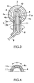
- FIG. 3 is a sectional view along line A-A in FIG. 1 and shows interior structure with the rear housing 4, the bushing 6 and so on.
- the rear housing 4 is formed, in the illustrated state, to be in a reverse U shape, and is provided at a tip end section with a cover 10.
- This cover 10 is one for hiding, so as not to be seen, a head of a screw (not shown) fixing the rear housing 4 to the front housing 2.
- a shaft 11 of a cylindrical shape is provided.
- a hook-shaped engaging section 11a is provided and, at its lower part, a recessed section 11b is formed.
- a stepped section 4a provided on the inner periphery of the rear housing 4 is formed in a shape substantially fitting to the engaging section 11a and recessed section 11b, and is made to engage in the recessed section 11b and to rotatably support the engaging section 11a, so that the shaft 11 will not be pulled out downward. Further, the bushing 6 is provided through a ring 5 on the outer periphery at lower half of the shaft 11.
- a body 5a of the ring 5 is rotatably provided in a space section 4b formed between the outer periphery of the shaft 11 and the lower inner periphery of the rear housing 4.
- Lower section of the ring 5 is of a shape bent toward outside and, at lower part of such bent section 5b, an upper section of the bushing 6 is mounted.
- this bushing 6 contacts the outer periphery of the shaft 11, and the bushing 6 is made rotatable in a predetermined range as shown by an arrow, together with the shaft 11 and the ring 5. This is for the reason that, if the bushing 6 is allowed to freely rotate by 360 degrees, there arises such risk that the cord is twisted to be damaged or broken.
- FIG. 4 is a structural example for allowing the bushing 6 to be ratatable only by a predetermined range.
- a guide groove 4c in a part of the inner periphery of the rear housing 4, and providing a projection type stopper 11c on the outer periphery of the shaft 11 to be shiftable within the guide groove 4c, the shaft 11 and eventually ring 5 and bushing 6 can be made rotatable with respect to the rear housing 4 by the predetermined range A. It is possible, of course, to employ another means so as to attain the rotation in the predetermined range.
- the predetermined range A means the range between the position of the hang down state and the position of the ear hanging state of the cord 9.
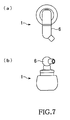
- FIG. 5 (a) is a front view of the earphone 1, (b) shows a state as viewed from a lower position of the state (a), and FIGS. 5 (a) and (b) through FIGS. 7 (a) and (b) show rotating states of the bushing 6.
- FIGS. 5 (a) and (b) are referred to as being of the cord's hang down state, for example, FIGS. 7 (a) and (b) will be of the cord's ear hanging state.
- FIG. 8 is a state of the earphone 1 inserted in the hole of ear 12 with the cord 9 in the hang down mode.
- 12a is the tragus.
- FIG. 9 shows a case where the direction of the earphone 1 is rotated toward upper side of the ear 12, and the bushing 6 is rotated to render the cord 9 to be in the ear hanging state.
- the earphone can be used in either type of the hang down state or the ear hanging state of the cord, and the mounting state of the earphone 1 with respect to the ear can be easily selected properly as required.
- This invention relates to the earphone which allows the one to personally listen to music and the like.
- the cord To the earphone, there is provided the cord.
- the earphone to which the present invention relates can be used in either of the hang down state or the ear hanging state of the cord, and the user can select the using state in accordance with circumstances with the cord made not in the way, so that the handiness of the earphone has been improved.
Landscapes
- Physics & Mathematics (AREA)
- Engineering & Computer Science (AREA)
- Acoustics & Sound (AREA)
- Signal Processing (AREA)
- Headphones And Earphones (AREA)
Abstract
Description
- This invention relates to earphones for listening to music and the like as mounted to ears.
- The earphones are used by inserting ear pad section of the earphone in an ear hole, while holding earphone housing by means of the tragus and antitragus of the ear. In this case, the earphone is provided at its lower part with a bushing, of which a cord is led out, and this cord is normally hanging down in the case when mounted (hereinafter referred to as "hang down state").
- Non-Patent Publication 1: Japanese Design Registration No.
1336084 - However, there have been problems that, during the use, the cord in the hang down state is caused when the user turns downward, for example, to hang down in front of his face, so as to be an eyesore, and to be in the way, and further that the cord swings to be annoying when the user is walking at quick pace or running.
- While these problems may be improved when the cord is put on the ear, there arises even in such case a problem that a stress may be imposed on the cord if the cord is forcibly pulled about the ear and the cord may easily slip away from the ear.
- This invention has been proposed in view of the above respects, and its object is to provide an earphone which can be used with its using mode selected to be excellent in the handiness, such that, in response to the user's using state or to the user's taste, the cord can be easily replaced optionally from the normal hang down state to an ear hanging state or, oppositely, from the ear hanging state to the hang down state.
- The invention of
claim 1 is an earphone having afront housing 2 provided in the interior with adriver unit 8, anear pad 3 covering as fitted to front outer peripheral part of said front housing, arear housing 4 provided on the back of saidfront housing 2, abushing 6 provided to saidrear housing 4 and having at lower end part a cord lead-outsection 6a, and acord 9 led out of said cord lead-outsection 6a of saidbushing 6; and characterized in that said bushing 6 is rotatable.
The invention ofclaim 2 is, in the earphone disclosed inclaim 1, further characterized in that there is provided within saidrear housing 4 arotatable shaft 11, said bushing 6 being engaged with theshaft 11, and saidshaft 11 and bushing 6 are rotatable.
The invention ofclaim 3 is, in the earphone disclosed inclaim 1, characterized in that said bushing 6 of which said cord is led out is rotatable within a range between a hang down state and an ear hanging state of thecord 9. - According to this invention, the bushing that having the cord is made rotatable, so that the earphone can be used in either one of the hang down state of the cord and the ear hanging state of the cord. Further, as the user can optionally and easily shift the cord from the normal hang down state to the ear hanging state or vice versa, it is possible to attain the earphone that can obtain a comfortable mounting feeling and can be excellent in the handiness.
-
- [
FIG. 1 ] A side view in an embodiment of the earphone according to the present invention is shown. - [
FIG. 2 ] A fragmentally and summarized sectional view of the earphone in the embodiment of the earphone according to the present invention is shown. - [
FIG. 3 ] A sectioned view along line A-A inFIG. 1 is shown. - [
FIG. 4 ] An example of arrangement for allowing the bushing to be rotated within a predetermined range is shown... - [
FIG. 5 ] (a) and (b) show a state in which the bushing is rotated, (a) being a front view, and (b) being its bottom view. - [
FIG 6 ] (a) shows a front view of the bushing in its rotating process, and (b) shows its bottom view. - [
FIG, 7 ] (a) shows a front view of the bushing in its state rotated on the side opposite toFIG. 5 , and (b) shows its bottom view. - [
FIG. 8 ] The earphone according to the present invention as mounted to the ear with the cord made in the hang down state is shown. - [
FIG. 9 ] The earphone according to the present invention in the ear hanging state is shown. -
- 1
- earphone
- 2
- front housing
- 2a
- front housing rear section
- 3
- ear pad
- 3a
- inside part
- 3b
- space section
- 3c
- outside part
- 3c'
- outside part front section
- 4
- rear housing
- 4a
- stepped section
- 4b
- space section
- 4c
- guide groove
- 5
- ring
- 5a
- ring body
- 5b
- ring bent section
- 6
- bushing
- 6a
- cord lead-out section
- 7
- protect screen
- 8
- driver unit
- 9
- cord
- 10
- cover
- 11
- shaft
- 11a
- engaging section
- 11b
- recessed section
- 11c
- stopper
- In the followings, an embodiment of the present invention shall be explained with reference to the drawings.
-
FIG. 1 is a side view of the earphone of the present invention, andFIG. 2 is a fragmentary summarized sectional view of the earphone of the present invention. - First, in
FIG. 1, 1 denotes the earphone, and thisearphone 1 consists of a hollowfront housing 2 made of a resin or metal, anear pad 3 covering an outer side at front part of thefront housing 2 and made of a soft and elastic material, arear housing 4 coupled to arear section 2a of thefront housing 2, and abushing 6 provided through aring 5 to lower section of therear housing 4 to be rotatable as shown by an arrow. 6a is a cord lead-out section, and 9 is a cord. - As shown in
FIG. 2 , theear pad 3 forms a double structure of aninside part 3a and anoutside part 3c the latter of which is positioned outer side of theinside part 3a through aspace section 3b. The reason why such double structure with thespace section 3b interposed is that theoutside part 3c can easily attain its elastic deformation when inserted into the ear hole, and further can easily deform along the shape of the ear hole to be excellent in the feeling with the earphone mounted. - Outer periphery of the
front housing 2 is covered by theinside part 3a of theear pad 3, while thefront section 3c' of theoutside part 3c is formed into a shape bent toward the side of thefront housing 2 so as to cover front section of thefront housing 2. Provided that, in this case, a recessedsection 2b is formed in a part of the outer periphery of thefront housing 2, theear pad 3 becomes preferably hard to be detached. By the way, the position of the recessedsection 2b should not be limited to the state illustrated. Further, if theinside part 3a of theear pad 3 is made to closely cover the outer periphery of thefront housing 2 so as not to slip off, the recessedpart 2b may not be specifically required. - At the front section inside the
front housing 2, aprotect screen 7 is provided, and adriver unit 8 including a diaphragm and a magnetic circuit for driving the diaphragm is provided on rear side of theprotect screen 7. As the arrangement ofsuch driver unit 8 is well known, its interior structure shall be omitted. 9 is a cord connected at one end to a voice coil (not shown) of thedriver unit 8 for supplying audio signals. The other end of thecord 9 is led out to therear housing 4 through a cylindricalrear section 2a formed at rear part of thefront housing 2 and to be of a diameter smaller than body part of thefront housing 2, and is exposed to the exterior from the cord lead-outsection 6a shown inFIG. 1 . -
FIG. 3 is a sectional view along line A-A inFIG. 1 and shows interior structure with therear housing 4, thebushing 6 and so on. - The
rear housing 4 is formed, in the illustrated state, to be in a reverse U shape, and is provided at a tip end section with acover 10. Thiscover 10 is one for hiding, so as not to be seen, a head of a screw (not shown) fixing therear housing 4 to thefront housing 2. Further, in therear housing 4, ashaft 11 of a cylindrical shape is provided. At an upper, outer peripheral section of thisshaft 11, a hook-shapedengaging section 11a is provided and, at its lower part, a recessedsection 11b is formed. A steppedsection 4a provided on the inner periphery of therear housing 4 is formed in a shape substantially fitting to the engagingsection 11a and recessedsection 11b, and is made to engage in the recessedsection 11b and to rotatably support the engagingsection 11a, so that theshaft 11 will not be pulled out downward. Further, thebushing 6 is provided through aring 5 on the outer periphery at lower half of theshaft 11. - A
body 5a of thering 5 is rotatably provided in aspace section 4b formed between the outer periphery of theshaft 11 and the lower inner periphery of therear housing 4. Lower section of thering 5 is of a shape bent toward outside and, at lower part of suchbent section 5b, an upper section of thebushing 6 is mounted. - The inner periphery of this
bushing 6 contacts the outer periphery of theshaft 11, and thebushing 6 is made rotatable in a predetermined range as shown by an arrow, together with theshaft 11 and thering 5. This is for the reason that, if thebushing 6 is allowed to freely rotate by 360 degrees, there arises such risk that the cord is twisted to be damaged or broken. -
FIG. 4 is a structural example for allowing thebushing 6 to be ratatable only by a predetermined range. By forming aguide groove 4c in a part of the inner periphery of therear housing 4, and providing aprojection type stopper 11c on the outer periphery of theshaft 11 to be shiftable within theguide groove 4c, theshaft 11 and eventually ring 5 andbushing 6 can be made rotatable with respect to therear housing 4 by the predetermined range A. It is possible, of course, to employ another means so as to attain the rotation in the predetermined range. - The predetermined range A means the range between the position of the hang down state and the position of the ear hanging state of the
cord 9. -
FIG. 5 (a) is a front view of theearphone 1, (b) shows a state as viewed from a lower position of the state (a), andFIGS. 5 (a) and (b) throughFIGS. 7 (a) and (b) show rotating states of thebushing 6. WhenFIGS. 5 (a) and (b) are referred to as being of the cord's hang down state, for example,FIGS. 7 (a) and (b) will be of the cord's ear hanging state. -
FIG. 8 is a state of theearphone 1 inserted in the hole ofear 12 with thecord 9 in the hang down mode. In the drawing, 12a is the tragus. -
FIG. 9 shows a case where the direction of theearphone 1 is rotated toward upper side of theear 12, and thebushing 6 is rotated to render thecord 9 to be in the ear hanging state. - According to the present invention, as in the foregoing, the earphone can be used in either type of the hang down state or the ear hanging state of the cord, and the mounting state of the
earphone 1 with respect to the ear can be easily selected properly as required. - This invention relates to the earphone which allows the one to personally listen to music and the like. To the earphone, there is provided the cord. The earphone to which the present invention relates can be used in either of the hang down state or the ear hanging state of the cord, and the user can select the using state in accordance with circumstances with the cord made not in the way, so that the handiness of the earphone has been improved.
Claims (3)
- An earphone, having:a front housing (2) provided in the interior with a driver unit (8),an ear pad (3) covering as fitted to front outer peripheral part of said front housing (2),a rear housing (4) provided on the back of said front housing (2),a bushing (6) provided to said rear housing (4) and having at lower end part a cord lead-out section (6a), anda cord (9) led out of said cord lead-out section (6a) of said bushing (6);wherein said bushing (6) is rotatable.
- The earphone disclosed in claim 1, which further having:a rotatable shaft (11) provided within said rear housing (4);wherein said bushing (6) is engaged with said shaft (11), and said shaft (11) and said bushing (6) are rotatable.
- The earphone disclosed in claim 1, characterized in that
said bushing (6) of which said cord (9) is led out is rotatable within a range between a hang down state and an ear hanging state of the cord (9).
Applications Claiming Priority (2)
| Application Number | Priority Date | Filing Date | Title |
|---|---|---|---|
| JP2008247455A JP4333885B1 (en) | 2008-09-26 | 2008-09-26 | earphone |
| PCT/JP2008/073310 WO2010035358A1 (en) | 2008-09-26 | 2008-12-22 | Earphone |
Publications (2)
| Publication Number | Publication Date |
|---|---|
| EP2328357A1 true EP2328357A1 (en) | 2011-06-01 |
| EP2328357A4 EP2328357A4 (en) | 2013-08-14 |
Family
ID=41190668
Family Applications (1)
| Application Number | Title | Priority Date | Filing Date |
|---|---|---|---|
| EP08877086.2A Withdrawn EP2328357A4 (en) | 2008-09-26 | 2008-12-22 | HEADSET |
Country Status (4)
| Country | Link |
|---|---|
| US (1) | US20110211724A1 (en) |
| EP (1) | EP2328357A4 (en) |
| JP (1) | JP4333885B1 (en) |
| WO (1) | WO2010035358A1 (en) |
Families Citing this family (15)
| Publication number | Priority date | Publication date | Assignee | Title |
|---|---|---|---|---|
| US8175315B2 (en) * | 2007-08-08 | 2012-05-08 | Victor Company Of Japan, Ltd. | Headphone set and method of producing the same |
| US8401218B2 (en) | 2010-07-29 | 2013-03-19 | Microsoft Corporation | Adjustable earphone and earphone set |
| JP2012074850A (en) * | 2010-09-28 | 2012-04-12 | Jvc Kenwood Corp | Headphone |
| JP6115187B2 (en) * | 2013-02-28 | 2017-04-19 | 株式会社Jvcケンウッド | headphone |
| WO2014162407A1 (en) * | 2013-04-01 | 2014-10-09 | パイオニア株式会社 | Earphone |
| WO2017004784A1 (en) * | 2015-07-07 | 2017-01-12 | 深圳市柔宇科技有限公司 | Ear muff |
| KR101814163B1 (en) * | 2016-07-20 | 2018-01-03 | (주)에스알커머스 | Customized earphone |
| US11307661B2 (en) | 2017-09-25 | 2022-04-19 | Apple Inc. | Electronic device with actuators for producing haptic and audio output along a device housing |
| EP3742752A4 (en) | 2018-01-19 | 2021-10-13 | Audio-Technica Corporation | WIRELESS HEADPHONES |
| US10757491B1 (en) | 2018-06-11 | 2020-08-25 | Apple Inc. | Wearable interactive audio device |
| US10873798B1 (en) * | 2018-06-11 | 2020-12-22 | Apple Inc. | Detecting through-body inputs at a wearable audio device |
| US11334032B2 (en) | 2018-08-30 | 2022-05-17 | Apple Inc. | Electronic watch with barometric vent |
| US11561144B1 (en) | 2018-09-27 | 2023-01-24 | Apple Inc. | Wearable electronic device with fluid-based pressure sensing |
| JP7194292B2 (en) | 2019-04-17 | 2022-12-21 | アップル インコーポレイテッド | radio localizable tag |
| US12256032B2 (en) | 2021-03-02 | 2025-03-18 | Apple Inc. | Handheld electronic device |
Family Cites Families (9)
| Publication number | Priority date | Publication date | Assignee | Title |
|---|---|---|---|---|
| JPS6032889U (en) * | 1983-08-12 | 1985-03-06 | 日本圧電気株式会社 | earphone ear hanging device |
| JPS6253890U (en) * | 1985-09-25 | 1987-04-03 | ||
| JPH0619272Y2 (en) * | 1987-06-15 | 1994-05-18 | 松下電器産業株式会社 | Headphone |
| US5412736A (en) * | 1992-03-23 | 1995-05-02 | Keliiliki; Shawn P. | Personal audio system and earphone for same |
| JP3254834B2 (en) * | 1993-08-06 | 2002-02-12 | 松下電器産業株式会社 | earphone |
| AU2003229240A1 (en) * | 2002-06-04 | 2003-12-19 | Adec And Partner Ag | Headset |
| US20060239447A1 (en) * | 2005-04-26 | 2006-10-26 | Shure Acquisition Holdings, Inc. | Earphone with selectable cable positioning |
| US8170262B1 (en) * | 2009-04-15 | 2012-05-01 | Frank Kung Fu Liu | Wireless air tube headset |
| US20120070028A1 (en) * | 2010-09-17 | 2012-03-22 | Steve Margulies | Earphone system, apparatus, and method for enhancing personal safety |
-
2008
- 2008-09-26 JP JP2008247455A patent/JP4333885B1/en active Active
- 2008-12-22 EP EP08877086.2A patent/EP2328357A4/en not_active Withdrawn
- 2008-12-22 WO PCT/JP2008/073310 patent/WO2010035358A1/en not_active Ceased
- 2008-12-22 US US12/737,968 patent/US20110211724A1/en not_active Abandoned
Also Published As
| Publication number | Publication date |
|---|---|
| US20110211724A1 (en) | 2011-09-01 |
| JP2010081306A (en) | 2010-04-08 |
| JP4333885B1 (en) | 2009-09-16 |
| WO2010035358A1 (en) | 2010-04-01 |
| EP2328357A4 (en) | 2013-08-14 |
Similar Documents
| Publication | Publication Date | Title |
|---|---|---|
| US20110211724A1 (en) | Earphone | |
| JP4088841B2 (en) | Inner earphone | |
| US7231056B2 (en) | Ear-hook earphone with microphone | |
| KR100955033B1 (en) | Earcap type wireless speaker device | |
| US20120243724A1 (en) | Ear pad and earphone having the same | |
| CN101374366A (en) | headphone device | |
| CN101322434A (en) | Earphone and method of using earphone | |
| US20160066079A1 (en) | Earphone with Interchangeable Housing | |
| JP6298337B2 (en) | Headphone device | |
| CN205081917U (en) | Many ear -hangs switch formula earphone | |
| KR101484182B1 (en) | earphone for ear canal adaptation | |
| JP2002034089A (en) | headphone | |
| CN206164779U (en) | Wear comfortable bluetooth headset | |
| JP2006005583A (en) | Earphone | |
| US20160066080A1 (en) | Earphone with Interchangeable Housing | |
| KR100703324B1 (en) | Ear Wearable Earsets | |
| CN205726296U (en) | A kind of earphone | |
| JP2011077762A (en) | Headphone device | |
| CN206164784U (en) | Bluetooth earphone | |
| JP6595370B2 (en) | Earphone with headband | |
| JP2017139523A (en) | headphone | |
| CN205545829U (en) | An earphone earhook and an earphone using the same | |
| CN222940890U (en) | Angle-adjustable open earphone | |
| KR200429813Y1 (en) | Earrings | |
| CN220067653U (en) | Angle-adjustable, ear-hanging neck-hanging interchangeable Bluetooth earphone structure |
Legal Events
| Date | Code | Title | Description |
|---|---|---|---|
| PUAI | Public reference made under article 153(3) epc to a published international application that has entered the european phase |
Free format text: ORIGINAL CODE: 0009012 |
|
| 17P | Request for examination filed |
Effective date: 20110225 |
|
| AK | Designated contracting states |
Kind code of ref document: A1 Designated state(s): AT BE BG CH CY CZ DE DK EE ES FI FR GB GR HR HU IE IS IT LI LT LU LV MC MT NL NO PL PT RO SE SI SK TR |
|
| AX | Request for extension of the european patent |
Extension state: AL BA MK RS |
|
| RIN1 | Information on inventor provided before grant (corrected) |
Inventor name: HIRATA, YASUHIRO |
|
| DAX | Request for extension of the european patent (deleted) | ||
| A4 | Supplementary search report drawn up and despatched |
Effective date: 20130717 |
|
| RIC1 | Information provided on ipc code assigned before grant |
Ipc: H04R 1/10 20060101AFI20130711BHEP |
|
| STAA | Information on the status of an ep patent application or granted ep patent |
Free format text: STATUS: THE APPLICATION IS DEEMED TO BE WITHDRAWN |
|
| 18D | Application deemed to be withdrawn |
Effective date: 20140213 |