EP2328250B1 - Circuit breaker control - Google Patents
Circuit breaker control Download PDFInfo
- Publication number
- EP2328250B1 EP2328250B1 EP10191933.0A EP10191933A EP2328250B1 EP 2328250 B1 EP2328250 B1 EP 2328250B1 EP 10191933 A EP10191933 A EP 10191933A EP 2328250 B1 EP2328250 B1 EP 2328250B1
- Authority
- EP
- European Patent Office
- Prior art keywords
- circuit breaker
- trip
- circuit
- circuit breakers
- breakers
- Prior art date
- Legal status (The legal status is an assumption and is not a legal conclusion. Google has not performed a legal analysis and makes no representation as to the accuracy of the status listed.)
- Active
Links
- 238000000034 method Methods 0.000 claims description 42
- 230000004224 protection Effects 0.000 claims description 32
- 230000004044 response Effects 0.000 claims description 12
- 230000008901 benefit Effects 0.000 description 4
- 230000009286 beneficial effect Effects 0.000 description 2
- 230000003111 delayed effect Effects 0.000 description 2
- 230000009977 dual effect Effects 0.000 description 2
- 230000007246 mechanism Effects 0.000 description 2
- 230000004048 modification Effects 0.000 description 2
- 238000012986 modification Methods 0.000 description 2
- 238000011144 upstream manufacturing Methods 0.000 description 2
- 230000004913 activation Effects 0.000 description 1
- 230000004075 alteration Effects 0.000 description 1
- 230000005540 biological transmission Effects 0.000 description 1
- 230000004907 flux Effects 0.000 description 1
- 238000006467 substitution reaction Methods 0.000 description 1
Images


Classifications
-
- H—ELECTRICITY
- H02—GENERATION; CONVERSION OR DISTRIBUTION OF ELECTRIC POWER
- H02H—EMERGENCY PROTECTIVE CIRCUIT ARRANGEMENTS
- H02H7/00—Emergency protective circuit arrangements specially adapted for specific types of electric machines or apparatus or for sectionalised protection of cable or line systems, and effecting automatic switching in the event of an undesired change from normal working conditions
- H02H7/26—Sectionalised protection of cable or line systems, e.g. for disconnecting a section on which a short-circuit, earth fault, or arc discharge has occured
- H02H7/261—Sectionalised protection of cable or line systems, e.g. for disconnecting a section on which a short-circuit, earth fault, or arc discharge has occured involving signal transmission between at least two stations
-
- G—PHYSICS
- G01—MEASURING; TESTING
- G01R—MEASURING ELECTRIC VARIABLES; MEASURING MAGNETIC VARIABLES
- G01R31/00—Arrangements for testing electric properties; Arrangements for locating electric faults; Arrangements for electrical testing characterised by what is being tested not provided for elsewhere
- G01R31/327—Testing of circuit interrupters, switches or circuit-breakers
- G01R31/3271—Testing of circuit interrupters, switches or circuit-breakers of high voltage or medium voltage devices
- G01R31/3272—Apparatus, systems or circuits therefor
-
- H—ELECTRICITY
- H02—GENERATION; CONVERSION OR DISTRIBUTION OF ELECTRIC POWER
- H02H—EMERGENCY PROTECTIVE CIRCUIT ARRANGEMENTS
- H02H7/00—Emergency protective circuit arrangements specially adapted for specific types of electric machines or apparatus or for sectionalised protection of cable or line systems, and effecting automatic switching in the event of an undesired change from normal working conditions
- H02H7/008—Emergency protective circuit arrangements specially adapted for specific types of electric machines or apparatus or for sectionalised protection of cable or line systems, and effecting automatic switching in the event of an undesired change from normal working conditions for protective arrangements according to this subclass
-
- Y—GENERAL TAGGING OF NEW TECHNOLOGICAL DEVELOPMENTS; GENERAL TAGGING OF CROSS-SECTIONAL TECHNOLOGIES SPANNING OVER SEVERAL SECTIONS OF THE IPC; TECHNICAL SUBJECTS COVERED BY FORMER USPC CROSS-REFERENCE ART COLLECTIONS [XRACs] AND DIGESTS
- Y02—TECHNOLOGIES OR APPLICATIONS FOR MITIGATION OR ADAPTATION AGAINST CLIMATE CHANGE
- Y02E—REDUCTION OF GREENHOUSE GAS [GHG] EMISSIONS, RELATED TO ENERGY GENERATION, TRANSMISSION OR DISTRIBUTION
- Y02E60/00—Enabling technologies; Technologies with a potential or indirect contribution to GHG emissions mitigation
-
- Y—GENERAL TAGGING OF NEW TECHNOLOGICAL DEVELOPMENTS; GENERAL TAGGING OF CROSS-SECTIONAL TECHNOLOGIES SPANNING OVER SEVERAL SECTIONS OF THE IPC; TECHNICAL SUBJECTS COVERED BY FORMER USPC CROSS-REFERENCE ART COLLECTIONS [XRACs] AND DIGESTS
- Y04—INFORMATION OR COMMUNICATION TECHNOLOGIES HAVING AN IMPACT ON OTHER TECHNOLOGY AREAS
- Y04S—SYSTEMS INTEGRATING TECHNOLOGIES RELATED TO POWER NETWORK OPERATION, COMMUNICATION OR INFORMATION TECHNOLOGIES FOR IMPROVING THE ELECTRICAL POWER GENERATION, TRANSMISSION, DISTRIBUTION, MANAGEMENT OR USAGE, i.e. SMART GRIDS
- Y04S10/00—Systems supporting electrical power generation, transmission or distribution
- Y04S10/16—Electric power substations
Definitions
- the subject matter disclosed herein relates to electrical circuit breakers, and more particularly, to circuit breaker control.
- US 2004/0130838 A1 discloses circuit breakers arranged in a layered, multi-leveled or multi-tiered configuration with a first upstream level of circuit breakers and a second level. In the event of a fault, the system attempts to clear the fault with the nearest circuit breaker upstream of the fault.
- electrical circuit breakers include a trip coil responsive to over-current events.
- the trip coil may "trip" if an over-current event exists.
- the trip coil may be responsive to trip signals of a trip unit.
- the trip coil may therefore also trip to open the circuit breaker in response to a trip signal.
- the trip signal may be initiated within the circuit breaker or transmitted to the circuit breaker from a central controller.
- the electrical circuit breakers may also include a shunt trip coil.
- the shunt trip coil may be a mechanical or electrical-mechanical trip coil.
- the shunt trip coil may trip if a mechanical linkage or trip lever is activated.
- the shunt trip coil may also be responsive to shunt trip signals of a trip unit. Therefore, the shunt trip coils may also trip in response to a shunt trip signal.
- the shunt trip signal may be initiated within the circuit breaker or transmitted to the circuit breaker from a central controller.
- the trip unit of the circuit breaker may sense the over-current condition, and attempt to open contacts of the circuit breaker. In situations where a relatively large current is flowing across the contacts of the circuit breaker, a large force may be necessary to open said contacts. If the trip coil does not provide enough force, the contacts may remain closed, and may allow the over-current condition to damage any components within the circuit of the circuit breaker.
- Shunt trip coils may provide a relatively larger force to open contacts of the circuit breaker.
- Shunt trip coils may be signal-tripped coils, over-voltage coils, under-voltage coils, and/or any combination thereof.
- shunt trip coils provide a relatively larger force than trip coils, there may be more power required to energize the shunt trip coil.
- a large number of shunt trip coils are energized at substantially the same time, a relatively significant amount of current is drawn.
- example embodiments provide methodologies of circuit breaker control taking into consideration any system power limitations in addition to coil operation.
- the present invention provides a circuit breaker protection system as defined in claim 1 and a method as defined in claim 11.
- a method of circuit breaker control includes determining if a trip event for a circuit breaker has occurred, determining a set of redundancy parameters for the circuit breaker, and transmitting a trip signal and a shunt trip signal to the circuit breaker based on the set of redundancy parameters.
- a method of circuit breaker control of a plurality of circuit breakers of a protection system includes determining a status of a first circuit breaker of the plurality of circuit breakers.
- the first circuit breaker's status is indicative of a pending trip signal associated with the first circuit breaker.
- the method further includes transmitting a trip signal to the first circuit breaker based on the first circuit breaker's status, establishing a priority of the first circuit breaker in response to the trip signal, and transmitting a shunt trip signal to the first circuit breaker based on the first circuit breaker's priority.
- a circuit breaker protection system includes a plurality of circuit breakers, each circuit breaker of the plurality of circuit breakers including a trip device and a shunt trip device, and a first central processor in communication with each circuit breaker of the plurality of circuit breakers.
- the first central processor is configured to perform a method of circuit breaker control including determining a status for each circuit breaker of the plurality of circuit breakers. Each circuit breaker's status is indicative of a pending trip signal associated with a respective circuit breaker.
- the method further includes transmitting a trip signal to each circuit breaker of the plurality of circuit breakers based on a respective circuit breaker's status, establishing a priority of each circuit breaker of the plurality of circuit breakers in response to a respective circuit breaker's trip signal, and transmitting a shunt trip signal to each circuit breaker of the plurality of circuit breakers based on a respective circuit breaker's priority.
- breaker refers to an electrical switching apparatus.
- the term breaker may be used interchangeably with electrical breaker, switching apparatus, circuit breaker, or any other suitable term referring to an arrangement of electrical contacts configured to interrupt an electrical current.
- network may refer to a communications network including a communication medium capable of transmitting electrical signals.
- node refers to a communication node configured, capable, and/or disposed to communicate with central processors and/or electrical circuit breakers.
- the communication node may further be configured, capable, and/or disposed to transmit an electrical signal indicative or a trip event to coils of the electrical circuit breakers.
- the communication node may, according to some example embodiments, be implemented as a trip unit or other suitable device.
- FIG. 1 is a system including circuit breaker control, according to an example embodiment.
- the system 100 includes two central processors, 101 and 102, executing a protection algorithm(s) configured to trip or open a plurality of circuit breakers based on protections events.
- the protection events may be transmitted to each central processor 101 and 102 individually or at substantially the same time.
- each processor may run the same protection algorithms as the other, so as to provide redundancy.
- the system 100 further includes nodes 103, 104, and 105.
- Each node 103, 104, and 105 may be a communications node disposed to communicate with central processors 101 and 102 over communication medium 110 and 120, respectively.
- the nodes 103, 104, and 105 may be trip units responsive to communications from the central processors 101 and 102.
- nodes 103, 104, and 105 may receive communications, signals, or command signals from the central processors 101 and 102, and transmit trip signals and shunt trip signals to circuit breakers.
- the communication mediums 110 and 120 may be Ethernet connections or any other suitable medium for transmitting command signals, command packets, or other similar signals/signal packets indicative of trip events.
- Trip events may be events in which a trip, or opening of a circuit breaker, are desired.
- an electrical trip signal may be established in/through the protection algorithm and transmitted to the particular circuit breaker such that one or both protection coils may be tripped (i.e., energized to open a set of contacts). Circuit breakers and protection coils are described more fully below.
- the system 100 may further include a plurality of circuit breakers 106, 107, and 108. Although only three circuit breakers are illustrated in FIG. 1 , it is understood that more or less circuit breakers may be included depending upon any particular application of example embodiments.
- Each circuit breaker 106, 107, and 108 may include at least two protection coils or devices (i.e., 161-162, 171-172, and 181-182).
- trip devices 161, 171, and 181 may be trip devices, which may further include trip coils. These trip coils may be flux shifter coils, current-sensing coils, and/or any other suitable protection coil.
- a trip coil may be energized in response to a trip event such that contacts (i.e., 164, 174, 184) of a circuit breaker are opened through an associated mechanism (i.e., 163, 173, 183) of the circuit breaker.
- Trip coils may also be energized in response to a trip signal transmitted to the trip device such that a circuit is effectively opened.
- Devices 162, 172, and 182 may be shunt trip devices, which may further include shunt trip coils.
- Shunt trip devices may be manual devices which may be tripped mechanically through mechanical linkages.
- Shunt trip coils may be voltage-sensing coils and/or manual trip coils, or other suitable protection coils responsive to activation manually with the shunt trip device or in response to a shunt trip signal.
- shunt trip coils may be energized in response to a shunt trip signal transmitted to the shunt trip device such that a circuit is effectively opened.
- Shunt trip coils may also be energized such that contacts (i.e., 164, 174, 184) of a circuit breaker are opened with greater force than a trip coil, through an associated mechanism (i.e., 163, 173, 183) of the circuit breaker.
- a shunt trip coil may be energized with about ten to about twelve amps.
- a shunt trip coil may also not provide enough force to effectively open contacts in some circumstances. For example, it may be desirable to energize both a trip coil and a shunt trip coil of a particular circuit breaker at substantially the same time, through use of both trip and shunt trip signals. Therefore, example embodiments provide redundant and/or dual coil operation.
- FIG. 2 is a flowchart of a method of circuit breaker control, according to an example embodiment.
- the method 200 includes catching a trip signal at block 201.
- a protection algorithm may determine a circuit breaker should be opened in response to a protection event (i.e. trip event).
- a central processor or other processor may issue an open commend/trip signal to a trip device of a circuit breaker.
- the trip signal may be caught through method 200 such that circuit breaker control may be established.
- the method 200 further includes determining redundancy parameters and/or if a predetermined condition exists at block 202.
- redundancy parameters may include power limitations, necessity of redundant and/or dual coil operation, concurrent trip coil open requests, and/or other suitable parameters.
- the predetermined condition may be a maximum or near-maximum number of shunt trip coils which may be energized at substantially the same time.
- the predetermined condition may also be a power limitation or other suitable condition.
- the method 200 further includes transmitting trip signal(s) based on the redundancy parameters.
- the signals may be limited to only trip signals.
- the signals may be delayed before transmission such that higher priority circuit breakers are tripped with both shunt trip and trip coils.
- existing shunt trip signals may be delayed if a higher priority trip signal has been caught. It is apparent that other scenarios may be applicable to circuit breaker control, therefore, a more detailed explanation of the methodologies of example embodiments is provided below with reference to FIGS. 3 and 4 .
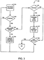
- FIG. 3 is a flowchart of a method of circuit breaker control, according to an example embodiment.
- the method 300 includes retrieving a circuit breaker at block 301.
- a plurality of circuit breakers may be included within a protection system.
- any number of the plurality of circuit breakers may be opened or closed.
- example methodologies may establish/determine a set of parameters which may be used to determine if a particular circuit breaker should be tripped.
- a circuit breaker i.e., status of a circuit breaker
- a circuit breaker i.e., status of a circuit breaker
- the method 300 further includes determining if the retrieved circuit breaker (i.e., monitored breaker) is included in a pending circuit breaker list (i.e., breakers not considered by method 300 already) at block 302. If the retrieved circuit breaker is not, the next circuit breaker is retrieved at block 301. If the retrieved circuit breaker is included in the pending circuit breaker list, the method 300 includes determining if the pending circuit breaker is in an open state, or a closed state at block 303.
- a pending circuit breaker list i.e., breakers not considered by method 300 already
- the circuit breaker is removed from the pending circuit breaker list at block 304, and the next circuit breaker is retrieved at block 301.
- the method 300 includes determining a status of the circuit breaker at block 305. For example, determining the status may include determining if a protection algorithm has requested the pending breaker be opened. For example, the status may be indicative of a pending trip signal associated with the circuit breaker. A pending trip signal may be a trip signal which has not yet been transmitted to an associated circuit breaker. If a protection algorithm has not requested the pending circuit breaker be opened (i.e., no pending trip signal), and the pending circuit breaker is not the last breaker in the system, the next circuit breaker is retrieved at block 301.
- the method 300 includes adding the pending circuit breaker to a circuit breaker list (i.e., breakers to be tripped with trip coils and shunt trip coils) at block 307, and determining if the pending circuit breaker is the last circuit breaker of the system to be retrieved at block 308.
- adding the pending circuit breaker to the circuit breaker list may include establishing a priority for the breaker and inserting the circuit breaker into the list based on its priority. This circuit breaker priority may be established based on predetermined parameters, a circuit breaker's location within a protection circuit with regards to other circuit breakers, a circuit breaker identification number, or other suitable parameters.
- the method 300 continues to the method 400 at block 401.
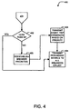
- FIG. 4 is a flowchart of a method of circuit breaker control, according to an example embodiment.
- the method 400 includes determining if a number of circuit breakers on a pending circuit breaker list is less than a number N at block 402.
- the number N may be a maximum or near-maximum number of shunt trip coils which may be energized at substantially the same time based on a predetermined condition (e.g., power, in-rush current, etc). If the number of circuit breakers on the pending circuit breaker list is not less than N, the method 400 includes transmitting trip signals and shunt trip signals to a group of circuit breakers of the pending circuit breaker list at block 405.
- the group of circuit breakers may be circuit breakers of a predetermined priority, and this group may satisfy a difference between the number N and the number of active shunt trip signals.
- the predetermined priority may be a range of priority values established based on protection system requirements, circuit breaker locations within a protection circuit, or other suitable parameters.
- the predetermined priority values may also be determined based on the maximum number of active shunt trip signals available to a protection system compared to the number of circuit breakers which have pending trip signals, and/or additionally compared to the criticality of a circuit breaker or location of a circuit breaker within the protection system.
- Circuit breakers of a predetermined priority may also be higher priority circuit breakers, sorted from highest priority to lowest priority. Thus, higher priority circuit breakers may be tripped first.
- the method 400 includes reestablishing priorities for each circuit breaker on the pending circuit breaker list at block 403.
- the reestablished priorities may be based on the criticality of each pending circuit breaker with regards to system protection. For example, feeder breakers may be considered less critical than breakers closer to, or dedicated to, critical system components. Therefore, higher priorities are established for more critical circuit breakers such that trip signals and shunt trip signals for these more critical (i.e., higher priority) circuit breakers are transmitted before less critical circuit breakers.
- the higher priorities are predetermined priorities based on criticality as described above.
- the method 400 includes transmitting shunt trip signals to activate shunt trip coils for the circuit breakers, based on circuit breaker priority, such that the total number of energized shunt trip coils is less than or equal to N at block 404.
Description
- The subject matter disclosed herein relates to electrical circuit breakers, and more particularly, to circuit breaker control.
-
US 2004/0130838 A1 discloses circuit breakers arranged in a layered, multi-leveled or multi-tiered configuration with a first upstream level of circuit breakers and a second level. In the event of a fault, the system attempts to clear the fault with the nearest circuit breaker upstream of the fault. - Generally, electrical circuit breakers include a trip coil responsive to over-current events. The trip coil may "trip" if an over-current event exists. Furthermore, the trip coil may be responsive to trip signals of a trip unit. The trip coil may therefore also trip to open the circuit breaker in response to a trip signal. The trip signal may be initiated within the circuit breaker or transmitted to the circuit breaker from a central controller. The electrical circuit breakers may also include a shunt trip coil. The shunt trip coil may be a mechanical or electrical-mechanical trip coil. The shunt trip coil may trip if a mechanical linkage or trip lever is activated. The shunt trip coil may also be responsive to shunt trip signals of a trip unit. Therefore, the shunt trip coils may also trip in response to a shunt trip signal. The shunt trip signal may be initiated within the circuit breaker or transmitted to the circuit breaker from a central controller.
- If an over-current event exists, the trip unit of the circuit breaker may sense the over-current condition, and attempt to open contacts of the circuit breaker. In situations where a relatively large current is flowing across the contacts of the circuit breaker, a large force may be necessary to open said contacts. If the trip coil does not provide enough force, the contacts may remain closed, and may allow the over-current condition to damage any components within the circuit of the circuit breaker.
- Shunt trip coils may provide a relatively larger force to open contacts of the circuit breaker. Shunt trip coils may be signal-tripped coils, over-voltage coils, under-voltage coils, and/or any combination thereof. However, as shunt trip coils provide a relatively larger force than trip coils, there may be more power required to energize the shunt trip coil. Thus if a large number of shunt trip coils are energized at substantially the same time, a relatively significant amount of current is drawn.
- Therefore, in scenarios where a limited of amount power is available or desirable, it may be beneficial to limit the number of shunt trip coils and trip coils energizing at substantially the same time. Furthermore, if predetermined conditions exist, for example large current flow conditions or other similar conditions, it may be beneficial to energize a shunt trip coil alongside a trip coil to increase the force applied to electrical contacts of a circuit breaker.
- Thus, example embodiments provide methodologies of circuit breaker control taking into consideration any system power limitations in addition to coil operation.
- The present invention provides a circuit breaker protection system as defined in
claim 1 and a method as defined in claim 11. - According to one example embodiment, a method of circuit breaker control includes determining if a trip event for a circuit breaker has occurred, determining a set of redundancy parameters for the circuit breaker, and transmitting a trip signal and a shunt trip signal to the circuit breaker based on the set of redundancy parameters.
- According to another example embodiment, a method of circuit breaker control of a plurality of circuit breakers of a protection system includes determining a status of a first circuit breaker of the plurality of circuit breakers. The first circuit breaker's status is indicative of a pending trip signal associated with the first circuit breaker. The method further includes transmitting a trip signal to the first circuit breaker based on the first circuit breaker's status, establishing a priority of the first circuit breaker in response to the trip signal, and transmitting a shunt trip signal to the first circuit breaker based on the first circuit breaker's priority.
- According to yet another example embodiment, a circuit breaker protection system includes a plurality of circuit breakers, each circuit breaker of the plurality of circuit breakers including a trip device and a shunt trip device, and a first central processor in communication with each circuit breaker of the plurality of circuit breakers. According to the example embodiments, the first central processor is configured to perform a method of circuit breaker control including determining a status for each circuit breaker of the plurality of circuit breakers. Each circuit breaker's status is indicative of a pending trip signal associated with a respective circuit breaker. The method further includes transmitting a trip signal to each circuit breaker of the plurality of circuit breakers based on a respective circuit breaker's status, establishing a priority of each circuit breaker of the plurality of circuit breakers in response to a respective circuit breaker's trip signal, and transmitting a shunt trip signal to each circuit breaker of the plurality of circuit breakers based on a respective circuit breaker's priority.
- These and other advantages and features will become more apparent from the following description taken in conjunction with the drawings.
- The subject matter, which is regarded as the invention, is particularly pointed out and distinctly claimed in the claims at the conclusion of the specification. The foregoing and other features, and advantages of the invention are apparent from the following detailed description taken in conjunction with the accompanying drawings in which:
-
FIG. 1 is a system including circuit breaker control, according to an example embodiment; -
FIG 2 is a flowchart of a method of circuit breaker control, according to an example embodiment; -
FIG 3 is a flowchart of a method of circuit breaker control, according to an example embodiment; and -
FIG. 4 is a flowchart of a method of circuit breaker control, according to an example embodiment. - The detailed description explains embodiments of the invention, together with advantages and features, by way of example with reference to the drawings.
- Detailed illustrative embodiments are disclosed herein. However, specific structural and functional details disclosed herein are merely representative for purposes of describing example embodiments. Example embodiments may, however, be embodied in many alternate forms and should not be construed as limited to only the embodiments set forth herein.
- Accordingly, while example embodiments are capable of various modifications and alternative forms, embodiments thereof are shown by way of example in the drawings and will herein be described in detail. It should be understood, however, that there is no intent to limit example embodiments to the particular forms disclosed, but to the contrary, example embodiments are to cover all modifications, equivalents, and alternatives falling within the scope of example embodiments. Like numbers refer to like elements throughout the description of the figures.
- It will be understood that, although the terms first, second, etc. may be used herein to describe various elements, these elements should not be limited by these terms. These terms are only used to distinguish one element from another. For example, a first element could be termed a second element, and, similarly, a second element could be termed a first element, without departing from the scope of example embodiments. As used herein, the term "and/or" includes any and all combinations of one or more of the associated listed items.
- As used herein, the singular forms "a", "an" and "the" are intended to include the plural forms as well, unless the context clearly indicates otherwise. It will be further understood that the terms "comprises", "comprising,", "includes" and/or "including", when used herein, specify the presence of stated features, integers, steps, operations, elements, and/or components, but do not preclude the presence or addition of one or more other features, integers, steps, operations, elements, components, and/or groups thereof.
- Furthermore, as used herein, the term breaker refers to an electrical switching apparatus. The term breaker may be used interchangeably with electrical breaker, switching apparatus, circuit breaker, or any other suitable term referring to an arrangement of electrical contacts configured to interrupt an electrical current.
- Moreover, the term network, as used herein, may refer to a communications network including a communication medium capable of transmitting electrical signals.
- Additionally, the term node refers to a communication node configured, capable, and/or disposed to communicate with central processors and/or electrical circuit breakers. The communication node may further be configured, capable, and/or disposed to transmit an electrical signal indicative or a trip event to coils of the electrical circuit breakers. Furthermore, the communication node may, according to some example embodiments, be implemented as a trip unit or other suitable device.
- Hereinafter, example embodiments of the present invention are described in detail with reference to
FIGS. 1-4 . -
FIG. 1 is a system including circuit breaker control, according to an example embodiment. Thesystem 100 includes two central processors, 101 and 102, executing a protection algorithm(s) configured to trip or open a plurality of circuit breakers based on protections events. The protection events may be transmitted to eachcentral processor - The
system 100 further includesnodes node central processors communication medium nodes central processors nodes central processors communication mediums - For example, if it is determined through a protection algorithm that a particular circuit breaker should be tripped, a trip event has occurred. Thus, an electrical trip signal may be established in/through the protection algorithm and transmitted to the particular circuit breaker such that one or both protection coils may be tripped (i.e., energized to open a set of contacts). Circuit breakers and protection coils are described more fully below.
- The
system 100 may further include a plurality ofcircuit breakers FIG. 1 , it is understood that more or less circuit breakers may be included depending upon any particular application of example embodiments. - Each
circuit breaker trip devices -
Devices -
FIG. 2 is a flowchart of a method of circuit breaker control, according to an example embodiment. Themethod 200 includes catching a trip signal atblock 201. For example, a protection algorithm may determine a circuit breaker should be opened in response to a protection event (i.e. trip event). Thus, a central processor or other processor may issue an open commend/trip signal to a trip device of a circuit breaker. The trip signal may be caught throughmethod 200 such that circuit breaker control may be established. - The
method 200 further includes determining redundancy parameters and/or if a predetermined condition exists atblock 202. For example, redundancy parameters may include power limitations, necessity of redundant and/or dual coil operation, concurrent trip coil open requests, and/or other suitable parameters. The predetermined condition may be a maximum or near-maximum number of shunt trip coils which may be energized at substantially the same time. The predetermined condition may also be a power limitation or other suitable condition. Themethod 200 further includes transmitting trip signal(s) based on the redundancy parameters. - For example, if a particular number of shunt trip coils and trip coils are being energized, the signals may be limited to only trip signals. Alternatively or in combination, the signals may be delayed before transmission such that higher priority circuit breakers are tripped with both shunt trip and trip coils. Also, existing shunt trip signals may be delayed if a higher priority trip signal has been caught. It is apparent that other scenarios may be applicable to circuit breaker control, therefore, a more detailed explanation of the methodologies of example embodiments is provided below with reference to
FIGS. 3 and4 . -
FIG. 3 is a flowchart of a method of circuit breaker control, according to an example embodiment. Themethod 300 includes retrieving a circuit breaker atblock 301. According to any given scenario, a plurality of circuit breakers may be included within a protection system. At any given time, any number of the plurality of circuit breakers may be opened or closed. As trip signals are caught (SeeFIG. 2 ), example methodologies may establish/determine a set of parameters which may be used to determine if a particular circuit breaker should be tripped. Accordingly, a circuit breaker (i.e., status of a circuit breaker) of the plurality of circuit breakers may be monitored/retrieved such that trip parameters may be determined. - The
method 300 further includes determining if the retrieved circuit breaker (i.e., monitored breaker) is included in a pending circuit breaker list (i.e., breakers not considered bymethod 300 already) atblock 302. If the retrieved circuit breaker is not, the next circuit breaker is retrieved atblock 301. If the retrieved circuit breaker is included in the pending circuit breaker list, themethod 300 includes determining if the pending circuit breaker is in an open state, or a closed state atblock 303. - If the pending circuit breaker is opened, the circuit breaker is removed from the pending circuit breaker list at
block 304, and the next circuit breaker is retrieved atblock 301. - If the circuit breaker is not in an open state, the
method 300 includes determining a status of the circuit breaker atblock 305. For example, determining the status may include determining if a protection algorithm has requested the pending breaker be opened. For example, the status may be indicative of a pending trip signal associated with the circuit breaker. A pending trip signal may be a trip signal which has not yet been transmitted to an associated circuit breaker. If a protection algorithm has not requested the pending circuit breaker be opened (i.e., no pending trip signal), and the pending circuit breaker is not the last breaker in the system, the next circuit breaker is retrieved atblock 301. - If a protection algorithm has requested the pending circuit breaker be opened (i.e., there is a pending trip signal), a trip signal to energize the trip coil of the circuit breaker is transmitted or set at
block 306. Thereafter, themethod 300 includes adding the pending circuit breaker to a circuit breaker list (i.e., breakers to be tripped with trip coils and shunt trip coils) atblock 307, and determining if the pending circuit breaker is the last circuit breaker of the system to be retrieved atblock 308. For example, adding the pending circuit breaker to the circuit breaker list may include establishing a priority for the breaker and inserting the circuit breaker into the list based on its priority. This circuit breaker priority may be established based on predetermined parameters, a circuit breaker's location within a protection circuit with regards to other circuit breakers, a circuit breaker identification number, or other suitable parameters. - If the pending circuit breaker is not the last circuit breaker of the system to be retrieved, the next circuit breaker is retrieved at
block 301. If the pending circuit breaker is the last circuit breaker in the system to be retrieved, themethod 300 continues to themethod 400 atblock 401. -
FIG. 4 is a flowchart of a method of circuit breaker control, according to an example embodiment. Themethod 400 includes determining if a number of circuit breakers on a pending circuit breaker list is less than a number N atblock 402. For example, the number N may be a maximum or near-maximum number of shunt trip coils which may be energized at substantially the same time based on a predetermined condition (e.g., power, in-rush current, etc). If the number of circuit breakers on the pending circuit breaker list is not less than N, themethod 400 includes transmitting trip signals and shunt trip signals to a group of circuit breakers of the pending circuit breaker list atblock 405. - The group of circuit breakers may be circuit breakers of a predetermined priority, and this group may satisfy a difference between the number N and the number of active shunt trip signals. The predetermined priority may be a range of priority values established based on protection system requirements, circuit breaker locations within a protection circuit, or other suitable parameters. The predetermined priority values may also be determined based on the maximum number of active shunt trip signals available to a protection system compared to the number of circuit breakers which have pending trip signals, and/or additionally compared to the criticality of a circuit breaker or location of a circuit breaker within the protection system. Circuit breakers of a predetermined priority may also be higher priority circuit breakers, sorted from highest priority to lowest priority. Thus, higher priority circuit breakers may be tripped first.
- If the number of circuit breakers on the pending circuit breakers list is less than N, the
method 400 includes reestablishing priorities for each circuit breaker on the pending circuit breaker list atblock 403. The reestablished priorities may be based on the criticality of each pending circuit breaker with regards to system protection. For example, feeder breakers may be considered less critical than breakers closer to, or dedicated to, critical system components. Therefore, higher priorities are established for more critical circuit breakers such that trip signals and shunt trip signals for these more critical (i.e., higher priority) circuit breakers are transmitted before less critical circuit breakers. The higher priorities are predetermined priorities based on criticality as described above. Thus, themethod 400 includes transmitting shunt trip signals to activate shunt trip coils for the circuit breakers, based on circuit breaker priority, such that the total number of energized shunt trip coils is less than or equal to N atblock 404. - As described above, according to example embodiments, methodologies of circuit breaker control are described which provide benefits with regard to breaker control.
- While the invention has been described in detail in connection with only a limited number of embodiments, it should be readily understood that the invention is not limited to such disclosed embodiments. Rather, the invention can be modified to incorporate any number of variations, alterations, substitutions or equivalent arrangements not heretofore described, but which are commensurate with the scope of the invention. Additionally, while various embodiments of the invention have been described, it is to be understood that aspects of the invention may include only some of the described embodiments. Accordingly, the invention is not to be seen as limited by the foregoing description, but is only limited by the scope of the appended claims.
Claims (14)
- A circuit breaker protection system (100), comprising:a plurality of circuit breakers (106, 107, 108), each circuit breaker (106) of the plurality of circuit breakers (106, 107, 108) including a trip device (161) and a shunt trip device (162); anda first central processor (101) in communication with each circuit breaker (106) of the plurality of circuit breakers (106, 107, 108), the first central processor (101) being configured to perform a method of circuit breaker control, the method comprising:determining a status (305) for each circuit breaker (106) of the plurality of circuit breakers (106, 107, 108), each circuit breaker's status being indicative of a pending trip signal associated with a respective circuit breaker (106);transmitting a trip signal (306) to each circuit breaker (106) of the plurality of circuit breakers (106, 107, 108) based on a respective circuit breaker's status;establishing a priority (307) of each circuit breaker (106) of the plurality of circuit breakers (106, 107, 108) in response to a respective circuit breaker's trip signal; andtransmitting a shunt trip signal (404, 405) to each circuit breaker (106) of the plurality of circuit breakers (106, 107, 108) based on a respective circuit breaker's priority.
- The system (100) of claim 1, wherein each circuit breaker's status is retrieved from a protection algorithm executed on the first central processor (101).
- The system (100) of claim 1 or claim 2, wherein each pending trip signal is established in a protection algorithm executed on the first central processor (101).
- The system (100) of any preceding claim, wherein each trip signal is transmitted to a respective trip device (161) of each circuit breaker (106).
- The system (100) of claim 4, wherein each trip device (161) of the plurality of circuit breakers (106, 107, 108) energizes a trip coil in response to a received trip signal.
- The system (100) of any preceding claim, further comprising a second central processor (102) in communication with each circuit breaker (106) of the plurality of circuit breakers (106, 107, 108), the second central processor (102) being configured to perform the method of circuit breaker control of the first central processor (101) redundantly.
- The system (100) of any preceding claim, further comprising a plurality of communication nodes (103, 104, 105), each communication node (103) of the plurality of communication nodes (103, 104, 105) being in communication with one circuit breaker of the plurality of circuit breakers (106, 107, 108), and the first central processor (101).
- The system (100) of claim 7, wherein each communication node (103) of the plurality of communication nodes (106, 107, 108) is a trip unit of a respective circuit breaker.
- The system (100) of any preceding claim, wherein the method of redundant breaker control further includes determining a number of active shunt trip signals (402) for the plurality of circuit breakers (106, 107, 108), and transmitting the shunt trip signals (404, 405) to circuit breakers of a predetermined priority based on the number of active shunt trip signals.
- The system of any preceding claim, wherein the method of redundant breaker control further includes determining if a predetermined condition exists (402) for the plurality of circuit breakers (106, 107, 108), transmitting the shunt trip signals (404, 405) to a group of circuit breakers of the plurality of circuit breakers (106, 107, 108) if the predetermined condition exists, the group of circuit breakers including circuit breakers of a predetermined priority, wherein the predetermined condition is a maximum number of active shunt trip signals of the protection system.
- A method of circuit breaker control of a plurality of circuit breakers of a protection system, the method comprising:determining a status for each circuit breaker of the plurality of circuit breakers, each circuit breaker's status being indicative of a pending trip signal associated with a respective circuit breaker;transmitting a trip signal to each circuit breaker of the plurality of circuit breakers based on a respective circuit breaker's status;establishing a priority for each circuit breaker of the plurality of circuit breakers in response to a respective circuit breaker's trip signal; andtransmitting a shunt trip signal to each circuit breaker of the plurality of circuit breakers based on a respective circuit breaker's priority.
- The method of claim 11, further comprising determining a status of electrical contacts of each circuit breaker, and transmitting the trip signal based on the electrical contacts' status.
- The method of claim 11 or claim 12, further comprising determining a number of active shunt trip signals of the plurality of breakers, and transmitting shunt trip signals to each breaker of the plurality of breakers based on the number of active shunt trip signals.
- The method of any of claims 11 to 13, further comprising determining if a predetermined condition exists for the plurality of circuit breakers, and transmitting the shunt trip signals to a group of circuit breakers of the plurality of circuit breakers if the predetermined condition exists.
Applications Claiming Priority (1)
| Application Number | Priority Date | Filing Date | Title |
|---|---|---|---|
| US12/628,135 US8189311B2 (en) | 2009-11-30 | 2009-11-30 | Circuit breaker control |
Publications (3)
| Publication Number | Publication Date |
|---|---|
| EP2328250A2 EP2328250A2 (en) | 2011-06-01 |
| EP2328250A3 EP2328250A3 (en) | 2012-09-19 |
| EP2328250B1 true EP2328250B1 (en) | 2016-03-30 |
Family
ID=43806945
Family Applications (1)
| Application Number | Title | Priority Date | Filing Date |
|---|---|---|---|
| EP10191933.0A Active EP2328250B1 (en) | 2009-11-30 | 2010-11-19 | Circuit breaker control |
Country Status (5)
| Country | Link |
|---|---|
| US (1) | US8189311B2 (en) |
| EP (1) | EP2328250B1 (en) |
| JP (1) | JP5639451B2 (en) |
| KR (1) | KR101766483B1 (en) |
| CN (1) | CN102082044B (en) |
Cited By (1)
| Publication number | Priority date | Publication date | Assignee | Title |
|---|---|---|---|---|
| CN108828438A (en) * | 2018-04-18 | 2018-11-16 | 国网江西省电力有限公司电力科学研究院 | Circuit-breaker status evaluation method |
Families Citing this family (7)
| Publication number | Priority date | Publication date | Assignee | Title |
|---|---|---|---|---|
| FR2987680B1 (en) * | 2012-03-05 | 2014-03-14 | Smartfuture | METHOD FOR MEASURING CURRENT IN AN ELECTRICITY NETWORK |
| CN103730885A (en) * | 2014-01-24 | 2014-04-16 | 兖州东方机电有限公司 | Power distribution device, protective system, mining power monitoring system and protection method |
| DE102015225243A1 (en) | 2015-06-24 | 2016-12-29 | Siemens Aktiengesellschaft | Electric switch |
| CN106444727A (en) * | 2016-11-30 | 2017-02-22 | 滁州学院 | Programmable lumped remote measurement and control device for smart miniature circuit breaker |
| KR102087143B1 (en) * | 2018-03-06 | 2020-03-10 | 엘에스산전 주식회사 | Protecting and interlocking system for plurality of circuit breakers in low voltage grid |
| CN109671595B (en) * | 2019-01-08 | 2020-01-14 | 程丽娜 | Switch |
| US11264767B2 (en) * | 2019-09-23 | 2022-03-01 | Eaton Intelligent Power Limited | Electrically interlocked receptacles in power pedestals |
Family Cites Families (12)
| Publication number | Priority date | Publication date | Assignee | Title |
|---|---|---|---|---|
| US5546265A (en) * | 1994-05-20 | 1996-08-13 | General Electric Company | Digital circuit interrupter shunt trip control circuit |
| US5808848A (en) * | 1997-02-21 | 1998-09-15 | General Electric Company | Digital circuit interrupter shunt trip accessory module |
| JP2000116034A (en) * | 1998-10-01 | 2000-04-21 | Hitachi Ltd | Monitor and control system for power system and control method |
| JP4044119B2 (en) * | 2000-03-15 | 2008-02-06 | 三菱電機株式会社 | System construction method |
| WO2003073572A2 (en) * | 2002-02-25 | 2003-09-04 | General Electric Company | Method and apparatus for optimized centralized critical control architecture for switchgear and power equipment |
| US7747354B2 (en) * | 2003-01-06 | 2010-06-29 | General Electric Company | Circuit protection system |
| DE102004015932A1 (en) | 2004-04-01 | 2005-10-20 | Moeller Gmbh | Method and circuit arrangement for operating a magnetic drive |
| US7525782B1 (en) * | 2005-03-31 | 2009-04-28 | The United States Of America As Represented By The United States Department Of Energy | Adaptive protection algorithm and system |
| JP2007028769A (en) * | 2005-07-14 | 2007-02-01 | Chugoku Electric Power Co Inc:The | Method for recovery from accident in distribution line system, and power distribution control device |
| JP2007288921A (en) * | 2006-04-17 | 2007-11-01 | Toshiba Corp | Switchgear controlling/monitoring system |
| KR100827674B1 (en) * | 2006-05-23 | 2008-05-07 | (주)한빛테크 | Automatic trip device for interrupting power and controlling method thereof |
| US7518475B2 (en) | 2007-07-24 | 2009-04-14 | Eaton Corporation | Electrical switching apparatus, circuit interrupter and method of interrupting overcurrents of a power circuit |
-
2009
- 2009-11-30 US US12/628,135 patent/US8189311B2/en active Active
-
2010
- 2010-11-19 EP EP10191933.0A patent/EP2328250B1/en active Active
- 2010-11-25 JP JP2010262060A patent/JP5639451B2/en active Active
- 2010-11-30 KR KR1020100120879A patent/KR101766483B1/en active IP Right Grant
- 2010-11-30 CN CN201010587128.4A patent/CN102082044B/en active Active
Cited By (1)
| Publication number | Priority date | Publication date | Assignee | Title |
|---|---|---|---|---|
| CN108828438A (en) * | 2018-04-18 | 2018-11-16 | 国网江西省电力有限公司电力科学研究院 | Circuit-breaker status evaluation method |
Also Published As
| Publication number | Publication date |
|---|---|
| KR20110060863A (en) | 2011-06-08 |
| JP2011120459A (en) | 2011-06-16 |
| US8189311B2 (en) | 2012-05-29 |
| CN102082044A (en) | 2011-06-01 |
| US20110127852A1 (en) | 2011-06-02 |
| KR101766483B1 (en) | 2017-08-08 |
| EP2328250A2 (en) | 2011-06-01 |
| CN102082044B (en) | 2014-08-13 |
| JP5639451B2 (en) | 2014-12-10 |
| EP2328250A3 (en) | 2012-09-19 |
Similar Documents
| Publication | Publication Date | Title |
|---|---|---|
| EP2328250B1 (en) | Circuit breaker control | |
| EP0948111B1 (en) | Fault protection arrangements and methods for electric power distribution systems | |
| US7751166B2 (en) | Advanced feeder architecture with automated power restoration | |
| US8213144B2 (en) | Circuit protection system | |
| EP2551983B1 (en) | System and method for protecting an electrical grid against faults | |
| US20040130837A1 (en) | Circuit protection system | |
| AU2014309019B2 (en) | Fast Switch Fault Current Limiter and Current Limiter System | |
| CN107433883B (en) | Railway traction power supply arm integrated monitoring system | |
| CN102340132B (en) | There is the protection system permitting logical energy model and regioselectivity of minimizing | |
| EP2909908B1 (en) | Method of operate is-limiters in ring systems | |
| CA2365737C (en) | Loop restoration scheme for distribution feeders | |
| US8861154B2 (en) | Recloser device and method of operation | |
| JP2011120459A5 (en) | ||
| EP2549609A2 (en) | Protection coordination system with current limiter | |
| EP2521151B1 (en) | Interlocked circuit breakers | |
| JP2011097797A (en) | Protection system of loop system | |
| CN106848996B (en) | Outlet protection method and device suitable for double-CPU structure | |
| Allen | Effects of wide-area control on the protection and operation of distribution networks | |
| CN107634499A (en) | A kind of double protection on-load switch fuse combined electric apparatus and circuit structure | |
| EP2651026B1 (en) | Automatic fault isolation methodology | |
| EP1939996A2 (en) | Method for coordination study for protective devices with dynamic settings, multiple functions and multiple setting groups | |
| KR20150048997A (en) | System for protective control of electric power system | |
| KR102515574B1 (en) | System for protrecting power system including superconducting fault current limiter and method for operating the same | |
| CN115579849A (en) | Method, device and equipment for processing switch latching fault and storage medium | |
| JP2000166084A (en) | Distribution system |
Legal Events
| Date | Code | Title | Description |
|---|---|---|---|
| PUAI | Public reference made under article 153(3) epc to a published international application that has entered the european phase |
Free format text: ORIGINAL CODE: 0009012 |
|
| AK | Designated contracting states |
Kind code of ref document: A2 Designated state(s): AL AT BE BG CH CY CZ DE DK EE ES FI FR GB GR HR HU IE IS IT LI LT LU LV MC MK MT NL NO PL PT RO RS SE SI SK SM TR |
|
| AX | Request for extension of the european patent |
Extension state: BA ME |
|
| PUAL | Search report despatched |
Free format text: ORIGINAL CODE: 0009013 |
|
| AK | Designated contracting states |
Kind code of ref document: A3 Designated state(s): AL AT BE BG CH CY CZ DE DK EE ES FI FR GB GR HR HU IE IS IT LI LT LU LV MC MK MT NL NO PL PT RO RS SE SI SK SM TR |
|
| AX | Request for extension of the european patent |
Extension state: BA ME |
|
| RIC1 | Information provided on ipc code assigned before grant |
Ipc: H02H 7/26 20060101AFI20120810BHEP |
|
| 17P | Request for examination filed |
Effective date: 20130319 |
|
| GRAP | Despatch of communication of intention to grant a patent |
Free format text: ORIGINAL CODE: EPIDOSNIGR1 |
|
| INTG | Intention to grant announced |
Effective date: 20151030 |
|
| GRAS | Grant fee paid |
Free format text: ORIGINAL CODE: EPIDOSNIGR3 |
|
| GRAA | (expected) grant |
Free format text: ORIGINAL CODE: 0009210 |
|
| AK | Designated contracting states |
Kind code of ref document: B1 Designated state(s): AL AT BE BG CH CY CZ DE DK EE ES FI FR GB GR HR HU IE IS IT LI LT LU LV MC MK MT NL NO PL PT RO RS SE SI SK SM TR |
|
| REG | Reference to a national code |
Ref country code: GB Ref legal event code: FG4D |
|
| REG | Reference to a national code |
Ref country code: CH Ref legal event code: EP |
|
| REG | Reference to a national code |
Ref country code: AT Ref legal event code: REF Ref document number: 786319 Country of ref document: AT Kind code of ref document: T Effective date: 20160415 |
|
| REG | Reference to a national code |
Ref country code: IE Ref legal event code: FG4D |
|
| REG | Reference to a national code |
Ref country code: DE Ref legal event code: R096 Ref document number: 602010031613 Country of ref document: DE |
|
| REG | Reference to a national code |
Ref country code: LT Ref legal event code: MG4D |
|
| PG25 | Lapsed in a contracting state [announced via postgrant information from national office to epo] |
Ref country code: HR Free format text: LAPSE BECAUSE OF FAILURE TO SUBMIT A TRANSLATION OF THE DESCRIPTION OR TO PAY THE FEE WITHIN THE PRESCRIBED TIME-LIMIT Effective date: 20160330 Ref country code: FI Free format text: LAPSE BECAUSE OF FAILURE TO SUBMIT A TRANSLATION OF THE DESCRIPTION OR TO PAY THE FEE WITHIN THE PRESCRIBED TIME-LIMIT Effective date: 20160330 Ref country code: GR Free format text: LAPSE BECAUSE OF FAILURE TO SUBMIT A TRANSLATION OF THE DESCRIPTION OR TO PAY THE FEE WITHIN THE PRESCRIBED TIME-LIMIT Effective date: 20160701 Ref country code: NO Free format text: LAPSE BECAUSE OF FAILURE TO SUBMIT A TRANSLATION OF THE DESCRIPTION OR TO PAY THE FEE WITHIN THE PRESCRIBED TIME-LIMIT Effective date: 20160630 |
|
| REG | Reference to a national code |
Ref country code: NL Ref legal event code: MP Effective date: 20160330 |
|
| REG | Reference to a national code |
Ref country code: AT Ref legal event code: MK05 Ref document number: 786319 Country of ref document: AT Kind code of ref document: T Effective date: 20160330 |
|
| PG25 | Lapsed in a contracting state [announced via postgrant information from national office to epo] |
Ref country code: LV Free format text: LAPSE BECAUSE OF FAILURE TO SUBMIT A TRANSLATION OF THE DESCRIPTION OR TO PAY THE FEE WITHIN THE PRESCRIBED TIME-LIMIT Effective date: 20160330 Ref country code: SE Free format text: LAPSE BECAUSE OF FAILURE TO SUBMIT A TRANSLATION OF THE DESCRIPTION OR TO PAY THE FEE WITHIN THE PRESCRIBED TIME-LIMIT Effective date: 20160330 Ref country code: LT Free format text: LAPSE BECAUSE OF FAILURE TO SUBMIT A TRANSLATION OF THE DESCRIPTION OR TO PAY THE FEE WITHIN THE PRESCRIBED TIME-LIMIT Effective date: 20160330 Ref country code: RS Free format text: LAPSE BECAUSE OF FAILURE TO SUBMIT A TRANSLATION OF THE DESCRIPTION OR TO PAY THE FEE WITHIN THE PRESCRIBED TIME-LIMIT Effective date: 20160330 |
|
| PG25 | Lapsed in a contracting state [announced via postgrant information from national office to epo] |
Ref country code: NL Free format text: LAPSE BECAUSE OF FAILURE TO SUBMIT A TRANSLATION OF THE DESCRIPTION OR TO PAY THE FEE WITHIN THE PRESCRIBED TIME-LIMIT Effective date: 20160330 |
|
| PG25 | Lapsed in a contracting state [announced via postgrant information from national office to epo] |
Ref country code: PL Free format text: LAPSE BECAUSE OF FAILURE TO SUBMIT A TRANSLATION OF THE DESCRIPTION OR TO PAY THE FEE WITHIN THE PRESCRIBED TIME-LIMIT Effective date: 20160330 Ref country code: EE Free format text: LAPSE BECAUSE OF FAILURE TO SUBMIT A TRANSLATION OF THE DESCRIPTION OR TO PAY THE FEE WITHIN THE PRESCRIBED TIME-LIMIT Effective date: 20160330 Ref country code: IS Free format text: LAPSE BECAUSE OF FAILURE TO SUBMIT A TRANSLATION OF THE DESCRIPTION OR TO PAY THE FEE WITHIN THE PRESCRIBED TIME-LIMIT Effective date: 20160730 |
|
| PG25 | Lapsed in a contracting state [announced via postgrant information from national office to epo] |
Ref country code: ES Free format text: LAPSE BECAUSE OF FAILURE TO SUBMIT A TRANSLATION OF THE DESCRIPTION OR TO PAY THE FEE WITHIN THE PRESCRIBED TIME-LIMIT Effective date: 20160330 Ref country code: SM Free format text: LAPSE BECAUSE OF FAILURE TO SUBMIT A TRANSLATION OF THE DESCRIPTION OR TO PAY THE FEE WITHIN THE PRESCRIBED TIME-LIMIT Effective date: 20160330 Ref country code: AT Free format text: LAPSE BECAUSE OF FAILURE TO SUBMIT A TRANSLATION OF THE DESCRIPTION OR TO PAY THE FEE WITHIN THE PRESCRIBED TIME-LIMIT Effective date: 20160330 Ref country code: PT Free format text: LAPSE BECAUSE OF FAILURE TO SUBMIT A TRANSLATION OF THE DESCRIPTION OR TO PAY THE FEE WITHIN THE PRESCRIBED TIME-LIMIT Effective date: 20160801 Ref country code: CZ Free format text: LAPSE BECAUSE OF FAILURE TO SUBMIT A TRANSLATION OF THE DESCRIPTION OR TO PAY THE FEE WITHIN THE PRESCRIBED TIME-LIMIT Effective date: 20160330 Ref country code: SK Free format text: LAPSE BECAUSE OF FAILURE TO SUBMIT A TRANSLATION OF THE DESCRIPTION OR TO PAY THE FEE WITHIN THE PRESCRIBED TIME-LIMIT Effective date: 20160330 Ref country code: RO Free format text: LAPSE BECAUSE OF FAILURE TO SUBMIT A TRANSLATION OF THE DESCRIPTION OR TO PAY THE FEE WITHIN THE PRESCRIBED TIME-LIMIT Effective date: 20160330 |
|
| PG25 | Lapsed in a contracting state [announced via postgrant information from national office to epo] |
Ref country code: BE Free format text: LAPSE BECAUSE OF FAILURE TO SUBMIT A TRANSLATION OF THE DESCRIPTION OR TO PAY THE FEE WITHIN THE PRESCRIBED TIME-LIMIT Effective date: 20160330 Ref country code: IT Free format text: LAPSE BECAUSE OF FAILURE TO SUBMIT A TRANSLATION OF THE DESCRIPTION OR TO PAY THE FEE WITHIN THE PRESCRIBED TIME-LIMIT Effective date: 20160330 |
|
| REG | Reference to a national code |
Ref country code: DE Ref legal event code: R097 Ref document number: 602010031613 Country of ref document: DE |
|
| PG25 | Lapsed in a contracting state [announced via postgrant information from national office to epo] |
Ref country code: DK Free format text: LAPSE BECAUSE OF FAILURE TO SUBMIT A TRANSLATION OF THE DESCRIPTION OR TO PAY THE FEE WITHIN THE PRESCRIBED TIME-LIMIT Effective date: 20160330 |
|
| PLBE | No opposition filed within time limit |
Free format text: ORIGINAL CODE: 0009261 |
|
| STAA | Information on the status of an ep patent application or granted ep patent |
Free format text: STATUS: NO OPPOSITION FILED WITHIN TIME LIMIT |
|
| 26N | No opposition filed |
Effective date: 20170103 |
|
| PG25 | Lapsed in a contracting state [announced via postgrant information from national office to epo] |
Ref country code: SI Free format text: LAPSE BECAUSE OF FAILURE TO SUBMIT A TRANSLATION OF THE DESCRIPTION OR TO PAY THE FEE WITHIN THE PRESCRIBED TIME-LIMIT Effective date: 20160330 |
|
| REG | Reference to a national code |
Ref country code: CH Ref legal event code: PL |
|
| GBPC | Gb: european patent ceased through non-payment of renewal fee |
Effective date: 20161119 |
|
| PG25 | Lapsed in a contracting state [announced via postgrant information from national office to epo] |
Ref country code: LI Free format text: LAPSE BECAUSE OF NON-PAYMENT OF DUE FEES Effective date: 20161130 Ref country code: CH Free format text: LAPSE BECAUSE OF NON-PAYMENT OF DUE FEES Effective date: 20161130 |
|
| REG | Reference to a national code |
Ref country code: IE Ref legal event code: MM4A |
|
| REG | Reference to a national code |
Ref country code: FR Ref legal event code: ST Effective date: 20170731 |
|
| PG25 | Lapsed in a contracting state [announced via postgrant information from national office to epo] |
Ref country code: LU Free format text: LAPSE BECAUSE OF NON-PAYMENT OF DUE FEES Effective date: 20161130 |
|
| PG25 | Lapsed in a contracting state [announced via postgrant information from national office to epo] |
Ref country code: FR Free format text: LAPSE BECAUSE OF NON-PAYMENT OF DUE FEES Effective date: 20161130 |
|
| PG25 | Lapsed in a contracting state [announced via postgrant information from national office to epo] |
Ref country code: GB Free format text: LAPSE BECAUSE OF NON-PAYMENT OF DUE FEES Effective date: 20161119 Ref country code: IE Free format text: LAPSE BECAUSE OF NON-PAYMENT OF DUE FEES Effective date: 20161119 |
|
| PG25 | Lapsed in a contracting state [announced via postgrant information from national office to epo] |
Ref country code: HU Free format text: LAPSE BECAUSE OF FAILURE TO SUBMIT A TRANSLATION OF THE DESCRIPTION OR TO PAY THE FEE WITHIN THE PRESCRIBED TIME-LIMIT; INVALID AB INITIO Effective date: 20101119 Ref country code: CY Free format text: LAPSE BECAUSE OF FAILURE TO SUBMIT A TRANSLATION OF THE DESCRIPTION OR TO PAY THE FEE WITHIN THE PRESCRIBED TIME-LIMIT Effective date: 20160330 |
|
| PG25 | Lapsed in a contracting state [announced via postgrant information from national office to epo] |
Ref country code: MK Free format text: LAPSE BECAUSE OF FAILURE TO SUBMIT A TRANSLATION OF THE DESCRIPTION OR TO PAY THE FEE WITHIN THE PRESCRIBED TIME-LIMIT Effective date: 20160330 Ref country code: MC Free format text: LAPSE BECAUSE OF FAILURE TO SUBMIT A TRANSLATION OF THE DESCRIPTION OR TO PAY THE FEE WITHIN THE PRESCRIBED TIME-LIMIT Effective date: 20160330 Ref country code: TR Free format text: LAPSE BECAUSE OF FAILURE TO SUBMIT A TRANSLATION OF THE DESCRIPTION OR TO PAY THE FEE WITHIN THE PRESCRIBED TIME-LIMIT Effective date: 20160330 |
|
| PG25 | Lapsed in a contracting state [announced via postgrant information from national office to epo] |
Ref country code: BG Free format text: LAPSE BECAUSE OF FAILURE TO SUBMIT A TRANSLATION OF THE DESCRIPTION OR TO PAY THE FEE WITHIN THE PRESCRIBED TIME-LIMIT Effective date: 20160330 |
|
| PG25 | Lapsed in a contracting state [announced via postgrant information from national office to epo] |
Ref country code: MT Free format text: LAPSE BECAUSE OF NON-PAYMENT OF DUE FEES Effective date: 20161119 |
|
| PG25 | Lapsed in a contracting state [announced via postgrant information from national office to epo] |
Ref country code: AL Free format text: LAPSE BECAUSE OF FAILURE TO SUBMIT A TRANSLATION OF THE DESCRIPTION OR TO PAY THE FEE WITHIN THE PRESCRIBED TIME-LIMIT Effective date: 20160330 |
|
| REG | Reference to a national code |
Ref country code: DE Ref legal event code: R081 Ref document number: 602010031613 Country of ref document: DE Owner name: ABB SCHWEIZ AG, CH Free format text: FORMER OWNER: GENERAL ELECTRIC CO., SCHENECTADY, N.Y., US |
|
| PGFP | Annual fee paid to national office [announced via postgrant information from national office to epo] |
Ref country code: DE Payment date: 20231121 Year of fee payment: 14 |