EP2327654A1 - Self-raising crane with structurally simplified locating means. - Google Patents
Self-raising crane with structurally simplified locating means. Download PDFInfo
- Publication number
- EP2327654A1 EP2327654A1 EP10189772A EP10189772A EP2327654A1 EP 2327654 A1 EP2327654 A1 EP 2327654A1 EP 10189772 A EP10189772 A EP 10189772A EP 10189772 A EP10189772 A EP 10189772A EP 2327654 A1 EP2327654 A1 EP 2327654A1
- Authority
- EP
- European Patent Office
- Prior art keywords
- crane
- self
- raising
- coupled
- upright columns
- Prior art date
- Legal status (The legal status is an assumption and is not a legal conclusion. Google has not performed a legal analysis and makes no representation as to the accuracy of the status listed.)
- Granted
Links
Images


Classifications
-
- B—PERFORMING OPERATIONS; TRANSPORTING
- B66—HOISTING; LIFTING; HAULING
- B66C—CRANES; LOAD-ENGAGING ELEMENTS OR DEVICES FOR CRANES, CAPSTANS, WINCHES, OR TACKLES
- B66C23/00—Cranes comprising essentially a beam, boom, or triangular structure acting as a cantilever and mounted for translatory of swinging movements in vertical or horizontal planes or a combination of such movements, e.g. jib-cranes, derricks, tower cranes
- B66C23/62—Constructional features or details
- B66C23/72—Counterweights or supports for balancing lifting couples
- B66C23/78—Supports, e.g. outriggers, for mobile cranes
-
- B—PERFORMING OPERATIONS; TRANSPORTING
- B66—HOISTING; LIFTING; HAULING
- B66C—CRANES; LOAD-ENGAGING ELEMENTS OR DEVICES FOR CRANES, CAPSTANS, WINCHES, OR TACKLES
- B66C23/00—Cranes comprising essentially a beam, boom, or triangular structure acting as a cantilever and mounted for translatory of swinging movements in vertical or horizontal planes or a combination of such movements, e.g. jib-cranes, derricks, tower cranes
- B66C23/18—Cranes comprising essentially a beam, boom, or triangular structure acting as a cantilever and mounted for translatory of swinging movements in vertical or horizontal planes or a combination of such movements, e.g. jib-cranes, derricks, tower cranes specially adapted for use in particular purposes
- B66C23/26—Cranes comprising essentially a beam, boom, or triangular structure acting as a cantilever and mounted for translatory of swinging movements in vertical or horizontal planes or a combination of such movements, e.g. jib-cranes, derricks, tower cranes specially adapted for use in particular purposes for use on building sites; constructed, e.g. with separable parts, to facilitate rapid assembly or dismantling, for operation at successively higher levels, for transport by road or rail
- B66C23/34—Self-erecting cranes, i.e. with hoisting gear adapted for crane erection purposes
-
- B—PERFORMING OPERATIONS; TRANSPORTING
- B66—HOISTING; LIFTING; HAULING
- B66C—CRANES; LOAD-ENGAGING ELEMENTS OR DEVICES FOR CRANES, CAPSTANS, WINCHES, OR TACKLES
- B66C23/00—Cranes comprising essentially a beam, boom, or triangular structure acting as a cantilever and mounted for translatory of swinging movements in vertical or horizontal planes or a combination of such movements, e.g. jib-cranes, derricks, tower cranes
- B66C23/18—Cranes comprising essentially a beam, boom, or triangular structure acting as a cantilever and mounted for translatory of swinging movements in vertical or horizontal planes or a combination of such movements, e.g. jib-cranes, derricks, tower cranes specially adapted for use in particular purposes
- B66C23/36—Cranes comprising essentially a beam, boom, or triangular structure acting as a cantilever and mounted for translatory of swinging movements in vertical or horizontal planes or a combination of such movements, e.g. jib-cranes, derricks, tower cranes specially adapted for use in particular purposes mounted on road or rail vehicles; Manually-movable jib-cranes for use in workshops; Floating cranes
Definitions
- the present invention relates to a self-raising crane with structurally simplified locating means.
- prior self-raising cranes conventionally comprise a crane bed to which a crane assembly including dedicated load raising and lowering means is coupled.
- the crane bed driving means for driving the bed with respect to the crane uprights, are very complex construction wise and very expensive which negatively affects the end cost of the crane.
- the aim of the present invention is to overcome the above mentioned drawbacks, by providing a self-raising crane including structurally simplified locating means and driving and raising assemblies, so designed as to provide the crane with a very low construction cost.
- a main object of the invention is to provide such a self-raising crane which may be easily conveyed to a use place or yard, and which, moreover, can be quickly and easily erected.
- Another object of the present invention is to provide such a self-raising crane which, owing to its specifically designed construction and features, is very reliable and safe in operation.
- Yet another object of the present invention is to provide such a self-raising crane, including structurally simplified locating means, which can be easily made starting from easily available elements and materials and which, moreover, is very competitive from a mere economic standpoint.
- a self-raising crane with structurally simplified locating means comprising a bearing construction including a plurality of arms coupled to a central framework and ending with guide seats engageable with upright columns, characterized in that said crane further comprises driving means for driving said bearing structure, said driving means being adapted to be removably coupled to and operate between said guide seats and upright columns.
- the self-raising crane including structurally simplified locating means, according to the invention, and which has been generally indicated by the reference number 1, comprises a bearing construction 2, including a central framework 3 which is connected to a base or bed element 4, including a plurality of rear wheels 5 and front steering wheels 6.
- a plurality of arms 11 which, at their free end portions, comprise guide seats or recesses 12 for engaging with upright columns 13, which may comprise a bearing base 14, of a not affixed to ground type and which, optionally, may be connected to means which are directly anchored to the ground.
- said arms 11 are bent on a side of the base framework whereas, in a use condition of the crane, as shown in figure 2 , strut elements 20 arranged between the arms and the base framework thereby arranging substantially at the vertex points of a square the four guide seats or recesses are herein provided.
- a crane assembly which, in a per se known manner, comprises a folding crane tower 31 and a crane boom 32, which may also be bent in a transport condition and may be arranged at a use position by conventional raising means, is arranged.
- inventive crane further comprises driving means, generally indicated by the reference number 40, which are removably coupled to the guide recesses or seats and to the upright columns.
- a fixed pin 41 and throughgoing holes 42 for engaging therein locking pegs 43 in turn engaged in coupling holes 44 formed on the upright columns 13 are provided.
- Said coupling holes 44 are designed for engaging therein coupling pins or pegs 45 allowing to connect a driving means 40 which, at the other end portion thereof is coupled to the fixed pin 41.
- said driving means are operated, which, in this embodiment, comprise a hydraulic cylinder but, in further embodiments, may also comprise worm screws, motor-reducer units, rack elements, rope or chain and pulley systems, to modify their length thereby allowing the crane bearing construction to be displaced with respect to the upright columns.
- the crane assembly is operatively driven and, upon having achieved the desired position, the locking pin 43 is again engaged to provide a proper position of the crane bed, which positioning may be obtained step by step.
- the fact is to be point out that the invention has provided a very simple and efficient crane construction which allows to quickly and economically locate the bearing construction.
- the invention provides to use several types of raising means which after operation can be easily removed.
- the used materials provided that they are compatible to the intended use, as well as the contingent size and shapes, can be any, depending on requirements.
Landscapes
- Engineering & Computer Science (AREA)
- Mechanical Engineering (AREA)
- Structural Engineering (AREA)
- Transportation (AREA)
- Jib Cranes (AREA)
Abstract
Description
- The present invention relates to a self-raising crane with structurally simplified locating means.
- As known, prior self-raising cranes conventionally comprise a crane bed to which a crane assembly including dedicated load raising and lowering means is coupled.
- In many situations, crane beds leaving free a space under the bed, thereby allowing traffic or the like to pass thereunder are used.
- In the above prior approaches, the crane bed driving means, for driving the bed with respect to the crane uprights, are very complex construction wise and very expensive which negatively affects the end cost of the crane.
- Accordingly, the aim of the present invention is to overcome the above mentioned drawbacks, by providing a self-raising crane including structurally simplified locating means and driving and raising assemblies, so designed as to provide the crane with a very low construction cost.
- Within the scope of the above mentioned aim, a main object of the invention is to provide such a self-raising crane which may be easily conveyed to a use place or yard, and which, moreover, can be quickly and easily erected.
- Another object of the present invention is to provide such a self-raising crane which, owing to its specifically designed construction and features, is very reliable and safe in operation.
- Yet another object of the present invention is to provide such a self-raising crane, including structurally simplified locating means, which can be easily made starting from easily available elements and materials and which, moreover, is very competitive from a mere economic standpoint.
- According to one aspect of the present invention, the above mentioned aim and objects, as well as yet other objects, which will become more apparent hereinafter, are achieved by a self-raising crane with structurally simplified locating means, comprising a bearing construction including a plurality of arms coupled to a central framework and ending with guide seats engageable with upright columns, characterized in that said crane further comprises driving means for driving said bearing structure, said driving means being adapted to be removably coupled to and operate between said guide seats and upright columns.
- Further characteristics and advantages of the present invention will become more apparent hereinafter from the following detailed disclosure of a preferred, though not exclusive, embodiment of the invention, which is illustrated, by way of an indicative, but not limitative, example in the accompanying drawings, where:
-
Figure 1 is a schematic top plan view of the self-raising crane according to the present invention, in a transport or shipment condition thereof; -
Figure 2 is a further top plan view of the inventive crane with its bearing framework at a use condition thereof; -
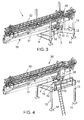
Figure 3 is a perspective view showing the self-raising crane according to the present invention in a lowered condition thereof; -
Figure 4 is a schematic view showing the self-raising crane according to the present invention with load bearing structure construction in a raised position or condition thereof; -
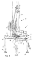
Figure 5 is a further schematic perspective view showing the inventive crane in a raised position thereof; -
Figure 6 is a side elevation view showing the inventive crane in a raised fully extended position thereof; -
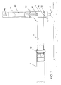
Figure 7 is a schematic view showing the crane driving means in a lowered position thereof; and -
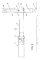
Figure 8 shows the crane driving means after having performed a first raising operation. - With reference to the number references of the above mentioned figures, the self-raising crane including structurally simplified locating means, according to the invention, and which has been generally indicated by the
reference number 1, comprises abearing construction 2, including acentral framework 3 which is connected to a base orbed element 4, including a plurality ofrear wheels 5 andfront steering wheels 6. - To said central framework or
body 3 are pivoted, so as to rotate or pivot aboutpivot pins 10 extending substantially perpendicular to the ground, a plurality ofarms 11 which, at their free end portions, comprise guide seats orrecesses 12 for engaging withupright columns 13, which may comprise abearing base 14, of a not affixed to ground type and which, optionally, may be connected to means which are directly anchored to the ground. - Under a transport or shipment condition, as shown in
figure 1 , saidarms 11 are bent on a side of the base framework whereas, in a use condition of the crane, as shown infigure 2 ,strut elements 20 arranged between the arms and the base framework thereby arranging substantially at the vertex points of a square the four guide seats or recesses are herein provided. - At said central framework or
body 3, a crane assembly, generally indicated by thereference number 30, which, in a per se known manner, comprises a foldingcrane tower 31 and acrane boom 32, which may also be bent in a transport condition and may be arranged at a use position by conventional raising means, is arranged. - On the base or
bed 35 of thetower 31counterweights 36 which are opposite to the crane boom, thereby operating as crane anti-tilting elements are moreover arranged. - A main feature of the invention is that the inventive crane further comprises driving means, generally indicated by the
reference number 40, which are removably coupled to the guide recesses or seats and to the upright columns. - More specifically, at said guide seats or recesses 12 a fixed
pin 41 and throughgoingholes 42 for engaging thereinlocking pegs 43 in turn engaged incoupling holes 44 formed on theupright columns 13 are provided. - Said
coupling holes 44 are designed for engaging therein coupling pins orpegs 45 allowing to connect adriving means 40 which, at the other end portion thereof is coupled to the fixedpin 41. - To drive or displace the bearing construction with respect to the upright columns, said driving means are operated, which, in this embodiment, comprise a hydraulic cylinder but, in further embodiments, may also comprise worm screws, motor-reducer units, rack elements, rope or chain and pulley systems, to modify their length thereby allowing the crane bearing construction to be displaced with respect to the upright columns.
- In operation, the crane assembly is operatively driven and, upon having achieved the desired position, the
locking pin 43 is again engaged to provide a proper position of the crane bed, which positioning may be obtained step by step. - After having brought to the desired level the bearing construction, it is possible to stabilize the overall structure by stabilizing
screws 50 arranged on the guide recesses orseats 12 and allowing to firmly clamp the upright columns to the related guide seats. - In this connection it should be pointed out that the raising of the crane is performed in a fully autonomous manner, that is without using outer machines.
- Thus, with the disclosed arrangement, it is possible, after having properly located the bearing structure or construction with respect to the upright columns, to remove the driving means which may be used at other building yards.
- From the above disclosure it should be apparent that the invention fully achieves the intended aim and objects.
- In particular, the fact is to be point out that the invention has provided a very simple and efficient crane construction which allows to quickly and economically locate the bearing construction.
- In fact, the invention provides to use several types of raising means which after operation can be easily removed.
- The invention as disclosed is susceptible to several modifications and variations, all of which will come within the scope of the inventive idea.
- Moreover, all the constructional details can be replaced by other technically equivalent elements.
- In practicing the invention, the used materials, provided that they are compatible to the intended use, as well as the contingent size and shapes, can be any, depending on requirements.
Claims (10)
- A self-raising crane with structurally simplified locating means, comprising a bearing construction including a plurality of arms coupled to a central framework and ending with guide seats engageable by upright columns, characterized in that said crane further comprises driving means for driving said bearing structure, said driving means being adapted to be removably coupled to and operate between said guide seats and upright columns.
- A self-raising crane, according to the preceding claim, characterized in that said bearing construction comprises a bottom element including a plurality of wheels and being coupled to said central framework.
- A self-raising crane, according to the preceding claims, characterized in that said bottom element comprises steering rear wheels and front wheels.
- A self-raising crane, according to one or more of the preceding claims, characterized in that each said arm is coupled to said central body so as to swing about a swinging axis substantially perpendicular to a bearing plane.
- A self-raising crane, according to one or more of the preceding claims, characterized in that said upright columns are coupled to supporting pyramidal elements not affixed to the ground.
- A self-raising crane, according to one or more of the preceding claims, characterized in that said upright columns are coupled to ground affixed plinth elements.
- A self-raising crane, according to one or more of the preceding claims, characterized in that said handling means comprise a plurality of hydraulic cylinders of a worm screw system and that said crane can be raised in an autonomous manner, without using outer raising machines.
- A self-raising crane, according to one or more of the preceding claims, characterized in that said handling means comprise a geared system.
- A self-raising crane, according to one or more of the preceding claims, characterized in that said handling means comprise a rack system and/or a rope or chain system including sheave or gear transmission means.
- A self-raising crane, according to one or more of the preceding claims, characterized in that said guide seats comprise thereon locking screws for stabilizing said guide seats with respect to said upright columns.
Applications Claiming Priority (1)
| Application Number | Priority Date | Filing Date | Title |
|---|---|---|---|
| ITMI2009A002096A IT1396632B1 (en) | 2009-11-27 | 2009-11-27 | AUTOMATIC CRANE WITH SIMPLIFIED POSITIONING MEANS. |
Publications (2)
| Publication Number | Publication Date |
|---|---|
| EP2327654A1 true EP2327654A1 (en) | 2011-06-01 |
| EP2327654B1 EP2327654B1 (en) | 2014-06-11 |
Family
ID=42272025
Family Applications (1)
| Application Number | Title | Priority Date | Filing Date |
|---|---|---|---|
| EP20100189772 Active EP2327654B1 (en) | 2009-11-27 | 2010-11-03 | Self-raising crane with structurally simplified locating means. |
Country Status (3)
| Country | Link |
|---|---|
| EP (1) | EP2327654B1 (en) |
| ES (1) | ES2498824T3 (en) |
| IT (1) | IT1396632B1 (en) |
Cited By (1)
| Publication number | Priority date | Publication date | Assignee | Title |
|---|---|---|---|---|
| EP3000763A1 (en) * | 2014-09-25 | 2016-03-30 | Konecranes Global Corporation | Self-deploying telescoping jib crane system |
Families Citing this family (1)
| Publication number | Priority date | Publication date | Assignee | Title |
|---|---|---|---|---|
| WO2025032264A1 (en) * | 2023-08-04 | 2025-02-13 | Elevall Gruas Slu | Portable lifting crane |
Citations (7)
| Publication number | Priority date | Publication date | Assignee | Title |
|---|---|---|---|---|
| US3035713A (en) * | 1958-10-03 | 1962-05-22 | United Equipment Accessories I | Full rotary truck mounted crane and bracing outriggers |
| US4619369A (en) * | 1984-03-15 | 1986-10-28 | Maschinenfabrik Walter Scheele Gmbh & Co. Kg | Support or stabilizer devices for mobile construction equipment |
| WO1996034782A1 (en) * | 1995-05-03 | 1996-11-07 | Hiab Forest Ab | Support leg |
| DE19856593A1 (en) * | 1997-12-09 | 1999-06-17 | Koeck Elke | Trailer system for transporting projecting loads, e.g. swiveling base, folding tower crane |
| CN1837012A (en) * | 2006-04-13 | 2006-09-27 | 梁毅 | Crane with double-power driven walking chassis |
| CN201292227Y (en) * | 2008-11-19 | 2009-08-19 | 三一汽车制造有限公司 | Front swing support of truck crane and truck crane having the same |
| DE102008058937A1 (en) * | 2008-05-21 | 2009-11-26 | Putzmeister Concrete Pumps Gmbh | Mobile implement with stability monitoring |
-
2009
- 2009-11-27 IT ITMI2009A002096A patent/IT1396632B1/en active
-
2010
- 2010-11-03 EP EP20100189772 patent/EP2327654B1/en active Active
- 2010-11-03 ES ES10189772.6T patent/ES2498824T3/en active Active
Patent Citations (7)
| Publication number | Priority date | Publication date | Assignee | Title |
|---|---|---|---|---|
| US3035713A (en) * | 1958-10-03 | 1962-05-22 | United Equipment Accessories I | Full rotary truck mounted crane and bracing outriggers |
| US4619369A (en) * | 1984-03-15 | 1986-10-28 | Maschinenfabrik Walter Scheele Gmbh & Co. Kg | Support or stabilizer devices for mobile construction equipment |
| WO1996034782A1 (en) * | 1995-05-03 | 1996-11-07 | Hiab Forest Ab | Support leg |
| DE19856593A1 (en) * | 1997-12-09 | 1999-06-17 | Koeck Elke | Trailer system for transporting projecting loads, e.g. swiveling base, folding tower crane |
| CN1837012A (en) * | 2006-04-13 | 2006-09-27 | 梁毅 | Crane with double-power driven walking chassis |
| DE102008058937A1 (en) * | 2008-05-21 | 2009-11-26 | Putzmeister Concrete Pumps Gmbh | Mobile implement with stability monitoring |
| CN201292227Y (en) * | 2008-11-19 | 2009-08-19 | 三一汽车制造有限公司 | Front swing support of truck crane and truck crane having the same |
Cited By (4)
| Publication number | Priority date | Publication date | Assignee | Title |
|---|---|---|---|---|
| EP3000763A1 (en) * | 2014-09-25 | 2016-03-30 | Konecranes Global Corporation | Self-deploying telescoping jib crane system |
| US10086739B2 (en) | 2014-09-25 | 2018-10-02 | Konecranes Global Corporation | Self-deploying telescoping jib crane system |
| US10513214B2 (en) | 2014-09-25 | 2019-12-24 | Konecranes Global Corporation | Self-deploying telescoping jib crane system |
| EP4095085A1 (en) * | 2014-09-25 | 2022-11-30 | Konecranes Global Corporation | Self-deploying telescoping jib crane system |
Also Published As
| Publication number | Publication date |
|---|---|
| EP2327654B1 (en) | 2014-06-11 |
| ES2498824T3 (en) | 2014-09-25 |
| IT1396632B1 (en) | 2012-12-14 |
| ITMI20092096A1 (en) | 2011-05-28 |
Similar Documents
| Publication | Publication Date | Title |
|---|---|---|
| ES2901487T5 (en) | Method for onshore or offshore erecting an upstanding construction | |
| US8011098B2 (en) | Wind turbine erector | |
| CN205688927U (en) | Base for a monopole and monopole structure | |
| EP1980710A2 (en) | Rig for drilling or maintaining oil wells | |
| ES2717257T3 (en) | Assembly system and assembly procedure of a wind turbine tower | |
| EP2585712A1 (en) | Lifting device and method for positioning of an unwieldy object | |
| JP6756518B2 (en) | How to operate the crane and the crane | |
| JP2017538881A (en) | Pile appending system | |
| US10526176B2 (en) | Crane assembling method | |
| EP2055362A1 (en) | Upright support structure for a fairground attraction, in particular a ferris wheel | |
| KR101358679B1 (en) | Hinge assembling apparatus for boom combination | |
| KR20120042115A (en) | Tower crane | |
| WO2018020056A1 (en) | System for the assembly/disassembly of blades in wind turbines | |
| KR20210025211A (en) | An electric gantry crane assembly | |
| CN102303821A (en) | Luffing tower crane with balanced type suspension arm based on traction luffing of steel rope | |
| WO2015158713A1 (en) | Mobile crane device and method for the temporary assembly of such a crane device | |
| KR20170132851A (en) | Cranes with gantry forces and boom forces that effectively coincide in the upper structure | |
| EP2327654B1 (en) | Self-raising crane with structurally simplified locating means. | |
| CN201722116U (en) | Plate lifter | |
| EP3942124B1 (en) | Tool arrangement for pivoting a tower or a tower segment from a non-erected position to an erected position | |
| KR101676457B1 (en) | radioactive waste disposal | |
| AU3161795A (en) | Crane for raising longitudinal bodies, foundation for such a crane and method for raising of longitudinal bodies by means of such a crane | |
| JP2017095259A (en) | Telescopic mechanism | |
| CN203903526U (en) | Livestock transportation gangplank | |
| KR101006401B1 (en) | Gangfoam lifting device |
Legal Events
| Date | Code | Title | Description |
|---|---|---|---|
| PUAI | Public reference made under article 153(3) epc to a published international application that has entered the european phase |
Free format text: ORIGINAL CODE: 0009012 |
|
| AK | Designated contracting states |
Kind code of ref document: A1 Designated state(s): AL AT BE BG CH CY CZ DE DK EE ES FI FR GB GR HR HU IE IS IT LI LT LU LV MC MK MT NL NO PL PT RO RS SE SI SK SM TR |
|
| AX | Request for extension of the european patent |
Extension state: BA ME |
|
| 17P | Request for examination filed |
Effective date: 20111129 |
|
| 17Q | First examination report despatched |
Effective date: 20120919 |
|
| REG | Reference to a national code |
Ref country code: DE Ref legal event code: R079 Ref document number: 602010016600 Country of ref document: DE Free format text: PREVIOUS MAIN CLASS: B66C0023780000 Ipc: B66C0023340000 |
|
| RIC1 | Information provided on ipc code assigned before grant |
Ipc: B66C 23/34 20060101AFI20131129BHEP Ipc: B66C 23/78 20060101ALI20131129BHEP Ipc: B66C 23/36 20060101ALI20131129BHEP |
|
| GRAP | Despatch of communication of intention to grant a patent |
Free format text: ORIGINAL CODE: EPIDOSNIGR1 |
|
| INTG | Intention to grant announced |
Effective date: 20140211 |
|
| GRAS | Grant fee paid |
Free format text: ORIGINAL CODE: EPIDOSNIGR3 |
|
| GRAA | (expected) grant |
Free format text: ORIGINAL CODE: 0009210 |
|
| AK | Designated contracting states |
Kind code of ref document: B1 Designated state(s): AL AT BE BG CH CY CZ DE DK EE ES FI FR GB GR HR HU IE IS IT LI LT LU LV MC MK MT NL NO PL PT RO RS SE SI SK SM TR |
|
| REG | Reference to a national code |
Ref country code: GB Ref legal event code: FG4D |
|
| REG | Reference to a national code |
Ref country code: CH Ref legal event code: EP |
|
| REG | Reference to a national code |
Ref country code: IE Ref legal event code: FG4D |
|
| REG | Reference to a national code |
Ref country code: AT Ref legal event code: REF Ref document number: 672154 Country of ref document: AT Kind code of ref document: T Effective date: 20140715 |
|
| REG | Reference to a national code |
Ref country code: DE Ref legal event code: R096 Ref document number: 602010016600 Country of ref document: DE Effective date: 20140717 |
|
| REG | Reference to a national code |
Ref country code: DE Ref legal event code: R082 Ref document number: 602010016600 Country of ref document: DE Representative=s name: LERMER, CHRISTOPH GEORG, DIPL.-PHYS. UNIV., DE Ref country code: CH Ref legal event code: NV Representative=s name: BOVARD AG, CH |
|
| REG | Reference to a national code |
Ref country code: ES Ref legal event code: FG2A Ref document number: 2498824 Country of ref document: ES Kind code of ref document: T3 Effective date: 20140925 |
|
| PG25 | Lapsed in a contracting state [announced via postgrant information from national office to epo] |
Ref country code: NO Free format text: LAPSE BECAUSE OF FAILURE TO SUBMIT A TRANSLATION OF THE DESCRIPTION OR TO PAY THE FEE WITHIN THE PRESCRIBED TIME-LIMIT Effective date: 20140911 Ref country code: FI Free format text: LAPSE BECAUSE OF FAILURE TO SUBMIT A TRANSLATION OF THE DESCRIPTION OR TO PAY THE FEE WITHIN THE PRESCRIBED TIME-LIMIT Effective date: 20140611 Ref country code: LT Free format text: LAPSE BECAUSE OF FAILURE TO SUBMIT A TRANSLATION OF THE DESCRIPTION OR TO PAY THE FEE WITHIN THE PRESCRIBED TIME-LIMIT Effective date: 20140611 Ref country code: GR Free format text: LAPSE BECAUSE OF FAILURE TO SUBMIT A TRANSLATION OF THE DESCRIPTION OR TO PAY THE FEE WITHIN THE PRESCRIBED TIME-LIMIT Effective date: 20140912 |
|
| REG | Reference to a national code |
Ref country code: NL Ref legal event code: VDEP Effective date: 20140611 |
|
| REG | Reference to a national code |
Ref country code: AT Ref legal event code: MK05 Ref document number: 672154 Country of ref document: AT Kind code of ref document: T Effective date: 20140611 |
|
| REG | Reference to a national code |
Ref country code: LT Ref legal event code: MG4D |
|
| PG25 | Lapsed in a contracting state [announced via postgrant information from national office to epo] |
Ref country code: SE Free format text: LAPSE BECAUSE OF FAILURE TO SUBMIT A TRANSLATION OF THE DESCRIPTION OR TO PAY THE FEE WITHIN THE PRESCRIBED TIME-LIMIT Effective date: 20140611 Ref country code: LV Free format text: LAPSE BECAUSE OF FAILURE TO SUBMIT A TRANSLATION OF THE DESCRIPTION OR TO PAY THE FEE WITHIN THE PRESCRIBED TIME-LIMIT Effective date: 20140611 Ref country code: HR Free format text: LAPSE BECAUSE OF FAILURE TO SUBMIT A TRANSLATION OF THE DESCRIPTION OR TO PAY THE FEE WITHIN THE PRESCRIBED TIME-LIMIT Effective date: 20140611 Ref country code: RS Free format text: LAPSE BECAUSE OF FAILURE TO SUBMIT A TRANSLATION OF THE DESCRIPTION OR TO PAY THE FEE WITHIN THE PRESCRIBED TIME-LIMIT Effective date: 20140611 |
|
| PG25 | Lapsed in a contracting state [announced via postgrant information from national office to epo] |
Ref country code: EE Free format text: LAPSE BECAUSE OF FAILURE TO SUBMIT A TRANSLATION OF THE DESCRIPTION OR TO PAY THE FEE WITHIN THE PRESCRIBED TIME-LIMIT Effective date: 20140611 Ref country code: PT Free format text: LAPSE BECAUSE OF FAILURE TO SUBMIT A TRANSLATION OF THE DESCRIPTION OR TO PAY THE FEE WITHIN THE PRESCRIBED TIME-LIMIT Effective date: 20141013 Ref country code: CZ Free format text: LAPSE BECAUSE OF FAILURE TO SUBMIT A TRANSLATION OF THE DESCRIPTION OR TO PAY THE FEE WITHIN THE PRESCRIBED TIME-LIMIT Effective date: 20140611 Ref country code: SK Free format text: LAPSE BECAUSE OF FAILURE TO SUBMIT A TRANSLATION OF THE DESCRIPTION OR TO PAY THE FEE WITHIN THE PRESCRIBED TIME-LIMIT Effective date: 20140611 Ref country code: RO Free format text: LAPSE BECAUSE OF FAILURE TO SUBMIT A TRANSLATION OF THE DESCRIPTION OR TO PAY THE FEE WITHIN THE PRESCRIBED TIME-LIMIT Effective date: 20140611 |
|
| PG25 | Lapsed in a contracting state [announced via postgrant information from national office to epo] |
Ref country code: AT Free format text: LAPSE BECAUSE OF FAILURE TO SUBMIT A TRANSLATION OF THE DESCRIPTION OR TO PAY THE FEE WITHIN THE PRESCRIBED TIME-LIMIT Effective date: 20140611 Ref country code: NL Free format text: LAPSE BECAUSE OF FAILURE TO SUBMIT A TRANSLATION OF THE DESCRIPTION OR TO PAY THE FEE WITHIN THE PRESCRIBED TIME-LIMIT Effective date: 20140611 Ref country code: PL Free format text: LAPSE BECAUSE OF FAILURE TO SUBMIT A TRANSLATION OF THE DESCRIPTION OR TO PAY THE FEE WITHIN THE PRESCRIBED TIME-LIMIT Effective date: 20140611 Ref country code: IS Free format text: LAPSE BECAUSE OF FAILURE TO SUBMIT A TRANSLATION OF THE DESCRIPTION OR TO PAY THE FEE WITHIN THE PRESCRIBED TIME-LIMIT Effective date: 20141011 |
|
| REG | Reference to a national code |
Ref country code: DE Ref legal event code: R097 Ref document number: 602010016600 Country of ref document: DE |
|
| PLBE | No opposition filed within time limit |
Free format text: ORIGINAL CODE: 0009261 |
|
| STAA | Information on the status of an ep patent application or granted ep patent |
Free format text: STATUS: NO OPPOSITION FILED WITHIN TIME LIMIT |
|
| PG25 | Lapsed in a contracting state [announced via postgrant information from national office to epo] |
Ref country code: DK Free format text: LAPSE BECAUSE OF FAILURE TO SUBMIT A TRANSLATION OF THE DESCRIPTION OR TO PAY THE FEE WITHIN THE PRESCRIBED TIME-LIMIT Effective date: 20140611 |
|
| 26N | No opposition filed |
Effective date: 20150312 |
|
| REG | Reference to a national code |
Ref country code: DE Ref legal event code: R097 Ref document number: 602010016600 Country of ref document: DE Effective date: 20150312 |
|
| PG25 | Lapsed in a contracting state [announced via postgrant information from national office to epo] |
Ref country code: BE Free format text: LAPSE BECAUSE OF FAILURE TO SUBMIT A TRANSLATION OF THE DESCRIPTION OR TO PAY THE FEE WITHIN THE PRESCRIBED TIME-LIMIT Effective date: 20140611 Ref country code: MC Free format text: LAPSE BECAUSE OF FAILURE TO SUBMIT A TRANSLATION OF THE DESCRIPTION OR TO PAY THE FEE WITHIN THE PRESCRIBED TIME-LIMIT Effective date: 20140611 Ref country code: LU Free format text: LAPSE BECAUSE OF FAILURE TO SUBMIT A TRANSLATION OF THE DESCRIPTION OR TO PAY THE FEE WITHIN THE PRESCRIBED TIME-LIMIT Effective date: 20141103 |
|
| GBPC | Gb: european patent ceased through non-payment of renewal fee |
Effective date: 20141103 |
|
| PG25 | Lapsed in a contracting state [announced via postgrant information from national office to epo] |
Ref country code: SI Free format text: LAPSE BECAUSE OF FAILURE TO SUBMIT A TRANSLATION OF THE DESCRIPTION OR TO PAY THE FEE WITHIN THE PRESCRIBED TIME-LIMIT Effective date: 20140611 |
|
| REG | Reference to a national code |
Ref country code: IE Ref legal event code: MM4A |
|
| PG25 | Lapsed in a contracting state [announced via postgrant information from national office to epo] |
Ref country code: GB Free format text: LAPSE BECAUSE OF NON-PAYMENT OF DUE FEES Effective date: 20141103 Ref country code: IE Free format text: LAPSE BECAUSE OF NON-PAYMENT OF DUE FEES Effective date: 20141103 |
|
| REG | Reference to a national code |
Ref country code: FR Ref legal event code: PLFP Year of fee payment: 6 |
|
| PG25 | Lapsed in a contracting state [announced via postgrant information from national office to epo] |
Ref country code: SM Free format text: LAPSE BECAUSE OF FAILURE TO SUBMIT A TRANSLATION OF THE DESCRIPTION OR TO PAY THE FEE WITHIN THE PRESCRIBED TIME-LIMIT Effective date: 20140611 |
|
| PG25 | Lapsed in a contracting state [announced via postgrant information from national office to epo] |
Ref country code: CY Free format text: LAPSE BECAUSE OF FAILURE TO SUBMIT A TRANSLATION OF THE DESCRIPTION OR TO PAY THE FEE WITHIN THE PRESCRIBED TIME-LIMIT Effective date: 20140611 Ref country code: BG Free format text: LAPSE BECAUSE OF FAILURE TO SUBMIT A TRANSLATION OF THE DESCRIPTION OR TO PAY THE FEE WITHIN THE PRESCRIBED TIME-LIMIT Effective date: 20140611 |
|
| PG25 | Lapsed in a contracting state [announced via postgrant information from national office to epo] |
Ref country code: TR Free format text: LAPSE BECAUSE OF FAILURE TO SUBMIT A TRANSLATION OF THE DESCRIPTION OR TO PAY THE FEE WITHIN THE PRESCRIBED TIME-LIMIT Effective date: 20140611 Ref country code: HU Free format text: LAPSE BECAUSE OF FAILURE TO SUBMIT A TRANSLATION OF THE DESCRIPTION OR TO PAY THE FEE WITHIN THE PRESCRIBED TIME-LIMIT; INVALID AB INITIO Effective date: 20101103 Ref country code: MT Free format text: LAPSE BECAUSE OF FAILURE TO SUBMIT A TRANSLATION OF THE DESCRIPTION OR TO PAY THE FEE WITHIN THE PRESCRIBED TIME-LIMIT Effective date: 20140611 |
|
| REG | Reference to a national code |
Ref country code: FR Ref legal event code: PLFP Year of fee payment: 7 |
|
| REG | Reference to a national code |
Ref country code: FR Ref legal event code: PLFP Year of fee payment: 8 |
|
| PG25 | Lapsed in a contracting state [announced via postgrant information from national office to epo] |
Ref country code: MK Free format text: LAPSE BECAUSE OF FAILURE TO SUBMIT A TRANSLATION OF THE DESCRIPTION OR TO PAY THE FEE WITHIN THE PRESCRIBED TIME-LIMIT Effective date: 20140611 |
|
| PG25 | Lapsed in a contracting state [announced via postgrant information from national office to epo] |
Ref country code: AL Free format text: LAPSE BECAUSE OF FAILURE TO SUBMIT A TRANSLATION OF THE DESCRIPTION OR TO PAY THE FEE WITHIN THE PRESCRIBED TIME-LIMIT Effective date: 20140611 |
|
| P01 | Opt-out of the competence of the unified patent court (upc) registered |
Effective date: 20230320 |
|
| REG | Reference to a national code |
Ref country code: DE Ref legal event code: R081 Ref document number: 602010016600 Country of ref document: DE Owner name: GELCO CRANES S.R.L., IT Free format text: FORMER OWNER: GELCO DI CORRADI FRANCO, ROSATE, IT |
|
| REG | Reference to a national code |
Ref country code: CH Ref legal event code: U11 Free format text: ST27 STATUS EVENT CODE: U-0-0-U10-U11 (AS PROVIDED BY THE NATIONAL OFFICE) Effective date: 20251201 |
|
| PGFP | Annual fee paid to national office [announced via postgrant information from national office to epo] |
Ref country code: DE Payment date: 20251120 Year of fee payment: 16 |
|
| PGFP | Annual fee paid to national office [announced via postgrant information from national office to epo] |
Ref country code: IT Payment date: 20251118 Year of fee payment: 16 |
|
| PGFP | Annual fee paid to national office [announced via postgrant information from national office to epo] |
Ref country code: FR Payment date: 20251118 Year of fee payment: 16 |
|
| PGFP | Annual fee paid to national office [announced via postgrant information from national office to epo] |
Ref country code: CH Payment date: 20251201 Year of fee payment: 16 |
|
| PGFP | Annual fee paid to national office [announced via postgrant information from national office to epo] |
Ref country code: ES Payment date: 20260303 Year of fee payment: 16 |