EP2327590A2 - Seat belt retractor motor driving apparatus - Google Patents
Seat belt retractor motor driving apparatus Download PDFInfo
- Publication number
- EP2327590A2 EP2327590A2 EP10192454A EP10192454A EP2327590A2 EP 2327590 A2 EP2327590 A2 EP 2327590A2 EP 10192454 A EP10192454 A EP 10192454A EP 10192454 A EP10192454 A EP 10192454A EP 2327590 A2 EP2327590 A2 EP 2327590A2
- Authority
- EP
- European Patent Office
- Prior art keywords
- buckle switch
- microcomputer
- resistor
- transistor
- motor driving
- Prior art date
- Legal status (The legal status is an assumption and is not a legal conclusion. Google has not performed a legal analysis and makes no representation as to the accuracy of the status listed.)
- Granted
Links
Images




Classifications
-
- B—PERFORMING OPERATIONS; TRANSPORTING
- B60—VEHICLES IN GENERAL
- B60R—VEHICLES, VEHICLE FITTINGS, OR VEHICLE PARTS, NOT OTHERWISE PROVIDED FOR
- B60R16/00—Electric or fluid circuits specially adapted for vehicles and not otherwise provided for; Arrangement of elements of electric or fluid circuits specially adapted for vehicles and not otherwise provided for
- B60R16/02—Electric or fluid circuits specially adapted for vehicles and not otherwise provided for; Arrangement of elements of electric or fluid circuits specially adapted for vehicles and not otherwise provided for electric constitutive elements
- B60R16/03—Electric or fluid circuits specially adapted for vehicles and not otherwise provided for; Arrangement of elements of electric or fluid circuits specially adapted for vehicles and not otherwise provided for electric constitutive elements for supply of electrical power to vehicle subsystems or for
-
- B—PERFORMING OPERATIONS; TRANSPORTING
- B60—VEHICLES IN GENERAL
- B60R—VEHICLES, VEHICLE FITTINGS, OR VEHICLE PARTS, NOT OTHERWISE PROVIDED FOR
- B60R22/00—Safety belts or body harnesses in vehicles
- B60R22/34—Belt retractors, e.g. reels
- B60R22/44—Belt retractors, e.g. reels with means for reducing belt tension during use under normal conditions
- B60R2022/4473—Belt retractors, e.g. reels with means for reducing belt tension during use under normal conditions using an electric retraction device
-
- B—PERFORMING OPERATIONS; TRANSPORTING
- B60—VEHICLES IN GENERAL
- B60R—VEHICLES, VEHICLE FITTINGS, OR VEHICLE PARTS, NOT OTHERWISE PROVIDED FOR
- B60R22/00—Safety belts or body harnesses in vehicles
- B60R22/48—Control systems, alarms, or interlock systems, for the correct application of the belt or harness
- B60R2022/4808—Sensing means arrangements therefor
- B60R2022/4816—Sensing means arrangements therefor for sensing locking of buckle
Definitions
- the present invention relates to a motor driving apparatus for a seat belt.
- One related art control unit mounted on a vehicle is designed to prevent battery death when the ignition is off and to reduce the dark current by bringing the control unit to standby when it is not in operation.
- the control unit is a motor driving apparatus for a seat belt and is designed to be put to sleep whether the buckle switch is ON or OFF
- a technique for reducing the dark current flowing out of the buckle switch may be adopted as described in JP-A-2008-238840 .
- a separate detection circuit is provided to detect that the buckle switch has awaken from its sleep state, the detection circuit being realized using a microcircuit detection means.
- the present invention provides a motor driving apparatus according to claim 1, which is connected with a battery and a buckle switch in use, the apparatus has a control unit including a microcomputer and a wakeup circuit for waking up the microcomputer when it is asleep according to an input signal whose logic state is switched by switching of the state of the buckle switch.
- the apparatus further includes a transistor capable of being kept ON or OFF by a backup memory even if the microcomputer is asleep, a first resistor connected in series with the transistor, and a second resistor connected in parallel with the first resistor.
- a further aspect of the invention relates to a motor driving apparatus connected with a battery and a buckle switch in use, said apparatus having a control unit comprising a microcomputer , a wakeup circuit for waking up the microcomputer while it is asleep according to an input signal whose logic state is switched by switching of the state of the buckle switch, a a transistor capable of being kept ON or OFF by a backup memory if the microcomputer is asleep a first resistor connected in series with the transistor and a second resistor connected in parallel with the first resistor.
- the present invention also provides a motor driving apparatus having a first connecting terminal connected with a battery, a second connecting terminal connected with a buckle switch, and a control unit incorporating a microcomputer.
- the control unit has a wakeup circuit for waking up the microcomputer when it is asleep according to an input signal whose logic state is switched based on a switching signal for switching the state of the buckle switch, the switching signal being entered from the second connecting terminal.
- the control unit further includes a transistor to which a battery voltage from the first connecting terminal is applied and which is capable of being kept ON or OFF by a backup memory even if the microcomputer is asleep, a first resistor connected in series with the transistor, and a second resistor connected in parallel with the first resistor.
- a transistor for level shifting and a buffer is connected between an input terminal to which the input signal is applied and the wakeup circuit.
- a second transistor for current amplification, a third resistor being a load resistor for the second transistor and connected in series with the second transistor, and a fourth resistor connected in parallel with the third resistor are connected between the input terminal of the control unit and the second connecting terminal.
- a seat belt motor driving apparatus can be offered which can perform a wakeup operation normally if an oxide film is formed on the contacts of the buckle switch.
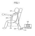
- FIG. 1 is a schematic representation of a seat belt system according to Embodiment 1 of the present invention.
- a motor driving apparatus 22 drives a motor 21 to wind up a seat belt 20.
- the operation for winding up the seat belt serves various functions.
- One function is to increase the constraint force in emergency mode in order to provide safety for the occupant 23.
- Another function is to provide automatic comfortable fitting when the seat belt is mounted to a buckle 25 in order to improve the comfort of the occupant 23.
- a further function is to provide automatic loading into a retractor 24 for the seat belt 20 in order to improve the aesthetic appearance of the vehicle.
- the motor driving apparatus 22 is energized from the vehicle's battery even when the ignition is off.
- the motor driving apparatus 22 suppresses the power consumption when it is not in operation if a power supply is being provided from the battery.
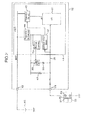
- the internal circuitry of the motor driving apparatus 22 is shown in FIG. 2 , the apparatus 22 being connected with a battery 10 and a buckle switch 33 in use.
- the apparatus 22 has a first connecting terminal 12 connected with the battery 10 and a second connecting terminal 13 connected with the buckle switch 33.
- the battery voltage is applied from the first connecting terminal 12.
- An input signal indicating a logic state of HIGH or LOW is applied from the second connecting terminal 13.
- a regulator 44 for backup and a current path 50 (see FIG. 3 ) that includes an analog switch or a transistor and a resistor 35 having a low resistance of 1 ⁇ to hundreds of ohms (e.g., 500 ⁇ ) to secure a predetermined amount of terminal current necessary for reliable operation of the switch.
- the path 50 is formed when current path shutoff means including the analog switch or the transistor is activated.
- a microcomputer ( ⁇ C) 31 is driven by a current supplied from the terminal 12 via a regulator 45 for ⁇ C.
- the microcomputer 31 goes to sleep while the buckle switch 33 is kept ON, the microcomputer 31 turns off an FET (field-effect transistor) 32 that is the transistor acting as the current path shutoff means controlled by a backup memory 30 which is recording and storing means operating when the microcomputer is asleep.
- the current flowing from the resistor 35 is shut off.
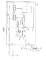
- the current 38 (see FIG. 3 ) flowing through the buckle switch 33 is maintained by a current path 51 ( FIG.
- the backup memory 30 is made of a CMOS logic device, little power is consumed in maintaining the control signal for the FET 32. Because a wakeup circuit 42 picking up a variation in the input signal 39 is also made of a CMOS logic device, almost no power consumption occurs.
- the wakeup circuit 42 forms a means for detecting switching of the input signal to the ASIC 41 and an informing means.
- the resistance of the resistor 40 is set to a necessary and sufficient level to suppress the dark current. Consequently, it is possible to prevent death of the vehicle's battery.
- the microcomputer 31 can recognize the logic LOW state of the input signal 39 and perform given processing. Where contrivances are made to record the state of the buckle switch prior to the sleeping state in the remaining region of the backup memory 30, if a wakeup operation should be performed erroneously, the microcomputer 31 can recognize the wakeup operation as erroneous and so the reliability of operation of the motor driving apparatus 22 can be enhanced.
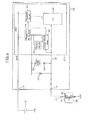
- the microcomputer 31 When the microcomputer goes to sleep while the buckle switch 33 is kept ON, the microcomputer 31 turns on the FET 32 that is controlled by the backup memory 30.
- the logic state of the input signal 39 to the ASIC 41 is pulled up by the combined resistance of the resistors 35 and 40 and kept at the logic HIGH state ( FIG. 4 ). If the buckle switch is allowed to stand for a long time under this condition, a thin oxide film 43 may be formed on the contacts 36 and 37 of the buckle switch 33 depending on conditions.
- the backup memory 30 is made of a CMOS logic device, almost no electric power is expended in holding the control signal for the FET 32. Also, the wakeup circuit 42 picking up variations in the input signal 39 is made of a CMOS logic device and, therefore, almost no power consumption occurs.
- the buckle switch 33 is ON, the resistor 35 permits flow of a large amount of current. In this case, the microcomputer is asleep while the switch 33 is kept OFF and so the power consumption of the motor driving apparatus 22 is suppressed to a low level.
- an electrical current 44 ( FIG. 5 ) flowing through the resistors 40 and 35 switches the logic state of the input signal 39 to the ASIC 41 from HIGH to LOW.
- the current 44 is used to destroy the oxide film formed on the internal contacts of the buckle switch.
- the wakeup circuit 42 in the ASIC 41 incorporating the microcomputer 31 picks up this change and wakes up the microcomputer. After the wakeup, the microcomputer 31 can recognize the logic HIGH state of the input signal 39 and perform given processing.
- the resistance value of the resistor 35 is so selected that the current value of the current 44 obtained at this time is high enough to destroy the thin oxide film 43 formed on the contacts 36 and 37 of the buckle switch 33. Consequently, the oxide film 43 is destroyed, so that the reliability of the operation of the buckle switch 33 can be maintained. Hence, a reliable wakeup operation can be performed.
- the microcomputer 31 Under normal operation (i.e., during wakeup), the microcomputer 31 preferably keeps ON the FET 32 controlled by the backup memory 30 because formation of the oxide film 43 on the contacts of the buckle switch 33 is prevented. Similarly, the initial value in the backup memory 30 may be so set as to turn on the FET 32. Consequently, if the power supply to the motor driving apparatus 22 should be momentarily cut off due to disconnection of a battery terminal and the memory 30 be cleared, the reliability of the operation of the buckle switch 33 is secured. Whenever the power supply is cut off instantaneously, the operation for waking up the microcomputer 31 is performed and, therefore, the possibility of battery death does not arise.
- FIG. 6 illustrates a sequence of control operations in Embodiment 1.
- the microcomputer 31 judges the state of the buckle switch 33 (S102). If the buckle switch 33 is ON, a decision is made as to whether or not there is an occupant (S103). If there is an occupant, a decision is made as to whether there is a danger of collision of the vehicle (S104). If there is no occupant, the motor is controlled to wind up the belt and the processing is terminated (S109). If the decision at S104 is YES (i.e., there is a danger of collision of the vehicle), the occupant is constrained emergently (S107).
- the occupant is constrained comfortably (S108). After the constraint, the motor is controlled to wind up the belt in either case, and the processing is terminated (S109). If the buckle switch 33 is OFF, a decision is made as to whether there is an occupant (S105). If there is no occupant, the seat belt is retracted and loaded (S106). If there is an occupant, the motor is controlled to wind up the belt, and the processing is terminated (S109). After the end of the operation for controlling the motor to wind up the belt, an operation for controlling the motor to wind up the belt is performed appropriately according to information about the buckle switch 33 and information offered by a vehicle communication.
- a factor causing the restoration from the sleeping condition is switching of the battery switch 33.
- Another factor is that a vehicle communication has been started.
- a further factor is that the battery is disconnected instantaneously.
- a still factor is that the brakes are applied emergently.
- the FET 32 can be replaced by an actively switchable device such as a PNP transistor.
- the backup memory 30 can be replaced by a storage device of low power consumption such as an EEPROM or flip-flop circuit.
- the advantages of the present invention can be applied to general switches having mechanically actuated open-close points (such as vehicle doors and windows), as well as to buckle switches.
- the motor driving apparatus 22 connected with the battery 10 and buckle switch 33 in use has the control unit 41, the FET 32 being the transistor capable of being kept ON or OFF by the backup memory 30 if the microcomputer is asleep, the resistor 35 connected in series with the FET 32, and the resistor 40 connected in parallel with the resistor 35, it being noted that the control unit 41 has the microcomputer 31 and the wakeup circuit 42 for waking up the microcomputer 31 when it is asleep according to the input signal whose logic state is switched by the state of the buckle switch 33.
- the resistor 35 connected in series with the FET 32 being capable of being kept ON or OFF by the power supply provided during sleeping and the resistor 40 whose resistance value is increased to prevent flow of excessive dark current if the buckle switch 33 is connected are disposed in parallel so that the current necessary for reliable operation of the buckle switch 33 can be secured.
- the microcomputer goes to sleep while the buckle switch is OFF, the state is maintained for a long time, and an oxide film is formed on the contacts of the buckle switch, then the oxide film is destroyed at the moment when the buckle switch is switched from OFF to ON. Because the current necessary for reliable operation of the buckle switch can be flowed through it, the wakeup can be performed normally.
- FIG. 7 shows the internal structure of a motor driving apparatus, 70, according to Embodiment 2.
- Embodiment 2 is similar in structure and control methods to Embodiment 1 except that a resistor 71 of low resistance value of about 1 ⁇ to hundreds of ohms (e.g., 500 ⁇ ), a resistor 72 of high resistance value of tens of kilohms or more (e.g., 1 M ⁇ ), and an FET 74 are incorporated within an ASIC 75 incorporating a microcomputer 31.
- the low-resistance resistor 71 in the ASIC supplies an electrical current when the buckle switch 33 is OFF.
- the high-resistance resistor 72 in the ASIC supplies an electrical current when the buckle switch 33 is ON.
- the FET 74 in the ASIC is controlled by the backup memory 30 and forms means for cutting off the current path.
- FIG. 8 shows the internal structure of a motor driving apparatus, 60, according to Embodiment 3.
- An ASIC 61 incorporating a microcomputer 31 has an input pin 62 withstanding high voltages. To make the withstand voltage of the input pin 62 higher than the battery voltage, an FET 63 for level shifting and the microcomputer 31 are connected via a buffer 65. An electrical current 66 for securing the reliability of operation of the buckle switch 33 is drawn from the battery voltage 67. The current 66 is used to destroy the oxide film formed on the internal contacts of the buckle switch. Consequently, high voltage resistance is imparted to the input pin 62 of the ASIC 61 having the microcomputer therein. Thus, it is easy to secure the current 66.
- the concepts for reducing the dark current and improving the reliability of operation of the buckle switch and control methods therefor are the same as for Embodiment 1.
- FIG. 9 shows the internal structure of a motor driving apparatus, 80, according to Embodiment 4.
- An electrical current 86 for securing the reliability of operation of the buckle switch 33 is drawn from the battery voltage 67 and holds the voltage across the buckle switch 33 at the battery voltage 67.
- the current 86 is used to destroy the oxide film formed on the internal contacts of the buckle switch.
- An FET 83 for level shifting is disposed to protect the low-current components inside an ASIC 81 incorporating a microcomputer against the battery voltage 67. This imparts high voltage resistance to the input pin 62 of the ASIC 81. It is easy to secure the current 86 and voltages necessary for reliable operation of the buckle switch 33.
- the concepts for reducing the dark current and improving the reliability of operation of the buckle switch and control methods therefor are the same as for Embodiment 1.
- FIG. 10 shows the internal structure of a motor driving apparatus, 90, according to Embodiment 5.
- an electrical current 96 for securing the reliability of operation of the buckle switch 33 is supplied from the terminal 12 via a diode, a resistor 91 and a transistor 93 used for current amplification.
- the value of the electrical current 96 flowing through the buckle switch 33 can be modified by varying the resistance value of the load resistor 91 for the transistor 93 for current amplification.
- the value of the current for securing the reliability of operation of the buckle switch differs according to the type of vehicle on which the motor driving apparatus is mounted. However, if the buckle switch 33 is changed and the value of the current 96 for securing the reliability of operation is changed, it is possible to cope with the variation simply by changing the value of the load resistor 91.
- the input pin 62 of the ASIC 61 incorporating the microcomputer is slightly pulled up towards the battery voltage by the use of a resistor 92 of high voltage of tens of kilohms or more (such as 1 M ⁇ ) as long as the specifications of the dark current permit, the dark current being allowed to flow through the motor driving apparatus 90 when the buckle switch 33 is ON. Consequently, when the FET 74 and the transistor 93 for current amplification are turned off for dark current reduction under control of the ASIC 61, if the buckle switch 33 is switched from ON to OFF, the resistor 92 permits the voltage on the input pin 62 of the ASIC 61 to rise quickly. This makes it possible to increase the operating speed when the consumption current of the motor driving apparatus 90 has been reduced.
- the ASIC 61 incorporating the microcomputer and used in Embodiments 2-4 can be utilized without modification.
- the concepts for reducing the dark current and for improving the reliability of operation of the buckle switch and control methods therefor are the same as for Embodiment 1. That is, the backup memory 30 holds the switching state of the FET 74 for controlling the path of the dark current and the switching state of the transistor 93 used for current amplification during the sleep of the ASIC 61 incorporating the microcomputer, and the wakeup circuit 42 detects the change of the state of the buckle switch 33 during the sleep of the ASIC 61.
Landscapes
- Engineering & Computer Science (AREA)
- Mechanical Engineering (AREA)
- Automotive Seat Belt Assembly (AREA)
Abstract
Description
- The present invention relates to a motor driving apparatus for a seat belt.
- One related art control unit mounted on a vehicle is designed to prevent battery death when the ignition is off and to reduce the dark current by bringing the control unit to standby when it is not in operation. Where the control unit is a motor driving apparatus for a seat belt and is designed to be put to sleep whether the buckle switch is ON or OFF, a technique for reducing the dark current flowing out of the buckle switch may be adopted as described in
JP-A-2008-238840 - In the related art, however, power supply for the circuit necessary to control the switch for switching the path is provided after wakeup and, therefore, if the buckle switch is switched while the microcomputer is asleep, the current necessary for reliable operation of the buckle switch cannot be supplied during the sleep. The related art is based on the concept that the path for the current necessary for reliable operation of the switch is secured by a circuit that operates when the microcomputer has woken up. Therefore, there is the problem that the buckle switch might not operate normally and thus the wakeup operation cannot be performed.
- It is an object of the present invention to provide a motor driving apparatus which is for use with a seat belt and which can perform a wakeup operation normally even if an oxide film is formed on the contacts of a buckle switch.
- Accordingly, the present invention provides a motor driving apparatus according to claim 1, which is connected with a battery and a buckle switch in use, the apparatus has a control unit including a microcomputer and a wakeup circuit for waking up the microcomputer when it is asleep according to an input signal whose logic state is switched by switching of the state of the buckle switch. The apparatus further includes a transistor capable of being kept ON or OFF by a backup memory even if the microcomputer is asleep, a first resistor connected in series with the transistor, and a second resistor connected in parallel with the first resistor.
- A further aspect of the invention relates to a motor driving apparatus connected with a battery and a buckle switch in use, said apparatus having a control unit comprising a microcomputer , a wakeup circuit for waking up the microcomputer while it is asleep according to an input signal whose logic state is switched by switching of the state of the buckle switch, a a transistor capable of being kept ON or OFF by a backup memory if the microcomputer is asleep a first resistor connected in series with the transistor and a second resistor connected in parallel with the first resistor.
- The present invention also provides a motor driving apparatus having a first connecting terminal connected with a battery, a second connecting terminal connected with a buckle switch, and a control unit incorporating a microcomputer. The control unit has a wakeup circuit for waking up the microcomputer when it is asleep according to an input signal whose logic state is switched based on a switching signal for switching the state of the buckle switch, the switching signal being entered from the second connecting terminal. The control unit further includes a transistor to which a battery voltage from the first connecting terminal is applied and which is capable of being kept ON or OFF by a backup memory even if the microcomputer is asleep, a first resistor connected in series with the transistor, and a second resistor connected in parallel with the first resistor. In the control unit, a transistor for level shifting and a buffer is connected between an input terminal to which the input signal is applied and the wakeup circuit. A second transistor for current amplification, a third resistor being a load resistor for the second transistor and connected in series with the second transistor, and a fourth resistor connected in parallel with the third resistor are connected between the input terminal of the control unit and the second connecting terminal.
- According to the invention, a seat belt motor driving apparatus can be offered which can perform a wakeup operation normally if an oxide film is formed on the contacts of the buckle switch.
- Other objects, features and advantages of the invention will become apparent from the following description of the embodiments of the invention taken in conjunction with the accompanying drawings.
-
-
FIG. 1 is a schematic representation of a seat belt system according to one embodiment of the present invention; -
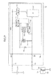
FIG. 2 is a circuit diagram, partially in block form, of a seat belt motor driving apparatus according to Embodiment 1 of the invention, showing the flows of electrical currents, and in which the buckle switch is closed; -
FIG. 3 is a circuit diagram similar toFIG. 2 , but in which the buckle switch is open; -
FIG. 4 is a circuit diagram similar toFIG. 3 , but in which the motor driving apparatus is asleep; -
FIG. 5 is a circuit diagram similar toFIG. 2 , but in which the motor driving apparatus is asleep; -
FIG. 6 is a flowchart illustrating control operations of the seat belt motor driving apparatus according to Embodiment 1; -
FIG. 7 is a circuit diagram showing the internal circuitry of a seat belt motor driving apparatus according to Embodiment 2; -
FIG. 8 is a circuit diagram showing the internal circuitry of a seat belt motor driving apparatus according to Embodiment 3; -
FIG. 9 is a circuit diagram showing the internal circuitry of a seat belt motor driving apparatus according to Embodiment 4; and -
FIG. 10 is a circuit diagram showing the internal circuitry of a seat belt motor driving apparatus according to Embodiment 5. - The preferred embodiments of the present invention are hereinafter described with reference to the accompanying drawings.
-
FIG. 1 is a schematic representation of a seat belt system according to Embodiment 1 of the present invention. - In the present system, a
motor driving apparatus 22 drives amotor 21 to wind up aseat belt 20. - The operation for winding up the seat belt serves various functions. One function is to increase the constraint force in emergency mode in order to provide safety for the
occupant 23. Another function is to provide automatic comfortable fitting when the seat belt is mounted to abuckle 25 in order to improve the comfort of theoccupant 23. A further function is to provide automatic loading into aretractor 24 for theseat belt 20 in order to improve the aesthetic appearance of the vehicle. - In the automatic comfortable fitting mode and automatic loading mode, the operation that would normally be performed when the ignition of the vehicle is off is required. Therefore, the
motor driving apparatus 22 is energized from the vehicle's battery even when the ignition is off. - To prevent death of the vehicle's battery, the
motor driving apparatus 22 suppresses the power consumption when it is not in operation if a power supply is being provided from the battery. - The internal circuitry of the
motor driving apparatus 22 according to the present embodiment is shown inFIG. 2 , theapparatus 22 being connected with abattery 10 and abuckle switch 33 in use. Theapparatus 22 has a first connectingterminal 12 connected with thebattery 10 and a second connectingterminal 13 connected with thebuckle switch 33. The battery voltage is applied from the first connectingterminal 12. An input signal indicating a logic state of HIGH or LOW is applied from the second connectingterminal 13. - When the state of the
buckle switch 33 is ON, an electrical current is allowed to flow from theterminal 12 via aregulator 44 for backup and a current path 50 (seeFIG. 3 ) that includes an analog switch or a transistor and aresistor 35 having a low resistance of 1 Ω to hundreds of ohms (e.g., 500 Ω) to secure a predetermined amount of terminal current necessary for reliable operation of the switch. Thepath 50 is formed when current path shutoff means including the analog switch or the transistor is activated. - A microcomputer (µC) 31 is driven by a current supplied from the
terminal 12 via aregulator 45 for µC. When themicrocomputer 31 goes to sleep while thebuckle switch 33 is kept ON, themicrocomputer 31 turns off an FET (field-effect transistor) 32 that is the transistor acting as the current path shutoff means controlled by abackup memory 30 which is recording and storing means operating when the microcomputer is asleep. As a result, the current flowing from theresistor 35 is shut off. However, the current 38 (seeFIG. 3 ) flowing through thebuckle switch 33 is maintained by a current path 51 (FIG. 3 ) which is formed when the current path shutoff means including the analog switch or transistors is deactivated and which passes through aresistor 40 having a high resistance (such as more than tens of kilohms (e.g., 1 MΩ)), because the high-resistance resistor 40 is connected. Under this condition, thecontacts buckle switch 33 are kept in contact with each other. Therefore, any oxide film which would impair the reliability of operation of thebuckle switch 33 is not formed. The logic state of theinput signal 39 to an ASIC (application-specific integrated circuit) 41 incorporating the microcomputer is kept LOW. - Since the
backup memory 30 is made of a CMOS logic device, little power is consumed in maintaining the control signal for theFET 32. Because awakeup circuit 42 picking up a variation in theinput signal 39 is also made of a CMOS logic device, almost no power consumption occurs. Thewakeup circuit 42 forms a means for detecting switching of the input signal to theASIC 41 and an informing means. The resistance of theresistor 40 is set to a necessary and sufficient level to suppress the dark current. Consequently, it is possible to prevent death of the vehicle's battery. - During sleep, if the
buckle switch 33 is switched from ON to OFF, the current 38 is cut off. The logic state of theinput signal 39 to theASIC 41 incorporating the microcomputer is switched to HIGH by the pull-up resistor 40 (FIG. 3 ). Thewakeup circuit 42 inside the ASIC 41 picks up this variation and wakes up themicrocomputer 31. After the wakeup, themicrocomputer 31 can recognize the logic LOW state of theinput signal 39 and perform given processing. Where contrivances are made to record the state of the buckle switch prior to the sleeping state in the remaining region of thebackup memory 30, if a wakeup operation should be performed erroneously, themicrocomputer 31 can recognize the wakeup operation as erroneous and so the reliability of operation of themotor driving apparatus 22 can be enhanced. - When the microcomputer goes to sleep while the
buckle switch 33 is kept ON, themicrocomputer 31 turns on theFET 32 that is controlled by thebackup memory 30. The logic state of theinput signal 39 to theASIC 41 is pulled up by the combined resistance of theresistors FIG. 4 ). If the buckle switch is allowed to stand for a long time under this condition, a thin oxide film 43 may be formed on thecontacts buckle switch 33 depending on conditions. - Since the
backup memory 30 is made of a CMOS logic device, almost no electric power is expended in holding the control signal for theFET 32. Also, thewakeup circuit 42 picking up variations in theinput signal 39 is made of a CMOS logic device and, therefore, almost no power consumption occurs. When thebuckle switch 33 is ON, theresistor 35 permits flow of a large amount of current. In this case, the microcomputer is asleep while theswitch 33 is kept OFF and so the power consumption of themotor driving apparatus 22 is suppressed to a low level. - During sleep, if the
buckle switch 33 is switched from OFF to ON, an electrical current 44 (FIG. 5 ) flowing through theresistors input signal 39 to theASIC 41 from HIGH to LOW. The current 44 is used to destroy the oxide film formed on the internal contacts of the buckle switch. Thewakeup circuit 42 in theASIC 41 incorporating themicrocomputer 31 picks up this change and wakes up the microcomputer. After the wakeup, themicrocomputer 31 can recognize the logic HIGH state of theinput signal 39 and perform given processing. - The resistance value of the
resistor 35 is so selected that the current value of the current 44 obtained at this time is high enough to destroy the thin oxide film 43 formed on thecontacts buckle switch 33. Consequently, the oxide film 43 is destroyed, so that the reliability of the operation of thebuckle switch 33 can be maintained. Hence, a reliable wakeup operation can be performed. - Under normal operation (i.e., during wakeup), the
microcomputer 31 preferably keeps ON theFET 32 controlled by thebackup memory 30 because formation of the oxide film 43 on the contacts of thebuckle switch 33 is prevented. Similarly, the initial value in thebackup memory 30 may be so set as to turn on theFET 32. Consequently, if the power supply to themotor driving apparatus 22 should be momentarily cut off due to disconnection of a battery terminal and thememory 30 be cleared, the reliability of the operation of thebuckle switch 33 is secured. Whenever the power supply is cut off instantaneously, the operation for waking up themicrocomputer 31 is performed and, therefore, the possibility of battery death does not arise. -
FIG. 6 illustrates a sequence of control operations in Embodiment 1. - In the present embodiment, if the battery is connected, a power supply is started to be provided without waiting for the ignition to be turned ON and the microcomputer is woken up (S101). After the wakeup, the
microcomputer 31 judges the state of the buckle switch 33 (S102). If thebuckle switch 33 is ON, a decision is made as to whether or not there is an occupant (S103). If there is an occupant, a decision is made as to whether there is a danger of collision of the vehicle (S104). If there is no occupant, the motor is controlled to wind up the belt and the processing is terminated (S109). If the decision at S104 is YES (i.e., there is a danger of collision of the vehicle), the occupant is constrained emergently (S107). If the decision is that there is no danger of collision of the vehicle, the occupant is constrained comfortably (S108). After the constraint, the motor is controlled to wind up the belt in either case, and the processing is terminated (S109). If thebuckle switch 33 is OFF, a decision is made as to whether there is an occupant (S105). If there is no occupant, the seat belt is retracted and loaded (S106). If there is an occupant, the motor is controlled to wind up the belt, and the processing is terminated (S109). After the end of the operation for controlling the motor to wind up the belt, an operation for controlling the motor to wind up the belt is performed appropriately according to information about thebuckle switch 33 and information offered by a vehicle communication. A decision is made as to whether or not the operation for controlling the motor to wind up the belt was done after a lapse of a given time since the fulfillment of the sleeping conditions (S 110). If the operation for controlling the motor to wind up the belt has not been done, the microcomputer is put to sleep to prevent battery death (S111). If the operation for controlling the motor to wind up the belt was done, control returns to the decision at step S102, where the state of thebuckle switch 33 is judged. - Then, a decision is made as to whether restoring from the sleeping condition is done (S112). A factor causing the restoration from the sleeping condition is switching of the
battery switch 33. Another factor is that a vehicle communication has been started. A further factor is that the battery is disconnected instantaneously. A still factor is that the brakes are applied emergently. - The
FET 32 can be replaced by an actively switchable device such as a PNP transistor. Furthermore, thebackup memory 30 can be replaced by a storage device of low power consumption such as an EEPROM or flip-flop circuit. - The advantages of the present invention can be applied to general switches having mechanically actuated open-close points (such as vehicle doors and windows), as well as to buckle switches.
- One feature of the present invention is that the
motor driving apparatus 22 connected with thebattery 10 andbuckle switch 33 in use has thecontrol unit 41, theFET 32 being the transistor capable of being kept ON or OFF by thebackup memory 30 if the microcomputer is asleep, theresistor 35 connected in series with theFET 32, and theresistor 40 connected in parallel with theresistor 35, it being noted that thecontrol unit 41 has themicrocomputer 31 and thewakeup circuit 42 for waking up themicrocomputer 31 when it is asleep according to the input signal whose logic state is switched by the state of thebuckle switch 33. In particular, if thebuckle switch 33 is switched while themicrocomputer 31 is asleep, theresistor 35 connected in series with theFET 32 being capable of being kept ON or OFF by the power supply provided during sleeping and theresistor 40 whose resistance value is increased to prevent flow of excessive dark current if thebuckle switch 33 is connected are disposed in parallel so that the current necessary for reliable operation of thebuckle switch 33 can be secured. - Because of this configuration, if the microcomputer goes to sleep while the buckle switch is OFF, the state is maintained for a long time, and an oxide film is formed on the contacts of the buckle switch, then the oxide film is destroyed at the moment when the buckle switch is switched from OFF to ON. Because the current necessary for reliable operation of the buckle switch can be flowed through it, the wakeup can be performed normally.
-
FIG. 7 shows the internal structure of a motor driving apparatus, 70, according to Embodiment 2. - Embodiment 2 is similar in structure and control methods to Embodiment 1 except that a
resistor 71 of low resistance value of about 1 Ω to hundreds of ohms (e.g., 500 Ω), aresistor 72 of high resistance value of tens of kilohms or more (e.g., 1 MΩ), and anFET 74 are incorporated within anASIC 75 incorporating amicrocomputer 31. The low-resistance resistor 71 in the ASIC supplies an electrical current when thebuckle switch 33 is OFF. The high-resistance resistor 72 in the ASIC supplies an electrical current when thebuckle switch 33 is ON. TheFET 74 in the ASIC is controlled by thebackup memory 30 and forms means for cutting off the current path. -
FIG. 8 shows the internal structure of a motor driving apparatus, 60, according to Embodiment 3. - An
ASIC 61 incorporating amicrocomputer 31 has aninput pin 62 withstanding high voltages. To make the withstand voltage of theinput pin 62 higher than the battery voltage, an FET 63 for level shifting and themicrocomputer 31 are connected via abuffer 65. An electrical current 66 for securing the reliability of operation of thebuckle switch 33 is drawn from thebattery voltage 67. The current 66 is used to destroy the oxide film formed on the internal contacts of the buckle switch. Consequently, high voltage resistance is imparted to theinput pin 62 of theASIC 61 having the microcomputer therein. Thus, it is easy to secure the current 66. The concepts for reducing the dark current and improving the reliability of operation of the buckle switch and control methods therefor are the same as for Embodiment 1. -
FIG. 9 shows the internal structure of a motor driving apparatus, 80, according to Embodiment 4. An electrical current 86 for securing the reliability of operation of thebuckle switch 33 is drawn from thebattery voltage 67 and holds the voltage across thebuckle switch 33 at thebattery voltage 67. The current 86 is used to destroy the oxide film formed on the internal contacts of the buckle switch. AnFET 83 for level shifting is disposed to protect the low-current components inside anASIC 81 incorporating a microcomputer against thebattery voltage 67. This imparts high voltage resistance to theinput pin 62 of theASIC 81. It is easy to secure the current 86 and voltages necessary for reliable operation of thebuckle switch 33. The concepts for reducing the dark current and improving the reliability of operation of the buckle switch and control methods therefor are the same as for Embodiment 1. -
FIG. 10 shows the internal structure of a motor driving apparatus, 90, according to Embodiment 5. - In the present embodiment, an electrical current 96 for securing the reliability of operation of the
buckle switch 33 is supplied from the terminal 12 via a diode, aresistor 91 and atransistor 93 used for current amplification. In the case of the present embodiment, the value of the electrical current 96 flowing through thebuckle switch 33 can be modified by varying the resistance value of theload resistor 91 for thetransistor 93 for current amplification. The value of the current for securing the reliability of operation of the buckle switch differs according to the type of vehicle on which the motor driving apparatus is mounted. However, if thebuckle switch 33 is changed and the value of the current 96 for securing the reliability of operation is changed, it is possible to cope with the variation simply by changing the value of theload resistor 91. - Furthermore, in the present embodiment, the
input pin 62 of theASIC 61 incorporating the microcomputer is slightly pulled up towards the battery voltage by the use of aresistor 92 of high voltage of tens of kilohms or more (such as 1 MΩ) as long as the specifications of the dark current permit, the dark current being allowed to flow through themotor driving apparatus 90 when thebuckle switch 33 is ON. Consequently, when theFET 74 and thetransistor 93 for current amplification are turned off for dark current reduction under control of theASIC 61, if thebuckle switch 33 is switched from ON to OFF, theresistor 92 permits the voltage on theinput pin 62 of theASIC 61 to rise quickly. This makes it possible to increase the operating speed when the consumption current of themotor driving apparatus 90 has been reduced. - In the present embodiment, the
ASIC 61 incorporating the microcomputer and used in Embodiments 2-4 can be utilized without modification. The concepts for reducing the dark current and for improving the reliability of operation of the buckle switch and control methods therefor are the same as for Embodiment 1. That is, thebackup memory 30 holds the switching state of theFET 74 for controlling the path of the dark current and the switching state of thetransistor 93 used for current amplification during the sleep of theASIC 61 incorporating the microcomputer, and thewakeup circuit 42 detects the change of the state of thebuckle switch 33 during the sleep of theASIC 61. - It should be further understood by those skilled in the art that although the foregoing description has been made on embodiments of the invention, the invention is not limited thereto and various changes and modifications may be made without departing from the spirit of the invention and the scope of the appended claims.
- The above embodiments of the invention as well as the appended claims and figures show multiple characterizing features of the invention in specific combinations. The skilled person will easily be able to consider further combinations or sub-combinations of these features in order to adapt the invention as defined in the in the claims to his specific needs.
Claims (7)
- A motor driving apparatus (22, 60, 90) connected with a battery (10) and a buckle switch (33) in use, said apparatus comprising:a control unit (41) including a microcomputer (31) and a wakeup circuit (42) for waking up the microcomputer when it is asleep according to an input signal (39) whose logic state is switched by switching of the state of the buckle switch (33);a transistor (32) capable of being kept ON or OFF by a backup memory (30) even if the microcomputer (31) is asleep;a first resistor (35) connected in series with the transistor (32); anda second resistor (40) connected in parallel with the first resistor (35).
- A motor driving apparatus (22, 60, 90) as set forth in claim 1, wherein the logic state of said input signal (39) is switched from LOW to HIGH when the buckle switch (33) is switched from ON to OFF while the microcomputer (31) is asleep, and wherein said wakeup circuit (42) detects switching of the input signal (39) and wakes up the microcomputer (31).
- A motor driving apparatus (22) as set forth in claim 1 or 2, wherein said microcomputer (31) turns on the transistor (32) when the microcomputer (31) is put to sleep while the buckle switch (33) is OFF.
- A motor driving apparatus (22) as set forth in one of claims 1 - 3, wherein the logic state of said input signal (39) is switched from HIGH to LOW when the buckle switch (33) is switched from OFF to ON while the microcomputer (31) is asleep, and wherein said wakeup circuit (42) detects switching of the input signal (39) and wakes up the microcomputer.
- A motor driving apparatus (60) as set forth in one of claims 1 - 4, wherein a battery voltage (67) is supplied to said transistor (74), and wherein said control unit (61) has a transistor (63) for level shifting and a buffer (65) between an input terminal (62) to which said input signal is applied and said wakeup circuit (42).
- A motor driving apparatus (90) as set forth in claim 5, wherein a second transistor (93) for current amplification, a third resistor (91) connected in series with the second transistor (93) and being a load resistor for the second transistor, and a fourth resistor (92) connected in parallel with the third resistor (91) are connected between said input terminal (62) of the control unit (61) and a connecting terminal (13) by which the buckle switch (33) is connected with the motor control unit (61).
- A motor driving apparatus (90) according to one of claims 1 - 6, further comprising:a first connecting terminal (12) connected with said battery (10); anda second connecting terminal (13) connected with said buckle switch (33);
wherein the switching signal is being entered from the second connecting terminal (13), wherein a battery voltage from the first connecting terminal (12) is applied to the transistor (74) andwherein said control unit (61) has a transistor (83) for level shifting and a buffer (65) between its input terminal (62) to which the input signal is applied and the wakeup circuit; andwherein a second transistor (93) for current amplification, a third resistor (91) being a load resistor for the second transistor (93) and connected in series with the second transistor (93), and a fourth resistor (92) connected in parallel with the third resistor (91) are connected between the input terminal (62) of the control unit (61) and the second connecting terminal (13).
Applications Claiming Priority (2)
| Application Number | Priority Date | Filing Date | Title |
|---|---|---|---|
| JP2009270964 | 2009-11-30 | ||
| JP2010101597A JP5352524B2 (en) | 2009-11-30 | 2010-04-27 | Motor drive device |
Publications (3)
| Publication Number | Publication Date |
|---|---|
| EP2327590A2 true EP2327590A2 (en) | 2011-06-01 |
| EP2327590A3 EP2327590A3 (en) | 2013-07-03 |
| EP2327590B1 EP2327590B1 (en) | 2016-08-17 |
Family
ID=43533466
Family Applications (1)
| Application Number | Title | Priority Date | Filing Date |
|---|---|---|---|
| EP10192454.6A Not-in-force EP2327590B1 (en) | 2009-11-30 | 2010-11-24 | Seat belt retractor motor driving apparatus |
Country Status (3)
| Country | Link |
|---|---|
| US (1) | US8350615B2 (en) |
| EP (1) | EP2327590B1 (en) |
| JP (1) | JP5352524B2 (en) |
Cited By (3)
| Publication number | Priority date | Publication date | Assignee | Title |
|---|---|---|---|---|
| EP2511143A1 (en) * | 2011-04-14 | 2012-10-17 | Autoliv Development AB | Control circuit for a mechanical locking device in a restraint system of a motor vehicle |
| CN103699199A (en) * | 2013-12-20 | 2014-04-02 | 青岛歌尔声学科技有限公司 | A power on/off control device for electronic equipment and an electronic equipment |
| EP3208158A4 (en) * | 2014-10-15 | 2018-06-20 | Kabushiki Kaisha Tokai-Rika-Denki-Seisakusho | Vehicle switch state detection device |
Families Citing this family (7)
| Publication number | Priority date | Publication date | Assignee | Title |
|---|---|---|---|---|
| JP5409750B2 (en) * | 2011-11-14 | 2014-02-05 | 本田技研工業株式会社 | Seat belt device |
| KR101315773B1 (en) * | 2012-05-03 | 2013-10-10 | 현대자동차주식회사 | Dark current cut off system and method for smart junction box of vehicle |
| JP6234127B2 (en) * | 2012-10-11 | 2017-11-22 | 株式会社Gsユアサ | Power storage device |
| KR101821327B1 (en) * | 2017-05-30 | 2018-01-24 | 콘티넨탈 오토모티브 게엠베하 | Input circuit capable of reducing dark current |
| KR102672245B1 (en) * | 2018-08-31 | 2024-06-03 | 주식회사 엘지에너지솔루션 | Apparatus for managing communication power source of battery pack |
| CN113012881A (en) * | 2021-03-01 | 2021-06-22 | 驭芯科技(上海)有限公司 | Method for assembling chip resistor on metal wire frame for mechanical switch type safety belt alarm sensor |
| CN113035479A (en) * | 2021-03-01 | 2021-06-25 | 驭芯科技(上海)有限公司 | Method for assembling chip resistor on metal wire frame and carrying out low-voltage packaging for mechanical switch type safety belt alarm sensor |
Citations (1)
| Publication number | Priority date | Publication date | Assignee | Title |
|---|---|---|---|---|
| JP2008238840A (en) | 2007-03-26 | 2008-10-09 | Hitachi Ltd | Seat belt control device |
Family Cites Families (8)
| Publication number | Priority date | Publication date | Assignee | Title |
|---|---|---|---|---|
| JPS58185350A (en) * | 1982-04-26 | 1983-10-29 | Nippon Soken Inc | Winding device of seat belt |
| US20030117018A1 (en) * | 2001-12-21 | 2003-06-26 | Young James M. | Current mirror seatbelt interface circuit |
| JP2006175896A (en) * | 2004-12-20 | 2006-07-06 | Tkj Kk | Passenger protecting device for vehicle |
| JP2006248285A (en) * | 2005-03-08 | 2006-09-21 | Takata Corp | Seat belt device |
| US7869921B2 (en) * | 2006-02-03 | 2011-01-11 | Tk Holdings Inc. | System and method for seat belt control |
| JP4916374B2 (en) * | 2007-04-24 | 2012-04-11 | 本田技研工業株式会社 | Vehicle seat belt device |
| DE102007029649A1 (en) * | 2007-06-26 | 2009-01-08 | Volkswagen Ag | Device for monitoring vehicle seating state, comprises seat belt buckle and seat belt strap, where belt guide is arranged at end of seat belt strap connected with vehicle mass by inserted belt guide |
| JP4892597B2 (en) * | 2009-09-28 | 2012-03-07 | 株式会社ホンダエレシス | Occupant detection system |
-
2010
- 2010-04-27 JP JP2010101597A patent/JP5352524B2/en not_active Expired - Fee Related
- 2010-11-23 US US12/952,501 patent/US8350615B2/en not_active Expired - Fee Related
- 2010-11-24 EP EP10192454.6A patent/EP2327590B1/en not_active Not-in-force
Patent Citations (1)
| Publication number | Priority date | Publication date | Assignee | Title |
|---|---|---|---|---|
| JP2008238840A (en) | 2007-03-26 | 2008-10-09 | Hitachi Ltd | Seat belt control device |
Cited By (4)
| Publication number | Priority date | Publication date | Assignee | Title |
|---|---|---|---|---|
| EP2511143A1 (en) * | 2011-04-14 | 2012-10-17 | Autoliv Development AB | Control circuit for a mechanical locking device in a restraint system of a motor vehicle |
| CN103699199A (en) * | 2013-12-20 | 2014-04-02 | 青岛歌尔声学科技有限公司 | A power on/off control device for electronic equipment and an electronic equipment |
| CN103699199B (en) * | 2013-12-20 | 2016-05-04 | 青岛歌尔声学科技有限公司 | A kind of control system of switching on or off electricity device of electronic equipment and a kind of electronic equipment |
| EP3208158A4 (en) * | 2014-10-15 | 2018-06-20 | Kabushiki Kaisha Tokai-Rika-Denki-Seisakusho | Vehicle switch state detection device |
Also Published As
| Publication number | Publication date |
|---|---|
| US20110128066A1 (en) | 2011-06-02 |
| US8350615B2 (en) | 2013-01-08 |
| EP2327590B1 (en) | 2016-08-17 |
| JP5352524B2 (en) | 2013-11-27 |
| EP2327590A3 (en) | 2013-07-03 |
| JP2011131873A (en) | 2011-07-07 |
Similar Documents
| Publication | Publication Date | Title |
|---|---|---|
| EP2327590B1 (en) | Seat belt retractor motor driving apparatus | |
| CN104808536B (en) | Vehicular electronic control unit | |
| JP4180597B2 (en) | Abnormality detection device for power supply circuit | |
| JP5408352B2 (en) | Power supply control circuit and power supply control device | |
| US7642674B2 (en) | Switch state assurance system | |
| CN100519278C (en) | Vehicle occupant protection system | |
| JP2011194902A (en) | Power feeding circuit | |
| EP0453255A1 (en) | Vehicle air bag apparatus | |
| US20050052081A1 (en) | Power circuit of a vehicular electronic control unit | |
| JP2013095238A (en) | Control device for vehicle | |
| JPH05501992A (en) | Method of operating a recording device powered by at least one rechargeable battery | |
| US5212836A (en) | Power source control circuitry for an automotive portable telephone | |
| JP2008265684A (en) | Vehicle seat belt device | |
| JP2012244658A (en) | On-board electronic control device | |
| KR101820293B1 (en) | Apparatus for managing power of vehicle and method for controlling the same | |
| KR102672245B1 (en) | Apparatus for managing communication power source of battery pack | |
| JPH10255955A (en) | Adjustment circuit depending on temperature of heating current of seat heating | |
| CN109661330B (en) | Vehicle power storage device | |
| US11646566B2 (en) | Apparatus for permanent supply with a switch | |
| WO2018219973A1 (en) | Input circuit capable of reducing dark current | |
| JP2005248988A (en) | Solenoid valve control device | |
| EP3098826B1 (en) | Switch monitoring circuit | |
| JP6171742B2 (en) | printer | |
| JP2012162139A (en) | Vehicle power source control device | |
| JP2005289204A (en) | Power supply control device |
Legal Events
| Date | Code | Title | Description |
|---|---|---|---|
| PUAI | Public reference made under article 153(3) epc to a published international application that has entered the european phase |
Free format text: ORIGINAL CODE: 0009012 |
|
| 17P | Request for examination filed |
Effective date: 20110316 |
|
| AK | Designated contracting states |
Kind code of ref document: A2 Designated state(s): AL AT BE BG CH CY CZ DE DK EE ES FI FR GB GR HR HU IE IS IT LI LT LU LV MC MK MT NL NO PL PT RO RS SE SI SK SM TR |
|
| AX | Request for extension of the european patent |
Extension state: BA ME |
|
| PUAL | Search report despatched |
Free format text: ORIGINAL CODE: 0009013 |
|
| AK | Designated contracting states |
Kind code of ref document: A3 Designated state(s): AL AT BE BG CH CY CZ DE DK EE ES FI FR GB GR HR HU IE IS IT LI LT LU LV MC MK MT NL NO PL PT RO RS SE SI SK SM TR |
|
| AX | Request for extension of the european patent |
Extension state: BA ME |
|
| RIC1 | Information provided on ipc code assigned before grant |
Ipc: B60R 16/03 20060101AFI20130527BHEP Ipc: B60R 22/34 20060101ALI20130527BHEP |
|
| REG | Reference to a national code |
Ref country code: DE Ref legal event code: R079 Ref document number: 602010035557 Country of ref document: DE Free format text: PREVIOUS MAIN CLASS: B60R0016030000 Ipc: B60R0022440000 |
|
| GRAP | Despatch of communication of intention to grant a patent |
Free format text: ORIGINAL CODE: EPIDOSNIGR1 |
|
| RIC1 | Information provided on ipc code assigned before grant |
Ipc: B60R 22/44 20060101AFI20160201BHEP |
|
| INTG | Intention to grant announced |
Effective date: 20160302 |
|
| GRAS | Grant fee paid |
Free format text: ORIGINAL CODE: EPIDOSNIGR3 |
|
| GRAA | (expected) grant |
Free format text: ORIGINAL CODE: 0009210 |
|
| AK | Designated contracting states |
Kind code of ref document: B1 Designated state(s): AL AT BE BG CH CY CZ DE DK EE ES FI FR GB GR HR HU IE IS IT LI LT LU LV MC MK MT NL NO PL PT RO RS SE SI SK SM TR |
|
| REG | Reference to a national code |
Ref country code: GB Ref legal event code: FG4D |
|
| RIN1 | Information on inventor provided before grant (corrected) |
Inventor name: SAITO, MASASHI Inventor name: NAGOSHI, HIROTO |
|
| REG | Reference to a national code |
Ref country code: CH Ref legal event code: EP |
|
| REG | Reference to a national code |
Ref country code: IE Ref legal event code: FG4D |
|
| REG | Reference to a national code |
Ref country code: AT Ref legal event code: REF Ref document number: 820723 Country of ref document: AT Kind code of ref document: T Effective date: 20160915 |
|
| REG | Reference to a national code |
Ref country code: DE Ref legal event code: R096 Ref document number: 602010035557 Country of ref document: DE |
|
| REG | Reference to a national code |
Ref country code: NL Ref legal event code: MP Effective date: 20160817 |
|
| REG | Reference to a national code |
Ref country code: LT Ref legal event code: MG4D |
|
| REG | Reference to a national code |
Ref country code: AT Ref legal event code: MK05 Ref document number: 820723 Country of ref document: AT Kind code of ref document: T Effective date: 20160817 |
|
| PG25 | Lapsed in a contracting state [announced via postgrant information from national office to epo] |
Ref country code: FI Free format text: LAPSE BECAUSE OF FAILURE TO SUBMIT A TRANSLATION OF THE DESCRIPTION OR TO PAY THE FEE WITHIN THE PRESCRIBED TIME-LIMIT Effective date: 20160817 Ref country code: IT Free format text: LAPSE BECAUSE OF FAILURE TO SUBMIT A TRANSLATION OF THE DESCRIPTION OR TO PAY THE FEE WITHIN THE PRESCRIBED TIME-LIMIT Effective date: 20160817 Ref country code: RS Free format text: LAPSE BECAUSE OF FAILURE TO SUBMIT A TRANSLATION OF THE DESCRIPTION OR TO PAY THE FEE WITHIN THE PRESCRIBED TIME-LIMIT Effective date: 20160817 Ref country code: NO Free format text: LAPSE BECAUSE OF FAILURE TO SUBMIT A TRANSLATION OF THE DESCRIPTION OR TO PAY THE FEE WITHIN THE PRESCRIBED TIME-LIMIT Effective date: 20161117 Ref country code: HR Free format text: LAPSE BECAUSE OF FAILURE TO SUBMIT A TRANSLATION OF THE DESCRIPTION OR TO PAY THE FEE WITHIN THE PRESCRIBED TIME-LIMIT Effective date: 20160817 Ref country code: LT Free format text: LAPSE BECAUSE OF FAILURE TO SUBMIT A TRANSLATION OF THE DESCRIPTION OR TO PAY THE FEE WITHIN THE PRESCRIBED TIME-LIMIT Effective date: 20160817 Ref country code: NL Free format text: LAPSE BECAUSE OF FAILURE TO SUBMIT A TRANSLATION OF THE DESCRIPTION OR TO PAY THE FEE WITHIN THE PRESCRIBED TIME-LIMIT Effective date: 20160817 |
|
| PG25 | Lapsed in a contracting state [announced via postgrant information from national office to epo] |
Ref country code: SE Free format text: LAPSE BECAUSE OF FAILURE TO SUBMIT A TRANSLATION OF THE DESCRIPTION OR TO PAY THE FEE WITHIN THE PRESCRIBED TIME-LIMIT Effective date: 20160817 Ref country code: AT Free format text: LAPSE BECAUSE OF FAILURE TO SUBMIT A TRANSLATION OF THE DESCRIPTION OR TO PAY THE FEE WITHIN THE PRESCRIBED TIME-LIMIT Effective date: 20160817 Ref country code: PL Free format text: LAPSE BECAUSE OF FAILURE TO SUBMIT A TRANSLATION OF THE DESCRIPTION OR TO PAY THE FEE WITHIN THE PRESCRIBED TIME-LIMIT Effective date: 20160817 Ref country code: LV Free format text: LAPSE BECAUSE OF FAILURE TO SUBMIT A TRANSLATION OF THE DESCRIPTION OR TO PAY THE FEE WITHIN THE PRESCRIBED TIME-LIMIT Effective date: 20160817 Ref country code: GR Free format text: LAPSE BECAUSE OF FAILURE TO SUBMIT A TRANSLATION OF THE DESCRIPTION OR TO PAY THE FEE WITHIN THE PRESCRIBED TIME-LIMIT Effective date: 20161118 Ref country code: ES Free format text: LAPSE BECAUSE OF FAILURE TO SUBMIT A TRANSLATION OF THE DESCRIPTION OR TO PAY THE FEE WITHIN THE PRESCRIBED TIME-LIMIT Effective date: 20160817 Ref country code: BE Free format text: LAPSE BECAUSE OF NON-PAYMENT OF DUE FEES Effective date: 20161130 Ref country code: PT Free format text: LAPSE BECAUSE OF FAILURE TO SUBMIT A TRANSLATION OF THE DESCRIPTION OR TO PAY THE FEE WITHIN THE PRESCRIBED TIME-LIMIT Effective date: 20161219 |
|
| PG25 | Lapsed in a contracting state [announced via postgrant information from national office to epo] |
Ref country code: EE Free format text: LAPSE BECAUSE OF FAILURE TO SUBMIT A TRANSLATION OF THE DESCRIPTION OR TO PAY THE FEE WITHIN THE PRESCRIBED TIME-LIMIT Effective date: 20160817 Ref country code: RO Free format text: LAPSE BECAUSE OF FAILURE TO SUBMIT A TRANSLATION OF THE DESCRIPTION OR TO PAY THE FEE WITHIN THE PRESCRIBED TIME-LIMIT Effective date: 20160817 |
|
| REG | Reference to a national code |
Ref country code: DE Ref legal event code: R097 Ref document number: 602010035557 Country of ref document: DE |
|
| PG25 | Lapsed in a contracting state [announced via postgrant information from national office to epo] |
Ref country code: CZ Free format text: LAPSE BECAUSE OF FAILURE TO SUBMIT A TRANSLATION OF THE DESCRIPTION OR TO PAY THE FEE WITHIN THE PRESCRIBED TIME-LIMIT Effective date: 20160817 Ref country code: BE Free format text: LAPSE BECAUSE OF FAILURE TO SUBMIT A TRANSLATION OF THE DESCRIPTION OR TO PAY THE FEE WITHIN THE PRESCRIBED TIME-LIMIT Effective date: 20160817 Ref country code: DK Free format text: LAPSE BECAUSE OF FAILURE TO SUBMIT A TRANSLATION OF THE DESCRIPTION OR TO PAY THE FEE WITHIN THE PRESCRIBED TIME-LIMIT Effective date: 20160817 Ref country code: SK Free format text: LAPSE BECAUSE OF FAILURE TO SUBMIT A TRANSLATION OF THE DESCRIPTION OR TO PAY THE FEE WITHIN THE PRESCRIBED TIME-LIMIT Effective date: 20160817 Ref country code: SM Free format text: LAPSE BECAUSE OF FAILURE TO SUBMIT A TRANSLATION OF THE DESCRIPTION OR TO PAY THE FEE WITHIN THE PRESCRIBED TIME-LIMIT Effective date: 20160817 Ref country code: BG Free format text: LAPSE BECAUSE OF FAILURE TO SUBMIT A TRANSLATION OF THE DESCRIPTION OR TO PAY THE FEE WITHIN THE PRESCRIBED TIME-LIMIT Effective date: 20161117 |
|
| PLBE | No opposition filed within time limit |
Free format text: ORIGINAL CODE: 0009261 |
|
| STAA | Information on the status of an ep patent application or granted ep patent |
Free format text: STATUS: NO OPPOSITION FILED WITHIN TIME LIMIT |
|
| REG | Reference to a national code |
Ref country code: CH Ref legal event code: PL |
|
| 26N | No opposition filed |
Effective date: 20170518 |
|
| GBPC | Gb: european patent ceased through non-payment of renewal fee |
Effective date: 20161124 |
|
| PG25 | Lapsed in a contracting state [announced via postgrant information from national office to epo] |
Ref country code: CH Free format text: LAPSE BECAUSE OF NON-PAYMENT OF DUE FEES Effective date: 20161130 Ref country code: LI Free format text: LAPSE BECAUSE OF NON-PAYMENT OF DUE FEES Effective date: 20161130 |
|
| REG | Reference to a national code |
Ref country code: IE Ref legal event code: MM4A |
|
| REG | Reference to a national code |
Ref country code: FR Ref legal event code: ST Effective date: 20170731 |
|
| PG25 | Lapsed in a contracting state [announced via postgrant information from national office to epo] |
Ref country code: SI Free format text: LAPSE BECAUSE OF FAILURE TO SUBMIT A TRANSLATION OF THE DESCRIPTION OR TO PAY THE FEE WITHIN THE PRESCRIBED TIME-LIMIT Effective date: 20160817 |
|
| PG25 | Lapsed in a contracting state [announced via postgrant information from national office to epo] |
Ref country code: LU Free format text: LAPSE BECAUSE OF NON-PAYMENT OF DUE FEES Effective date: 20161130 |
|
| PG25 | Lapsed in a contracting state [announced via postgrant information from national office to epo] |
Ref country code: FR Free format text: LAPSE BECAUSE OF NON-PAYMENT OF DUE FEES Effective date: 20161130 |
|
| PG25 | Lapsed in a contracting state [announced via postgrant information from national office to epo] |
Ref country code: GB Free format text: LAPSE BECAUSE OF NON-PAYMENT OF DUE FEES Effective date: 20161124 Ref country code: IE Free format text: LAPSE BECAUSE OF NON-PAYMENT OF DUE FEES Effective date: 20161124 |
|
| PG25 | Lapsed in a contracting state [announced via postgrant information from national office to epo] |
Ref country code: CY Free format text: LAPSE BECAUSE OF FAILURE TO SUBMIT A TRANSLATION OF THE DESCRIPTION OR TO PAY THE FEE WITHIN THE PRESCRIBED TIME-LIMIT Effective date: 20160817 Ref country code: HU Free format text: LAPSE BECAUSE OF FAILURE TO SUBMIT A TRANSLATION OF THE DESCRIPTION OR TO PAY THE FEE WITHIN THE PRESCRIBED TIME-LIMIT; INVALID AB INITIO Effective date: 20101124 |
|
| PG25 | Lapsed in a contracting state [announced via postgrant information from national office to epo] |
Ref country code: IS Free format text: LAPSE BECAUSE OF FAILURE TO SUBMIT A TRANSLATION OF THE DESCRIPTION OR TO PAY THE FEE WITHIN THE PRESCRIBED TIME-LIMIT Effective date: 20160817 Ref country code: MK Free format text: LAPSE BECAUSE OF FAILURE TO SUBMIT A TRANSLATION OF THE DESCRIPTION OR TO PAY THE FEE WITHIN THE PRESCRIBED TIME-LIMIT Effective date: 20160817 Ref country code: TR Free format text: LAPSE BECAUSE OF FAILURE TO SUBMIT A TRANSLATION OF THE DESCRIPTION OR TO PAY THE FEE WITHIN THE PRESCRIBED TIME-LIMIT Effective date: 20160817 Ref country code: MC Free format text: LAPSE BECAUSE OF FAILURE TO SUBMIT A TRANSLATION OF THE DESCRIPTION OR TO PAY THE FEE WITHIN THE PRESCRIBED TIME-LIMIT Effective date: 20160817 |
|
| PG25 | Lapsed in a contracting state [announced via postgrant information from national office to epo] |
Ref country code: MT Free format text: LAPSE BECAUSE OF NON-PAYMENT OF DUE FEES Effective date: 20161124 |
|
| PG25 | Lapsed in a contracting state [announced via postgrant information from national office to epo] |
Ref country code: AL Free format text: LAPSE BECAUSE OF FAILURE TO SUBMIT A TRANSLATION OF THE DESCRIPTION OR TO PAY THE FEE WITHIN THE PRESCRIBED TIME-LIMIT Effective date: 20160817 |
|
| REG | Reference to a national code |
Ref country code: DE Ref legal event code: R084 Ref document number: 602010035557 Country of ref document: DE |
|
| PGFP | Annual fee paid to national office [announced via postgrant information from national office to epo] |
Ref country code: DE Payment date: 20201110 Year of fee payment: 11 |
|
| REG | Reference to a national code |
Ref country code: DE Ref legal event code: R119 Ref document number: 602010035557 Country of ref document: DE |
|
| PG25 | Lapsed in a contracting state [announced via postgrant information from national office to epo] |
Ref country code: DE Free format text: LAPSE BECAUSE OF NON-PAYMENT OF DUE FEES Effective date: 20220601 |