EP2327580A1 - Controlling vapor emission in a small engine fuel tank system - Google Patents
Controlling vapor emission in a small engine fuel tank system Download PDFInfo
- Publication number
- EP2327580A1 EP2327580A1 EP10190042A EP10190042A EP2327580A1 EP 2327580 A1 EP2327580 A1 EP 2327580A1 EP 10190042 A EP10190042 A EP 10190042A EP 10190042 A EP10190042 A EP 10190042A EP 2327580 A1 EP2327580 A1 EP 2327580A1
- Authority
- EP
- European Patent Office
- Prior art keywords
- tank
- vapor
- valve
- fuel
- vent
- Prior art date
- Legal status (The legal status is an assumption and is not a legal conclusion. Google has not performed a legal analysis and makes no representation as to the accuracy of the status listed.)
- Withdrawn
Links
- 239000002828 fuel tank Substances 0.000 title claims description 15
- 239000000446 fuel Substances 0.000 claims abstract description 35
- 239000000945 filler Substances 0.000 claims abstract description 21
- 239000007788 liquid Substances 0.000 claims description 4
- 230000000007 visual effect Effects 0.000 claims description 3
- 230000000630 rising effect Effects 0.000 claims 1
- 238000004519 manufacturing process Methods 0.000 abstract 1
- 230000011664 signaling Effects 0.000 abstract 1
- 238000004891 communication Methods 0.000 description 1
- 238000001816 cooling Methods 0.000 description 1
- 238000000034 method Methods 0.000 description 1
- 238000012986 modification Methods 0.000 description 1
- 230000004048 modification Effects 0.000 description 1
- 238000007789 sealing Methods 0.000 description 1
Images

Classifications
-
- B—PERFORMING OPERATIONS; TRANSPORTING
- B60—VEHICLES IN GENERAL
- B60K—ARRANGEMENT OR MOUNTING OF PROPULSION UNITS OR OF TRANSMISSIONS IN VEHICLES; ARRANGEMENT OR MOUNTING OF PLURAL DIVERSE PRIME-MOVERS IN VEHICLES; AUXILIARY DRIVES FOR VEHICLES; INSTRUMENTATION OR DASHBOARDS FOR VEHICLES; ARRANGEMENTS IN CONNECTION WITH COOLING, AIR INTAKE, GAS EXHAUST OR FUEL SUPPLY OF PROPULSION UNITS IN VEHICLES
- B60K15/00—Arrangement in connection with fuel supply of combustion engines or other fuel consuming energy converters, e.g. fuel cells; Mounting or construction of fuel tanks
- B60K15/03—Fuel tanks
- B60K15/035—Fuel tanks characterised by venting means
-
- B—PERFORMING OPERATIONS; TRANSPORTING
- B60—VEHICLES IN GENERAL
- B60K—ARRANGEMENT OR MOUNTING OF PROPULSION UNITS OR OF TRANSMISSIONS IN VEHICLES; ARRANGEMENT OR MOUNTING OF PLURAL DIVERSE PRIME-MOVERS IN VEHICLES; AUXILIARY DRIVES FOR VEHICLES; INSTRUMENTATION OR DASHBOARDS FOR VEHICLES; ARRANGEMENTS IN CONNECTION WITH COOLING, AIR INTAKE, GAS EXHAUST OR FUEL SUPPLY OF PROPULSION UNITS IN VEHICLES
- B60K15/00—Arrangement in connection with fuel supply of combustion engines or other fuel consuming energy converters, e.g. fuel cells; Mounting or construction of fuel tanks
- B60K15/03—Fuel tanks
- B60K15/035—Fuel tanks characterised by venting means
- B60K15/03519—Valve arrangements in the vent line
-
- B—PERFORMING OPERATIONS; TRANSPORTING
- B60—VEHICLES IN GENERAL
- B60K—ARRANGEMENT OR MOUNTING OF PROPULSION UNITS OR OF TRANSMISSIONS IN VEHICLES; ARRANGEMENT OR MOUNTING OF PLURAL DIVERSE PRIME-MOVERS IN VEHICLES; AUXILIARY DRIVES FOR VEHICLES; INSTRUMENTATION OR DASHBOARDS FOR VEHICLES; ARRANGEMENTS IN CONNECTION WITH COOLING, AIR INTAKE, GAS EXHAUST OR FUEL SUPPLY OF PROPULSION UNITS IN VEHICLES
- B60K15/00—Arrangement in connection with fuel supply of combustion engines or other fuel consuming energy converters, e.g. fuel cells; Mounting or construction of fuel tanks
- B60K15/03—Fuel tanks
- B60K15/035—Fuel tanks characterised by venting means
- B60K15/03504—Fuel tanks characterised by venting means adapted to avoid loss of fuel or fuel vapour, e.g. with vapour recovery systems
-
- B—PERFORMING OPERATIONS; TRANSPORTING
- B60—VEHICLES IN GENERAL
- B60K—ARRANGEMENT OR MOUNTING OF PROPULSION UNITS OR OF TRANSMISSIONS IN VEHICLES; ARRANGEMENT OR MOUNTING OF PLURAL DIVERSE PRIME-MOVERS IN VEHICLES; AUXILIARY DRIVES FOR VEHICLES; INSTRUMENTATION OR DASHBOARDS FOR VEHICLES; ARRANGEMENTS IN CONNECTION WITH COOLING, AIR INTAKE, GAS EXHAUST OR FUEL SUPPLY OF PROPULSION UNITS IN VEHICLES
- B60K15/00—Arrangement in connection with fuel supply of combustion engines or other fuel consuming energy converters, e.g. fuel cells; Mounting or construction of fuel tanks
- B60K15/03—Fuel tanks
- B60K15/04—Tank inlets
-
- B—PERFORMING OPERATIONS; TRANSPORTING
- B60—VEHICLES IN GENERAL
- B60K—ARRANGEMENT OR MOUNTING OF PROPULSION UNITS OR OF TRANSMISSIONS IN VEHICLES; ARRANGEMENT OR MOUNTING OF PLURAL DIVERSE PRIME-MOVERS IN VEHICLES; AUXILIARY DRIVES FOR VEHICLES; INSTRUMENTATION OR DASHBOARDS FOR VEHICLES; ARRANGEMENTS IN CONNECTION WITH COOLING, AIR INTAKE, GAS EXHAUST OR FUEL SUPPLY OF PROPULSION UNITS IN VEHICLES
- B60K15/00—Arrangement in connection with fuel supply of combustion engines or other fuel consuming energy converters, e.g. fuel cells; Mounting or construction of fuel tanks
- B60K15/03—Fuel tanks
- B60K15/035—Fuel tanks characterised by venting means
- B60K2015/03561—Venting means working at specific times
- B60K2015/03576—Venting during filling the reservoir
-
- B—PERFORMING OPERATIONS; TRANSPORTING
- B60—VEHICLES IN GENERAL
- B60Y—INDEXING SCHEME RELATING TO ASPECTS CROSS-CUTTING VEHICLE TECHNOLOGY
- B60Y2200/00—Type of vehicle
- B60Y2200/20—Off-Road Vehicles
- B60Y2200/22—Agricultural vehicles
- B60Y2200/223—Ridable lawn mowers
Definitions
- the present invention relates to fuel tank systems for small engines of the type employed for portable appliances such as portable power generating sets, garden tractors, lawn mowers and other such devices where the fuel tank is either mounted on the engine or closely adjacent thereto.
- Fuel tanks of this type are typically refueled by removing the filler cap and pouring fuel from a container having a pouring spout, or by pouring from a container and using a funnel.
- the filler cap In order to meet the requirement that a fuel tank for a small engine not emit fuel vapor, the filler cap must be sealed to prevent fuel vapor emission. If the filler cap is sealed then other provisions must be made for admitting make up air to the tank during engine operation. Furthermore, provisions must be made for overpressure relief. Thus, it has been desired to find a way or means of sealing a small engine fuel tank, yet provide for make-up air and over pressure relief and to do so in a cost-effective manner without requiring redesign or retooling of the tanks.
- U.S. Patent No. 5,666,989 discloses a fuel vapor control system for automotive applications, comprising a fuel tank; a vapor vent valve arranged to vent excess fuel vapor from the tank to a vent outlet and to close the vent outlet when the fuel level reaches a predetermined level in the tank; a filler neck which extends obliquely to the side wall of the tank and joins the side wall with its inner end, wherein the inner end of the filler neck is disposed flush with the side wall at a level below the top wall of the tank; and a normally closed valve (42) disposed to block vapor flow in said vent outlet and operable to open at a predetermined positive vapor pressure in the tank.
- the fuel When the liquid fuel level within the tank reaches the inner end of the filler neck, the fuel then rises up the filler neck to provide an indication to either the operator or an automatic shutoff on the fuel-dispensing nozzle to shut off the input of fuel into filler neck, while creating an expansion volume in the upper portion of the fuel tank.
- the present invention provides a fuel vapor emission control valve in the tank which controls the flow of fuel vapor through a passage extending exteriorly of the tank and also includes a rollover or upset valve preventing liquid fuel from escaping the tank.
- the vapor vent valve includes a head valve which retains the vapor in the tank until a predetermined positive pressure is reached; and, the vent valve also includes a reverse flow check valve permitting make-up air to enter the tank as fuel is withdrawn or upon a sub-atmospheric pressure occurring in the tank such as, for example, by cooling of the tank.
- the fuel vapor vent passage may be connected externally to either a vapor storage device or the air inlet of the engine.
- the invention includes fitting an existing fuel tank with a filler tube extending to a predetermined level or depth in the tank to cause the fuel to rise rapidly in the filler tube upon reaching the lower end of the tube during refueling to signal the operator that tank has reached the desired fill level.
- This arrangement prevents overfilling and preserves a vapor dome in the tank above the liquid level of the fuel to ensure proper functioning of the vapor vent valve.
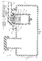
- FIG. 1 is a pictorial schematic showing a small engine fuel tank in cross-section with the filler tube and vapor vent valve of the present invention installed thereon; and, the connections to either a vapor storage device or alternatively the engine air inlet are shown in dashed line;
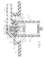
- FIG. 2 is an enlarged detail of the vapor vent valve of FIG. 1 ;
- FIG. 3 is an enlarged view of a portion of FIG. 2 with the vapor vent valve closed;
- FIG. 4 is a view similar to FIG. 3 showing the vapor vent valve opened.
- FIG. 5 is a view similar to FIG. 3 with the reverse flow valve shown open in response to a vacuum in the tank.
- the small engine fuel tank assembly of the present invention is indicated generally at 10 and includes an existing tank wall structure 12 with a new filler tube 14 having a vapor tight removable closure 16 received on the exterior end of the tube with the lower end of the tube 14 extending into the tank to a desired depth or level indicated by the reference character d.
- a separate access opening 18 is formed in the upper portion of the tank wall and through which is inserted a combination rollover and vapor vent valve indicated generally at 20 which has a lower housing portion 22 extending into the tank and an upper housing portion 24 with an outwardly extending flange 26 thereabout attached to the tank wall and sealed thereabout by any suitable expedient as, for example, weldment.
- the lower valve housing 22 has a float 28 disposed therein with a flexible valve member 30 disposed on the upper end of the float which closes in the event that fuel rises above the level d due to sloshing, overfilling or the tank becoming severely tipped or inverted, under which conditions valve member 30 seats upon a valve seat 32 formed in the upper housing 24.
- valve seat 32 is formed on the lower end of a vent passage 34 which communicates with an enlarged diameter upper portion 36 which communicates with vent passage 38 which extends outwardly through attachment fitting 40 which may be formed as part of the upper housing 24.
- the enlarged diameter portion 36 of the vent passage has slidably received therein a valve member 42 which has a passage 44 therethrough and which has the lower surface 46 thereof configured to seat upon surface 48 formed in the upper body at the upper end of passage 34.
- Valve member 42 has formed therein a valving chamber 50 with a valve seat 52 formed in an inverted position therein on the lower end of the flow passage 54 which communicates with vent passage 38.
- Chamber 50 has received therein a check valve member 56 which may be in the form of a relatively light weight ball which may be formed of plastic and which seats on valve set 52 and closes passage 54 when a positive pressure exists in the fuel tank.
- the enlarged diameter 36, in which valve member 42 slides has slots or passages 60 formed therein to permit passage of vapors for communication with passage 38 when the valve member 42 is in the upward position and not seated on the seating surface 48.
- valve member 42 If the vapor pressure in the tank is substantially atmospheric or only slightly above, the valve member 42 is seated on seating surface 48 and only a small amount of vapor can enter the valving chamber 50 and the flow therethrough passage 44 causes ball valve 56 to seat against the seating surface 52 as shown in FIG. 3 preventing escape of vapor. As the vapor pressure increases, valve member 42 is moved upwardly to the position as shown in FIG. 4 permitting passage of vapor through passages 60 into the passage 38; and, as shown in FIG. 1 , to either a storage device 70 or to the engine air inlet 72.
- the present invention thus provides a simple, relatively low cost and easy to install technique for modifying an existing small engine fuel tank for control of fuel vapor emissions to meet current requirements.
- the invention combines a filler tube extending in the tank to maintain a vapor dome with a vapor vent control/rollover valve to prevent fuel vapor from escaping to the atmosphere upon connection to either a storage device or the engine air inlet.
Landscapes
- Engineering & Computer Science (AREA)
- Life Sciences & Earth Sciences (AREA)
- Sustainable Development (AREA)
- Sustainable Energy (AREA)
- Chemical & Material Sciences (AREA)
- Combustion & Propulsion (AREA)
- Transportation (AREA)
- Mechanical Engineering (AREA)
- Cooling, Air Intake And Gas Exhaust, And Fuel Tank Arrangements In Propulsion Units (AREA)
- Supplying Secondary Fuel Or The Like To Fuel, Air Or Fuel-Air Mixtures (AREA)
Abstract
Description
- The present invention relates to fuel tank systems for small engines of the type employed for portable appliances such as portable power generating sets, garden tractors, lawn mowers and other such devices where the fuel tank is either mounted on the engine or closely adjacent thereto. Fuel tanks of this type are typically refueled by removing the filler cap and pouring fuel from a container having a pouring spout, or by pouring from a container and using a funnel.
- Small engine fuel systems have recently been subjected to mandated requirements for fuel vapor emission control and it has been required to prevent vapor emission from the tank during operation and when the engine is not operating.
- Heretofore small engine fuel systems have often employed a tank having an open vent in the filler cap for providing make-up air in the tank as fuel was withdrawn but which permitted escape of fuel vapor to the atmosphere.
- In order to meet the requirement that a fuel tank for a small engine not emit fuel vapor, the filler cap must be sealed to prevent fuel vapor emission. If the filler cap is sealed then other provisions must be made for admitting make up air to the tank during engine operation. Furthermore, provisions must be made for overpressure relief. Thus, it has been desired to find a way or means of sealing a small engine fuel tank, yet provide for make-up air and over pressure relief and to do so in a cost-effective manner without requiring redesign or retooling of the tanks.
-
U.S. Patent No. 5,666,989 discloses a fuel vapor control system for automotive applications, comprising a fuel tank; a vapor vent valve arranged to vent excess fuel vapor from the tank to a vent outlet and to close the vent outlet when the fuel level reaches a predetermined level in the tank; a filler neck which extends obliquely to the side wall of the tank and joins the side wall with its inner end, wherein the inner end of the filler neck is disposed flush with the side wall at a level below the top wall of the tank; and a normally closed valve (42) disposed to block vapor flow in said vent outlet and operable to open at a predetermined positive vapor pressure in the tank. When the liquid fuel level within the tank reaches the inner end of the filler neck, the fuel then rises up the filler neck to provide an indication to either the operator or an automatic shutoff on the fuel-dispensing nozzle to shut off the input of fuel into filler neck, while creating an expansion volume in the upper portion of the fuel tank. - The present invention, as is defined in independent claim 1, provides a fuel vapor emission control valve in the tank which controls the flow of fuel vapor through a passage extending exteriorly of the tank and also includes a rollover or upset valve preventing liquid fuel from escaping the tank. The vapor vent valve includes a head valve which retains the vapor in the tank until a predetermined positive pressure is reached; and, the vent valve also includes a reverse flow check valve permitting make-up air to enter the tank as fuel is withdrawn or upon a sub-atmospheric pressure occurring in the tank such as, for example, by cooling of the tank. The fuel vapor vent passage may be connected externally to either a vapor storage device or the air inlet of the engine. The invention includes fitting an existing fuel tank with a filler tube extending to a predetermined level or depth in the tank to cause the fuel to rise rapidly in the filler tube upon reaching the lower end of the tube during refueling to signal the operator that tank has reached the desired fill level. This arrangement prevents overfilling and preserves a vapor dome in the tank above the liquid level of the fuel to ensure proper functioning of the vapor vent valve.
-
FIG. 1 is a pictorial schematic showing a small engine fuel tank in cross-section with the filler tube and vapor vent valve of the present invention installed thereon; and, the connections to either a vapor storage device or alternatively the engine air inlet are shown in dashed line; -
FIG. 2 is an enlarged detail of the vapor vent valve ofFIG. 1 ; -
FIG. 3 is an enlarged view of a portion ofFIG. 2 with the vapor vent valve closed; -
FIG. 4 is a view similar toFIG. 3 showing the vapor vent valve opened; and, -
FIG. 5 is a view similar toFIG. 3 with the reverse flow valve shown open in response to a vacuum in the tank. - Referring to
FIGS. 1 and2 , the small engine fuel tank assembly of the present invention is indicated generally at 10 and includes an existingtank wall structure 12 with anew filler tube 14 having a vapor tightremovable closure 16 received on the exterior end of the tube with the lower end of thetube 14 extending into the tank to a desired depth or level indicated by the reference character d. - A
separate access opening 18 is formed in the upper portion of the tank wall and through which is inserted a combination rollover and vapor vent valve indicated generally at 20 which has alower housing portion 22 extending into the tank and anupper housing portion 24 with an outwardly extendingflange 26 thereabout attached to the tank wall and sealed thereabout by any suitable expedient as, for example, weldment. - The
lower valve housing 22 has afloat 28 disposed therein with aflexible valve member 30 disposed on the upper end of the float which closes in the event that fuel rises above the level d due to sloshing, overfilling or the tank becoming severely tipped or inverted, under whichconditions valve member 30 seats upon avalve seat 32 formed in theupper housing 24. - The
valve seat 32 is formed on the lower end of avent passage 34 which communicates with an enlarged diameterupper portion 36 which communicates withvent passage 38 which extends outwardly through attachment fitting 40 which may be formed as part of theupper housing 24. - The enlarged
diameter portion 36 of the vent passage has slidably received therein avalve member 42 which has apassage 44 therethrough and which has thelower surface 46 thereof configured to seat uponsurface 48 formed in the upper body at the upper end ofpassage 34. When thevalve member 42 is in the lower position shown inFIG. 3 and FIG. 5 , flow throughpassage 34 must transit throughpassage 44, not the enlargeddiameter passage 36. - Valve
member 42 has formed therein avalving chamber 50 with avalve seat 52 formed in an inverted position therein on the lower end of theflow passage 54 which communicates withvent passage 38.Chamber 50 has received therein acheck valve member 56 which may be in the form of a relatively light weight ball which may be formed of plastic and which seats on valve set 52 and closespassage 54 when a positive pressure exists in the fuel tank. - With reference to
FIGS. 3, 4 and 5 , it will be seen that the enlargeddiameter 36, in whichvalve member 42 slides, has slots orpassages 60 formed therein to permit passage of vapors for communication withpassage 38 when thevalve member 42 is in the upward position and not seated on theseating surface 48. - In operation, with the
filler cap 16 removed and the tank refueled throughfiller tube 14, when the level of the fuel reaches the height d, with continued filling a fuel level increases rapidly in thetube 14 giving visual notice to the operator that the tank has reached the desired fill level. After refueling when the filler cap is replaced, the tank is sealed except forvent passage 38 so long as the tank is in the upright position or is not substantially tilted so as to causefloat valve 30 to close onvalve seat 32. - If the vapor pressure in the tank is substantially atmospheric or only slightly above, the
valve member 42 is seated onseating surface 48 and only a small amount of vapor can enter thevalving chamber 50 and theflow therethrough passage 44 causesball valve 56 to seat against theseating surface 52 as shown inFIG. 3 preventing escape of vapor. As the vapor pressure increases,valve member 42 is moved upwardly to the position as shown inFIG. 4 permitting passage of vapor throughpassages 60 into thepassage 38; and, as shown inFIG. 1 , to either astorage device 70 or to theengine air inlet 72. - In the event that the tank is suddenly cooled and the vapor pressure in the tank drops below atmospheric, creating a vacuum in the tank,
ball valve member 56 drops from itsupper seat 52 allowing make-up air to enter the tank. It will be understood that this condition can also occur as fuel is withdrawn from the tank. - The present invention thus provides a simple, relatively low cost and easy to install technique for modifying an existing small engine fuel tank for control of fuel vapor emissions to meet current requirements. The invention combines a filler tube extending in the tank to maintain a vapor dome with a vapor vent control/rollover valve to prevent fuel vapor from escaping to the atmosphere upon connection to either a storage device or the engine air inlet.
- Although the invention has hereinabove been described with respect to the illustrated embodiments, it will be understood that the invention is capable of modification and variation and is limited only by the following claims.
Claims (7)
- A small engine fuel tank vapor emission control system comprising:(a) a fuel tank (12) with a substantially vapor impermeable wall structure for use with a small engine;(b) a vapor vent valve (20) disposed to receive vapor from within the tank and including a vent outlet (38, 34), wherein said vent valve closes the vent outlet when the fuel level rises to a predetermined level in the tank;(c) a straight filler tube (14) disposed so as to extend straight through an upper wall of the tank into the tank (12) to a desired depth (d), wherein the lower end of the tube located at the depth (d) in the tank is closed by liquid fuel rising in the tank during refueling before the vapor vent valve closes, thereby defining a vapor dome in the tank and providing visual notice that the fuel in the tank (12) has reached the predetermined level; and,(d) a normally closed valve (42) disposed to block vapor flow in said vent outlet and operable to open at a predetermined positive vapor pressure in the tank.
- The system defined in claim 1, wherein the vapor vent valve (20) includes a passage (44) bypassing said valve (42) for permitting a limited flow when said valve is in the normally closed position.
- The system defined in claim 1, wherein said valve (42) includes a vacuum relief valve (56) operable upon occurrence of sub-atmospheric pressure in the tank to permit reverse flow of vapor from the canister to the tank.
- The system defined in claim 3, wherein the vacuum relief valve includes a spherical valve member (56) moveable with respect to a valve seat (52) formed in a valving chamber (50) within the vapor vent valve (20).
- The system defined in claim 1, wherein said vent outlet (38) is connected to at least one of (a) a vapor storage device (70) and (b) the engine air inlet (72).
- The system defined in claim 1, wherein the filler tube (14) has a user operable closure (16) on an end communicating exteriorly of the tank and wherein upon removal of said closure and refueling through said tube, fuel reaching said predetermined level causes fuel to rise in said tube substantially faster than in said tank, thereby giving visual notice of fill level and preserving a vapor dome in the tank.
- The system defined in claim 1, further comprising a float operated valve (30) operable to block said vent outlet (34, 38) when the fuel level in the tank reaches a full level.
Applications Claiming Priority (2)
| Application Number | Priority Date | Filing Date | Title |
|---|---|---|---|
| US11/017,584 US7234452B2 (en) | 2004-12-20 | 2004-12-20 | Controlling vapor emission in a small engine fuel tank system |
| EP05825685A EP1827888A2 (en) | 2004-12-20 | 2005-12-19 | Controlling vapor emission in a small engine fuel tank system |
Related Parent Applications (1)
| Application Number | Title | Priority Date | Filing Date |
|---|---|---|---|
| EP05825685.0 Division | 2005-12-19 |
Publications (1)
| Publication Number | Publication Date |
|---|---|
| EP2327580A1 true EP2327580A1 (en) | 2011-06-01 |
Family
ID=36097182
Family Applications (2)
| Application Number | Title | Priority Date | Filing Date |
|---|---|---|---|
| EP10190042A Withdrawn EP2327580A1 (en) | 2004-12-20 | 2005-12-19 | Controlling vapor emission in a small engine fuel tank system |
| EP05825685A Withdrawn EP1827888A2 (en) | 2004-12-20 | 2005-12-19 | Controlling vapor emission in a small engine fuel tank system |
Family Applications After (1)
| Application Number | Title | Priority Date | Filing Date |
|---|---|---|---|
| EP05825685A Withdrawn EP1827888A2 (en) | 2004-12-20 | 2005-12-19 | Controlling vapor emission in a small engine fuel tank system |
Country Status (6)
| Country | Link |
|---|---|
| US (2) | US7234452B2 (en) |
| EP (2) | EP2327580A1 (en) |
| JP (1) | JP5035686B2 (en) |
| KR (1) | KR101289910B1 (en) |
| CA (1) | CA2586570A1 (en) |
| WO (1) | WO2006067586A2 (en) |
Families Citing this family (27)
| Publication number | Priority date | Publication date | Assignee | Title |
|---|---|---|---|---|
| US7438059B2 (en) * | 2005-03-04 | 2008-10-21 | Eaton Corporation | Evaporative emission control system and method for small engines |
| US7318424B2 (en) * | 2005-05-14 | 2008-01-15 | Miniature Precision Components, Inc. | Integrated vapor management and rollover valve for a fuel tank |
| US7677277B2 (en) * | 2005-12-29 | 2010-03-16 | Eaton Corporation | Fuel tank cap with integrated carbon canister |
| WO2007121310A2 (en) * | 2006-04-12 | 2007-10-25 | Black & Decker Inc. | Fuel tank with integrated evaporative emissions system |
| US7841352B2 (en) * | 2007-05-04 | 2010-11-30 | Asml Netherlands B.V. | Cleaning device, a lithographic apparatus and a lithographic apparatus cleaning method |
| DE102008014820A1 (en) * | 2007-06-27 | 2009-01-08 | Alfmeier Präzision AG Baugruppen und Systemlösungen | Fuel tank for motor vehicles |
| JP5242440B2 (en) * | 2008-04-18 | 2013-07-24 | 株式会社ニフコ | Fuel tank valve device and fuel tank supercharging prevention device |
| US20090301583A1 (en) * | 2008-06-05 | 2009-12-10 | Mills Vaughn K | Small engine fuel system |
| US20100126477A1 (en) * | 2008-11-21 | 2010-05-27 | Gm Global Technology Operations, Inc. | Evaporative emissions control system |
| US8485214B2 (en) * | 2009-06-22 | 2013-07-16 | Eaton Corporation | Small engine emissions control valve |
| US8833346B2 (en) * | 2009-10-09 | 2014-09-16 | Brunswick Corporation | Apparatus and methods for mounting fuel delivery system components to fuel tanks |
| US20110100336A1 (en) * | 2009-11-04 | 2011-05-05 | Genz Thomas R | Vapor recovery system having vacuum break fitting with flow restrictor |
| US20110168715A1 (en) * | 2010-01-13 | 2011-07-14 | Eaton Corporation | Fuel cap with emissions protection |
| JP2012047169A (en) * | 2010-07-30 | 2012-03-08 | Toyoda Gosei Co Ltd | Fuel tank valve device and fuel tank ventilation device |
| WO2012037662A2 (en) * | 2010-09-23 | 2012-03-29 | Gorecki Jarek R | Reservoir with vent |
| US8813780B2 (en) | 2010-10-26 | 2014-08-26 | Schiller Grounds Care, Inc. | Sealed, non-permeable fuel tank for spark-ignition motors |
| US20120211687A1 (en) * | 2011-02-17 | 2012-08-23 | Benjey Robert P | Isolation valve with motor driven sealing mechanism |
| JP5413402B2 (en) * | 2011-05-24 | 2014-02-12 | トヨタ自動車株式会社 | Fuel tank structure |
| JP5767946B2 (en) * | 2011-11-11 | 2015-08-26 | 株式会社ニフコ | Fuel tank exhaust valve device |
| USD764026S1 (en) | 2014-03-07 | 2016-08-16 | Eaton Corporation | Valve housing |
| USD764629S1 (en) | 2014-03-07 | 2016-08-23 | Eaton Corporation | Valve housing |
| USD731621S1 (en) | 2014-03-07 | 2015-06-09 | Eaton Corporation | Valve housing |
| KR20150116290A (en) * | 2014-04-07 | 2015-10-15 | 현담산업 주식회사 | Liquid trap structure of canister |
| JP6392147B2 (en) * | 2015-03-10 | 2018-09-19 | 愛三工業株式会社 | Evaporative fuel processing equipment |
| US10309347B2 (en) * | 2017-04-12 | 2019-06-04 | GM Global Technology Operations LLC | Evaporative emissions control canister purge system |
| JP7340038B2 (en) * | 2019-12-24 | 2023-09-06 | 株式会社パイオラックス | valve device |
| CN113958746A (en) * | 2021-09-18 | 2022-01-21 | 戴胜汽车科技(苏州)有限公司 | A large flow dump valve |
Citations (5)
| Publication number | Priority date | Publication date | Assignee | Title |
|---|---|---|---|---|
| EP0790144A2 (en) * | 1996-02-15 | 1997-08-20 | Borg-Warner Automotive, Inc. | Vehicle refueling valve |
| US5666989A (en) | 1994-11-08 | 1997-09-16 | Stant Manufacturing Inc. | Tank venting control assembly |
| FR2819874A1 (en) * | 2001-01-25 | 2002-07-26 | Eaton Sa Monaco | INTERNAL GAS PRESSURE CONTROL VALVE OF A TANK |
| US20040025937A1 (en) * | 2002-08-07 | 2004-02-12 | Nifco Inc. | Fuel blocking valve device |
| US20040159602A1 (en) * | 2003-02-17 | 2004-08-19 | Brower David R. | Fuel tank with water trap |
Family Cites Families (21)
| Publication number | Priority date | Publication date | Assignee | Title |
|---|---|---|---|---|
| US3372679A (en) * | 1966-04-27 | 1968-03-12 | Remington Arms Co Inc | Fuel tank venting system |
| US3465912A (en) * | 1966-12-02 | 1969-09-09 | Fleming Metal Fabricators | Safety vent and filler cap for vehicle gasoline tank |
| US3771690A (en) * | 1972-03-17 | 1973-11-13 | Chrysler Corp | Overfill limiting apparatus and liquid vapor separator |
| US3917109A (en) * | 1974-05-02 | 1975-11-04 | Chrysler Corp | Evaporative emission controls |
| JP3034992B2 (en) * | 1991-06-14 | 2000-04-17 | 日産自動車株式会社 | Fuel cut-off device for fuel tank |
| US5590697A (en) * | 1994-08-24 | 1997-01-07 | G. T. Products, Inc. | Onboard vapor recovery system with two-stage shutoff valve |
| US5687778A (en) * | 1995-05-01 | 1997-11-18 | Stant Manufacturing Inc. | Dual valve tank venting system |
| US5687756A (en) * | 1995-11-08 | 1997-11-18 | Borg-Warner Automotive, Inc. | Vehicle refueling valve |
| US5927315A (en) * | 1996-12-02 | 1999-07-27 | Hyundai Motor Company | Fuel leakage prevention apparatus |
| JP3393788B2 (en) * | 1997-03-31 | 2003-04-07 | エヌオーケー株式会社 | Liquid shut-off valve device |
| JP3954155B2 (en) * | 1997-05-13 | 2007-08-08 | 株式会社ニフコ | Liquid outflow prevention valve device |
| JP3914320B2 (en) * | 1998-01-26 | 2007-05-16 | 株式会社ミクニ | Fuel shut-off device and connecting structure of the fuel shut-off device |
| JP2001329925A (en) * | 2000-05-23 | 2001-11-30 | Aisan Ind Co Ltd | Fuel cut-off valve device |
| US6371146B1 (en) * | 2000-11-07 | 2002-04-16 | Eaton Corporation | Peelaway type rollover valve element |
| US6742536B2 (en) * | 2001-11-13 | 2004-06-01 | Eaton Corporation | Attachment of fuel vapor vent valve to the inside of a fuel tank |
| JP4034580B2 (en) * | 2002-03-06 | 2008-01-16 | 株式会社不二工機 | Pressure control valve |
| JP3966781B2 (en) * | 2002-07-16 | 2007-08-29 | 株式会社ニフコ | Fuel tank pressure adjustment valve |
| JP4058617B2 (en) * | 2002-07-22 | 2008-03-12 | 株式会社ニフコ | Combined air vent valve and air vent mechanism for fuel tank |
| US6848463B2 (en) * | 2003-02-05 | 2005-02-01 | Ti Group Automotive Systems, L.L.C. | Vapor vent valve |
| JP4017587B2 (en) * | 2003-10-31 | 2007-12-05 | 株式会社パイオラックス | Check valve integrated cut valve |
| US6918405B2 (en) * | 2003-12-04 | 2005-07-19 | Alfmeier Corporation | Fill limit vent valve |
-
2004
- 2004-12-20 US US11/017,584 patent/US7234452B2/en not_active Expired - Lifetime
-
2005
- 2005-12-19 JP JP2007546223A patent/JP5035686B2/en not_active Expired - Lifetime
- 2005-12-19 CA CA002586570A patent/CA2586570A1/en not_active Abandoned
- 2005-12-19 EP EP10190042A patent/EP2327580A1/en not_active Withdrawn
- 2005-12-19 EP EP05825685A patent/EP1827888A2/en not_active Withdrawn
- 2005-12-19 WO PCT/IB2005/003824 patent/WO2006067586A2/en not_active Ceased
- 2005-12-19 KR KR1020077013881A patent/KR101289910B1/en not_active Expired - Lifetime
-
2007
- 2007-06-18 US US11/818,882 patent/US7448365B2/en not_active Expired - Lifetime
Patent Citations (5)
| Publication number | Priority date | Publication date | Assignee | Title |
|---|---|---|---|---|
| US5666989A (en) | 1994-11-08 | 1997-09-16 | Stant Manufacturing Inc. | Tank venting control assembly |
| EP0790144A2 (en) * | 1996-02-15 | 1997-08-20 | Borg-Warner Automotive, Inc. | Vehicle refueling valve |
| FR2819874A1 (en) * | 2001-01-25 | 2002-07-26 | Eaton Sa Monaco | INTERNAL GAS PRESSURE CONTROL VALVE OF A TANK |
| US20040025937A1 (en) * | 2002-08-07 | 2004-02-12 | Nifco Inc. | Fuel blocking valve device |
| US20040159602A1 (en) * | 2003-02-17 | 2004-08-19 | Brower David R. | Fuel tank with water trap |
Also Published As
| Publication number | Publication date |
|---|---|
| US7448365B2 (en) | 2008-11-11 |
| EP1827888A2 (en) | 2007-09-05 |
| CA2586570A1 (en) | 2006-06-29 |
| KR101289910B1 (en) | 2013-07-25 |
| WO2006067586A3 (en) | 2007-03-29 |
| KR20070086422A (en) | 2007-08-27 |
| US20060130816A1 (en) | 2006-06-22 |
| WO2006067586A2 (en) | 2006-06-29 |
| JP2008524064A (en) | 2008-07-10 |
| US7234452B2 (en) | 2007-06-26 |
| JP5035686B2 (en) | 2012-09-26 |
| US20080041347A1 (en) | 2008-02-21 |
Similar Documents
| Publication | Publication Date | Title |
|---|---|---|
| US7448365B2 (en) | Controlling vapor emission in a small engine fuel tank system | |
| EP1332906B1 (en) | Method and system for controlling liquid fuel and vapor flow during refueling of a motor vehicle fuel tank | |
| US6000426A (en) | Fuel system for reducing fuel vapor | |
| US6634341B2 (en) | Vent and rollover valve and fuel pump module | |
| US7823610B2 (en) | Refueling shut-off system with fill-limit vent valve | |
| US20100282335A1 (en) | Fuel vapor vent valve with dynamic pressure relief | |
| EP1297984A2 (en) | Controlling fuel tank vapor venting during refueling | |
| EP1555155A3 (en) | Closure and vent system for capless filler neck | |
| CN101484331A (en) | On-board refueling vapor recovery system with vent line check valve | |
| JP2000291501A (en) | Liquid tank ventilation system | |
| US7225795B2 (en) | System and method for controlling fuel vapor emission in a small engine | |
| US20090301583A1 (en) | Small engine fuel system | |
| US7055556B2 (en) | Controlling vapor recirculation during refueling of a tank through a filler tube from a dispensing nozzle | |
| US8291929B2 (en) | Dual float rollover valve | |
| US8528609B2 (en) | Refilling nozzle with vapor recovery relief valve | |
| JPH06278481A (en) | Vehicle fuel tank system |
Legal Events
| Date | Code | Title | Description |
|---|---|---|---|
| PUAI | Public reference made under article 153(3) epc to a published international application that has entered the european phase |
Free format text: ORIGINAL CODE: 0009012 |
|
| PUAI | Public reference made under article 153(3) epc to a published international application that has entered the european phase |
Free format text: ORIGINAL CODE: 0009012 |
|
| 17P | Request for examination filed |
Effective date: 20101104 |
|
| AC | Divisional application: reference to earlier application |
Ref document number: 1827888 Country of ref document: EP Kind code of ref document: P |
|
| AK | Designated contracting states |
Kind code of ref document: A1 Designated state(s): AT BE BG CH CY CZ DE DK EE ES FI FR GB GR HU IE IS IT LI LT LU LV MC NL PL PT RO SE SI SK TR |
|
| STAA | Information on the status of an ep patent application or granted ep patent |
Free format text: STATUS: THE APPLICATION IS DEEMED TO BE WITHDRAWN |
|
| 18D | Application deemed to be withdrawn |
Effective date: 20120315 |