EP2327435A1 - Device and method for determining the fill level of a flexible medicine reservoir - Google Patents
Device and method for determining the fill level of a flexible medicine reservoir Download PDFInfo
- Publication number
- EP2327435A1 EP2327435A1 EP09175634A EP09175634A EP2327435A1 EP 2327435 A1 EP2327435 A1 EP 2327435A1 EP 09175634 A EP09175634 A EP 09175634A EP 09175634 A EP09175634 A EP 09175634A EP 2327435 A1 EP2327435 A1 EP 2327435A1
- Authority
- EP
- European Patent Office
- Prior art keywords
- reservoir
- fill level
- flexible medicine
- medicine reservoir
- stop surface
- Prior art date
- Legal status (The legal status is an assumption and is not a legal conclusion. Google has not performed a legal analysis and makes no representation as to the accuracy of the status listed.)
- Granted
Links
- 239000003814 drug Substances 0.000 title claims abstract description 161
- 238000000034 method Methods 0.000 title claims description 15
- 238000012545 processing Methods 0.000 claims abstract description 15
- 238000001802 infusion Methods 0.000 claims description 15
- 239000004020 conductor Substances 0.000 claims description 9
- 230000003287 optical effect Effects 0.000 claims description 8
- 230000007423 decrease Effects 0.000 description 12
- NOESYZHRGYRDHS-UHFFFAOYSA-N insulin Chemical compound N1C(=O)C(NC(=O)C(CCC(N)=O)NC(=O)C(CCC(O)=O)NC(=O)C(C(C)C)NC(=O)C(NC(=O)CN)C(C)CC)CSSCC(C(NC(CO)C(=O)NC(CC(C)C)C(=O)NC(CC=2C=CC(O)=CC=2)C(=O)NC(CCC(N)=O)C(=O)NC(CC(C)C)C(=O)NC(CCC(O)=O)C(=O)NC(CC(N)=O)C(=O)NC(CC=2C=CC(O)=CC=2)C(=O)NC(CSSCC(NC(=O)C(C(C)C)NC(=O)C(CC(C)C)NC(=O)C(CC=2C=CC(O)=CC=2)NC(=O)C(CC(C)C)NC(=O)C(C)NC(=O)C(CCC(O)=O)NC(=O)C(C(C)C)NC(=O)C(CC(C)C)NC(=O)C(CC=2NC=NC=2)NC(=O)C(CO)NC(=O)CNC2=O)C(=O)NCC(=O)NC(CCC(O)=O)C(=O)NC(CCCNC(N)=N)C(=O)NCC(=O)NC(CC=3C=CC=CC=3)C(=O)NC(CC=3C=CC=CC=3)C(=O)NC(CC=3C=CC(O)=CC=3)C(=O)NC(C(C)O)C(=O)N3C(CCC3)C(=O)NC(CCCCN)C(=O)NC(C)C(O)=O)C(=O)NC(CC(N)=O)C(O)=O)=O)NC(=O)C(C(C)CC)NC(=O)C(CO)NC(=O)C(C(C)O)NC(=O)C1CSSCC2NC(=O)C(CC(C)C)NC(=O)C(NC(=O)C(CCC(N)=O)NC(=O)C(CC(N)=O)NC(=O)C(NC(=O)C(N)CC=1C=CC=CC=1)C(C)C)CC1=CN=CN1 NOESYZHRGYRDHS-UHFFFAOYSA-N 0.000 description 12
- 239000003990 capacitor Substances 0.000 description 10
- 230000005684 electric field Effects 0.000 description 9
- 238000009795 derivation Methods 0.000 description 8
- 102000004877 Insulin Human genes 0.000 description 6
- 108090001061 Insulin Proteins 0.000 description 6
- 229940125396 insulin Drugs 0.000 description 6
- 230000008569 process Effects 0.000 description 5
- 230000004888 barrier function Effects 0.000 description 4
- 238000013461 design Methods 0.000 description 4
- 238000005259 measurement Methods 0.000 description 4
- 230000008859 change Effects 0.000 description 3
- 230000003247 decreasing effect Effects 0.000 description 3
- 238000001514 detection method Methods 0.000 description 3
- 238000010586 diagram Methods 0.000 description 3
- 230000010354 integration Effects 0.000 description 3
- 239000011248 coating agent Substances 0.000 description 2
- 238000000576 coating method Methods 0.000 description 2
- 230000007613 environmental effect Effects 0.000 description 2
- 238000012544 monitoring process Methods 0.000 description 2
- 230000008901 benefit Effects 0.000 description 1
- 229940079593 drug Drugs 0.000 description 1
- 239000012799 electrically-conductive coating Substances 0.000 description 1
- 230000002349 favourable effect Effects 0.000 description 1
- 230000009969 flowable effect Effects 0.000 description 1
- 230000004907 flux Effects 0.000 description 1
- 239000011888 foil Substances 0.000 description 1
- 238000002329 infrared spectrum Methods 0.000 description 1
- 238000002347 injection Methods 0.000 description 1
- 239000007924 injection Substances 0.000 description 1
- 239000007788 liquid Substances 0.000 description 1
- 239000000463 material Substances 0.000 description 1
- 239000000203 mixture Substances 0.000 description 1
- 238000012986 modification Methods 0.000 description 1
- 230000004048 modification Effects 0.000 description 1
- 238000002360 preparation method Methods 0.000 description 1
- 230000001681 protective effect Effects 0.000 description 1
- 238000001228 spectrum Methods 0.000 description 1
- 230000001225 therapeutic effect Effects 0.000 description 1
- 230000001131 transforming effect Effects 0.000 description 1
- 238000001429 visible spectrum Methods 0.000 description 1
Images


Classifications
-
- A—HUMAN NECESSITIES
- A61—MEDICAL OR VETERINARY SCIENCE; HYGIENE
- A61M—DEVICES FOR INTRODUCING MEDIA INTO, OR ONTO, THE BODY; DEVICES FOR TRANSDUCING BODY MEDIA OR FOR TAKING MEDIA FROM THE BODY; DEVICES FOR PRODUCING OR ENDING SLEEP OR STUPOR
- A61M5/00—Devices for bringing media into the body in a subcutaneous, intra-vascular or intramuscular way; Accessories therefor, e.g. filling or cleaning devices, arm-rests
- A61M5/14—Infusion devices, e.g. infusing by gravity; Blood infusion; Accessories therefor
- A61M5/168—Means for controlling media flow to the body or for metering media to the body, e.g. drip meters, counters ; Monitoring media flow to the body
- A61M5/16831—Monitoring, detecting, signalling or eliminating infusion flow anomalies
- A61M5/1684—Monitoring, detecting, signalling or eliminating infusion flow anomalies by detecting the amount of infusate remaining, e.g. signalling end of infusion
-
- A—HUMAN NECESSITIES
- A61—MEDICAL OR VETERINARY SCIENCE; HYGIENE
- A61M—DEVICES FOR INTRODUCING MEDIA INTO, OR ONTO, THE BODY; DEVICES FOR TRANSDUCING BODY MEDIA OR FOR TAKING MEDIA FROM THE BODY; DEVICES FOR PRODUCING OR ENDING SLEEP OR STUPOR
- A61M5/00—Devices for bringing media into the body in a subcutaneous, intra-vascular or intramuscular way; Accessories therefor, e.g. filling or cleaning devices, arm-rests
- A61M5/14—Infusion devices, e.g. infusing by gravity; Blood infusion; Accessories therefor
- A61M5/142—Pressure infusion, e.g. using pumps
- A61M5/145—Pressure infusion, e.g. using pumps using pressurised reservoirs, e.g. pressurised by means of pistons
- A61M5/148—Pressure infusion, e.g. using pumps using pressurised reservoirs, e.g. pressurised by means of pistons flexible, e.g. independent bags
-
- A—HUMAN NECESSITIES
- A61—MEDICAL OR VETERINARY SCIENCE; HYGIENE
- A61M—DEVICES FOR INTRODUCING MEDIA INTO, OR ONTO, THE BODY; DEVICES FOR TRANSDUCING BODY MEDIA OR FOR TAKING MEDIA FROM THE BODY; DEVICES FOR PRODUCING OR ENDING SLEEP OR STUPOR
- A61M2205/00—General characteristics of the apparatus
- A61M2205/14—Detection of the presence or absence of a tube, a connector or a container in an apparatus
-
- A—HUMAN NECESSITIES
- A61—MEDICAL OR VETERINARY SCIENCE; HYGIENE
- A61M—DEVICES FOR INTRODUCING MEDIA INTO, OR ONTO, THE BODY; DEVICES FOR TRANSDUCING BODY MEDIA OR FOR TAKING MEDIA FROM THE BODY; DEVICES FOR PRODUCING OR ENDING SLEEP OR STUPOR
- A61M2205/00—General characteristics of the apparatus
- A61M2205/33—Controlling, regulating or measuring
- A61M2205/3306—Optical measuring means
-
- A—HUMAN NECESSITIES
- A61—MEDICAL OR VETERINARY SCIENCE; HYGIENE
- A61M—DEVICES FOR INTRODUCING MEDIA INTO, OR ONTO, THE BODY; DEVICES FOR TRANSDUCING BODY MEDIA OR FOR TAKING MEDIA FROM THE BODY; DEVICES FOR PRODUCING OR ENDING SLEEP OR STUPOR
- A61M2205/00—General characteristics of the apparatus
- A61M2205/33—Controlling, regulating or measuring
- A61M2205/3317—Electromagnetic, inductive or dielectric measuring means
-
- A—HUMAN NECESSITIES
- A61—MEDICAL OR VETERINARY SCIENCE; HYGIENE
- A61M—DEVICES FOR INTRODUCING MEDIA INTO, OR ONTO, THE BODY; DEVICES FOR TRANSDUCING BODY MEDIA OR FOR TAKING MEDIA FROM THE BODY; DEVICES FOR PRODUCING OR ENDING SLEEP OR STUPOR
- A61M2205/00—General characteristics of the apparatus
- A61M2205/33—Controlling, regulating or measuring
- A61M2205/332—Force measuring means
Definitions
- the present invention relates to a device and a method for determining the fill level of a flexible medicine reservoir and a medical infusion device comprising such a device.
- a typical medical infusion device for example for delivering insulin, usually comprises a rigid container for the medicine.
- Typical containers are syringes or other volumes having a plunger for administering medicine.
- the fill level can be determined from the position of the plunger within the container.
- medical infusion devices with a rigid container are limiting to the design of the infusion device and, for a given maximum size of the infusion device, are limited in the amount of medicine they can carry.
- the term "medicine” encompasses any drug-containing flowable medicine, or therapeutic or diagnostic liquid, which can be delivered to a patient.
- this term encompasses insulin preparations ready for administration.
- the device for determining the fill level of a flexible medicine reservoir comprises a stop surface designed and arranged such that the stop surface contacts the flexible medicine reservoir while the reservoir is filled above a predetermined level; a release detector arranged and configured to generate an output signal indicative of the contact between the stop surface and the flexible medicine reservoir being released; and a processing unit for determining the fill level of the flexible medicine reservoir from the output signal of the release detector.
- the stop surface can be a sensitive part of the release detector, a surface connected to the sensitive part of the release detector or a surface covering the sensitive part of the release detector.
- the sensitive part, or sensitive area is a part or area of the release detector which is sensitive for a physical value and which is used for generating the output signal.
- the stop surface is completely in contact with the flexible medicine reservoir as long as the reservoir is filled above a predetermined level. This means that the whole area of the stop surface is in contact with the flexible medicine reservoir.
- the predetermined level represents an absolute amount of medicine left in the reservoir.
- the output signal of the release detector being indicative of the contact between the stop surface and the flexible medicine reservoir being released means that the signal indicates that (i) the contact starts to release at the beginning of the release process, (ii) is fully released at the end of the release process, (iii) corresponds to a remaining contact area size during the release process or (iv) corresponds to the distance between the stop surface and the flexible medicine reservoir.
- the output signal can also indicate one or more of these states.
- the processing unit determines the fill level of the flexible medicine reservoir.
- the processing unit is configured to determine whether the fill level has fallen to or below the threshold or not.
- the threshold can equal the predetermined fill level, which means that this threshold has been reached when the contact between the stop surface and the flexible medicine reservoir starts to release.
- the threshold can be a fill level at which the release process ends, which means the fill level at which the contact area size has just fallen to zero.
- the threshold is at an intermediate point between the beginning and the end of the contact release process. This is possible if the release detector outputs a signal which corresponds to the actual fill level of the flexible medicine reservoir, for example by an unambiguous, in particular continuous manner.
- the first level is the predetermined fill level at which the contact between the stop surface and the reservoir starts being released and the second level is the threshold level which is an absolute fill level to be detected. As explained above, these two fill levels may coincide.
- the processing unit is configured to take into account information on the amount of medicine pumped from the flexible medicine reservoir by a pump. This information can be provided by the control unit of the pump.
- the control unit might be the same as the processing unit for determining the fill level.
- taking the additional information into account starts when the device has determined that the threshold has been reached.
- the processing unit starts summing or integrating the amount of pumped medicine once the threshold level has been reached.
- the fill level of the reservoir is then calculated by subtracting the summed or integrated amount of pumped medicine from the threshold level.
- a possibly present integration error as discussed above, resulting, e.g., from difference between the nominal and the actual chamber volume of the pump, is not too critical since the integration only starts at a comparatively low filling level of the reservoir. Thus, the resulting total error is limited.
- the fill level of the flexible medicine reservoir can in general be determined at any point within the interval, but is preferably determined when the chamber of the pump is completely filled or completely empty.
- the release detector is a capacitive sensor consisting of at least two electrodes.
- the electrodes are designed such that the electrical field between them extends at least partially to the flexible medicine reservoir.
- the electrical field between the electrodes extending to the flexible medicine reservoir means that at least parts of the electrical field extend into the reservoir or at least to the surface of the reservoir.
- the stop surface can comprise the surface of the electrodes or can be a surface covering the electrodes.
- a change of the fill level of the flexible medicine reservoir leads to a decrease of the contact area between the stop surface and the flexible medicine reservoir or an increase in the distance between the stop surface and the flexible medicine reservoir. This results in a changed capacity of the capacitive sensor.
- the fill level of the flexible medicine reservoir can be determined, for example from a look-up table containing pairs of a capacity and a corresponding fill level or a graph representing the correlation of the capacity and the fill level.
- the electrodes can be area electrodes. This means that an electrode has a length and a width which are significantly larger than the widths of the conductors connecting the electrode.
- the electrodes can be plane or have a curved surface.
- an electrode consists of a plurality of fingers or a meandering conductor.
- the plurality of fingers is preferably arranged in parallel, such that the electrode has the shape of a rake.
- An electrode being a meandering conductor has a shape of a spiral. If both electrodes have the same shape, either of a rake or a spiral, the electrodes can be intertwined, leading to a capacity which can reliably be detected and analyzed.
- the release detector is a pressure sensor or a force sensor.
- a force sensor outputs an output signal which corresponds to the force exerted on the sensitive area of the force sensor.
- a pressure sensor outputs an output signal which corresponds to the force exerted on the sensitive area of the pressure sensor divided by an area size, for example the size of the sensitive area.
- the sensitive area of the force or pressure sensor is the stop surface or is in rigid contact with the stop surface.
- a force sensor or a pressure sensor may be a foil-like element, which is flexible and therefore easy to place on a surface with arbitrary shape.
- the sensor may also be a force sensitive resistor.
- the release detector is an optical detector.
- An optical detector comprises at least one light source and at least one light detector.
- the light source emits light in the visible and/or invisible spectrum onto or along the flexible medicine reservoir and the light detector outputs an output signal indicative of the amount of light received from the light source.
- the output signal is a binary signal, indicating whether the light path between the light source and the light detector is obstructed or not.
- the optical detector works like a light barrier.
- the output signal of the light detector can have a continuous range corresponding to the amount of light received.
- intermediate fill levels can be determined, while the first embodiment only allows for detection of a threshold.
- the surface of the flexible medicine reservoir is at least partly covered with a reflective coat for reflecting the light emitted by the light source. The coated area reflects the light of the light source onto the light sensor depending on the fill level of the flexible medicine reservoir.
- the release detectors described so far that is the capacitive sensor, the pressure sensor, the force sensor and the optical detector, can provide an output signal covering a continuous range of output values, for example voltages.
- the range of the output values corresponds to a range of fill levels of the flexible medicine reservoir.
- the relation can be described by a graph or a look-up table, for example.
- the fill level of the flexible medicine reservoir can then be determined from the graph or the look-up table.
- the derivation of the output signal of the release detector is calculated. Then, for example, an extremum of this derivation can be found, wherein the threshold of the fill level preferably is reached when the derivation of the release detector output signal has its extremum.
- the release detector is preferably designed such that its output signal changes strongest, which means as a maximum in its derivation, at or close to the threshold of the fill level.
- the release detector is a switch.
- switch means a device which opens or closes an electrical circuit depending on whether the stop surface is in contact with the flexible medicine reservoir or not.
- the switch can be a micro-switch or a foil switch.
- the switch can comprise two galvanic contacts on the stop surface and a conducting, for example metalized, surface area of the flexible medicine reservoir. This conducting surface opens or closes the electrical connection between the two connectors depending on the fill level of the flexible medicine reservoir. If the fill level of the flexible medicine reservoir is above the threshold, the conducting surface area contacts both contacts and therefore electrically bridges these contacts. If the fill level falls below the threshold, this electrical bridge is opened.
- the stop surface can be flat or curved to adapt the correlation between the output signal and the fill level of the flexible medicine reservoir. If this correlation is represented by a graph, the progression of the graph changes depending on the curvature of the stop surface.
- the stop surface is located on a ram which pushes against the flexible medicine reservoir as long as the flexible medicine reservoir is filled above the predetermined level.
- the ram pushing against the flexible medicine reservoir means that the ram, or the stop surface located on the ram, is in direct contact with the reservoir for a wide range of fill levels of the reservoir.
- the ram exerts a non-negligible force onto the reservoir and potentially deforms it. In this range, the output signal of the release detector remains basically constant and only starts changing when the stop surface loses contact with the reservoir.
- the ram is arranged within a housing of the medical infusion device such that the flexible medicine reservoir can move the ram.
- the ram is spring-loaded, wherein the spring pushes the ram against the flexible medicine reservoir.
- the release detector providing the stop surface is a part of a housing which houses the flexible medicine reservoir.
- This housing typically is the housing of the medical infusion device, accommodating not only the flexible medicine reservoir and the device for determining the fill level, but usually also other components like a battery or a pump.
- the device comprises a plurality of release detectors.
- the plurality of release detectors is configured to cover different areas of the flexible medicine reservoir, for example by monitoring different sub-areas of the stop surface.
- the sub-areas form a stop surface which is shaped such that the sub-areas lose contact to the flexible medicine reservoir one after the other when the fill level decreases.
- the plurality of sub-areas can be monitored by only one type of release detector or two or more types of release detectors.
- the sensors are arranged in a concentric pattern. This means that a first, innermost sensor is completely or almost completely surrounded by another sensor. An optional third sensor completely or almost completely surrounds these two sensors, and so on.
- the innermost sensor is located on the ram such that it is the last sensor to lose contact with the flexible medicine reservoir when the reservoir is being emptied.
- two or more of these capacitors can use a shared electrode. The same applies if a plurality of switches is used.
- the device also comprises a reference capacitor.
- the capacity of the capacitive sensor is compared to the known capacity of the reference capacitor, resulting in relative measurement values.
- environmental factors such as temperature, humidity or electromagnetic distortion have a reduced or no impact on the accuracy of the determined fill level.
- the reference capacitor should be physically located as close to the capacitive sensor as possible, but without causing interference between the capacitors.
- the reference capacitor can have area, finger-shaped or meandering electrodes.
- an electromagnetic shielding for the capacitors can be provided.
- the device is designed such that the change in the output signal of the release detector is largest around the threshold for the fill level.
- the threshold of the fill level is reached when the derivation of the output signal over time has a maximum.
- the device is configured to cause an alert if the fill level of the flexible medicine reservoir reaches a particular level.
- This particular level can equal the predetermined level or the threshold level.
- the present invention also relates to a method for determining the fill level of a flexible medicine reservoir, comprising the steps of determining when a threshold fill level of the flexible medicine reservoir has been reached, determining the amount of medicine taken from the flexible medicine reservoir since the threshold fill level has been reached and calculating the fill level by subtracting the determined amount of medicine taken from the flexible medicine reservoir from the threshold fill level.
- the threshold level can, but not necessarily must be the predetermined fill level at which a contact between a stop surface and the flexible medicine reservoir starts to release.
- a device as described above is used for implementing the method.
- determining when a threshold fill level is reached is performed based on the output signal of a release detector indicative of the contact between a stop surface and the flexible medicine reservoir being released, wherein the stop surface is designed and arranged such that the stop surface contacts the flexible medicine reservoir while the reservoir is filled above a predetermined level.
- the processing unit for determining the fill level from the output signal of the release detector is the control unit of the medical infusion device used for controlling the pump.
- the present invention also relates to a system comprising the device for determining the fill level of a flexible medicine reservoir and a flexible medicine reservoir.
- the present invention further relates to a medical infusion device which is configured to receive a flexible medicine reservoir, comprising a device for determining the fill level of the flexible medicine reservoir as explained above.
- Figure 1 shows an arrangement in which a release detector 2 is located on a ram 3 which pushes into a flexible medicine reservoir 1 such that a stop surface, which in the present arrangement is a sensitive area of the release detector 2, is in full contact with the reservoir 1 as long as the fill level of the reservoir is above a predetermined fill level.
- a stop surface which in the present arrangement is a sensitive area of the release detector 2
- full contact means that the whole stop surface is in contact with the flexible medicine reservoir.
- This arrangement has the advantage that the stop surface remains in contact with the flexible medicine reservoir 1 over a wide range of fill levels. Once the fill level has fallen to a predetermined fill level, the contact of the release detector 2, and therefore of the stop surface, with the surface of the flexible medicine reservoir 1 is gradually released, which means that from this point on the output signal of the release detector 2 rapidly changes, while it was basically constant up to this point.
- the flexible medicine reservoir 1 is empty, the distance between the reservoir 1 and the release detector 2 is e.
- the parameter e is chosen such that the forces exerted from a full reservoir on the ram and the housing do not get too strong. For miniaturization reasons, a small value for e in the range of typically 1 mm to 5mm is generally preferred. Other values, however, are possible as well.
- the release detector 2 is a capacitive sensor 4 consisting of the electrodes 4a and 4b.
- the electrodes 4a and 4b are area electrodes covering a closed area with a certain extent in the width and length direction.
- Figures 2 and 3 show alternative shapes for the electrodes.
- the electrodes 4a and 4b consist of a plurality of fingers, thus having the shape of rakes.
- the electrodes 4a and 4b are intertwined such that the distance between the electrodes is small and the fingers are interlocked.
- the electrodes 4a and 4b consist of meandering conductors, giving the electrodes the shape of a spiral. In this example, the spiral has an oval shape and the electrodes 4a and 4b are intertwined.
- the conductors forming the electrodes 4a and 4b run parallel.
- FIG 4 schematically shows the principle of the device according to the first exemplary embodiment.
- the flexible medicine reservoir 1 consists of a bag 5 filled with insulin 6.
- the electric flux lines between the electrodes 4a and 4b which represent the electrical field are shown as dashed lines 7.
- the electrical field between the electrodes 4a and 4b extends through a gap 8, e.g. filled with air, into the flexible medicine reservoir 1 such that it passes the bag 5 and the insulin 6.
- the composition of materials in the electrical field between the electrodes 4a and 4b changes, which leads to a capacity of the capacitive sensor 4 depending on the fill level of the flexible medicine reservoir 1.
- the stop surface is the surface of an isolator in which the electrodes 4a and 4b are embedded.
- the isolator does not cover the electrodes, such that the surface of the electrodes is the stop surface or a part of the stop surface.
- the size of the gap 8 is zero, which means that the stop surface is lying flat on the flexible medicine reservoir 1. While the reservoir 1 is emptied, the contact area of the stop surface with the reservoir 1 decreases until the contact is completely lost and there is no more physical contact. From then on, only the width of the gap 8 increases if the reservoir is further emptied.
- Figure 5 shows several measured graphs representing a voltage U, which corresponds to the capacity C of the capacitive sensor 4, over the fill level of the flexible medicine reservoir.
- the fill level V is given in standardized volume units of the medicine, for example insulin.
- the electrodes as shown in Figure 3 are arranged on a flat surface of the ram 3 pushing against the reservoir as shown in Figure 1 .
- the area covered by the intertwined electrodes 4a and 4b has a width of a and a length of b.
- the conductors forming the electrodes 4a and 4b have a width of d and are spaced apart by a distance c.
- the voltage U is indicated in millivolts (mV).
- Typical parameters of a flexible medicine reservoir are a size of 42 x 33 mm and a maximum fill level between 100 and 500 units, for example 300 units, for the standard insulin concentration U100.
- the voltage U, and therefore the capacity C of the capacitive sensor 4 remains basically constant up to a point at which the flexible medicine reservoir 1 is emptied to a fill level of about 150 units. From this fill level on, the stop surface loses contact with the surface of the flexible medicine reservoir 1, which means that at least parts of the electrical field between the electrodes extend through air before they reach the reservoir. Further emptying of the reservoir leads to a decrease in capacity C, and therefore of the voltage U, until the gap between the electrodes and the reservoir has reached a size at which the electrical field between the electrodes extends through the air in the most part and only a small amount penetrates the flexible medicine reservoir 1. This happens at a fill level of about 60 units. Further emptying of the reservoir does not further decrease the capacity of the capacitive sensor 4. So this means that only in a fill level range between 150 units and 60 units the capacity C and therefore the voltage U decreases.
- Figure 6 shows the negative derivation of the graphs shown in Figure 5 over the fill level V of the flexible medicine reservoir 1. It can be seen that all graphs in Figure 6 have a maximum at about 110 units. This means that the decrease in capacity C at a fill level V of 110 unit is highest.
- the amount of medicine pumped by the pump which empties the flexible medicine reservoir 1 is taken into account for determining the fill level V starting from a point at which the negative derivation shown in Figure 6 reaches a peak, i.e. a point at which the change in capacity C of the capacitive sensor 4 is highest.
- the fill level V at which the peak occurs is known, such that this fill level can be used as a starting point for fill level determination using the relative information about the amount of delivered medicine.
- the fill level can be determined by subtracting the integrated amount of delivered medicine from a threshold fill level, wherein this threshold fill level preferably is the fill level at which the peak in Figure 13 occurs.
- Figure 9 shows an exemplary embodiment of a ram 3 carrying the intertwined electrodes 4a and 4b on a flat portion of its surface.
- Figure 10 shows the electrodes 4a and 4b on a curved surface of the ram.
- the curvature that is the 3-dimensional shape of the surface carrying the electrodes or of the stop surface when using any type(s) of release detector(s)
- the progression of the capacity C (or, in general, of the release detector output signal) over the fill level V can be influenced, for example depending on a fill level range at which a particular resolution of the fill level is to be achieved.
- Figure 11 shows an idealized version of the graph shown in Figure 5 , depicting the capacity C of a capacitive sensor 4 over the decreasing fill level V of the flexible medicine reservoir 1.
- the fill level range 1 the reservoir is quite full and the ram 3 with the electrodes 4a and 4b pushes into the reservoir.
- the reservoir remains in contact with the stop surface and the capacity C is therefore basically constant.
- the contact area between the stop surface and the flexible medicine reservoir 1 continuously decreases, generating a distance between the reservoir and the electrodes. In this range, the decrease in capacity is strongest.
- the distance between the electrodes and the reservoir is so large such that the flexible medicine reservoir 1 as the dielectric has almost no influence on the capacity C.
- ⁇ C denotes the maximum difference in capacity which occurs during the measurement, i.e. between a completely filled and a completely empty reservoir.
- offset denotes the minimum capacity C of the capacitive sensor 4, having only air with a permittivity of 1 as the dielectric.
- Figure 12 shows modifications to the graph shown in Figure 11 .
- a graph is shown with ⁇ C as in Figure 11 .
- ⁇ C was enhanced by a further + ⁇ C, which means that the range ⁇ C of the capacity C of the capacitive sensor 4 is increased. This can, for example, be achieved by reducing the width d of the conductor forming the electrodes.
- the slope of the graph was reduced, i.e. the fill level range 2 as shown in Figure 11 was expanded.
- the range 2 is expanded by + ⁇ V to the left as well as to the right. This can be achieved, for example, by amending the surface curvature of the ram 3 on which the electrodes 4a and 4b are located.
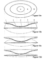
- FIG 13 schematically shows an exemplary embodiment using three capacitive sensors 4, 9 and 10.
- Each capacitive sensor 4, 9 and 10 preferably has a structure as shown in Figure 2 and more preferably a structure as shown in Figure 3 .
- the capacitive sensor 4 consists of the electrodes 4a and 4b
- the capacitive sensor 9 consists of the electrodes 9a and 9b
- the capacitive sensor 10 consists of the electrodes 10a and 10b.
- the capacitive sensors 4, 9 and 10 are located on a ram 3 which has a curved surface.
- the capacitive sensors 4, 9 and 10 are arranged in a concentric manner, which means that the capacitive sensor 9 completely surrounds the capacitive sensor 2 and the capacitive sensor 10 completely surrounds the capacitive sensor 9.
- the thickness of the ram 3 is highest. Moving away from the area at which the capacitive sensor 4 is located, the thickness of the ram 3 is gradually reduced.
- the graphs in Figure 14 show the capacities, which correspond to the output signals, of the capacitive sensors 4, 9 and 10 as shown in Figure 13 . It can be seen that the capacity of the capacitive sensor 10 starts decreasing at a higher fill level than the capacity of the capacitive sensor 9, which in turn starts decreasing at a higher fill level than the capacity of the capacitive sensor 4. With the graphs shown in Figure 14 , the fill level of the flexible medicine reservoir 1 can be determined with high accuracy in a fill level range larger than using only one capacitive sensor.
- Figure 15 shows a similar arrangement to that in Figure 13 , but using three galvanic switches made up of contacts 11a and 11b, 12a and 12b, 13a and 13b, respectively, as well as an electrically conductive coating on parts of the surface of the flexible medicine reservoir 1.
- all three pairs of connectors 11a and 11b, 12a and 12b as well as 13a and 13b are electrically shortened by the conductive coating on the reservoir.
- the contacts 13a and 13b are not shortened any longer.
- the contacts 12a and 12b are not shortened anymore.
- the contacts 11a and 11b are not shortened anymore.
- the pairs of contacts might be replaced by one common contact and one or more dedicated contact, wherein a switch is made up of the combination of the common contact and one of the dedicated contacts.
- the graph representing the conductivities between the pairs 11a and 11b, 12a and 12b as well as 13a and 13b of conductors over the fill level is similar to the graph shown in Figure 14 , which represents the capacity over the fill level.
- the difference is that the drop in conductivity is step-like, while the decrease in capacity exhibits a continuous slope. That is, the output signal of the release detectors being switches is binary.
- Figure 16a shows an exemplary embodiment using an optical detector as a release detector.
- the optical detector consists of a light source 14 and a light detector 15, in the present example being a light emitting diode (LED) and a photodiode or a phototransistor, respectively.
- the light source 14 illuminates a part of the surface of the flexible medicine reservoir 1, for example with light in the visible and/or infrared spectrum.
- the stop surface on the ram 3 is in close contact with the reservoir 1, the light emitted from the light source 14 does not reach the light sensor 15.
- the light emitted from the light source 14 is reflected by the reservoir 1 and reaches the light detector 15.
- the output signal of the light detector 15 depends on whether light is reflected onto the detector 15, which is equivalent to whether the ram 3 is in contact with the reservoir 1 or not.
- the output signal of the light detector 15 can also cover a range of output values depending on the distance between the stop surface and the flexible medicine reservoir 1, thus depending on the amount of light reflected onto the light detector 15.
- the light source 14 and the light detector 15 are arranged on or in the ram 3 with a distance to the stop surface on the ram 3. Channels in the ram between the light source 14 and the stop surface as well as the stop surface and the light detector 15, respectively, collimate the light and block stray light from influencing the detection result.
- the surface area of the flexible medicine reservoir reflecting the light optionally exhibits a reflective coating.
- the light source and the light detector form a light barrier monitoring the space between the stop surface and the reservoir. If the stop surface and the reservoir are in contact, the light barrier is interrupted. If they are not in contact, then the light barrier is not interrupted.
- Figure 17 illustrates a method for determining the fill level of the flexible medicine reservoir.
- the fill level of the flexible medicine reservoir 1 has a threshold level, in the example shown in Figures 5 and 6 this is a fill level of 110 units.
- this fill level can reliably determined independent of the fill level of the flexible medicine reservoir 1 when it was inserted into the injection device.
- This threshold fill level is then used as an initial fill level or starting fill level from which the amount of medicine pumped by the pump is subtracted.
- an interval pump as disclosed in the document EP 1 970 677 A1 is used.
- Each arrow indicates one pump cycle. In each pump cycle, a piston of the pump moves within a chamber such that a volume of the chamber is increased and the medicine is taken from the flexible medicine reservoir 1. When a certain volume is reached, the piston is pushed such that the size of the chamber decreases and the medicine within the chamber is delivered to a patient. This cycle is then repeated.
- the amount of medicine delivered during each cycle is known.
- the remaining fill level of the flexible medicine reservoir 1 is then the initial fill level detected using the release detector 2 minus the number of pump cycles times the amount of medicine delivered during each cycle.
- Figure 18 shows an exemplary circuit diagram of a converter converting the capacity C of the capacitive sensor 4 into an output voltage U.
- X5 and X6 indicate the connectors for the capacitive sensor 4
- X1 and X2 denote the connections for the supply
- X3 and X4 denote the output connections for the voltage U.
- C OSC denotes the reference capacity used for eliminating environmental factors such as temperature, humidity and electromagnetic distortion.
- R emv denotes a protective circuit against electromagnetic distortion.
- FIG 19 shows a schematic block diagram of a medical infusion device.
- the device comprises a processing unit 16, which controls a pump 17.
- the processing unit 16 is connected to the release detector 2.
- the medical infusion device accommodates the flexible medicine reservoir 1.
- the pump 17 pumps, under the control of the processing unit 16, the contents of the flexible medicine reservoir 1. This is indicated by the dashed line between the pump 17 and the flexible medicine reservoir 1.
- the release detector 2 is arranged to monitor the contact of the stop surface with the flexible medicine reservoir 1. This is shown by the dashed line between the release detector 2 and the flexible medicine reservoir 1.
- the processing unit 16 determines the fill level of the flexible medicine reservoir 1 from the output signal of the release detector 2 as explained above.
Abstract
- a stop surface designed and arranged such that the stop surface contacts the flexible medicine reservoir while the reservoir is filled above a predetermined level,
- a release detector (2) arranged on the stop surface and configured to generate an output signal indicative of the contact between the slop surface and the flexible medicine reservoir being released, and
- a processing unit (16) for determining the fill level of the flexible medicine reservoir from the output signal of the release detector.
Description
- The present invention relates to a device and a method for determining the fill level of a flexible medicine reservoir and a medical infusion device comprising such a device.
- A typical medical infusion device, for example for delivering insulin, usually comprises a rigid container for the medicine. Typical containers are syringes or other volumes having a plunger for administering medicine. According to standards for medical electrical equipment, it is necessary to cause an alert if the fill level of the medicine reservoir falls to a certain level. For a rigid medicine container, the fill level can be determined from the position of the plunger within the container. However, medical infusion devices with a rigid container are limiting to the design of the infusion device and, for a given maximum size of the infusion device, are limited in the amount of medicine they can carry.
- These design drawbacks can be overcome by using a flexible medicine reservoir which can better utilize the available space within the infusion device. With a flexible medicine reservoir, like a bag, it is favorable not to push the medicine out of the container by forcing a plunger forwards, but to pump it out the container via suction pressure. One possible pump for this type of design is disclosed in the
European patent application 1 970 677 A1 . This pump is, at the same time, a dosing device. This concept is called downstream dosing. The pump fills its chamber from the medicine reservoir and then empties this chamber by administering the medicine in small increments of the chamber volume. This cycle is then repeated. - With a flexible medicine reservoir, there is no plunger whose position could be used for determining the fill level of the medicine reservoir. One possibility would be to integrate the amount of delivered medicine. But this has the drawback that only the amount of medicine taken from the reservoir can be determined, but not the amount of remaining medicine. This is an issue in particular if the initial fill level of the reservoir can vary. In addition, there can be a difference between the amount of medicine to be delivered and the actual amount delivered, which sums up during integration. This means that the medical infusion device could cause an alert even though the reservoir is not emptied to the level where an alert should be generated, or, which is even worse, could not cause an alert even though the reservoir is emptied below that level and may even be completely empty.
- It is therefore the object of the present invention to provide a device and a method for determining the fill level of a flexible medicine reservoir, or at least for determining if the fill level of a flexible medicine reservoir has fallen to or below a threshold level.
- As used herein, the term "medicine" encompasses any drug-containing flowable medicine, or therapeutic or diagnostic liquid, which can be delivered to a patient. In particular, this term encompasses insulin preparations ready for administration.
- The device for determining the fill level of a flexible medicine reservoir according to the present invention comprises a stop surface designed and arranged such that the stop surface contacts the flexible medicine reservoir while the reservoir is filled above a predetermined level; a release detector arranged and configured to generate an output signal indicative of the contact between the stop surface and the flexible medicine reservoir being released; and a processing unit for determining the fill level of the flexible medicine reservoir from the output signal of the release detector.
- The stop surface can be a sensitive part of the release detector, a surface connected to the sensitive part of the release detector or a surface covering the sensitive part of the release detector. The sensitive part, or sensitive area, is a part or area of the release detector which is sensitive for a physical value and which is used for generating the output signal.
- The stop surface is completely in contact with the flexible medicine reservoir as long as the reservoir is filled above a predetermined level. This means that the whole area of the stop surface is in contact with the flexible medicine reservoir. The predetermined level represents an absolute amount of medicine left in the reservoir. Once the fill level falls below the predetermined level, the contact between the stop surface and the flexible medicine reservoir starts to release. This means that the contact area between the stop surface and the reservoir remains constant until the predetermined fill level is reached, then progressively decreases until the size of the area is zero, which means that there is no remaining contact between the stop surface and the reservoir.
- The output signal of the release detector being indicative of the contact between the stop surface and the flexible medicine reservoir being released means that the signal indicates that (i) the contact starts to release at the beginning of the release process, (ii) is fully released at the end of the release process, (iii) corresponds to a remaining contact area size during the release process or (iv) corresponds to the distance between the stop surface and the flexible medicine reservoir. The output signal can also indicate one or more of these states.
- From this output signal, the processing unit determines the fill level of the flexible medicine reservoir. In a simple embodiment, the processing unit is configured to determine whether the fill level has fallen to or below the threshold or not. The threshold can equal the predetermined fill level, which means that this threshold has been reached when the contact between the stop surface and the flexible medicine reservoir starts to release. As an alternative, the threshold can be a fill level at which the release process ends, which means the fill level at which the contact area size has just fallen to zero. As a further alternative, the threshold is at an intermediate point between the beginning and the end of the contact release process. This is possible if the release detector outputs a signal which corresponds to the actual fill level of the flexible medicine reservoir, for example by an unambiguous, in particular continuous manner.
- This means that there are actually two fill levels of the flexible medicine reservoir of interest. The first level is the predetermined fill level at which the contact between the stop surface and the reservoir starts being released and the second level is the threshold level which is an absolute fill level to be detected. As explained above, these two fill levels may coincide.
- As an option, the processing unit is configured to take into account information on the amount of medicine pumped from the flexible medicine reservoir by a pump. This information can be provided by the control unit of the pump. The control unit might be the same as the processing unit for determining the fill level. Preferably, taking the additional information into account starts when the device has determined that the threshold has been reached.
- This means that the processing unit starts summing or integrating the amount of pumped medicine once the threshold level has been reached. The fill level of the reservoir is then calculated by subtracting the summed or integrated amount of pumped medicine from the threshold level. In this case, a possibly present integration error as discussed above, resulting, e.g., from difference between the nominal and the actual chamber volume of the pump, is not too critical since the integration only starts at a comparatively low filling level of the reservoir. Thus, the resulting total error is limited.
- If an interval pump as described in
document EP 1 970 677 A1 is used, the fill level of the flexible medicine reservoir can in general be determined at any point within the interval, but is preferably determined when the chamber of the pump is completely filled or completely empty. - In a preferred embodiment, the release detector is a capacitive sensor consisting of at least two electrodes. The electrodes are designed such that the electrical field between them extends at least partially to the flexible medicine reservoir. The electrical field between the electrodes extending to the flexible medicine reservoir means that at least parts of the electrical field extend into the reservoir or at least to the surface of the reservoir. The stop surface can comprise the surface of the electrodes or can be a surface covering the electrodes.
- A change of the fill level of the flexible medicine reservoir leads to a decrease of the contact area between the stop surface and the flexible medicine reservoir or an increase in the distance between the stop surface and the flexible medicine reservoir. This results in a changed capacity of the capacitive sensor. From the capacity of the capacitive sensor, the fill level of the flexible medicine reservoir can be determined, for example from a look-up table containing pairs of a capacity and a corresponding fill level or a graph representing the correlation of the capacity and the fill level.
- The electrodes can be area electrodes. This means that an electrode has a length and a width which are significantly larger than the widths of the conductors connecting the electrode. The electrodes can be plane or have a curved surface.
- As an alternative, an electrode consists of a plurality of fingers or a meandering conductor. The plurality of fingers is preferably arranged in parallel, such that the electrode has the shape of a rake. An electrode being a meandering conductor has a shape of a spiral. If both electrodes have the same shape, either of a rake or a spiral, the electrodes can be intertwined, leading to a capacity which can reliably be detected and analyzed.
- In an alternative embodiment, the release detector is a pressure sensor or a force sensor. A force sensor outputs an output signal which corresponds to the force exerted on the sensitive area of the force sensor. A pressure sensor outputs an output signal which corresponds to the force exerted on the sensitive area of the pressure sensor divided by an area size, for example the size of the sensitive area. Preferably, the sensitive area of the force or pressure sensor is the stop surface or is in rigid contact with the stop surface. A force sensor or a pressure sensor may be a foil-like element, which is flexible and therefore easy to place on a surface with arbitrary shape. The sensor may also be a force sensitive resistor.
- As a further alternative embodiment, the release detector is an optical detector. An optical detector comprises at least one light source and at least one light detector. The light source emits light in the visible and/or invisible spectrum onto or along the flexible medicine reservoir and the light detector outputs an output signal indicative of the amount of light received from the light source. In one embodiment, the output signal is a binary signal, indicating whether the light path between the light source and the light detector is obstructed or not. In this embodiment, the optical detector works like a light barrier. In an alternative embodiment, the output signal of the light detector can have a continuous range corresponding to the amount of light received. In this embodiment, intermediate fill levels can be determined, while the first embodiment only allows for detection of a threshold. Preferably, the surface of the flexible medicine reservoir is at least partly covered with a reflective coat for reflecting the light emitted by the light source. The coated area reflects the light of the light source onto the light sensor depending on the fill level of the flexible medicine reservoir.
- The release detectors described so far, that is the capacitive sensor, the pressure sensor, the force sensor and the optical detector, can provide an output signal covering a continuous range of output values, for example voltages. The range of the output values corresponds to a range of fill levels of the flexible medicine reservoir. The relation can be described by a graph or a look-up table, for example. The fill level of the flexible medicine reservoir can then be determined from the graph or the look-up table.
- In one embodiment, the derivation of the output signal of the release detector is calculated. Then, for example, an extremum of this derivation can be found, wherein the threshold of the fill level preferably is reached when the derivation of the release detector output signal has its extremum. In this example, the release detector is preferably designed such that its output signal changes strongest, which means as a maximum in its derivation, at or close to the threshold of the fill level.
- In another embodiment, the release detector is a switch. In this document, the term "switch" means a device which opens or closes an electrical circuit depending on whether the stop surface is in contact with the flexible medicine reservoir or not. For example, the switch can be a micro-switch or a foil switch. As another example, the switch can comprise two galvanic contacts on the stop surface and a conducting, for example metalized, surface area of the flexible medicine reservoir. This conducting surface opens or closes the electrical connection between the two connectors depending on the fill level of the flexible medicine reservoir. If the fill level of the flexible medicine reservoir is above the threshold, the conducting surface area contacts both contacts and therefore electrically bridges these contacts. If the fill level falls below the threshold, this electrical bridge is opened.
- The stop surface can be flat or curved to adapt the correlation between the output signal and the fill level of the flexible medicine reservoir. If this correlation is represented by a graph, the progression of the graph changes depending on the curvature of the stop surface.
- In an advantageous design, the stop surface is located on a ram which pushes against the flexible medicine reservoir as long as the flexible medicine reservoir is filled above the predetermined level. The ram pushing against the flexible medicine reservoir means that the ram, or the stop surface located on the ram, is in direct contact with the reservoir for a wide range of fill levels of the reservoir. Preferably, the ram exerts a non-negligible force onto the reservoir and potentially deforms it. In this range, the output signal of the release detector remains basically constant and only starts changing when the stop surface loses contact with the reservoir.
- As an option, the ram is arranged within a housing of the medical infusion device such that the flexible medicine reservoir can move the ram. Preferably, the ram is spring-loaded, wherein the spring pushes the ram against the flexible medicine reservoir. Further preferably, there is a mechanical stop limiting the movement of the ram towards the flexible medicine reservoir. With this arrangement, the ram pushes into the flexible medicine reservoir for a wide range of fill levels, without the danger of damaging the reservoir if the fill level is very high.
- In an alternative embodiment, the release detector providing the stop surface is a part of a housing which houses the flexible medicine reservoir. This housing typically is the housing of the medical infusion device, accommodating not only the flexible medicine reservoir and the device for determining the fill level, but usually also other components like a battery or a pump.
- In an embodiment of the present invention, the device comprises a plurality of release detectors. Preferably, the plurality of release detectors is configured to cover different areas of the flexible medicine reservoir, for example by monitoring different sub-areas of the stop surface. For example, the sub-areas form a stop surface which is shaped such that the sub-areas lose contact to the flexible medicine reservoir one after the other when the fill level decreases. The plurality of sub-areas can be monitored by only one type of release detector or two or more types of release detectors.
- In a preferred constellation of the device with a plurality of capacitve sensors, the sensors are arranged in a concentric pattern. This means that a first, innermost sensor is completely or almost completely surrounded by another sensor. An optional third sensor completely or almost completely surrounds these two sensors, and so on. Preferably, the innermost sensor is located on the ram such that it is the last sensor to lose contact with the flexible medicine reservoir when the reservoir is being emptied.
- When a plurality of measurement capacitors is used, two or more of these capacitors can use a shared electrode. The same applies if a plurality of switches is used.
- In a preferred embodiment, the device also comprises a reference capacitor. The capacity of the capacitive sensor is compared to the known capacity of the reference capacitor, resulting in relative measurement values. With the reference capacitor, environmental factors such as temperature, humidity or electromagnetic distortion have a reduced or no impact on the accuracy of the determined fill level. The reference capacitor should be physically located as close to the capacitive sensor as possible, but without causing interference between the capacitors. The reference capacitor can have area, finger-shaped or meandering electrodes.
- As an additional option, an electromagnetic shielding for the capacitors can be provided.
- Preferably, the device is designed such that the change in the output signal of the release detector is largest around the threshold for the fill level. In this case, the threshold of the fill level is reached when the derivation of the output signal over time has a maximum.
- Optionally, the device is configured to cause an alert if the fill level of the flexible medicine reservoir reaches a particular level. This particular level can equal the predetermined level or the threshold level.
- The present invention also relates to a method for determining the fill level of a flexible medicine reservoir, comprising the steps of determining when a threshold fill level of the flexible medicine reservoir has been reached, determining the amount of medicine taken from the flexible medicine reservoir since the threshold fill level has been reached and calculating the fill level by subtracting the determined amount of medicine taken from the flexible medicine reservoir from the threshold fill level. The threshold level can, but not necessarily must be the predetermined fill level at which a contact between a stop surface and the flexible medicine reservoir starts to release. In particular, a device as described above is used for implementing the method.
- In a preferred embodiment of the method, determining when a threshold fill level is reached is performed based on the output signal of a release detector indicative of the contact between a stop surface and the flexible medicine reservoir being released, wherein the stop surface is designed and arranged such that the stop surface contacts the flexible medicine reservoir while the reservoir is filled above a predetermined level.
- In a preferred embodiment, the processing unit for determining the fill level from the output signal of the release detector is the control unit of the medical infusion device used for controlling the pump.
- The present invention also relates to a system comprising the device for determining the fill level of a flexible medicine reservoir and a flexible medicine reservoir.
- The present invention further relates to a medical infusion device which is configured to receive a flexible medicine reservoir, comprising a device for determining the fill level of the flexible medicine reservoir as explained above.
- Several exemplary embodiments are now described referring to the appended drawings. These drawings show:
- Figure 1
- an arrangement with two electrodes located on a ram pushing into a flexible medicine reservoir,
- Figure 2
- two rake-shaped electrodes,
- Figure 3
- two meandering electrodes,
- Figure 4
- an electrical field between two electrodes,
- Figure 5
- a measured graph of a voltage corresponding to a capacity over the fill level,
- Figure 6
- the derivation of the graph of
Figure 5 , - Figure 7
- the dimensions of two intertwined, meandering electrodes,
- Figure 8
- width of and distance between the electrodes shown in
Figure 7 , - Figure 9
- a ram carrying two electrodes on a flat surface,
- Figure 10
- two electrodes on a curved surface of a ram,
- Figure 11
- an idealized curve of the capacity over the fill level,
- Figure 12
- variations of the graph of
Figure 11 , - Figure 13
- three concentric measurement capacitors,
- Figure 14
- an idealized curve of the capacity over the fill level for the arrangement of
Figure 13 , - Figure 15
- three concentric galvanic switches,
- Figure 16
- an optical detector as release detector,
- Figure 17
- an illustration of a fill level determining method,
- Figure 18
- a circuit for transforming a capacity into a voltage and
- Figure 19
- a schematic block diagram of a medical infusion device.
-
Figure 1 shows an arrangement in which arelease detector 2 is located on aram 3 which pushes into aflexible medicine reservoir 1 such that a stop surface, which in the present arrangement is a sensitive area of therelease detector 2, is in full contact with thereservoir 1 as long as the fill level of the reservoir is above a predetermined fill level. The term "full contact" means that the whole stop surface is in contact with the flexible medicine reservoir. - This arrangement has the advantage that the stop surface remains in contact with the
flexible medicine reservoir 1 over a wide range of fill levels. Once the fill level has fallen to a predetermined fill level, the contact of therelease detector 2, and therefore of the stop surface, with the surface of theflexible medicine reservoir 1 is gradually released, which means that from this point on the output signal of therelease detector 2 rapidly changes, while it was basically constant up to this point. When theflexible medicine reservoir 1 is empty, the distance between thereservoir 1 and therelease detector 2 is e. The parameter e is chosen such that the forces exerted from a full reservoir on the ram and the housing do not get too strong. For miniaturization reasons, a small value for e in the range of typically 1 mm to 5mm is generally preferred. Other values, however, are possible as well. - In the first exemplary embodiment, the
release detector 2 is acapacitive sensor 4 consisting of theelectrodes electrodes Figures 2 and 3 show alternative shapes for the electrodes. InFigure 2 , theelectrodes electrodes Figure 3 , theelectrodes electrodes electrodes -
Figure 4 schematically shows the principle of the device according to the first exemplary embodiment. Theflexible medicine reservoir 1 consists of abag 5 filled withinsulin 6. The electric flux lines between theelectrodes lines 7. At the fill level shown inFigure 4 , the electrical field between theelectrodes gap 8, e.g. filled with air, into theflexible medicine reservoir 1 such that it passes thebag 5 and theinsulin 6. Depending on the fill level of theflexible medicine reservoir 1, the composition of materials in the electrical field between theelectrodes capacitive sensor 4 depending on the fill level of theflexible medicine reservoir 1. - In the embodiment shown in
Figure 4 , the stop surface is the surface of an isolator in which theelectrodes - If the flexible medicine reservoir is filled above a certain fill level, for example the predetermined fill level, the size of the
gap 8 is zero, which means that the stop surface is lying flat on theflexible medicine reservoir 1. While thereservoir 1 is emptied, the contact area of the stop surface with thereservoir 1 decreases until the contact is completely lost and there is no more physical contact. From then on, only the width of thegap 8 increases if the reservoir is further emptied. -
Figure 5 shows several measured graphs representing a voltage U, which corresponds to the capacity C of thecapacitive sensor 4, over the fill level of the flexible medicine reservoir. The fill level V is given in standardized volume units of the medicine, for example insulin. - For the graphs shown in
Figure 5 , the electrodes as shown inFigure 3 are arranged on a flat surface of theram 3 pushing against the reservoir as shown inFigure 1 . As can be seen fromFigure 7 , the area covered by the intertwinedelectrodes Figure 8 , the conductors forming theelectrodes electrodes Figure 5 are a = 15 mm, b = 28 mm, c = 0,8 mm, d = 0,8 mm and e = 1 mm. Typical parameters of a flexible medicine reservoir are a size of 42 x 33 mm and a maximum fill level between 100 and 500 units, for example 300 units, for the standard insulin concentration U100. - As can be seen from
Figure 5 , the voltage U, and therefore the capacity C of thecapacitive sensor 4, remains basically constant up to a point at which theflexible medicine reservoir 1 is emptied to a fill level of about 150 units. From this fill level on, the stop surface loses contact with the surface of theflexible medicine reservoir 1, which means that at least parts of the electrical field between the electrodes extend through air before they reach the reservoir. Further emptying of the reservoir leads to a decrease in capacity C, and therefore of the voltage U, until the gap between the electrodes and the reservoir has reached a size at which the electrical field between the electrodes extends through the air in the most part and only a small amount penetrates theflexible medicine reservoir 1. This happens at a fill level of about 60 units. Further emptying of the reservoir does not further decrease the capacity of thecapacitive sensor 4. So this means that only in a fill level range between 150 units and 60 units the capacity C and therefore the voltage U decreases. -
Figure 6 shows the negative derivation of the graphs shown inFigure 5 over the fill level V of theflexible medicine reservoir 1. It can be seen that all graphs inFigure 6 have a maximum at about 110 units. This means that the decrease in capacity C at a fill level V of 110 unit is highest. - In a preferred embodiment, the amount of medicine pumped by the pump which empties the
flexible medicine reservoir 1 is taken into account for determining the fill level V starting from a point at which the negative derivation shown inFigure 6 reaches a peak, i.e. a point at which the change in capacity C of thecapacitive sensor 4 is highest. The fill level V at which the peak occurs is known, such that this fill level can be used as a starting point for fill level determination using the relative information about the amount of delivered medicine. The fill level can be determined by subtracting the integrated amount of delivered medicine from a threshold fill level, wherein this threshold fill level preferably is the fill level at which the peak inFigure 13 occurs. - Graphs very similar to those shown in
Figures 5 and 6 result if thecapacitive sensor 4 is replaced by a force sensor as therelease detector 2 and theram 3 is spring-loaded. -
Figure 9 shows an exemplary embodiment of aram 3 carrying theintertwined electrodes Figure 10 shows theelectrodes -
Figure 11 shows an idealized version of the graph shown inFigure 5 , depicting the capacity C of acapacitive sensor 4 over the decreasing fill level V of theflexible medicine reservoir 1. In thefill level range 1, the reservoir is quite full and theram 3 with theelectrodes fill level range 2, the contact area between the stop surface and theflexible medicine reservoir 1 continuously decreases, generating a distance between the reservoir and the electrodes. In this range, the decrease in capacity is strongest. In thefill level range 3, the distance between the electrodes and the reservoir is so large such that theflexible medicine reservoir 1 as the dielectric has almost no influence on the capacity C. - In
Figure 11 , ΔC denotes the maximum difference in capacity which occurs during the measurement, i.e. between a completely filled and a completely empty reservoir. The term "offset" denotes the minimum capacity C of thecapacitive sensor 4, having only air with a permittivity of 1 as the dielectric. -
Figure 12 shows modifications to the graph shown inFigure 11 . In the upper left ofFigure 12 , a graph is shown with ΔC as inFigure 11 . In the upper right, ΔC was enhanced by a further +ΔC, which means that the range ΔC of the capacity C of thecapacitive sensor 4 is increased. This can, for example, be achieved by reducing the width d of the conductor forming the electrodes. From the upper right to the lower right ofFigure 12 , the slope of the graph was reduced, i.e. thefill level range 2 as shown inFigure 11 was expanded. Therange 2 is expanded by +ΔV to the left as well as to the right. This can be achieved, for example, by amending the surface curvature of theram 3 on which theelectrodes -
Figure 13 schematically shows an exemplary embodiment using threecapacitive sensors capacitive sensor Figure 2 and more preferably a structure as shown inFigure 3 . Thecapacitive sensor 4 consists of theelectrodes capacitive sensor 9 consists of the electrodes 9a and 9b and thecapacitive sensor 10 consists of the electrodes 10a and 10b. - As can be seen from
Figure 13b , thecapacitive sensors ram 3 which has a curved surface. Thecapacitive sensors capacitive sensor 9 completely surrounds thecapacitive sensor 2 and thecapacitive sensor 10 completely surrounds thecapacitive sensor 9. In the area in which thecapacitive sensor 4 is located, the thickness of theram 3 is highest. Moving away from the area at which thecapacitive sensor 4 is located, the thickness of theram 3 is gradually reduced. - In the state shown in
Figure 13b , theflexible medicine reservoir 1 is completely filled. In this state, thecapacitive sensors capacitive sensor 10 is only partly in contact with the reservoir. In the state shown inFigure 13c , the fill level of theflexible medicine reservoir 1 is reduced. In this state, only thecapacitive sensor 4 is completely in contact with the reservoir. Thecapacitive sensor 10 has no contact with the reservoir and thecapacitive sensor 9 is only partly in contact with the reservoir. - In the state shown in
Figure 13d , the fill level of theflexible medicine reservoir 1 is further reduced. In this state, thecapacitive sensor 4 is fully in contact with the reservoir, while thecapacitive sensors flexible medicine reservoir 1 is further emptied (not shown), also the contact of thecapacitive sensor 4 with theflexible medicine reservoir 1 starts to release. - With the configuration as shown in
Figure 13a , it is possible to determine the fill level of the flexible medicine reservoir over a large fill level range by analyzing the capacity of all threecapacitive sensors Figure 13a . - The graphs in
Figure 14 show the capacities, which correspond to the output signals, of thecapacitive sensors Figure 13 . It can be seen that the capacity of thecapacitive sensor 10 starts decreasing at a higher fill level than the capacity of thecapacitive sensor 9, which in turn starts decreasing at a higher fill level than the capacity of thecapacitive sensor 4. With the graphs shown inFigure 14 , the fill level of theflexible medicine reservoir 1 can be determined with high accuracy in a fill level range larger than using only one capacitive sensor. -
Figure 15 shows a similar arrangement to that inFigure 13 , but using three galvanic switches made up ofcontacts flexible medicine reservoir 1. In the state of theflexible medicine reservoir 1 as shown inFigure 15 , all three pairs ofconnectors Figures 13b to 13d , at a certain fill level thecontacts contacts contacts Figure 15 , the pairs of contacts might be replaced by one common contact and one or more dedicated contact, wherein a switch is made up of the combination of the common contact and one of the dedicated contacts. - The graph representing the conductivities between the
pairs Figure 14 , which represents the capacity over the fill level. The difference is that the drop in conductivity is step-like, while the decrease in capacity exhibits a continuous slope. That is, the output signal of the release detectors being switches is binary. -
Figure 16a shows an exemplary embodiment using an optical detector as a release detector. The optical detector consists of alight source 14 and alight detector 15, in the present example being a light emitting diode (LED) and a photodiode or a phototransistor, respectively. Thelight source 14 illuminates a part of the surface of theflexible medicine reservoir 1, for example with light in the visible and/or infrared spectrum. In the state shown inFigure 16a , in which the stop surface on theram 3 is in close contact with thereservoir 1, the light emitted from thelight source 14 does not reach thelight sensor 15. - In the state shown in
Figure 16b , with a gap between theram 3 and thereservoir 1, the light emitted from thelight source 14 is reflected by thereservoir 1 and reaches thelight detector 15. The output signal of thelight detector 15 depends on whether light is reflected onto thedetector 15, which is equivalent to whether theram 3 is in contact with thereservoir 1 or not. The output signal of thelight detector 15 can also cover a range of output values depending on the distance between the stop surface and theflexible medicine reservoir 1, thus depending on the amount of light reflected onto thelight detector 15. - In the present case, the
light source 14 and thelight detector 15 are arranged on or in theram 3 with a distance to the stop surface on theram 3. Channels in the ram between thelight source 14 and the stop surface as well as the stop surface and thelight detector 15, respectively, collimate the light and block stray light from influencing the detection result. To further increase the reliability of the detection result, the surface area of the flexible medicine reservoir reflecting the light optionally exhibits a reflective coating. - In an alternative embodiment (not shown), the light source and the light detector form a light barrier monitoring the space between the stop surface and the reservoir. If the stop surface and the reservoir are in contact, the light barrier is interrupted. If they are not in contact, then the light barrier is not interrupted.
-
Figure 17 illustrates a method for determining the fill level of the flexible medicine reservoir. When the negative derivative of the capacity as shown inFigure 6 has reached a peak, it is known that the fill level of theflexible medicine reservoir 1 has a threshold level, in the example shown inFigures 5 and 6 this is a fill level of 110 units. With therelease detector 2, this fill level can reliably determined independent of the fill level of theflexible medicine reservoir 1 when it was inserted into the injection device. - This threshold fill level is then used as an initial fill level or starting fill level from which the amount of medicine pumped by the pump is subtracted. In the example illustrated in
Figure 17 , an interval pump as disclosed in thedocument EP 1 970 677 A1 is used. Each arrow indicates one pump cycle. In each pump cycle, a piston of the pump moves within a chamber such that a volume of the chamber is increased and the medicine is taken from theflexible medicine reservoir 1. When a certain volume is reached, the piston is pushed such that the size of the chamber decreases and the medicine within the chamber is delivered to a patient. This cycle is then repeated. - Due to the known volume of the pump chamber, the amount of medicine delivered during each cycle is known. The remaining fill level of the
flexible medicine reservoir 1 is then the initial fill level detected using therelease detector 2 minus the number of pump cycles times the amount of medicine delivered during each cycle. -
Figure 18 shows an exemplary circuit diagram of a converter converting the capacity C of thecapacitive sensor 4 into an output voltage U. X5 and X6 indicate the connectors for thecapacitive sensor 4, X1 and X2 denote the connections for the supply and X3 and X4 denote the output connections for the voltage U. COSC denotes the reference capacity used for eliminating environmental factors such as temperature, humidity and electromagnetic distortion. Remv denotes a protective circuit against electromagnetic distortion. -
Figure 19 shows a schematic block diagram of a medical infusion device. The device comprises aprocessing unit 16, which controls apump 17. Theprocessing unit 16 is connected to therelease detector 2. The medical infusion device accommodates theflexible medicine reservoir 1. Thepump 17 pumps, under the control of theprocessing unit 16, the contents of theflexible medicine reservoir 1. This is indicated by the dashed line between thepump 17 and theflexible medicine reservoir 1. Therelease detector 2 is arranged to monitor the contact of the stop surface with theflexible medicine reservoir 1. This is shown by the dashed line between therelease detector 2 and theflexible medicine reservoir 1. Theprocessing unit 16 determines the fill level of theflexible medicine reservoir 1 from the output signal of therelease detector 2 as explained above.
Claims (14)
- Device for determining the fill level of a flexible medicine reservoir (1), comprising- a stop surface designed and arranged such that the stop surface contacts the flexible medicine reservoir (1) while the reservoir (1) is filled above a predetermined level,- a release detector (2) configured to generate an output signal indicative of the contact between the stop surface and the flexible medicine reservoir (1) being released, and- a processing unit (16) for determining the fill level of the flexible medicine reservoir (1) from the output signal of the release detector (2).
- Device as claimed in claim 1, wherein the release detector (2) is a capacitive sensor (4, 9, 10) consisting of at least two electrodes (4a, 4b).
- Device as claimed in claim 2, wherein each electrode (4a, 4b) consists of a plurality of fingers or a meandering conductor and wherein the electrodes (4a, 4b) an intertwined.
- Device as claimed in one of claims 1 to 3, wherein the release detector (2) is a pressure sensor or a force sensor.
- Device as claimed in one of claims 1 to 4, wherein the release detector (2) is an optical detector (14, 15).
- Device as claimed in one of claims 1 to 5, wherein the release detector (2) is a switch (11, 12, 13).
- Device as claimed in one of claims 1 to 6, wherein the stop surface is located on a ram (3) which pushes against the flexible medicine reservoir (1) as long as the flexible medicine reservoir (1) is filled above the predetermined level.
- Device as claimed in one of claims 1 to 7, wherein the stop surface is a part of a housing which houses the flexible medicine reservoir (1).
- Device as claimed in one of claims 1 to 8, comprising a plurality of release detectors.
- Device as claimed in one of claims 1 to 9, wherein the processing unit (16) is configured to determine whether the fill level has fallen to or below a threshold or not.
- Device as claimed in one of claims 1 to 10, wherein the processing unit (16) is configured to take into account information on the amount of medicine pumped from the flexible medicine reservoir (1) by a pump (17).
- Medical infusion device which is configured to receive a flexible medicine reservoir (1), comprising a device for determining the fill level of the flexible medicine reservoir (1) as claimed in one of claims 1 to 11.
- Method for determining the fill level of a flexible medicine reservoir (1), comprising the steps of- determining when a threshold fill level of the flexible medicine reservoir (1) has been reached,- determining the amount of medicine taken from the flexible medicine reservoir (1) since the threshold fill level has been reached and- calculating the fill level by subtracting the determined amount of medicine taken from the flexible medicine reservoir (1) from the threshold fill level.
- Method as claimed in claim 13, wherein determining when a threshold fill level is reached is performed based on the output signal of a release detector (2) indicative of the contact between a stop surface and the flexible medicine reservoir (1) being released, wherein the stop surface is designed and arranged such that the stop surface contacts the flexible medicine reservoir (1) while the reservoir (1) is filled above a predetermined level.
Priority Applications (7)
| Application Number | Priority Date | Filing Date | Title |
|---|---|---|---|
| AT09175634T ATE538826T1 (en) | 2009-11-11 | 2009-11-11 | DEVICE AND METHOD FOR DETERMINING THE FILL LEVEL OF A FLEXIBLE MEDICATION RESERVOIR |
| DK09175634.6T DK2327435T3 (en) | 2009-11-11 | 2009-11-11 | Apparatus and method for determining the filling level of a flexible medicine reservoir |
| EP09175634A EP2327435B1 (en) | 2009-11-11 | 2009-11-11 | Device and method for determining the fill level of a flexible medicine reservoir |
| DK10189152.1T DK2322238T3 (en) | 2009-11-11 | 2010-10-28 | Device and method for determining the filling level of a flexible drug container |
| EP10189152.1A EP2322238B1 (en) | 2009-11-11 | 2010-10-28 | Device and method for determining the fill level of a flexible medicine reservoir |
| US12/943,405 US8286484B2 (en) | 2009-11-11 | 2010-11-10 | Device and method for determining the fill level of a flexible medicine reservoir |
| US13/617,948 US8516883B2 (en) | 2009-11-11 | 2012-09-14 | Device and method for determining the fill level of a flexible medicine reservoir |
Applications Claiming Priority (1)
| Application Number | Priority Date | Filing Date | Title |
|---|---|---|---|
| EP09175634A EP2327435B1 (en) | 2009-11-11 | 2009-11-11 | Device and method for determining the fill level of a flexible medicine reservoir |
Publications (2)
| Publication Number | Publication Date |
|---|---|
| EP2327435A1 true EP2327435A1 (en) | 2011-06-01 |
| EP2327435B1 EP2327435B1 (en) | 2011-12-28 |
Family
ID=42126390
Family Applications (2)
| Application Number | Title | Priority Date | Filing Date |
|---|---|---|---|
| EP09175634A Active EP2327435B1 (en) | 2009-11-11 | 2009-11-11 | Device and method for determining the fill level of a flexible medicine reservoir |
| EP10189152.1A Active EP2322238B1 (en) | 2009-11-11 | 2010-10-28 | Device and method for determining the fill level of a flexible medicine reservoir |
Family Applications After (1)
| Application Number | Title | Priority Date | Filing Date |
|---|---|---|---|
| EP10189152.1A Active EP2322238B1 (en) | 2009-11-11 | 2010-10-28 | Device and method for determining the fill level of a flexible medicine reservoir |
Country Status (4)
| Country | Link |
|---|---|
| US (2) | US8286484B2 (en) |
| EP (2) | EP2327435B1 (en) |
| AT (1) | ATE538826T1 (en) |
| DK (2) | DK2327435T3 (en) |
Families Citing this family (17)
| Publication number | Priority date | Publication date | Assignee | Title |
|---|---|---|---|---|
| DK2196231T3 (en) * | 2008-12-12 | 2013-06-03 | Hoffmann La Roche | Outpatient drug infusion system with a flexible container filler |
| CA2739362A1 (en) * | 2011-05-06 | 2012-11-06 | Gotohti.Com Inc. | Fluid level gauge |
| EP2724739B1 (en) | 2009-07-30 | 2015-07-01 | Tandem Diabetes Care, Inc. | Portable infusion pump system |
| JP2013165757A (en) * | 2012-02-14 | 2013-08-29 | Icomes Labo:Kk | Transfusion device |
| US9180242B2 (en) | 2012-05-17 | 2015-11-10 | Tandem Diabetes Care, Inc. | Methods and devices for multiple fluid transfer |
| AT513452B1 (en) * | 2012-10-05 | 2014-08-15 | Ait Austrian Inst Technology | Dispensing device for medicaments |
| US9173998B2 (en) | 2013-03-14 | 2015-11-03 | Tandem Diabetes Care, Inc. | System and method for detecting occlusions in an infusion pump |
| US9603995B2 (en) | 2013-03-15 | 2017-03-28 | Tandem Diabetes Care. Inc. | Device and method for setting therapeutic parameters for an infusion device |
| US10130221B2 (en) | 2015-01-23 | 2018-11-20 | Gpcp Ip Holdings Llc | Optimizing a dispensing parameter of a product dispenser based on product usage data |
| WO2017048248A1 (en) * | 2015-09-16 | 2017-03-23 | Halliburton Energy Services, Inc. | Method and apparatus for measuring characteristics of fluid in a reservoir |
| US10145760B2 (en) * | 2016-01-05 | 2018-12-04 | Biosense Webster (Israel) Ltd. | Status of an irrigation pump |
| US11395566B2 (en) | 2016-04-11 | 2022-07-26 | Gpcp Ip Holdings Llc | Sheet product dispenser |
| US11412900B2 (en) | 2016-04-11 | 2022-08-16 | Gpcp Ip Holdings Llc | Sheet product dispenser with motor operation sensing |
| US10314963B2 (en) * | 2016-05-16 | 2019-06-11 | Mayo Foundation For Medical Education And Research | Medical reservoir level sensor |
| EP3290072B1 (en) | 2016-09-05 | 2019-04-10 | Roche Diabetes Care GmbH | Device for measuring a fill level of a flexible medicine reser-voir |
| US10874265B2 (en) | 2017-05-10 | 2020-12-29 | Gpcp Ip Holdings Llc | Sheet product level sensor calibration and indication systems and methods |
| US11617478B2 (en) | 2019-10-09 | 2023-04-04 | Gpcp Ip Holdings Llc | Systems and methods for product level tracking of sheet product rolls |
Citations (5)
| Publication number | Priority date | Publication date | Assignee | Title |
|---|---|---|---|---|
| US5098409A (en) * | 1991-01-04 | 1992-03-24 | Massachusetts Institute Of Technology | Intravenous bag and monitoring method |
| US6315769B1 (en) * | 1999-09-13 | 2001-11-13 | Medtronic, Inc. | Apparatus and method for measuring the amount of fluid contained in an implantable medical device |
| US20020120236A1 (en) * | 2001-02-23 | 2002-08-29 | Diaz Luis A. | Integrated medication delivery system |
| EP1818664A1 (en) * | 2006-02-13 | 2007-08-15 | F.Hoffmann-La Roche Ag | Device for detection of a change of pressure in a canal of a microdosing device |
| EP1970677A1 (en) | 2007-03-15 | 2008-09-17 | F. Hoffmann-La Roche AG | Dosing device for an intravenous infusion system |
Family Cites Families (7)
| Publication number | Priority date | Publication date | Assignee | Title |
|---|---|---|---|---|
| CH622887A5 (en) * | 1977-08-10 | 1981-04-30 | Albert Hans Fenner | Device for detecting the level of a liquid |
| US4530696A (en) * | 1983-06-13 | 1985-07-23 | Institute Of Critical Care Medicine | Monitor for intravenous injection system for detecting occlusion and/or infiltration |
| KR100675913B1 (en) * | 2005-02-14 | 2007-01-29 | 이상대 | Liquid blocking apparatus and liquid blocking monitoring apparatus equipped with an alarm or wireless calling device and a storing bag |
| US20070293817A1 (en) * | 2006-06-16 | 2007-12-20 | Jun Feng | Portable IV infusion mornitoring system |
| EP2179755B1 (en) | 2008-10-24 | 2013-03-13 | F. Hoffmann-La Roche AG | Flexible medicine reservoir with an internal reservoir port |
| EP2193815B1 (en) | 2008-12-03 | 2013-02-13 | F. Hoffmann-La Roche AG | Flexible container with a preformed fluid channel and infusion pump device using such a container |
| DK2196231T3 (en) * | 2008-12-12 | 2013-06-03 | Hoffmann La Roche | Outpatient drug infusion system with a flexible container filler |
-
2009
- 2009-11-11 EP EP09175634A patent/EP2327435B1/en active Active
- 2009-11-11 AT AT09175634T patent/ATE538826T1/en active
- 2009-11-11 DK DK09175634.6T patent/DK2327435T3/en active
-
2010
- 2010-10-28 EP EP10189152.1A patent/EP2322238B1/en active Active
- 2010-10-28 DK DK10189152.1T patent/DK2322238T3/en active
- 2010-11-10 US US12/943,405 patent/US8286484B2/en active Active
-
2012
- 2012-09-14 US US13/617,948 patent/US8516883B2/en active Active
Patent Citations (5)
| Publication number | Priority date | Publication date | Assignee | Title |
|---|---|---|---|---|
| US5098409A (en) * | 1991-01-04 | 1992-03-24 | Massachusetts Institute Of Technology | Intravenous bag and monitoring method |
| US6315769B1 (en) * | 1999-09-13 | 2001-11-13 | Medtronic, Inc. | Apparatus and method for measuring the amount of fluid contained in an implantable medical device |
| US20020120236A1 (en) * | 2001-02-23 | 2002-08-29 | Diaz Luis A. | Integrated medication delivery system |
| EP1818664A1 (en) * | 2006-02-13 | 2007-08-15 | F.Hoffmann-La Roche Ag | Device for detection of a change of pressure in a canal of a microdosing device |
| EP1970677A1 (en) | 2007-03-15 | 2008-09-17 | F. Hoffmann-La Roche AG | Dosing device for an intravenous infusion system |
Also Published As
| Publication number | Publication date |
|---|---|
| US8516883B2 (en) | 2013-08-27 |
| EP2327435B1 (en) | 2011-12-28 |
| US8286484B2 (en) | 2012-10-16 |
| ATE538826T1 (en) | 2012-01-15 |
| EP2322238A1 (en) | 2011-05-18 |
| EP2322238B1 (en) | 2018-10-03 |
| US20110107853A1 (en) | 2011-05-12 |
| DK2327435T3 (en) | 2012-04-23 |
| US20130042678A1 (en) | 2013-02-21 |
| DK2322238T3 (en) | 2019-01-07 |
Similar Documents
| Publication | Publication Date | Title |
|---|---|---|
| EP2327435B1 (en) | Device and method for determining the fill level of a flexible medicine reservoir | |
| EP1999441B1 (en) | Determination of cartridge content by capacitive means | |
| JP6163209B2 (en) | Medicine dispenser device | |
| US10232112B2 (en) | Reservoir plunger position monitoring and medical device incorporating same | |
| US8281656B2 (en) | Cartridge with fill level detection | |
| DK3131605T3 (en) | Drug injector with capacitive level measurement and touch sensor | |
| US20150045727A1 (en) | Capacitive nfc-based fill level sensor for insulin pens | |
| US20100126268A1 (en) | Fluid level sensor | |
| EP1998830A2 (en) | Determination of position of injection needle | |
| WO2013144152A1 (en) | Drug delivery device with piston proximity sensing | |
| RU2735499C2 (en) | Device for measuring level of filling a soft reservoir for a medicinal agent | |
| EP3741272B1 (en) | Deformable sleeve with sensors, measurement unit configured to be mounted on the sleeve and method of storing a parameter associated with a bottle encased in the sleeve | |
| AU690631B2 (en) | Improvements in syringe pumps |
Legal Events
| Date | Code | Title | Description |
|---|---|---|---|
| PUAI | Public reference made under article 153(3) epc to a published international application that has entered the european phase |
Free format text: ORIGINAL CODE: 0009012 |
|
| 17P | Request for examination filed |
Effective date: 20101001 |
|
| AK | Designated contracting states |
Kind code of ref document: A1 Designated state(s): AT BE BG CH CY CZ DE DK EE ES FI FR GB GR HR HU IE IS IT LI LT LU LV MC MK MT NL NO PL PT RO SE SI SK SM TR |
|
| AX | Request for extension of the european patent |
Extension state: AL BA RS |
|
| GRAP | Despatch of communication of intention to grant a patent |
Free format text: ORIGINAL CODE: EPIDOSNIGR1 |
|
| RIC1 | Information provided on ipc code assigned before grant |
Ipc: A61M 5/168 20060101AFI20110614BHEP Ipc: A61M 5/148 20060101ALI20110614BHEP |
|
| GRAS | Grant fee paid |
Free format text: ORIGINAL CODE: EPIDOSNIGR3 |
|
| GRAA | (expected) grant |
Free format text: ORIGINAL CODE: 0009210 |
|
| AK | Designated contracting states |
Kind code of ref document: B1 Designated state(s): AT BE BG CH CY CZ DE DK EE ES FI FR GB GR HR HU IE IS IT LI LT LU LV MC MK MT NL NO PL PT RO SE SI SK SM TR |
|
| REG | Reference to a national code |
Ref country code: GB Ref legal event code: FG4D |
|
| REG | Reference to a national code |
Ref country code: CH Ref legal event code: NV Representative=s name: RIEDERER HASLER & PARTNER PATENTANWAELTE AG Ref country code: CH Ref legal event code: EP |
|
| REG | Reference to a national code |
Ref country code: AT Ref legal event code: REF Ref document number: 538826 Country of ref document: AT Kind code of ref document: T Effective date: 20120115 |
|
| REG | Reference to a national code |
Ref country code: IE Ref legal event code: FG4D |
|
| REG | Reference to a national code |
Ref country code: NL Ref legal event code: T3 |
|
| REG | Reference to a national code |
Ref country code: DE Ref legal event code: R096 Ref document number: 602009004360 Country of ref document: DE Effective date: 20120315 |
|
| REG | Reference to a national code |
Ref country code: DK Ref legal event code: T3 |
|
| PG25 | Lapsed in a contracting state [announced via postgrant information from national office to epo] |
Ref country code: LT Free format text: LAPSE BECAUSE OF FAILURE TO SUBMIT A TRANSLATION OF THE DESCRIPTION OR TO PAY THE FEE WITHIN THE PRESCRIBED TIME-LIMIT Effective date: 20111228 Ref country code: NO Free format text: LAPSE BECAUSE OF FAILURE TO SUBMIT A TRANSLATION OF THE DESCRIPTION OR TO PAY THE FEE WITHIN THE PRESCRIBED TIME-LIMIT Effective date: 20120328 |
|
| LTIE | Lt: invalidation of european patent or patent extension |
Effective date: 20111228 |
|
| PG25 | Lapsed in a contracting state [announced via postgrant information from national office to epo] |
Ref country code: HR Free format text: LAPSE BECAUSE OF FAILURE TO SUBMIT A TRANSLATION OF THE DESCRIPTION OR TO PAY THE FEE WITHIN THE PRESCRIBED TIME-LIMIT Effective date: 20111228 Ref country code: GR Free format text: LAPSE BECAUSE OF FAILURE TO SUBMIT A TRANSLATION OF THE DESCRIPTION OR TO PAY THE FEE WITHIN THE PRESCRIBED TIME-LIMIT Effective date: 20120329 Ref country code: SI Free format text: LAPSE BECAUSE OF FAILURE TO SUBMIT A TRANSLATION OF THE DESCRIPTION OR TO PAY THE FEE WITHIN THE PRESCRIBED TIME-LIMIT Effective date: 20111228 Ref country code: SE Free format text: LAPSE BECAUSE OF FAILURE TO SUBMIT A TRANSLATION OF THE DESCRIPTION OR TO PAY THE FEE WITHIN THE PRESCRIBED TIME-LIMIT Effective date: 20111228 Ref country code: LV Free format text: LAPSE BECAUSE OF FAILURE TO SUBMIT A TRANSLATION OF THE DESCRIPTION OR TO PAY THE FEE WITHIN THE PRESCRIBED TIME-LIMIT Effective date: 20111228 |
|
| PG25 | Lapsed in a contracting state [announced via postgrant information from national office to epo] |
Ref country code: BE Free format text: LAPSE BECAUSE OF FAILURE TO SUBMIT A TRANSLATION OF THE DESCRIPTION OR TO PAY THE FEE WITHIN THE PRESCRIBED TIME-LIMIT Effective date: 20111228 Ref country code: CY Free format text: LAPSE BECAUSE OF FAILURE TO SUBMIT A TRANSLATION OF THE DESCRIPTION OR TO PAY THE FEE WITHIN THE PRESCRIBED TIME-LIMIT Effective date: 20111228 |
|
| PG25 | Lapsed in a contracting state [announced via postgrant information from national office to epo] |
Ref country code: IS Free format text: LAPSE BECAUSE OF FAILURE TO SUBMIT A TRANSLATION OF THE DESCRIPTION OR TO PAY THE FEE WITHIN THE PRESCRIBED TIME-LIMIT Effective date: 20120428 Ref country code: CZ Free format text: LAPSE BECAUSE OF FAILURE TO SUBMIT A TRANSLATION OF THE DESCRIPTION OR TO PAY THE FEE WITHIN THE PRESCRIBED TIME-LIMIT Effective date: 20111228 Ref country code: SK Free format text: LAPSE BECAUSE OF FAILURE TO SUBMIT A TRANSLATION OF THE DESCRIPTION OR TO PAY THE FEE WITHIN THE PRESCRIBED TIME-LIMIT Effective date: 20111228 Ref country code: BG Free format text: LAPSE BECAUSE OF FAILURE TO SUBMIT A TRANSLATION OF THE DESCRIPTION OR TO PAY THE FEE WITHIN THE PRESCRIBED TIME-LIMIT Effective date: 20120328 Ref country code: EE Free format text: LAPSE BECAUSE OF FAILURE TO SUBMIT A TRANSLATION OF THE DESCRIPTION OR TO PAY THE FEE WITHIN THE PRESCRIBED TIME-LIMIT Effective date: 20111228 |
|
| PG25 | Lapsed in a contracting state [announced via postgrant information from national office to epo] |
Ref country code: RO Free format text: LAPSE BECAUSE OF FAILURE TO SUBMIT A TRANSLATION OF THE DESCRIPTION OR TO PAY THE FEE WITHIN THE PRESCRIBED TIME-LIMIT Effective date: 20111228 Ref country code: PL Free format text: LAPSE BECAUSE OF FAILURE TO SUBMIT A TRANSLATION OF THE DESCRIPTION OR TO PAY THE FEE WITHIN THE PRESCRIBED TIME-LIMIT Effective date: 20111228 Ref country code: PT Free format text: LAPSE BECAUSE OF FAILURE TO SUBMIT A TRANSLATION OF THE DESCRIPTION OR TO PAY THE FEE WITHIN THE PRESCRIBED TIME-LIMIT Effective date: 20120430 |
|
| REG | Reference to a national code |
Ref country code: AT Ref legal event code: MK05 Ref document number: 538826 Country of ref document: AT Kind code of ref document: T Effective date: 20111228 |
|
| PLBE | No opposition filed within time limit |
Free format text: ORIGINAL CODE: 0009261 |
|
| STAA | Information on the status of an ep patent application or granted ep patent |
Free format text: STATUS: NO OPPOSITION FILED WITHIN TIME LIMIT |
|
| PG25 | Lapsed in a contracting state [announced via postgrant information from national office to epo] |
Ref country code: IT Free format text: LAPSE BECAUSE OF FAILURE TO SUBMIT A TRANSLATION OF THE DESCRIPTION OR TO PAY THE FEE WITHIN THE PRESCRIBED TIME-LIMIT Effective date: 20111228 |
|
| 26N | No opposition filed |
Effective date: 20121001 |
|
| REG | Reference to a national code |
Ref country code: DE Ref legal event code: R097 Ref document number: 602009004360 Country of ref document: DE Effective date: 20121001 |
|
| PG25 | Lapsed in a contracting state [announced via postgrant information from national office to epo] |
Ref country code: AT Free format text: LAPSE BECAUSE OF FAILURE TO SUBMIT A TRANSLATION OF THE DESCRIPTION OR TO PAY THE FEE WITHIN THE PRESCRIBED TIME-LIMIT Effective date: 20111228 |
|
| PG25 | Lapsed in a contracting state [announced via postgrant information from national office to epo] |
Ref country code: ES Free format text: LAPSE BECAUSE OF FAILURE TO SUBMIT A TRANSLATION OF THE DESCRIPTION OR TO PAY THE FEE WITHIN THE PRESCRIBED TIME-LIMIT Effective date: 20120408 |
|
| PG25 | Lapsed in a contracting state [announced via postgrant information from national office to epo] |
Ref country code: FI Free format text: LAPSE BECAUSE OF FAILURE TO SUBMIT A TRANSLATION OF THE DESCRIPTION OR TO PAY THE FEE WITHIN THE PRESCRIBED TIME-LIMIT Effective date: 20111228 |
|
| REG | Reference to a national code |
Ref country code: IE Ref legal event code: MM4A |
|
| PG25 | Lapsed in a contracting state [announced via postgrant information from national office to epo] |
Ref country code: IE Free format text: LAPSE BECAUSE OF NON-PAYMENT OF DUE FEES Effective date: 20121111 |
|
| PG25 | Lapsed in a contracting state [announced via postgrant information from national office to epo] |
Ref country code: MT Free format text: LAPSE BECAUSE OF FAILURE TO SUBMIT A TRANSLATION OF THE DESCRIPTION OR TO PAY THE FEE WITHIN THE PRESCRIBED TIME-LIMIT Effective date: 20111228 |
|
| PG25 | Lapsed in a contracting state [announced via postgrant information from national office to epo] |
Ref country code: MC Free format text: LAPSE BECAUSE OF NON-PAYMENT OF DUE FEES Effective date: 20121130 Ref country code: TR Free format text: LAPSE BECAUSE OF FAILURE TO SUBMIT A TRANSLATION OF THE DESCRIPTION OR TO PAY THE FEE WITHIN THE PRESCRIBED TIME-LIMIT Effective date: 20111228 |
|
| PG25 | Lapsed in a contracting state [announced via postgrant information from national office to epo] |
Ref country code: SM Free format text: LAPSE BECAUSE OF FAILURE TO SUBMIT A TRANSLATION OF THE DESCRIPTION OR TO PAY THE FEE WITHIN THE PRESCRIBED TIME-LIMIT Effective date: 20111228 Ref country code: LU Free format text: LAPSE BECAUSE OF NON-PAYMENT OF DUE FEES Effective date: 20121111 |
|
| GBPC | Gb: european patent ceased through non-payment of renewal fee |
Effective date: 20131111 |
|
| PG25 | Lapsed in a contracting state [announced via postgrant information from national office to epo] |
Ref country code: HU Free format text: LAPSE BECAUSE OF FAILURE TO SUBMIT A TRANSLATION OF THE DESCRIPTION OR TO PAY THE FEE WITHIN THE PRESCRIBED TIME-LIMIT Effective date: 20091111 |
|
| PG25 | Lapsed in a contracting state [announced via postgrant information from national office to epo] |
Ref country code: GB Free format text: LAPSE BECAUSE OF NON-PAYMENT OF DUE FEES Effective date: 20131111 |
|
| PG25 | Lapsed in a contracting state [announced via postgrant information from national office to epo] |
Ref country code: MK Free format text: LAPSE BECAUSE OF FAILURE TO SUBMIT A TRANSLATION OF THE DESCRIPTION OR TO PAY THE FEE WITHIN THE PRESCRIBED TIME-LIMIT Effective date: 20111228 |
|
| REG | Reference to a national code |
Ref country code: FR Ref legal event code: PLFP Year of fee payment: 7 |
|
| REG | Reference to a national code |
Ref country code: FR Ref legal event code: PLFP Year of fee payment: 8 |
|
| REG | Reference to a national code |
Ref country code: FR Ref legal event code: PLFP Year of fee payment: 9 |
|
| REG | Reference to a national code |
Ref country code: FR Ref legal event code: PLFP Year of fee payment: 10 |
|
| REG | Reference to a national code |
Ref country code: DE Ref legal event code: R082 Ref document number: 602009004360 Country of ref document: DE Ref country code: DE Ref legal event code: R081 Ref document number: 602009004360 Country of ref document: DE Owner name: ROCHE DIABETES CARE GMBH, DE Free format text: FORMER OWNER: ROCHE DIAGNOSTICS GMBH, 68305 MANNHEIM, DE |
|
| PGFP | Annual fee paid to national office [announced via postgrant information from national office to epo] |
Ref country code: NL Payment date: 20231020 Year of fee payment: 15 |
|
| PGFP | Annual fee paid to national office [announced via postgrant information from national office to epo] |
Ref country code: FR Payment date: 20231019 Year of fee payment: 15 Ref country code: DK Payment date: 20231019 Year of fee payment: 15 Ref country code: DE Payment date: 20231019 Year of fee payment: 15 Ref country code: CH Payment date: 20231201 Year of fee payment: 15 |