EP2327368A1 - Locking apparatus and medical apparatus including the same - Google Patents
Locking apparatus and medical apparatus including the same Download PDFInfo
- Publication number
- EP2327368A1 EP2327368A1 EP10189403A EP10189403A EP2327368A1 EP 2327368 A1 EP2327368 A1 EP 2327368A1 EP 10189403 A EP10189403 A EP 10189403A EP 10189403 A EP10189403 A EP 10189403A EP 2327368 A1 EP2327368 A1 EP 2327368A1
- Authority
- EP
- European Patent Office
- Prior art keywords
- locking
- fluid
- locking part
- rotating part
- rotating
- Prior art date
- Legal status (The legal status is an assumption and is not a legal conclusion. Google has not performed a legal analysis and makes no representation as to the accuracy of the status listed.)
- Granted
Links
Images



Classifications
-
- A—HUMAN NECESSITIES
- A61—MEDICAL OR VETERINARY SCIENCE; HYGIENE
- A61B—DIAGNOSIS; SURGERY; IDENTIFICATION
- A61B8/00—Diagnosis using ultrasonic, sonic or infrasonic waves
-
- F—MECHANICAL ENGINEERING; LIGHTING; HEATING; WEAPONS; BLASTING
- F16—ENGINEERING ELEMENTS AND UNITS; GENERAL MEASURES FOR PRODUCING AND MAINTAINING EFFECTIVE FUNCTIONING OF MACHINES OR INSTALLATIONS; THERMAL INSULATION IN GENERAL
- F16M—FRAMES, CASINGS OR BEDS OF ENGINES, MACHINES OR APPARATUS, NOT SPECIFIC TO ENGINES, MACHINES OR APPARATUS PROVIDED FOR ELSEWHERE; STANDS; SUPPORTS
- F16M11/00—Stands or trestles as supports for apparatus or articles placed thereon ; Stands for scientific apparatus such as gravitational force meters
- F16M11/42—Stands or trestles as supports for apparatus or articles placed thereon ; Stands for scientific apparatus such as gravitational force meters with arrangement for propelling the support stands on wheels
-
- A—HUMAN NECESSITIES
- A61—MEDICAL OR VETERINARY SCIENCE; HYGIENE
- A61B—DIAGNOSIS; SURGERY; IDENTIFICATION
- A61B50/00—Containers, covers, furniture or holders specially adapted for surgical or diagnostic appliances or instruments, e.g. sterile covers
- A61B50/10—Furniture specially adapted for surgical or diagnostic appliances or instruments
- A61B50/13—Trolleys, e.g. carts
-
- A—HUMAN NECESSITIES
- A61—MEDICAL OR VETERINARY SCIENCE; HYGIENE
- A61B—DIAGNOSIS; SURGERY; IDENTIFICATION
- A61B90/00—Instruments, implements or accessories specially adapted for surgery or diagnosis and not covered by any of the groups A61B1/00 - A61B50/00, e.g. for luxation treatment or for protecting wound edges
- A61B90/50—Supports for surgical instruments, e.g. articulated arms
-
- E—FIXED CONSTRUCTIONS
- E05—LOCKS; KEYS; WINDOW OR DOOR FITTINGS; SAFES
- E05D—HINGES OR SUSPENSION DEVICES FOR DOORS, WINDOWS OR WINGS
- E05D11/00—Additional features or accessories of hinges
- E05D11/08—Friction devices between relatively-movable hinge parts
-
- F—MECHANICAL ENGINEERING; LIGHTING; HEATING; WEAPONS; BLASTING
- F16—ENGINEERING ELEMENTS AND UNITS; GENERAL MEASURES FOR PRODUCING AND MAINTAINING EFFECTIVE FUNCTIONING OF MACHINES OR INSTALLATIONS; THERMAL INSULATION IN GENERAL
- F16M—FRAMES, CASINGS OR BEDS OF ENGINES, MACHINES OR APPARATUS, NOT SPECIFIC TO ENGINES, MACHINES OR APPARATUS PROVIDED FOR ELSEWHERE; STANDS; SUPPORTS
- F16M11/00—Stands or trestles as supports for apparatus or articles placed thereon ; Stands for scientific apparatus such as gravitational force meters
- F16M11/02—Heads
- F16M11/04—Means for attachment of apparatus; Means allowing adjustment of the apparatus relatively to the stand
- F16M11/06—Means for attachment of apparatus; Means allowing adjustment of the apparatus relatively to the stand allowing pivoting
- F16M11/08—Means for attachment of apparatus; Means allowing adjustment of the apparatus relatively to the stand allowing pivoting around a vertical axis, e.g. panoramic heads
-
- F—MECHANICAL ENGINEERING; LIGHTING; HEATING; WEAPONS; BLASTING
- F16—ENGINEERING ELEMENTS AND UNITS; GENERAL MEASURES FOR PRODUCING AND MAINTAINING EFFECTIVE FUNCTIONING OF MACHINES OR INSTALLATIONS; THERMAL INSULATION IN GENERAL
- F16M—FRAMES, CASINGS OR BEDS OF ENGINES, MACHINES OR APPARATUS, NOT SPECIFIC TO ENGINES, MACHINES OR APPARATUS PROVIDED FOR ELSEWHERE; STANDS; SUPPORTS
- F16M11/00—Stands or trestles as supports for apparatus or articles placed thereon ; Stands for scientific apparatus such as gravitational force meters
- F16M11/02—Heads
- F16M11/18—Heads with mechanism for moving the apparatus relatively to the stand
-
- A—HUMAN NECESSITIES
- A61—MEDICAL OR VETERINARY SCIENCE; HYGIENE
- A61B—DIAGNOSIS; SURGERY; IDENTIFICATION
- A61B90/00—Instruments, implements or accessories specially adapted for surgery or diagnosis and not covered by any of the groups A61B1/00 - A61B50/00, e.g. for luxation treatment or for protecting wound edges
- A61B90/50—Supports for surgical instruments, e.g. articulated arms
- A61B2090/508—Supports for surgical instruments, e.g. articulated arms with releasable brake mechanisms
-
- A—HUMAN NECESSITIES
- A61—MEDICAL OR VETERINARY SCIENCE; HYGIENE
- A61B—DIAGNOSIS; SURGERY; IDENTIFICATION
- A61B8/00—Diagnosis using ultrasonic, sonic or infrasonic waves
- A61B8/44—Constructional features of the ultrasonic, sonic or infrasonic diagnostic device
- A61B8/4405—Device being mounted on a trolley
-
- F—MECHANICAL ENGINEERING; LIGHTING; HEATING; WEAPONS; BLASTING
- F16—ENGINEERING ELEMENTS AND UNITS; GENERAL MEASURES FOR PRODUCING AND MAINTAINING EFFECTIVE FUNCTIONING OF MACHINES OR INSTALLATIONS; THERMAL INSULATION IN GENERAL
- F16D—COUPLINGS FOR TRANSMITTING ROTATION; CLUTCHES; BRAKES
- F16D2125/00—Components of actuators
- F16D2125/02—Fluid-pressure mechanisms
- F16D2125/14—Fluid-filled flexible members, e.g. enclosed air bladders
-
- F—MECHANICAL ENGINEERING; LIGHTING; HEATING; WEAPONS; BLASTING
- F16—ENGINEERING ELEMENTS AND UNITS; GENERAL MEASURES FOR PRODUCING AND MAINTAINING EFFECTIVE FUNCTIONING OF MACHINES OR INSTALLATIONS; THERMAL INSULATION IN GENERAL
- F16M—FRAMES, CASINGS OR BEDS OF ENGINES, MACHINES OR APPARATUS, NOT SPECIFIC TO ENGINES, MACHINES OR APPARATUS PROVIDED FOR ELSEWHERE; STANDS; SUPPORTS
- F16M2200/00—Details of stands or supports
- F16M2200/02—Locking means
- F16M2200/021—Locking means for rotational movement
- F16M2200/022—Locking means for rotational movement by friction
Definitions
- the present invention relates to a locking apparatus and a medical apparatus including the same. More particularly, the present invention relates to a locking apparatus and a medical apparatus including the same that can selectively restrict rotation of devices, such as a control panel, display unit, and the like.
- an ultrasonic diagnostic apparatus refers to a non-invasive apparatus that irradiates an ultrasound signal from a surface of a patient body towards a target internal organ beneath the body surface and obtains an image of a monolayer or blood flow in soft tissue from information in the reflected ultrasound signal (ultrasound echo-signal).
- the ultrasonic diagnostic apparatus has been widely used for diagnosis of the heart, the abdomen, the urinary organs, and in obstetrics and gynecology due to various merits thereof such as small size, low price, real-time image display, and high stability through elimination of radiation exposure, as compared with other image diagnostic systems, such as X-ray diagnostic systems, computerized tomography scanners (CT scanners), magnetic resonance imagers (MRIs), nuclear medicine diagnostic apparatuses, and the like.
- CT scanners computerized tomography scanners
- MRIs magnetic resonance imagers
- nuclear medicine diagnostic apparatuses nuclear medicine diagnostic apparatuses, and the like.
- the ultrasonic diagnostic apparatus includes a cart-shaped main body for receiving main components of the diagnostic apparatus and a probe for transmitting and receiving ultrasound signals in association with the main body. Additionally, the diagnostic apparatus includes a control panel and a display unit mounted on the main body.
- the control panel is located in front of the main body and provided with various switches and keys for inputting commands for manipulation of the apparatus.
- the display unit is mounted on top of the main body and displays an image of an ultrasonic diagnosis result.
- control panel and the display unit may be rotated in the right and left directions to improve user convenience.
- the control panel and the display unit are typically provided to the main body via swivel hinges.
- the swivel hinge is disposed between the control panel or the display unit and the main body and rotatably couples the control panel or the display unit thereto, so that the control panel or the display unit can be rotated to adjust the direction thereof as desired, even when the main body is securely mounted at a certain location.
- the swivel hinge is required to generate a proper degree of friction, that is, a proper maximum static friction torque, upon rotation of a device, such as the control panel or the display unit. For example, if the maximum static friction torque of the swivel hinge is too high, an excessive force will be required to rotate the device, and if the maximum static friction torque of the swivel hinge is too low, the device is liable to rotate even by slight impact, so that a user cannot obtain satisfaction in manipulation of the device.
- the maximum static friction torque of the swivel hinge is determined by several factors such as fastening force of the swivel hinge, elasticity of a spring, and the like, it is difficult to adjust the maximum static friction torque of the swivel hinge to a constant value. Moreover, since the preferred maximum static friction torques of the swivel hinges varies from user to user, the existing swivel hinges do not provide satisfaction in manipulation of the devices having the swivel hinges coupled thereto.
- the present invention is conceived to solve the problem of the related art as described above, and an aspect of the invention is to provide a locking apparatus and a medical apparatus including the same that has improved structure to provide satisfaction in manipulation.
- a locking apparatus includes: a stationary part; a rotating part rotatably provided to the stationary part; a locking part provided to the stationary part to restrict rotation of the rotating part; and a fluid supply part providing a fluid to the locking part to allow the locking part to restrict the rotation of the rotating part.
- the locking part may be made of a rubber material.
- the fluid supply part may include a fluid supply passage communicating with the locking part; and a syringe unit supplying the fluid to the locking part or receiving the fluid discharged from the locking part through the fluid supply passage.
- the syringe unit may include a cylinder containing the fluid; and a piston unit reciprocating within the cylinder to supply the fluid to the locking part or to discharge the fluid from the locking part.
- the syringe unit may further include a resilient member compressing the piston unit in a direction of supplying the fluid to lock the rotating part.
- the resilient member may be provided to the cylinder and the piston unit.
- a medical apparatus includes the locking apparatus and a medical instrument provided to the locking apparatus.
- Fig. 1 is a perspective view of a medical apparatus in accordance with one embodiment of the invention
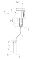
- Fig. 2 is a schematic diagram of a locking apparatus in accordance with one embodiment of the invention.
- a medical apparatus 10 of one embodiment includes a medical instrument 12, a control panel 14, and a display unit 16.
- the medical apparatus 10 is an ultrasonic diagnostic apparatus that uses ultrasound waves for ultrasound diagnosis of a target, and the medical instrument 12 is illustrated as a main body of the medical apparatus 10.
- the medical instrument 12 includes a beam former (not shown) for transmit-focusing ultrasonic signals transmitted through a probe 20 and receive-focusing ultrasonic signals received through the probe 20, a data creator (not shown) for creating frame data based on the signals output from the beam former, a processor (not shown) for generating a two-dimensional or three-dimensional internal image of a target based on the frame data, a storage (not shown) for storing data, and the like.
- the control panel 14 includes a plurality of manipulation keys (not shown) and the like to drive the medical apparatus 10 or select a certain function thereof, and is electrically connected to the medical instrument 12.
- the control panel 14 is located in front of the medical instrument 12 and is swivelly coupled to the medical instrument 12 via a locking apparatus 100 (see Fig. 2 ) to rotate in a right-left direction or in an up-down direction.
- the display unit 16 serves to display ultrasound images generated by the medical instrument 12, operation states of the ultrasonic diagnostic apparatus 10, preset information for operating the ultrasonic diagnostic apparatus 10, and the like.
- the display unit 16 is located on top of the medical instrument 12 and is coupled thereto via the locking apparatus 100 to rotate in the right-left direction or in the up-down direction.
- the locking apparatus 100 of one embodiment includes a stationary part 110, a rotating part 120, a locking part 130, and a fluid supply part 140.
- the stationary part 110 is provided to the medical instrument 12 (see Fig. 1 ).
- the stationary part 110 is disposed between the medical instrument 12 and a device 15 (see Fig. 1 ) , such as the control panel 14 (see Fig. 1 ) , the display unit 16 (see Fig. 1 ), or the like, and secured to the medical instrument 12.
- the stationary part 110 may have a disc shape.
- the rotating part 120 is rotatably provided to the stationary part 110.
- the rotating part 120 has a disc shape corresponding to the shape of the stationary part 110.
- the rotating part 120 is rotatably coupled at the center thereof to a rotational shaft (not shown) coupled to the center of the stationary part 110, and is separated a predetermined distance from the stationary part 110.
- the device 15 is coupled to the rotating part 120.
- the device 15 coupled the rotating part 120 may be provided to the medical instrument 12 to rotate in a rotating direction of the rotating part 120.
- the locking part 130 is provided to the stationary part 110 to restrict movement of the rotating part 120.
- the locking part 130 is made of a material capable of expanding and contracting, and has a space therein to receive a fluid.
- the locking part 130 is illustrated as being made of a rubber material and can be expanded or contracted by hydraulic pressure that is supplied into the locking part 130.
- the locking part 130 expands to compress the rotating part 120, movement of which is in turn restricted by friction between the rotating part 120 and the locking part 130, so that the rotation of the rotating device 120 and the device 15 coupled to the rotating device 120 is restricted.
- the fluid supply part 140 supplies a fluid to the locking part 130 so as to allow the locking part 130 to restrict the movement of the rotating part 120.
- the fluid supply part 140 includes a fluid supply passage 141 and a syringe unit 145.
- the fluid supply passage 141 communicates with the locking part 130.
- the fluid supply passage 141 is illustrated as including a tube member that is connected at one end thereof to the locking part 130 and at the other end thereof to the syringe unit 145.
- the fluid supply passage 141 connects the locking part 130 to the syringe unit 145, thereby providing a path through which the fluid flows from the syringe unit 145 to the locking part 130 or vice versa.
- the syringe unit 145 supplies the fluid to the locking part 130 or receives the fluid discharged therefrom through the fluid supply passage 141.
- the syringe unit 145 includes a cylinder 146, a piston unit 147, and a resilient member 148.
- the cylinder 146 serves to contain the fluid.
- An interior of the cylinder 146 is formed with a space for receiving the fluid, in which the space communicates with the fluid supply passage 141.
- the piston unit 147 is disposed inside the cylinder 146.
- the piston unit 147 reciprocates within the cylinder 146.
- the piston unit 147 serves to supply the fluid to the locking part 130 or discharge the fluid from the locking part 130 while reciprocating within the cylinder 146.
- the piston unit 147 pushes the fluid out of the cylinder 146 into the fluid supply passage 141 so that the fluid received in the cylinder 146 can be supplied to the locking part 130.
- the piston unit 147 forces the fluid supplied to the locking part 130 to be discharged therefrom.
- the piston unit 147 includes a piston 147a, a rod 147b, and a knob 147c.
- the piston 147a comes into close contact with an inner wall of the cylinder 146 to contact the fluid within the cylinder 146, and the knob 147c is located outside the cylinder 146 and connected to the piston 147a via the rod 147b.
- reciprocation of the piston unit 147 for allowing the fluid to be supplied to the locking part 130 or discharged therefrom is accomplished by operation of the knob 147c.
- the knob 147c may be manually operated by a user pulling the knob 147c.
- the knob 147c may be operated by power from an electric motor, such as a drive motor, a hydraulic or pneumatic cylinder, and the like, which is controlled by the medical instrument 12.
- the resilient member 148 serves to compress the piston unit 147 in a direction, in which the fluid is supplied.
- the resilient member 148 forces the piston unit 147 to move in the direction of supplying the fluid, so that movement of the rotating part 120 is restricted by the expanded locking part 130. That is, the rotating part 120 enters a locked stated.
- the resilient member 148 is provided to the cylinder 146 and the piston unit 147.
- the resilient member 148 is illustrated as a coil spring that is coupled at one side thereof to the cylinder 146 and at the other side thereof to the knob 147c of the piston unit 147.
- Fig. 3 shows operation of the locking apparatus shown in Fig. 2 .
- the locking part 130 With no external force applied to the syringe unit 145, that is, in a non-operative state of the knob 147c, the locking part 130 remains in an expanded state by hydraulic pressure of a fluid supplied from the fluid supply part 140, so that the rotating part 120 is locked by the locking part 130.
- the rotating part 120 locked by the locking part 130 With the rotating part 120 locked by the locking part 130, the rotating part 120 and the device 15 coupled to the rotating part 120 are suppressed from rotating due to friction between the rotating part 120 and the locking part 130.
- the rotating part 120 is released from the locked state and can be freely rotated, and the device 15 coupled to the rotating part 120 can also be freely rotated together with the rotating part 120.
- the locking apparatus 100 of the embodiment described above allows the locking part 130 to be expanded or contracted according to manipulation of a user so as to selectively restrict movement of the rotating part 120, so that the device 15 can be easily rotated without much effort or can be firmly secured according to the intention of the user, thereby providing satisfaction in manipulation of the device.
- the medical apparatus 10 including the locking apparatus 100 of the embodiment suppresses unintentional rotation of the device 15 by slight accidental impact, thereby preventing damage of the device 15, the medical instrument 12 and the like due to the unintentional rotation of the device and collision between the device 15 and the medical instrument 12 or other devices resulting therefrom.
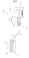
- Fig. 4 is a schematic diagram of a locking apparatus according to another embodiment, and Fig. 5 shows operation of the locking apparatus of Fig. 4 .
- a locking apparatus 200 of this embodiment includes a rotating part 220 that has a fixing groove 221 formed on one side thereof with.
- the fixing groove 221 is formed on the one side of the rotating part 220, that is, on a surface of the rotating part 220 which will be brought into contact with a locking part 130.
- the rotating part 220 has a plurality of fixing grooves 221 on the one side thereof.
- the plural fixing grooves 221 are arranged along a track with which the locking part 130 will be brought into contact during rotation of the rotating part 220.
- the number of fixing grooves 221 and a distance between the respective fixing grooves 221 may be adjusted by taking into account the minimum rotating angle of the rotating part 220 that allows the direction of the device 15 (see Fig. 1 ) to be efficiently adjusted.
- the expanded locking part 130 is inserted into one of the fixing grooves 221.
- the locking part 130 inserted into the fixing groove 221 interferes with the rotating part 220 to thereby restrict movement of the rotating part 220.
- the rotating part 220 locked by the locking part 130 With the rotating part 220 locked by the locking part 130, the rotating part 220 and the device 15 coupled to the rotating part 220 enter a locked state and are suppressed from rotation.
- the rotating part 220 is released from the locked state and can be freely rotated, and the device 15 coupled to the rotating part 220 can also be freely rotated together with the rotating part 220.
- the locking apparatus 200 of this embodiment can further reliably secure the device 15 via coupling between the locking part 130 and the fixing groove 220 when securing the device 15.
- the locking apparatus allows a locking part to be expanded or contracted according to manipulation of a user so as to selectively restrict movement of a rotating part, so that a device mounted on a medical apparatus via the locking apparatus can be easily rotated without much effort or can be firmly secured according to the intention of a user, thereby providing satisfaction in manipulation.
- the medical apparatus including the locking apparatus suppresses unintentional rotation of a device thereon by slight accidental impact, thereby preventing damage of the device, a medical instrument, and the like due to the unintentional rotation of the device and collision between the device and the medical instrument or other devices resulting therefrom.
Landscapes
- Engineering & Computer Science (AREA)
- Health & Medical Sciences (AREA)
- General Engineering & Computer Science (AREA)
- Life Sciences & Earth Sciences (AREA)
- Mechanical Engineering (AREA)
- Surgery (AREA)
- General Health & Medical Sciences (AREA)
- Biomedical Technology (AREA)
- Molecular Biology (AREA)
- Animal Behavior & Ethology (AREA)
- Heart & Thoracic Surgery (AREA)
- Public Health (AREA)
- Veterinary Medicine (AREA)
- Medical Informatics (AREA)
- Nuclear Medicine, Radiotherapy & Molecular Imaging (AREA)
- Pathology (AREA)
- Oral & Maxillofacial Surgery (AREA)
- Physics & Mathematics (AREA)
- Biophysics (AREA)
- Radiology & Medical Imaging (AREA)
- Infusion, Injection, And Reservoir Apparatuses (AREA)
- Ultra Sonic Daignosis Equipment (AREA)
Abstract
Description
- The present invention relates to a locking apparatus and a medical apparatus including the same. More particularly, the present invention relates to a locking apparatus and a medical apparatus including the same that can selectively restrict rotation of devices, such as a control panel, display unit, and the like.
- Generally, an ultrasonic diagnostic apparatus refers to a non-invasive apparatus that irradiates an ultrasound signal from a surface of a patient body towards a target internal organ beneath the body surface and obtains an image of a monolayer or blood flow in soft tissue from information in the reflected ultrasound signal (ultrasound echo-signal). The ultrasonic diagnostic apparatus has been widely used for diagnosis of the heart, the abdomen, the urinary organs, and in obstetrics and gynecology due to various merits thereof such as small size, low price, real-time image display, and high stability through elimination of radiation exposure, as compared with other image diagnostic systems, such as X-ray diagnostic systems, computerized tomography scanners (CT scanners), magnetic resonance imagers (MRIs), nuclear medicine diagnostic apparatuses, and the like.
- The ultrasonic diagnostic apparatus includes a cart-shaped main body for receiving main components of the diagnostic apparatus and a probe for transmitting and receiving ultrasound signals in association with the main body. Additionally, the diagnostic apparatus includes a control panel and a display unit mounted on the main body.
- The control panel is located in front of the main body and provided with various switches and keys for inputting commands for manipulation of the apparatus. The display unit is mounted on top of the main body and displays an image of an ultrasonic diagnosis result.
- The control panel and the display unit may be rotated in the right and left directions to improve user convenience. The control panel and the display unit are typically provided to the main body via swivel hinges.
- The swivel hinge is disposed between the control panel or the display unit and the main body and rotatably couples the control panel or the display unit thereto, so that the control panel or the display unit can be rotated to adjust the direction thereof as desired, even when the main body is securely mounted at a certain location.
- It should be noted that the above description is provided for understanding of the background of the invention and is not a description of a conventional technique well-known in the art.
- The swivel hinge is required to generate a proper degree of friction, that is, a proper maximum static friction torque, upon rotation of a device, such as the control panel or the display unit. For example, if the maximum static friction torque of the swivel hinge is too high, an excessive force will be required to rotate the device, and if the maximum static friction torque of the swivel hinge is too low, the device is liable to rotate even by slight impact, so that a user cannot obtain satisfaction in manipulation of the device.
- Since the maximum static friction torque of the swivel hinge is determined by several factors such as fastening force of the swivel hinge, elasticity of a spring, and the like, it is difficult to adjust the maximum static friction torque of the swivel hinge to a constant value. Moreover, since the preferred maximum static friction torques of the swivel hinges varies from user to user, the existing swivel hinges do not provide satisfaction in manipulation of the devices having the swivel hinges coupled thereto.
- Therefore, there is a need to solve such a problem.
- The present invention is conceived to solve the problem of the related art as described above, and an aspect of the invention is to provide a locking apparatus and a medical apparatus including the same that has improved structure to provide satisfaction in manipulation.
- In accordance with one aspect of the invention, a locking apparatus includes: a stationary part; a rotating part rotatably provided to the stationary part; a locking part provided to the stationary part to restrict rotation of the rotating part; and a fluid supply part providing a fluid to the locking part to allow the locking part to restrict the rotation of the rotating part.
- The locking part may be made of a rubber material.
- The fluid supply part may include a fluid supply passage communicating with the locking part; and a syringe unit supplying the fluid to the locking part or receiving the fluid discharged from the locking part through the fluid supply passage.
- The syringe unit may include a cylinder containing the fluid; and a piston unit reciprocating within the cylinder to supply the fluid to the locking part or to discharge the fluid from the locking part.
- The syringe unit may further include a resilient member compressing the piston unit in a direction of supplying the fluid to lock the rotating part.
- The resilient member may be provided to the cylinder and the piston unit.
- In accordance with another aspect, a medical apparatus includes the locking apparatus and a medical instrument provided to the locking apparatus.
- The above and other aspects, features and advantages of the invention will become apparent from the following description in conjunction with the accompanying drawings, in which:
- Fig. 1
- is a perspective view of a medical apparatus in accordance with one embodiment of the present invention;
- Fig. 2
- is a schematic diagram of a locking apparatus in accordance with one embodiment of the present invention;
- Fig. 3
- shows operation of the locking apparatus shown in
Fig. 2 ; - Fig. 4
- is a schematic diagram of a locking apparatus in accordance with another embodiment of the present invention; and
- Fig. 5
- shows operation of the locking apparatus shown in
Fig. 4 . - Embodiments of the invention will now be described in detail with reference to the accompanying drawings. It should be noted that the drawings are not to precise scale and may be exaggerated in thickness of lines or size of components for descriptive convenience and clarity only. Furthermore, terms used herein are defined by taking functions of the invention into account and can be changed according to the custom or intention of users or operators. Therefore, definition of the terms should be made according to overall disclosures set forth herein.
-
Fig. 1 is a perspective view of a medical apparatus in accordance with one embodiment of the invention, andFig. 2 is a schematic diagram of a locking apparatus in accordance with one embodiment of the invention. - Referring to
Fig. 1 , amedical apparatus 10 of one embodiment includes amedical instrument 12, acontrol panel 14, and a display unit 16. In this embodiment, themedical apparatus 10 is an ultrasonic diagnostic apparatus that uses ultrasound waves for ultrasound diagnosis of a target, and themedical instrument 12 is illustrated as a main body of themedical apparatus 10. - The
medical instrument 12 includes a beam former (not shown) for transmit-focusing ultrasonic signals transmitted through aprobe 20 and receive-focusing ultrasonic signals received through theprobe 20, a data creator (not shown) for creating frame data based on the signals output from the beam former, a processor (not shown) for generating a two-dimensional or three-dimensional internal image of a target based on the frame data, a storage (not shown) for storing data, and the like. - The
control panel 14 includes a plurality of manipulation keys (not shown) and the like to drive themedical apparatus 10 or select a certain function thereof, and is electrically connected to themedical instrument 12. Preferably, thecontrol panel 14 is located in front of themedical instrument 12 and is swivelly coupled to themedical instrument 12 via a locking apparatus 100 (seeFig. 2 ) to rotate in a right-left direction or in an up-down direction. - The display unit 16 serves to display ultrasound images generated by the
medical instrument 12, operation states of the ultrasonicdiagnostic apparatus 10, preset information for operating the ultrasonicdiagnostic apparatus 10, and the like. Preferably, the display unit 16 is located on top of themedical instrument 12 and is coupled thereto via thelocking apparatus 100 to rotate in the right-left direction or in the up-down direction. - Referring to
Fig. 2 , thelocking apparatus 100 of one embodiment includes astationary part 110, a rotatingpart 120, alocking part 130, and afluid supply part 140. - The
stationary part 110 is provided to the medical instrument 12 (seeFig. 1 ). Thestationary part 110 is disposed between themedical instrument 12 and a device 15 (seeFig. 1 ) , such as the control panel 14 (seeFig. 1 ) , the display unit 16 (seeFig. 1 ), or the like, and secured to themedical instrument 12. For example, thestationary part 110 may have a disc shape. - The rotating
part 120 is rotatably provided to thestationary part 110. For example, therotating part 120 has a disc shape corresponding to the shape of thestationary part 110. The rotatingpart 120 is rotatably coupled at the center thereof to a rotational shaft (not shown) coupled to the center of thestationary part 110, and is separated a predetermined distance from thestationary part 110. - The device 15 is coupled to the
rotating part 120. As such, the device 15 coupled the rotatingpart 120 may be provided to themedical instrument 12 to rotate in a rotating direction of therotating part 120. - The
locking part 130 is provided to thestationary part 110 to restrict movement of therotating part 120. The lockingpart 130 is made of a material capable of expanding and contracting, and has a space therein to receive a fluid. In this embodiment, the lockingpart 130 is illustrated as being made of a rubber material and can be expanded or contracted by hydraulic pressure that is supplied into the lockingpart 130. - When the hydraulic pressure increases inside the locking
part 130, the lockingpart 130 expands to compress therotating part 120, movement of which is in turn restricted by friction between therotating part 120 and the lockingpart 130, so that the rotation of therotating device 120 and the device 15 coupled to therotating device 120 is restricted. - The
fluid supply part 140 supplies a fluid to the lockingpart 130 so as to allow thelocking part 130 to restrict the movement of therotating part 120. Thefluid supply part 140 includes afluid supply passage 141 and asyringe unit 145. - The
fluid supply passage 141 communicates with the lockingpart 130. In this embodiment, thefluid supply passage 141 is illustrated as including a tube member that is connected at one end thereof to the lockingpart 130 and at the other end thereof to thesyringe unit 145. Thefluid supply passage 141 connects the lockingpart 130 to thesyringe unit 145, thereby providing a path through which the fluid flows from thesyringe unit 145 to the lockingpart 130 or vice versa. - The
syringe unit 145 supplies the fluid to the lockingpart 130 or receives the fluid discharged therefrom through thefluid supply passage 141. Thesyringe unit 145 includes acylinder 146, apiston unit 147, and aresilient member 148. - The
cylinder 146 serves to contain the fluid. An interior of thecylinder 146 is formed with a space for receiving the fluid, in which the space communicates with thefluid supply passage 141. - The
piston unit 147 is disposed inside thecylinder 146. Thepiston unit 147 reciprocates within thecylinder 146. Thepiston unit 147 serves to supply the fluid to the lockingpart 130 or discharge the fluid from the lockingpart 130 while reciprocating within thecylinder 146. - That is, when moving toward a side of the
cylinder 146 to which thefluid supply passage 141 is connected, thepiston unit 147 pushes the fluid out of thecylinder 146 into thefluid supply passage 141 so that the fluid received in thecylinder 146 can be supplied to the lockingpart 130. When moving in the opposite direction, thepiston unit 147 forces the fluid supplied to the lockingpart 130 to be discharged therefrom. - In this embodiment, the
piston unit 147 includes apiston 147a, arod 147b, and aknob 147c. Thepiston 147a comes into close contact with an inner wall of thecylinder 146 to contact the fluid within thecylinder 146, and theknob 147c is located outside thecylinder 146 and connected to thepiston 147a via therod 147b. - According to this embodiment, reciprocation of the
piston unit 147 for allowing the fluid to be supplied to the lockingpart 130 or discharged therefrom is accomplished by operation of theknob 147c. - In one example, the
knob 147c may be manually operated by a user pulling theknob 147c. In another example, theknob 147c may be operated by power from an electric motor, such as a drive motor, a hydraulic or pneumatic cylinder, and the like, which is controlled by themedical instrument 12. - The
resilient member 148 serves to compress thepiston unit 147 in a direction, in which the fluid is supplied. Theresilient member 148 forces thepiston unit 147 to move in the direction of supplying the fluid, so that movement of therotating part 120 is restricted by the expanded lockingpart 130. That is, therotating part 120 enters a locked stated. - The
resilient member 148 is provided to thecylinder 146 and thepiston unit 147. In this embodiment, theresilient member 148 is illustrated as a coil spring that is coupled at one side thereof to thecylinder 146 and at the other side thereof to theknob 147c of thepiston unit 147. -
Fig. 3 shows operation of the locking apparatus shown inFig. 2 . - Operation and effect of the locking apparatus and a medical apparatus including the same according to the embodiment will now be described with reference to
Figs. 2 and3 . - First, as shown in
Fig. 2 , with no external force applied to thesyringe unit 145, that is, in a non-operative state of theknob 147c, the lockingpart 130 remains in an expanded state by hydraulic pressure of a fluid supplied from thefluid supply part 140, so that therotating part 120 is locked by the lockingpart 130. - With the
rotating part 120 locked by the lockingpart 130, therotating part 120 and the device 15 coupled to therotating part 120 are suppressed from rotating due to friction between therotating part 120 and the lockingpart 130. - Then, as shown in
Fig. 3 , when theknob 147c is manipulated to move thepiston unit 147 in an opposite direction to a direction in which the fluid is supplied, the fluid received in the lockingpart 130 is discharged to thefluid supply passage 141, so that the volume of the lockingpart 130 is reduced. - As such, when the volume of the locking
part 130 is reduced to such a degree that the lockingpart 130 cannot compress therotating part 120, therotating part 120 is released from the locked state and can be freely rotated, and the device 15 coupled to therotating part 120 can also be freely rotated together with therotating part 120. - The
locking apparatus 100 of the embodiment described above allows the lockingpart 130 to be expanded or contracted according to manipulation of a user so as to selectively restrict movement of therotating part 120, so that the device 15 can be easily rotated without much effort or can be firmly secured according to the intention of the user, thereby providing satisfaction in manipulation of the device. - Further, the
medical apparatus 10 including thelocking apparatus 100 of the embodiment suppresses unintentional rotation of the device 15 by slight accidental impact, thereby preventing damage of the device 15, themedical instrument 12 and the like due to the unintentional rotation of the device and collision between the device 15 and themedical instrument 12 or other devices resulting therefrom. -
Fig. 4 is a schematic diagram of a locking apparatus according to another embodiment, andFig. 5 shows operation of the locking apparatus ofFig. 4 . - For descriptive convenience, the same or similar components of the embodiment as those of the above embodiment will be denoted by the same reference numerals, and a detailed description thereof will be omitted herein.
- First, referring to
Fig. 4 , alocking apparatus 200 of this embodiment includes arotating part 220 that has a fixinggroove 221 formed on one side thereof with. - The fixing
groove 221 is formed on the one side of therotating part 220, that is, on a surface of therotating part 220 which will be brought into contact with a lockingpart 130. In this embodiment, therotating part 220 has a plurality of fixinggrooves 221 on the one side thereof. Theplural fixing grooves 221 are arranged along a track with which thelocking part 130 will be brought into contact during rotation of therotating part 220. - Here, the number of fixing
grooves 221 and a distance between the respective fixinggrooves 221 may be adjusted by taking into account the minimum rotating angle of therotating part 220 that allows the direction of the device 15 (seeFig. 1 ) to be efficiently adjusted. - As shown in
Fig. 4 , the expanded lockingpart 130 is inserted into one of the fixinggrooves 221. The lockingpart 130 inserted into the fixinggroove 221 interferes with therotating part 220 to thereby restrict movement of therotating part 220. With therotating part 220 locked by the lockingpart 130, therotating part 220 and the device 15 coupled to therotating part 220 enter a locked state and are suppressed from rotation. - Then, as shown in
Fig. 5 , when aknob 147c is manipulated to move apiston unit 147 in an opposite direction to the direction in which the fluid is supplied, the fluid received in the lockingpart 130 is discharged to afluid supply passage 141, so that the volume of the lockingpart 130 is reduced. - As such, when the volume of the locking
part 130 is reduced to allow thelocking part 130 to be released from the fixinggroove 221, therotating part 220 is released from the locked state and can be freely rotated, and the device 15 coupled to therotating part 220 can also be freely rotated together with therotating part 220. - The
locking apparatus 200 of this embodiment can further reliably secure the device 15 via coupling between the lockingpart 130 and the fixinggroove 220 when securing the device 15. - As such, the locking apparatus according to the embodiments allows a locking part to be expanded or contracted according to manipulation of a user so as to selectively restrict movement of a rotating part, so that a device mounted on a medical apparatus via the locking apparatus can be easily rotated without much effort or can be firmly secured according to the intention of a user, thereby providing satisfaction in manipulation.
- Further, the medical apparatus including the locking apparatus according to the embodiments suppresses unintentional rotation of a device thereon by slight accidental impact, thereby preventing damage of the device, a medical instrument, and the like due to the unintentional rotation of the device and collision between the device and the medical instrument or other devices resulting therefrom.
- Although some embodiments have been provided to illustrate the invention in conjunction with the drawings, it will be apparent to those skilled in the art that the embodiments are given by way of illustration only, and that various modifications and equivalent embodiments can be made without departing from the spirit and scope of the invention. The scope of the invention should be limited only by the accompanying claims.
Claims (7)
- A locking apparatus (100; 200), characterized by comprising:a stationary part (110);a rotating part (120; 220) rotatably provided to the stationary part (110);a locking part (130) provided to the stationary part (110) to restrict rotation of the rotating part (120; 220); anda fluid supply part (140) providing a fluid to the locking part (130) to allow the locking part (130) to restrict the rotation of the rotating part (120; 220).
- The locking apparatus (100; 200) according to claim 1, characterized in that the locking part (130) is made of a rubber material.
- The locking apparatus (100; 200) according to claim 1, characterized in that the fluid supply part (140) comprises:a fluid supply passage (141) communicating with the locking part (130); anda syringe unit (145) supplying the fluid to the locking part (130) or receiving the fluid discharged from the locking part (130) through the fluid supply passage (141).
- The locking apparatus (100; 200) according to claim 3, characterized in that the syringe unit (145) comprises:a cylinder (146) containing the fluid; anda piston unit (147) reciprocating within the cylinder (146) to supply the fluid to the locking part (130) or to discharge the fluid from the locking part (130).
- The locking apparatus (100; 200) according to claim 4, characterized in that the syringe unit (145) further comprises a resilient member (148) compressing the piston unit (147) in a direction of supplying the fluid to lock the rotating part (120; 220).
- The locking apparatus (100; 200) according to claim 5, characterized in that the resilient member (148) is provided to the cylinder (146) and the piston unit (147).
- A medical apparatus (10), characterized by comprising:the locking apparatus (100; 200) according to any one of claims 1 to 6; anda medical instrument (12) provided to the locking part (130) of the locking apparatus (100; 200).
Applications Claiming Priority (1)
| Application Number | Priority Date | Filing Date | Title |
|---|---|---|---|
| KR1020090116863A KR101031013B1 (en) | 2009-11-30 | 2009-11-30 | Locking device and medical device having same |
Publications (2)
| Publication Number | Publication Date |
|---|---|
| EP2327368A1 true EP2327368A1 (en) | 2011-06-01 |
| EP2327368B1 EP2327368B1 (en) | 2014-07-23 |
Family
ID=43558346
Family Applications (1)
| Application Number | Title | Priority Date | Filing Date |
|---|---|---|---|
| EP10189403.8A Not-in-force EP2327368B1 (en) | 2009-11-30 | 2010-10-29 | Locking apparatus and medical apparatus including the same |
Country Status (4)
| Country | Link |
|---|---|
| US (1) | US20110194888A1 (en) |
| EP (1) | EP2327368B1 (en) |
| JP (1) | JP2011115577A (en) |
| KR (1) | KR101031013B1 (en) |
Cited By (1)
| Publication number | Priority date | Publication date | Assignee | Title |
|---|---|---|---|---|
| EP2859850A1 (en) * | 2013-10-14 | 2015-04-15 | Samsung Medison Co., Ltd. | Control panel for ultrasonic diagnostic apparatus |
Families Citing this family (2)
| Publication number | Priority date | Publication date | Assignee | Title |
|---|---|---|---|---|
| KR101646724B1 (en) * | 2012-11-19 | 2016-08-12 | 알피니언메디칼시스템 주식회사 | Articulating arm device, and ultrasonic medical device comprising same |
| KR102256089B1 (en) * | 2019-07-30 | 2021-05-24 | 국립암센터 | Apparatus for staining body fluid smear |
Citations (3)
| Publication number | Priority date | Publication date | Assignee | Title |
|---|---|---|---|---|
| GB799577A (en) * | 1953-11-28 | 1958-08-13 | Otto Hilger | Improvements in or relating to disk brakes for vehicles, in particular for motor vehicles |
| US6021607A (en) * | 1999-01-04 | 2000-02-08 | Angove; Garret | Automatic door closing device |
| US20050282673A1 (en) * | 2002-04-29 | 2005-12-22 | Stefan Knappe | Pivot bearing unit comprising a braking device |
Family Cites Families (14)
| Publication number | Priority date | Publication date | Assignee | Title |
|---|---|---|---|---|
| US2567895A (en) * | 1948-08-19 | 1951-09-11 | Rommer Jack Jay | Device for ejecting an opaque medium in the soft parts of the body for x-raying purposes |
| US3190679A (en) * | 1963-05-20 | 1965-06-22 | Frank P Lester | Hose connector |
| US3638973A (en) * | 1969-06-04 | 1972-02-01 | Charles Ellis Poletti | Joint means for use in work supporting arm |
| DE2048592A1 (en) * | 1970-06-25 | 1972-02-03 | Slick Tripod Co Ltd | Camera storage or mounting head |
| US4632669A (en) * | 1984-05-07 | 1986-12-30 | Plastic Specialties, Inc. | Pressure indicating medical injection gun |
| DE3628038A1 (en) * | 1985-08-19 | 1987-02-26 | Timothy Robert Miller | PIVOTING UNIT |
| US4993722A (en) * | 1988-12-07 | 1991-02-19 | Npc, Inc. | Apparatus and method for improved pipe to manhole sealing |
| DE4411616C2 (en) * | 1994-04-02 | 2003-04-17 | Alstom | Method for operating a turbomachine |
| KR100214951B1 (en) * | 1995-11-02 | 1999-08-02 | 정몽규 | Accelerator pedal locking device |
| CA2314758A1 (en) * | 2000-07-28 | 2002-01-28 | Tenet Medical Engineering Inc. | Releasable lockable re-positionable arm like support apparatus |
| US6780170B2 (en) * | 2002-05-15 | 2004-08-24 | Liebel-Flarsheim Company | Hydraulic remote for a medical fluid injector |
| US6648825B1 (en) * | 2002-05-23 | 2003-11-18 | Koninklijke Philips Electronics N.V. | Diagnostic ultrasound system cart with swiveling control panel |
| JP4833281B2 (en) * | 2005-05-25 | 2011-12-07 | シンセス ゲゼルシャフト ミット ベシュレンクテル ハフツング | Surgical or dental drive unit control work device |
| US7341017B2 (en) * | 2006-06-07 | 2008-03-11 | J&J Machine & Tool, Inc. | Hydraulically locked boat accessory mounting device |
-
2009
- 2009-11-30 KR KR1020090116863A patent/KR101031013B1/en active Active
-
2010
- 2010-10-29 EP EP10189403.8A patent/EP2327368B1/en not_active Not-in-force
- 2010-11-19 JP JP2010259255A patent/JP2011115577A/en active Pending
- 2010-11-24 US US12/953,817 patent/US20110194888A1/en not_active Abandoned
Patent Citations (3)
| Publication number | Priority date | Publication date | Assignee | Title |
|---|---|---|---|---|
| GB799577A (en) * | 1953-11-28 | 1958-08-13 | Otto Hilger | Improvements in or relating to disk brakes for vehicles, in particular for motor vehicles |
| US6021607A (en) * | 1999-01-04 | 2000-02-08 | Angove; Garret | Automatic door closing device |
| US20050282673A1 (en) * | 2002-04-29 | 2005-12-22 | Stefan Knappe | Pivot bearing unit comprising a braking device |
Cited By (1)
| Publication number | Priority date | Publication date | Assignee | Title |
|---|---|---|---|---|
| EP2859850A1 (en) * | 2013-10-14 | 2015-04-15 | Samsung Medison Co., Ltd. | Control panel for ultrasonic diagnostic apparatus |
Also Published As
| Publication number | Publication date |
|---|---|
| JP2011115577A (en) | 2011-06-16 |
| KR101031013B1 (en) | 2011-04-25 |
| EP2327368B1 (en) | 2014-07-23 |
| US20110194888A1 (en) | 2011-08-11 |
Similar Documents
| Publication | Publication Date | Title |
|---|---|---|
| US11857812B2 (en) | Ultrasound guided opening of blood-brain barrier | |
| EP2298175B1 (en) | Three-dimensional probe apparatus | |
| CN109219394B (en) | Wearable ultrasound system and method | |
| US9763643B2 (en) | Probe for ultrasonic diagnostic apparatus | |
| JP2023510742A (en) | Systems and methods for robot-assisted tissue disruption targeting based on pre-treatment MRI/CT scans | |
| US6171247B1 (en) | Underfluid catheter system and method having a rotatable multiplane transducer | |
| CN105073012B (en) | Time echo marker | |
| US9999403B2 (en) | Medical device | |
| DE102009043890A1 (en) | Ultrasonic probe for guidance procedures | |
| KR102862350B1 (en) | Ultrasound diagnostic apparatus, and control method for same | |
| US20230377219A1 (en) | Systems and methods for reconstruction and visualization of anatomical data | |
| KR20250129759A (en) | Histotripsy systems and methods | |
| EP2327368B1 (en) | Locking apparatus and medical apparatus including the same | |
| JP2026500209A (en) | Fluidics Cart and Degassing System for Histotripsy System and Method | |
| US20170209118A1 (en) | Ultrasonic imaging apparatus and method for controlling the same | |
| US20160014344A1 (en) | Imaging apparatus and control method thereof | |
| US10159463B2 (en) | Ultrasound probe | |
| CN110123372A (en) | Medical diagnostic imaging apparatus and x-ray bombardment control device | |
| KR102513474B1 (en) | Ultrasonic imaging device and moving unit applying the same | |
| KR100894307B1 (en) | Driving device for magnetic resonance elastic technique | |
| EP2294982A1 (en) | Probe of ultrasonic diagnostic apparatus and method of suppressing vibration thereof | |
| Gumprecht et al. | A new ultrasound imaging concept for laparoscopy in urology | |
| EP3449839A1 (en) | Ultrasonic probe | |
| Baskin | History of Thyroid Ultrasound | |
| Garra | Elastography as a clinical tool |
Legal Events
| Date | Code | Title | Description |
|---|---|---|---|
| PUAI | Public reference made under article 153(3) epc to a published international application that has entered the european phase |
Free format text: ORIGINAL CODE: 0009012 |
|
| AK | Designated contracting states |
Kind code of ref document: A1 Designated state(s): AL AT BE BG CH CY CZ DE DK EE ES FI FR GB GR HR HU IE IS IT LI LT LU LV MC MK MT NL NO PL PT RO RS SE SI SK SM TR |
|
| AX | Request for extension of the european patent |
Extension state: BA ME |
|
| 17P | Request for examination filed |
Effective date: 20111123 |
|
| 17Q | First examination report despatched |
Effective date: 20130221 |
|
| GRAP | Despatch of communication of intention to grant a patent |
Free format text: ORIGINAL CODE: EPIDOSNIGR1 |
|
| INTG | Intention to grant announced |
Effective date: 20140213 |
|
| RAP1 | Party data changed (applicant data changed or rights of an application transferred) |
Owner name: MEDISON CO., LTD. |
|
| GRAS | Grant fee paid |
Free format text: ORIGINAL CODE: EPIDOSNIGR3 |
|
| GRAA | (expected) grant |
Free format text: ORIGINAL CODE: 0009210 |
|
| AK | Designated contracting states |
Kind code of ref document: B1 Designated state(s): AL AT BE BG CH CY CZ DE DK EE ES FI FR GB GR HR HU IE IS IT LI LT LU LV MC MK MT NL NO PL PT RO RS SE SI SK SM TR |
|
| REG | Reference to a national code |
Ref country code: GB Ref legal event code: FG4D |
|
| REG | Reference to a national code |
Ref country code: CH Ref legal event code: EP |
|
| REG | Reference to a national code |
Ref country code: IE Ref legal event code: FG4D |
|
| REG | Reference to a national code |
Ref country code: AT Ref legal event code: REF Ref document number: 678400 Country of ref document: AT Kind code of ref document: T Effective date: 20140815 |
|
| REG | Reference to a national code |
Ref country code: DE Ref legal event code: R096 Ref document number: 602010017657 Country of ref document: DE Effective date: 20140904 |
|
| RAP2 | Party data changed (patent owner data changed or rights of a patent transferred) |
Owner name: SAMSUNG MEDISON CO., LTD. |
|
| REG | Reference to a national code |
Ref country code: NL Ref legal event code: T3 |
|
| REG | Reference to a national code |
Ref country code: AT Ref legal event code: MK05 Ref document number: 678400 Country of ref document: AT Kind code of ref document: T Effective date: 20140723 |
|
| REG | Reference to a national code |
Ref country code: LT Ref legal event code: MG4D |
|
| PG25 | Lapsed in a contracting state [announced via postgrant information from national office to epo] |
Ref country code: ES Free format text: LAPSE BECAUSE OF FAILURE TO SUBMIT A TRANSLATION OF THE DESCRIPTION OR TO PAY THE FEE WITHIN THE PRESCRIBED TIME-LIMIT Effective date: 20140723 Ref country code: BG Free format text: LAPSE BECAUSE OF FAILURE TO SUBMIT A TRANSLATION OF THE DESCRIPTION OR TO PAY THE FEE WITHIN THE PRESCRIBED TIME-LIMIT Effective date: 20141023 Ref country code: LT Free format text: LAPSE BECAUSE OF FAILURE TO SUBMIT A TRANSLATION OF THE DESCRIPTION OR TO PAY THE FEE WITHIN THE PRESCRIBED TIME-LIMIT Effective date: 20140723 Ref country code: PT Free format text: LAPSE BECAUSE OF FAILURE TO SUBMIT A TRANSLATION OF THE DESCRIPTION OR TO PAY THE FEE WITHIN THE PRESCRIBED TIME-LIMIT Effective date: 20141124 Ref country code: SE Free format text: LAPSE BECAUSE OF FAILURE TO SUBMIT A TRANSLATION OF THE DESCRIPTION OR TO PAY THE FEE WITHIN THE PRESCRIBED TIME-LIMIT Effective date: 20140723 Ref country code: GR Free format text: LAPSE BECAUSE OF FAILURE TO SUBMIT A TRANSLATION OF THE DESCRIPTION OR TO PAY THE FEE WITHIN THE PRESCRIBED TIME-LIMIT Effective date: 20141024 Ref country code: FI Free format text: LAPSE BECAUSE OF FAILURE TO SUBMIT A TRANSLATION OF THE DESCRIPTION OR TO PAY THE FEE WITHIN THE PRESCRIBED TIME-LIMIT Effective date: 20140723 Ref country code: NO Free format text: LAPSE BECAUSE OF FAILURE TO SUBMIT A TRANSLATION OF THE DESCRIPTION OR TO PAY THE FEE WITHIN THE PRESCRIBED TIME-LIMIT Effective date: 20141023 |
|
| PG25 | Lapsed in a contracting state [announced via postgrant information from national office to epo] |
Ref country code: HR Free format text: LAPSE BECAUSE OF FAILURE TO SUBMIT A TRANSLATION OF THE DESCRIPTION OR TO PAY THE FEE WITHIN THE PRESCRIBED TIME-LIMIT Effective date: 20140723 Ref country code: CY Free format text: LAPSE BECAUSE OF FAILURE TO SUBMIT A TRANSLATION OF THE DESCRIPTION OR TO PAY THE FEE WITHIN THE PRESCRIBED TIME-LIMIT Effective date: 20140723 Ref country code: IS Free format text: LAPSE BECAUSE OF FAILURE TO SUBMIT A TRANSLATION OF THE DESCRIPTION OR TO PAY THE FEE WITHIN THE PRESCRIBED TIME-LIMIT Effective date: 20141123 Ref country code: PL Free format text: LAPSE BECAUSE OF FAILURE TO SUBMIT A TRANSLATION OF THE DESCRIPTION OR TO PAY THE FEE WITHIN THE PRESCRIBED TIME-LIMIT Effective date: 20140723 Ref country code: RS Free format text: LAPSE BECAUSE OF FAILURE TO SUBMIT A TRANSLATION OF THE DESCRIPTION OR TO PAY THE FEE WITHIN THE PRESCRIBED TIME-LIMIT Effective date: 20140723 Ref country code: AT Free format text: LAPSE BECAUSE OF FAILURE TO SUBMIT A TRANSLATION OF THE DESCRIPTION OR TO PAY THE FEE WITHIN THE PRESCRIBED TIME-LIMIT Effective date: 20140723 Ref country code: LV Free format text: LAPSE BECAUSE OF FAILURE TO SUBMIT A TRANSLATION OF THE DESCRIPTION OR TO PAY THE FEE WITHIN THE PRESCRIBED TIME-LIMIT Effective date: 20140723 |
|
| REG | Reference to a national code |
Ref country code: NL Ref legal event code: TD Effective date: 20150225 |
|
| REG | Reference to a national code |
Ref country code: DE Ref legal event code: R097 Ref document number: 602010017657 Country of ref document: DE |
|
| PG25 | Lapsed in a contracting state [announced via postgrant information from national office to epo] |
Ref country code: DK Free format text: LAPSE BECAUSE OF FAILURE TO SUBMIT A TRANSLATION OF THE DESCRIPTION OR TO PAY THE FEE WITHIN THE PRESCRIBED TIME-LIMIT Effective date: 20140723 Ref country code: RO Free format text: LAPSE BECAUSE OF FAILURE TO SUBMIT A TRANSLATION OF THE DESCRIPTION OR TO PAY THE FEE WITHIN THE PRESCRIBED TIME-LIMIT Effective date: 20140723 Ref country code: SK Free format text: LAPSE BECAUSE OF FAILURE TO SUBMIT A TRANSLATION OF THE DESCRIPTION OR TO PAY THE FEE WITHIN THE PRESCRIBED TIME-LIMIT Effective date: 20140723 Ref country code: CZ Free format text: LAPSE BECAUSE OF FAILURE TO SUBMIT A TRANSLATION OF THE DESCRIPTION OR TO PAY THE FEE WITHIN THE PRESCRIBED TIME-LIMIT Effective date: 20140723 Ref country code: EE Free format text: LAPSE BECAUSE OF FAILURE TO SUBMIT A TRANSLATION OF THE DESCRIPTION OR TO PAY THE FEE WITHIN THE PRESCRIBED TIME-LIMIT Effective date: 20140723 |
|
| PG25 | Lapsed in a contracting state [announced via postgrant information from national office to epo] |
Ref country code: LU Free format text: LAPSE BECAUSE OF FAILURE TO SUBMIT A TRANSLATION OF THE DESCRIPTION OR TO PAY THE FEE WITHIN THE PRESCRIBED TIME-LIMIT Effective date: 20141029 Ref country code: MC Free format text: LAPSE BECAUSE OF FAILURE TO SUBMIT A TRANSLATION OF THE DESCRIPTION OR TO PAY THE FEE WITHIN THE PRESCRIBED TIME-LIMIT Effective date: 20140723 |
|
| PLBE | No opposition filed within time limit |
Free format text: ORIGINAL CODE: 0009261 |
|
| REG | Reference to a national code |
Ref country code: CH Ref legal event code: PL |
|
| STAA | Information on the status of an ep patent application or granted ep patent |
Free format text: STATUS: NO OPPOSITION FILED WITHIN TIME LIMIT |
|
| GBPC | Gb: european patent ceased through non-payment of renewal fee |
Effective date: 20141029 |
|
| PG25 | Lapsed in a contracting state [announced via postgrant information from national office to epo] |
Ref country code: BE Free format text: LAPSE BECAUSE OF NON-PAYMENT OF DUE FEES Effective date: 20141031 |
|
| 26N | No opposition filed |
Effective date: 20150424 |
|
| REG | Reference to a national code |
Ref country code: IE Ref legal event code: MM4A |
|
| PG25 | Lapsed in a contracting state [announced via postgrant information from national office to epo] |
Ref country code: LI Free format text: LAPSE BECAUSE OF NON-PAYMENT OF DUE FEES Effective date: 20141031 Ref country code: GB Free format text: LAPSE BECAUSE OF NON-PAYMENT OF DUE FEES Effective date: 20141029 Ref country code: CH Free format text: LAPSE BECAUSE OF NON-PAYMENT OF DUE FEES Effective date: 20141031 |
|
| REG | Reference to a national code |
Ref country code: FR Ref legal event code: PLFP Year of fee payment: 6 |
|
| PG25 | Lapsed in a contracting state [announced via postgrant information from national office to epo] |
Ref country code: IE Free format text: LAPSE BECAUSE OF NON-PAYMENT OF DUE FEES Effective date: 20141029 |
|
| PG25 | Lapsed in a contracting state [announced via postgrant information from national office to epo] |
Ref country code: SI Free format text: LAPSE BECAUSE OF FAILURE TO SUBMIT A TRANSLATION OF THE DESCRIPTION OR TO PAY THE FEE WITHIN THE PRESCRIBED TIME-LIMIT Effective date: 20140723 |
|
| PG25 | Lapsed in a contracting state [announced via postgrant information from national office to epo] |
Ref country code: SM Free format text: LAPSE BECAUSE OF FAILURE TO SUBMIT A TRANSLATION OF THE DESCRIPTION OR TO PAY THE FEE WITHIN THE PRESCRIBED TIME-LIMIT Effective date: 20140723 |
|
| PG25 | Lapsed in a contracting state [announced via postgrant information from national office to epo] |
Ref country code: MT Free format text: LAPSE BECAUSE OF FAILURE TO SUBMIT A TRANSLATION OF THE DESCRIPTION OR TO PAY THE FEE WITHIN THE PRESCRIBED TIME-LIMIT Effective date: 20140723 Ref country code: HU Free format text: LAPSE BECAUSE OF FAILURE TO SUBMIT A TRANSLATION OF THE DESCRIPTION OR TO PAY THE FEE WITHIN THE PRESCRIBED TIME-LIMIT; INVALID AB INITIO Effective date: 20101029 Ref country code: BE Free format text: LAPSE BECAUSE OF FAILURE TO SUBMIT A TRANSLATION OF THE DESCRIPTION OR TO PAY THE FEE WITHIN THE PRESCRIBED TIME-LIMIT Effective date: 20140723 Ref country code: TR Free format text: LAPSE BECAUSE OF FAILURE TO SUBMIT A TRANSLATION OF THE DESCRIPTION OR TO PAY THE FEE WITHIN THE PRESCRIBED TIME-LIMIT Effective date: 20140723 |
|
| REG | Reference to a national code |
Ref country code: FR Ref legal event code: PLFP Year of fee payment: 7 |
|
| REG | Reference to a national code |
Ref country code: FR Ref legal event code: PLFP Year of fee payment: 8 |
|
| PG25 | Lapsed in a contracting state [announced via postgrant information from national office to epo] |
Ref country code: MK Free format text: LAPSE BECAUSE OF FAILURE TO SUBMIT A TRANSLATION OF THE DESCRIPTION OR TO PAY THE FEE WITHIN THE PRESCRIBED TIME-LIMIT Effective date: 20140723 |
|
| REG | Reference to a national code |
Ref country code: FR Ref legal event code: PLFP Year of fee payment: 9 |
|
| PG25 | Lapsed in a contracting state [announced via postgrant information from national office to epo] |
Ref country code: AL Free format text: LAPSE BECAUSE OF FAILURE TO SUBMIT A TRANSLATION OF THE DESCRIPTION OR TO PAY THE FEE WITHIN THE PRESCRIBED TIME-LIMIT Effective date: 20140723 |
|
| PGFP | Annual fee paid to national office [announced via postgrant information from national office to epo] |
Ref country code: FR Payment date: 20180910 Year of fee payment: 9 |
|
| PGFP | Annual fee paid to national office [announced via postgrant information from national office to epo] |
Ref country code: NL Payment date: 20180906 Year of fee payment: 9 |
|
| PGFP | Annual fee paid to national office [announced via postgrant information from national office to epo] |
Ref country code: DE Payment date: 20180905 Year of fee payment: 9 |
|
| PGFP | Annual fee paid to national office [announced via postgrant information from national office to epo] |
Ref country code: IT Payment date: 20181012 Year of fee payment: 9 |
|
| REG | Reference to a national code |
Ref country code: DE Ref legal event code: R119 Ref document number: 602010017657 Country of ref document: DE |
|
| REG | Reference to a national code |
Ref country code: NL Ref legal event code: MM Effective date: 20191101 |
|
| PG25 | Lapsed in a contracting state [announced via postgrant information from national office to epo] |
Ref country code: DE Free format text: LAPSE BECAUSE OF NON-PAYMENT OF DUE FEES Effective date: 20200501 |
|
| PG25 | Lapsed in a contracting state [announced via postgrant information from national office to epo] |
Ref country code: NL Free format text: LAPSE BECAUSE OF NON-PAYMENT OF DUE FEES Effective date: 20191101 |
|
| PG25 | Lapsed in a contracting state [announced via postgrant information from national office to epo] |
Ref country code: IT Free format text: LAPSE BECAUSE OF NON-PAYMENT OF DUE FEES Effective date: 20191029 Ref country code: FR Free format text: LAPSE BECAUSE OF NON-PAYMENT OF DUE FEES Effective date: 20191031 |