EP2326580B1 - Dual apron seal - Google Patents
Dual apron seal Download PDFInfo
- Publication number
- EP2326580B1 EP2326580B1 EP09815322.4A EP09815322A EP2326580B1 EP 2326580 B1 EP2326580 B1 EP 2326580B1 EP 09815322 A EP09815322 A EP 09815322A EP 2326580 B1 EP2326580 B1 EP 2326580B1
- Authority
- EP
- European Patent Office
- Prior art keywords
- seal
- seal member
- conveyor belt
- orientation
- primary
- Prior art date
- Legal status (The legal status is an assumption and is not a legal conclusion. Google has not performed a legal analysis and makes no representation as to the accuracy of the status listed.)
- Active
Links
Images

Classifications
-
- F—MECHANICAL ENGINEERING; LIGHTING; HEATING; WEAPONS; BLASTING
- F16—ENGINEERING ELEMENTS AND UNITS; GENERAL MEASURES FOR PRODUCING AND MAINTAINING EFFECTIVE FUNCTIONING OF MACHINES OR INSTALLATIONS; THERMAL INSULATION IN GENERAL
- F16J—PISTONS; CYLINDERS; SEALINGS
- F16J15/00—Sealings
- F16J15/16—Sealings between relatively-moving surfaces
- F16J15/32—Sealings between relatively-moving surfaces with elastic sealings, e.g. O-rings
- F16J15/3204—Sealings between relatively-moving surfaces with elastic sealings, e.g. O-rings with at least one lip
- F16J15/3232—Sealings between relatively-moving surfaces with elastic sealings, e.g. O-rings with at least one lip having two or more lips
-
- B—PERFORMING OPERATIONS; TRANSPORTING
- B65—CONVEYING; PACKING; STORING; HANDLING THIN OR FILAMENTARY MATERIAL
- B65G—TRANSPORT OR STORAGE DEVICES, e.g. CONVEYORS FOR LOADING OR TIPPING, SHOP CONVEYOR SYSTEMS OR PNEUMATIC TUBE CONVEYORS
- B65G21/00—Supporting or protective framework or housings for endless load-carriers or traction elements of belt or chain conveyors
- B65G21/20—Means incorporated in, or attached to, framework or housings for guiding load-carriers, traction elements or loads supported on moving surfaces
- B65G21/2045—Mechanical means for guiding or retaining the load on the load-carrying surface
- B65G21/2063—Mechanical means for guiding or retaining the load on the load-carrying surface comprising elements not movable in the direction of load-transport
- B65G21/2072—Laterial guidance means
- B65G21/2081—Laterial guidance means for bulk material, e.g. skirts
-
- F—MECHANICAL ENGINEERING; LIGHTING; HEATING; WEAPONS; BLASTING
- F16—ENGINEERING ELEMENTS AND UNITS; GENERAL MEASURES FOR PRODUCING AND MAINTAINING EFFECTIVE FUNCTIONING OF MACHINES OR INSTALLATIONS; THERMAL INSULATION IN GENERAL
- F16J—PISTONS; CYLINDERS; SEALINGS
- F16J15/00—Sealings
- F16J15/16—Sealings between relatively-moving surfaces
- F16J15/32—Sealings between relatively-moving surfaces with elastic sealings, e.g. O-rings
- F16J15/3268—Mounting of sealing rings
-
- Y—GENERAL TAGGING OF NEW TECHNOLOGICAL DEVELOPMENTS; GENERAL TAGGING OF CROSS-SECTIONAL TECHNOLOGIES SPANNING OVER SEVERAL SECTIONS OF THE IPC; TECHNICAL SUBJECTS COVERED BY FORMER USPC CROSS-REFERENCE ART COLLECTIONS [XRACs] AND DIGESTS
- Y10—TECHNICAL SUBJECTS COVERED BY FORMER USPC
- Y10T—TECHNICAL SUBJECTS COVERED BY FORMER US CLASSIFICATION
- Y10T29/00—Metal working
- Y10T29/49—Method of mechanical manufacture
- Y10T29/49826—Assembling or joining
- Y10T29/49863—Assembling or joining with prestressing of part
Definitions
- the present invention pertains to bulk material conveyor belt systems. More particularly, the present invention pertains to seal members for preventing bulk material from migrating off of conveyor belts.
- barrier seal assemblies on bulk material conveyor belt systems. It is also known to provide such barrier seal assemblies with seal members that comprise a seal that is biased against the conveyor belt to preventing bulk material from migrating off of the conveyor belt.
- WO 2007/148989 A1 relates to a barrier seal assembly used in combination with a conveyor belt installation.
- EP 1205694 A2 which constitutes the closest prior art, pertains to a seal unit for mechanical members, and discloses a seal member being a monolithic homogeneous piece of material having opposite first and second halves and comprising first and second primary seals and first and second secondary seals, the first secondary seal being resiliently movable relative to the first primary seal, the second secondary seal being resiliently movable relative to the second primary seal, the first primary seal and the first secondary seal being part of the first half of the seal member, the second primary seal and the second secondary seal being part of the second half of the seal member.
- NL 68 683 C discloses an annular seal for a rotating shaft.
- a seal member for sealing a conveyor belt is a monolithic homogeneous piece of material having opposite first and second halves and comprises first and second primary seals and first and second secondary seals.
- the first secondary seal is resiliently movable relative to the first primary seal.
- the second secondary seal is resiliently movable relative to the second priinary seal.
- the first primary seal and the first secondary seal are part of the first half of the seal member.
- the second primary seal and the second secondary seal are part of the second half of the seal member.
- a method comprises accessing a conveyor belt system.
- the conveyor belt system comprises a conveyor belt and a barrier seal assembly.
- the barrier seal assembly comprises a seal member and a sealing clamp.
- the seal member comprises first and second primary seals and first and second secondary seals.
- the seal member is clamped via the sealing clamp to the barrier seal assembly in a first orientation relative to the conveyor belt.
- the first secondary seal is resiliently biased against the conveyor belt when the seal member is in the first orientation.
- the method further comprises unclamping the sealing clamp in a manner releasing the seal member from the barrier seal assembly.
- the method comprises rotating the seal member into a second orientation relative to the conveyor belt from the first orientation.
- the second secondary seal is resiliently biased against the conveyor belt when the seal member is in the second orientation.
- the first secondary seal is unengaged with the conveyor belt when the seal member is in the second orientation.
- the method comprises clamping the sealing member to the barrier seal assembly via the sealing clamp while the seal member is in the second orientation.
- a barrier seal assembly 110 of the present invention is incorporated in a conveyor system such as that described in U.S. Patent Application Serial No. 12/234,384 ("the '384 Application").
- Each barrier seal assembly 110 includes a seal member 112, and a sealing clamp 114.
- the seal member 112 may be made of rubber, polyurethane or other similar materials.
- the seal is of EPDM and preferably has a durometer hardness of 70 (Shore D).
- the seal member 112 is adapted to replace the seal 64 of the '384 Application.
- the sealing clamp 114 is preferably the same as the sealing clamp 66. disclosed in the '384 Application.
- the sealing clamp 114 clamps the seal member 112 against a wear liner 116 directly above a conveyor belt 118.
- the wear liner 116 is the same as the wear liner 32 disclosed in the '384 Application.
- the seal member 112 is formed of a single unitary extrusion.
- Each seal member 112 comprises first and second primary seals 120a, 120b and first and second secondary seals 122a, 122b.
- the primary seal 120a or 120b presses against the belt 118 to contain material passing under the wear liner 116.
- the secondary seal 122a or 122b is resiliently urged against the belt 118 to contain fines that pass under the primary seal in order to redirect them back into the belt.
- the seal member 112 is positioned so that the first primary seal 120a and the first secondary seal 122a are in a sealing position, and the second primary seal 120b and the second secondary seal 122b are in a reserve position.
- the seal member 112 is positioned such that the first primary seal 120a and the first secondary seal 122a are adjacent the belt 118, and the second primary seal 120b and the second secondary seal 122b are upward and away from the belt. Because of the cross-sectional shape of the seal member 112, the second secondary seal 122b is deflected inward by the wear liner 116 and does not interfere with the securement of the seal member between the wear liner and sealing clamp 114. Fig.
- the cross-sectional shape of the seal member 112 is such that rotating the seal member 180° about a horizontal axis parallel to the seal member (e.g., the longitudinal axis x of the seal member) orients the second primary seal 120b and the second secondary seal 122b in the sealing position and orients the first primary seal 120a and the first secondary seal 122a in the reserve position.
- the cross-sectional shape of the seal member 112 is such that the shape and orientation of the first primary seal 120a when the first primary seal is in its sealing position is at least substantially the same as the shape and orientation of the second primary seal 120b when the second primary seal is in its sealing position.
- the cross-sectional shape of the seal member 112 is preferably such that the shape and orientation of the first secondary seal 122a when the first secondary seal is in its sealing position is at least substantially the same as the shape and orientation of the second secondary seal 122b when the second secondary seal is in its sealing position.
- first primary seal 120a and first secondary seal 122a wear, a user progressively moves the seal member 112 downward to maintain the desired position of the first primary and secondary seals relative to the belt 118, until the first primary and secondary seals are so worn that they are not suitably effective. Then, the seal member 112 is released from the sealing clamp 114, rotated 180° about the horizontal axis x, and then re-clamped by the sealing clamp such that the second primary seal 120b and the second secondary seal 122b are in their sealing positions.
- the cross sectional shape of an alternative seal member (not shown) of the present invention is symmetrical about a longitudinal horizontal plane, as viewed when the alternative seal member is oriented like the seal member 112 of Fig. 1 .
- the alternative seal member it is insufficient to rotate the seal member about a horizontal axis parallel to the seal member. Instead, a user may rotate the seal member about a longitudinal axis of the seal member and switch the left and right seal members (assuming the conveyor system has seal members on the opposite sides of the conveyor belt) so that the second primary seal and second secondary seal of the alternative seal member is properly oriented in sealing positions.
- the user may rotate the seal member 180° about an axis perpendicular to the longitudinal axis of the seal member, or any other sequence of movements that result in the same final position.
Landscapes
- Engineering & Computer Science (AREA)
- General Engineering & Computer Science (AREA)
- Mechanical Engineering (AREA)
- Belt Conveyors (AREA)
- Structure Of Belt Conveyors (AREA)
- Sealing Devices (AREA)
Description
- The present invention pertains to bulk material conveyor belt systems. More particularly, the present invention pertains to seal members for preventing bulk material from migrating off of conveyor belts.
- It is known to provide barrier seal assemblies on bulk material conveyor belt systems. It is also known to provide such barrier seal assemblies with seal members that comprise a seal that is biased against the conveyor belt to preventing bulk material from migrating off of the conveyor belt.
-
WO 2007/148989 A1 relates to a barrier seal assembly used in combination with a conveyor belt installation. -
EP 1205694 A2 , which constitutes the closest prior art, pertains to a seal unit for mechanical members, and discloses a seal member being a monolithic homogeneous piece of material having opposite first and second halves and comprising first and second primary seals and first and second secondary seals, the first secondary seal being resiliently movable relative to the first primary seal, the second secondary seal being resiliently movable relative to the second primary seal, the first primary seal and the first secondary seal being part of the first half of the seal member, the second primary seal and the second secondary seal being part of the second half of the seal member.NL 68 683 C - In a first aspect of the invention, a seal member for sealing a conveyor belt is a monolithic homogeneous piece of material having opposite first and second halves and comprises first and second primary seals and first and second secondary seals. The first secondary seal is resiliently movable relative to the first primary seal. The second secondary seal is resiliently movable relative to the second priinary seal. The first primary seal and the first secondary seal are part of the first half of the seal member. The second primary seal and the second secondary seal are part of the second half of the seal member. When the seals on one of the first and second halves of the seal member become excessively worn, the seal member can be flipped so that the seals on the other half of the seal member can be utilized.
- In another aspect of the invention, a method comprises accessing a conveyor belt system. The conveyor belt system comprises a conveyor belt and a barrier seal assembly. The barrier seal assembly comprises a seal member and a sealing clamp. The seal member comprises first and second primary seals and first and second secondary seals. The seal member is clamped via the sealing clamp to the barrier seal assembly in a first orientation relative to the conveyor belt. The first secondary seal is resiliently biased against the conveyor belt when the seal member is in the first orientation. The method further comprises unclamping the sealing clamp in a manner releasing the seal member from the barrier seal assembly. Furthermore, the method comprises rotating the seal member into a second orientation relative to the conveyor belt from the first orientation. The second secondary seal is resiliently biased against the conveyor belt when the seal member is in the second orientation. The first secondary seal is unengaged with the conveyor belt when the seal member is in the second orientation. Still further, the method comprises clamping the sealing member to the barrier seal assembly via the sealing clamp while the seal member is in the second orientation.
- Further features and advantages of the present invention, as well as the structure and operation of various embodiments of the present invention, are described in detail below with reference to the accompanying drawings.
-
-
Fig. 1 is an enlarged fragmented, cross-sectional view of a barrier seal assembly having a seal member positioned adjacent a belt of a bulk material conveyor system. -
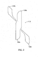
Fig. 2 is a cross-sectional view of the seal member ofFig. 1 with the seal member being in an unflexed state. - Reference numerals in the written specification and in the drawing figures indicate corresponding items.
- A
barrier seal assembly 110 of the present invention is incorporated in a conveyor system such as that described inU.S. Patent Application Serial No. 12/234,384 ("the '384 Application"). - Each
barrier seal assembly 110 includes aseal member 112, and asealing clamp 114. Theseal member 112 may be made of rubber, polyurethane or other similar materials. Preferably, the seal is of EPDM and preferably has a durometer hardness of 70 (Shore D). Theseal member 112 is adapted to replace the seal 64 of the '384 Application. The sealingclamp 114 is preferably the same as the sealing clamp 66. disclosed in the '384 Application. The sealingclamp 114 clamps theseal member 112 against awear liner 116 directly above aconveyor belt 118. Preferably, thewear liner 116 is the same as the wear liner 32 disclosed in the '384 Application. Preferably, theseal member 112 is formed of a single unitary extrusion. Eachseal member 112 comprises first and secondprimary seals secondary seals primary seal belt 118 to contain material passing under thewear liner 116. Thesecondary seal belt 118 to contain fines that pass under the primary seal in order to redirect them back into the belt. - As shown in
Fig. 1 , theseal member 112 is positioned so that the firstprimary seal 120a and the firstsecondary seal 122a are in a sealing position, and the secondprimary seal 120b and the secondsecondary seal 122b are in a reserve position. In particular, theseal member 112 is positioned such that the firstprimary seal 120a and the firstsecondary seal 122a are adjacent thebelt 118, and the secondprimary seal 120b and the secondsecondary seal 122b are upward and away from the belt. Because of the cross-sectional shape of theseal member 112, the secondsecondary seal 122b is deflected inward by thewear liner 116 and does not interfere with the securement of the seal member between the wear liner andsealing clamp 114.Fig. 2 shows theseal member 112 with thesecondary seals seal member 112 is such that rotating the seal member 180° about a horizontal axis parallel to the seal member (e.g., the longitudinal axis x of the seal member) orients the secondprimary seal 120b and the secondsecondary seal 122b in the sealing position and orients the firstprimary seal 120a and the firstsecondary seal 122a in the reserve position. Preferably, the cross-sectional shape of theseal member 112 is such that the shape and orientation of the firstprimary seal 120a when the first primary seal is in its sealing position is at least substantially the same as the shape and orientation of the secondprimary seal 120b when the second primary seal is in its sealing position. Likewise, the cross-sectional shape of theseal member 112 is preferably such that the shape and orientation of the firstsecondary seal 122a when the first secondary seal is in its sealing position is at least substantially the same as the shape and orientation of the secondsecondary seal 122b when the second secondary seal is in its sealing position. - In operation, as the first
primary seal 120a and firstsecondary seal 122a wear, a user progressively moves theseal member 112 downward to maintain the desired position of the first primary and secondary seals relative to thebelt 118, until the first primary and secondary seals are so worn that they are not suitably effective. Then, theseal member 112 is released from the sealingclamp 114, rotated 180° about the horizontal axis x, and then re-clamped by the sealing clamp such that the secondprimary seal 120b and the secondsecondary seal 122b are in their sealing positions. - The cross sectional shape of an alternative seal member (not shown) of the present invention is symmetrical about a longitudinal horizontal plane, as viewed when the alternative seal member is oriented like the
seal member 112 ofFig. 1 . With the alternative seal member, it is insufficient to rotate the seal member about a horizontal axis parallel to the seal member. Instead, a user may rotate the seal member about a longitudinal axis of the seal member and switch the left and right seal members (assuming the conveyor system has seal members on the opposite sides of the conveyor belt) so that the second primary seal and second secondary seal of the alternative seal member is properly oriented in sealing positions. If the user desires to move the alternative seal member so that the second primary seal and second secondary seal are in their sealing positions with the seal member without moving the seal member to the opposite side of the belt, the user may rotate the seal member 180° about an axis perpendicular to the longitudinal axis of the seal member, or any other sequence of movements that result in the same final position. - In view of the foregoing, it should be appreciated that the invention achieves the several advantages over prior art seal members.
- As various modifications could be made in the constructions and methods herein described and illustrated without departing from the scope of the invention, it is intended that all matter contained in the foregoing description or shown in the accompanying drawings shall be interpreted as illustrative rather than limiting. Thus, the breadth and scope of the present invention should not be limited by any of the above-described exemplary embodiments, but should be defined only in accordance with the following claims appended hereto.
Claims (8)
- A conveyor belt system, the conveyor belt system comprising a conveyor belt (118) and a barrier seal assembly (110), the barrier seal assembly (110) comprising a seal member (112) and a sealing clamp (114), wherein the seal member (112) is a monolithic homogeneous piece of material having opposite first and second halves and comprises first (120a) and second (120b) primary seals and first (122a) and second (122b) secondary seals, the first secondary seal (122a) is resiliently movable relative to the first primary seal (120a), the second secondary seal (122b) is resiliently movable relative to the second primary seal (120b), the first primary seal and the first secondary seal are part of the first half of the seal member (112), the second primary seal and the second secondary seal are part of the second half of the seal member (112), the first primary seal and the first secondary seal are adjustable between collapsed and expanded configurations, the first primary seal (120a) and the first secondary seal (122a) are closer to each other in the collapsed configuration, the second primary seal (120b) and the second secondary seal (122b) are adjustable between collapsed and expanded configurations, the second primary seal and the second secondary seal are closer to each other in the collapsed configuration, the seal member (112) is clamped to the barrier seal assembly (110) via the sealing clamp (114) in a manner such that the first secondary seal (122a) is resiliently biased against the conveyor belt (118) and such that the second secondary seal (122b) is unengaged with the conveyor belt (118) and is in its collapsed configuration.
- A conveyor belt system in accordance with claim 1 wherein the barrier seal assembly (110) further comprises a wear liner (116) and the seal member (112) is clamped against the wear liner via the sealing clamp (114).
- A conveyor belt system in accordance with claim 2 wherein the first half of the seal member (112) is symmetric to the second half of the seal member.
- A conveyor belt system in accordance with claim 3 wherein the first half of the seal member (112) is symmetric to the second half of the seal member about an axis.
- A method comprising:accessing a conveyor belt system according to any one of the previous claims;unclamping the sealing clamp (114) in a manner releasing the seal member (112) from the barrier seal assembly (110);rotating the seal member (112) into a second orientation, relative to the conveyor belt (118) from the first orientation, the second secondary seal (122b) being resiliently biased against the conveyor belt (118) when the seal member is in the second orientation, the first secondary seal (122a) being unengaged with the conveyor belt when the seal member is in the second orientation, the first primary seal (120a) and the first secondary seal (122a) being in the collapsed configuration when the seal member (112) is in the second orientation; andclamping the seal member (112) to the barrier seal assembly (110) via the sealing clamp (114) while the seal member is in the second orientation.
- A method in accordance with claim 5 wherein the seal member (112) is rotated one hundred and eighty degrees relative to the conveyor belt (118) during the step of rotating the seal member (112) into the second orientation from the first orientation.
- A method in accordance with claim 6 wherein the seal member (112) is rotated one hundred and eighty degrees about an axis (X) that is parallel to the conveyor belt (118) during the step of rotating the seal member (112) into the second orientation from the first orientation.
- A method in accordance with claim 5 wherein the barrier seal assembly (110) comprises a wear liner (116) and the seal member is biased against the wear liner via the sealing clamp (114) when the sealing member is clamped in the first orientation and when the sealing member (112) is clamped in the second orientation.
Priority Applications (1)
| Application Number | Priority Date | Filing Date | Title |
|---|---|---|---|
| PL09815322T PL2326580T3 (en) | 2008-09-22 | 2009-09-21 | Dual apron seal |
Applications Claiming Priority (2)
| Application Number | Priority Date | Filing Date | Title |
|---|---|---|---|
| US9906608P | 2008-09-22 | 2008-09-22 | |
| PCT/US2009/057654 WO2010033898A1 (en) | 2008-09-22 | 2009-09-21 | Dual apron seal |
Publications (3)
| Publication Number | Publication Date |
|---|---|
| EP2326580A1 EP2326580A1 (en) | 2011-06-01 |
| EP2326580A4 EP2326580A4 (en) | 2013-10-16 |
| EP2326580B1 true EP2326580B1 (en) | 2015-07-29 |
Family
ID=42036508
Family Applications (1)
| Application Number | Title | Priority Date | Filing Date |
|---|---|---|---|
| EP09815322.4A Active EP2326580B1 (en) | 2008-09-22 | 2009-09-21 | Dual apron seal |
Country Status (15)
| Country | Link |
|---|---|
| US (1) | US8172076B2 (en) |
| EP (1) | EP2326580B1 (en) |
| CN (1) | CN102131721B (en) |
| AR (1) | AR073626A1 (en) |
| AU (1) | AU2009293039B2 (en) |
| BR (1) | BRPI0914189B1 (en) |
| CA (1) | CA2731702C (en) |
| CL (1) | CL2011000578A1 (en) |
| ES (1) | ES2549906T3 (en) |
| MX (1) | MX345537B (en) |
| PE (1) | PE20110883A1 (en) |
| PL (1) | PL2326580T3 (en) |
| TW (1) | TWI518272B (en) |
| WO (1) | WO2010033898A1 (en) |
| ZA (1) | ZA201100441B (en) |
Families Citing this family (7)
| Publication number | Priority date | Publication date | Assignee | Title |
|---|---|---|---|---|
| US7980377B2 (en) * | 2009-08-19 | 2011-07-19 | Brelko Patents (Pty) Ltd. | Mounting arrangement |
| US8800756B2 (en) * | 2012-08-22 | 2014-08-12 | Benetech, Inc. | Externally adjustable internal wearliner for a material conveyor system |
| US9938087B2 (en) * | 2016-03-03 | 2018-04-10 | David K. Liland | Conveyor tail system |
| USD844895S1 (en) | 2017-08-21 | 2019-04-02 | Colgate-Palmolive Company | Soap bar |
| BE1027791B1 (en) * | 2019-11-06 | 2021-06-22 | Technic Gum International Polymeres Sprl | SEALING MUD |
| US12214309B2 (en) | 2021-04-06 | 2025-02-04 | Benetech, Inc. | Passive dust filter for an inspection hatch |
| US11919719B2 (en) | 2021-05-13 | 2024-03-05 | Benetech, Inc. | Drop and slide out idler assembly |
Family Cites Families (24)
| Publication number | Priority date | Publication date | Assignee | Title |
|---|---|---|---|---|
| US2685958A (en) * | 1954-08-10 | Wiper for wear strips of endless | ||
| NL68683C (en) * | ||||
| US3024893A (en) * | 1959-12-18 | 1962-03-13 | Max S Lambert | Skirtboard and sealer for conveyor systems |
| US3344909A (en) * | 1965-09-08 | 1967-10-03 | Sargents Sons Corp C G | Conveyor seals |
| US3499523A (en) * | 1968-05-20 | 1970-03-10 | Hardeman Lee Clegg | Conveyor belt skirt board |
| US4231471A (en) * | 1979-04-13 | 1980-11-04 | Gordon James R | Conveyor skirtboard apron |
| GB2087337B (en) * | 1980-11-11 | 1984-09-12 | Orbis Engineering Ltd | Side seal clamping menas for belt conveyors |
| US4641745A (en) * | 1985-06-24 | 1987-02-10 | Kansas City Rubber And Belting Company | Adjustable skirt holder for conveyor |
| US5016747A (en) | 1988-08-01 | 1991-05-21 | Martin Engineering Company | Barrier seal for conveyor skirtboard |
| WO1991013821A1 (en) * | 1990-03-07 | 1991-09-19 | Asgco Manufacturing, Inc. | Skirtboard system for conveyors |
| US5048669A (en) * | 1990-03-13 | 1991-09-17 | Martin Engineering Company | Modular conveyor belt sealing system |
| US4989727A (en) * | 1990-05-04 | 1991-02-05 | Gordon Belt Scrapers, Inc. | Skirtboard apron for a belt conveyor |
| ZA939109B (en) * | 1992-11-04 | 1994-08-22 | Brelko Patents Pty Ltd | Belt conveyor skirt seal arrangement |
| US5628392A (en) * | 1995-04-17 | 1997-05-13 | Richwood Industries, Inc. | Reversible belt scraper blade for cleaning high speed conveyor belts |
| US5816388A (en) * | 1997-05-05 | 1998-10-06 | Bowman; Houston R. | Pressure arm for floating skirt in conveyor |
| IT1319093B1 (en) * | 2000-11-09 | 2003-09-23 | Rft Spa | SEALING UNIT FOR RELATIVELY ROTATING MECHANICAL BODIES, IN PARTICULAR FOR FOUNDRY ROLLERS |
| US6547062B2 (en) * | 2001-05-08 | 2003-04-15 | Argonics, Inc. | Clamping system for a sealing element on a conveyor system, and a method of maintaining a sealing element on a conveyor system |
| US6575294B1 (en) * | 2002-07-11 | 2003-06-10 | Martin Engineering Company | Conveyor belt skirt assembly |
| US7789220B2 (en) * | 2005-11-11 | 2010-09-07 | Wear Applications & Management Services Pty Ltd | Liner plate replacement |
| FR2900915B1 (en) * | 2006-05-10 | 2008-12-26 | Financ De Gestion Soc Civ Ile | SEALING BUTTON FOR CONVEYOR |
| NO327021B1 (en) | 2006-06-22 | 2009-04-06 | Techno Track As | A barrier |
| US7571802B2 (en) * | 2007-07-26 | 2009-08-11 | Martin Engineering Company | Conveyor belt skirt assembly |
| US7484617B1 (en) * | 2007-11-30 | 2009-02-03 | Argonics, Inc. | Sealing system for conveying belt |
| US8006830B2 (en) * | 2008-09-19 | 2011-08-30 | Martin Engineering Company | Exteriorly mounted wear liner for bulk material conveyor belt systems |
-
2009
- 2009-09-21 AU AU2009293039A patent/AU2009293039B2/en active Active
- 2009-09-21 BR BRPI0914189-8A patent/BRPI0914189B1/en active IP Right Grant
- 2009-09-21 TW TW098131838A patent/TWI518272B/en active
- 2009-09-21 PE PE2011000612A patent/PE20110883A1/en active IP Right Grant
- 2009-09-21 ES ES09815322.4T patent/ES2549906T3/en active Active
- 2009-09-21 AR ARP090103619A patent/AR073626A1/en not_active Application Discontinuation
- 2009-09-21 EP EP09815322.4A patent/EP2326580B1/en active Active
- 2009-09-21 PL PL09815322T patent/PL2326580T3/en unknown
- 2009-09-21 CN CN2009801329121A patent/CN102131721B/en active Active
- 2009-09-21 CA CA2731702A patent/CA2731702C/en active Active
- 2009-09-21 US US12/563,663 patent/US8172076B2/en active Active
- 2009-09-21 WO PCT/US2009/057654 patent/WO2010033898A1/en not_active Ceased
- 2009-09-21 MX MX2011003018A patent/MX345537B/en active IP Right Grant
-
2011
- 2011-01-17 ZA ZA2011/00441A patent/ZA201100441B/en unknown
- 2011-03-18 CL CL2011000578A patent/CL2011000578A1/en unknown
Also Published As
| Publication number | Publication date |
|---|---|
| BRPI0914189B1 (en) | 2021-11-30 |
| US8172076B2 (en) | 2012-05-08 |
| AR073626A1 (en) | 2010-11-17 |
| WO2010033898A1 (en) | 2010-03-25 |
| CA2731702A1 (en) | 2010-03-25 |
| CA2731702C (en) | 2015-11-17 |
| CN102131721A (en) | 2011-07-20 |
| ZA201100441B (en) | 2013-04-24 |
| US20100072035A1 (en) | 2010-03-25 |
| TWI518272B (en) | 2016-01-21 |
| PE20110883A1 (en) | 2011-12-19 |
| ES2549906T3 (en) | 2015-11-03 |
| CL2011000578A1 (en) | 2011-08-26 |
| EP2326580A1 (en) | 2011-06-01 |
| MX2011003018A (en) | 2011-04-21 |
| EP2326580A4 (en) | 2013-10-16 |
| AU2009293039A1 (en) | 2010-03-25 |
| PL2326580T3 (en) | 2016-01-29 |
| AU2009293039B2 (en) | 2012-07-26 |
| CN102131721B (en) | 2013-08-28 |
| BRPI0914189A2 (en) | 2015-11-03 |
| TW201020427A (en) | 2010-06-01 |
| MX345537B (en) | 2017-02-03 |
Similar Documents
| Publication | Publication Date | Title |
|---|---|---|
| AU2009293039B2 (en) | Dual apron seal | |
| EP2065617B1 (en) | Vibration-proof structure | |
| CA2153128A1 (en) | System utilizing built-in redundancy switchover control | |
| AU3260697A (en) | Structural member | |
| CA2308611A1 (en) | A method of cutting/scoring adjacent flat elements and system for performing the method | |
| AU5730390A (en) | Flat top conveyor | |
| AU3913489A (en) | Impact modified polyurethane blends | |
| CA2077054A1 (en) | Fabric reinforced stiffener for air springs | |
| SI1070217T1 (en) | Arrangement for connecting the edges of two strips, for instance of a locking ring or band | |
| AU2002360707A1 (en) | Components, systems and methods for forming a gasketless seal between components in an ultrahigh pressure system | |
| AU2006267143B2 (en) | Fastening spider and method of fastening | |
| NL8400209A (en) | SEAL. | |
| US10953478B2 (en) | Collet comprising a seal | |
| US5958570A (en) | Laminated composite body, in particular conveyor belt | |
| MY126505A (en) | Specially shaped multilayer armour | |
| AU2008262654B2 (en) | Dust sealing | |
| EP0974358A3 (en) | Orally-administrable therapeutic and/or prophylactic agent for HTLV-1-related diseases | |
| EP1328767A1 (en) | Ceramic tile armour | |
| US20050189721A1 (en) | Seal arrangement | |
| CN102976044B (en) | Height adjusting assembly of transmission belt system | |
| WO2007042031A3 (en) | A panel element and a method of manufacturing a panel element | |
| WO2023161528A8 (en) | A CONJUGATE COMPRISING AT LEAST A ß-GLUCAN | |
| RU97107142A (en) | REINFORCED ELASTOMERIC SUPPORT FOR ENGINEERING STRUCTURES | |
| GB2346181A (en) | A belows member incorporating an elongate resilient member | |
| CA2258255A1 (en) | Structural member |
Legal Events
| Date | Code | Title | Description |
|---|---|---|---|
| PUAI | Public reference made under article 153(3) epc to a published international application that has entered the european phase |
Free format text: ORIGINAL CODE: 0009012 |
|
| 17P | Request for examination filed |
Effective date: 20110321 |
|
| AK | Designated contracting states |
Kind code of ref document: A1 Designated state(s): AT BE BG CH CY CZ DE DK EE ES FI FR GB GR HR HU IE IS IT LI LT LU LV MC MK MT NL NO PL PT RO SE SI SK SM TR |
|
| AX | Request for extension of the european patent |
Extension state: AL BA RS |
|
| DAX | Request for extension of the european patent (deleted) | ||
| A4 | Supplementary search report drawn up and despatched |
Effective date: 20130916 |
|
| RIC1 | Information provided on ipc code assigned before grant |
Ipc: F16J 15/32 20060101ALI20130910BHEP Ipc: B65G 21/20 20060101AFI20130910BHEP |
|
| RIC1 | Information provided on ipc code assigned before grant |
Ipc: B65G 21/20 20060101AFI20141009BHEP Ipc: F16J 15/32 20060101ALI20141009BHEP |
|
| GRAP | Despatch of communication of intention to grant a patent |
Free format text: ORIGINAL CODE: EPIDOSNIGR1 |
|
| INTG | Intention to grant announced |
Effective date: 20141223 |
|
| GRAJ | Information related to disapproval of communication of intention to grant by the applicant or resumption of examination proceedings by the epo deleted |
Free format text: ORIGINAL CODE: EPIDOSDIGR1 |
|
| GRAP | Despatch of communication of intention to grant a patent |
Free format text: ORIGINAL CODE: EPIDOSNIGR1 |
|
| INTG | Intention to grant announced |
Effective date: 20150219 |
|
| GRAS | Grant fee paid |
Free format text: ORIGINAL CODE: EPIDOSNIGR3 |
|
| GRAA | (expected) grant |
Free format text: ORIGINAL CODE: 0009210 |
|
| AK | Designated contracting states |
Kind code of ref document: B1 Designated state(s): AT BE BG CH CY CZ DE DK EE ES FI FR GB GR HR HU IE IS IT LI LT LU LV MC MK MT NL NO PL PT RO SE SI SK SM TR |
|
| REG | Reference to a national code |
Ref country code: GB Ref legal event code: FG4D |
|
| REG | Reference to a national code |
Ref country code: CH Ref legal event code: EP |
|
| REG | Reference to a national code |
Ref country code: AT Ref legal event code: REF Ref document number: 739078 Country of ref document: AT Kind code of ref document: T Effective date: 20150815 |
|
| REG | Reference to a national code |
Ref country code: IE Ref legal event code: FG4D |
|
| REG | Reference to a national code |
Ref country code: DE Ref legal event code: R096 Ref document number: 602009032577 Country of ref document: DE |
|
| REG | Reference to a national code |
Ref country code: FR Ref legal event code: PLFP Year of fee payment: 7 |
|
| REG | Reference to a national code |
Ref country code: ES Ref legal event code: FG2A Ref document number: 2549906 Country of ref document: ES Kind code of ref document: T3 Effective date: 20151103 |
|
| REG | Reference to a national code |
Ref country code: AT Ref legal event code: MK05 Ref document number: 739078 Country of ref document: AT Kind code of ref document: T Effective date: 20150729 |
|
| REG | Reference to a national code |
Ref country code: LT Ref legal event code: MG4D |
|
| REG | Reference to a national code |
Ref country code: NL Ref legal event code: MP Effective date: 20150729 |
|
| PG25 | Lapsed in a contracting state [announced via postgrant information from national office to epo] |
Ref country code: LV Free format text: LAPSE BECAUSE OF FAILURE TO SUBMIT A TRANSLATION OF THE DESCRIPTION OR TO PAY THE FEE WITHIN THE PRESCRIBED TIME-LIMIT Effective date: 20150729 Ref country code: LT Free format text: LAPSE BECAUSE OF FAILURE TO SUBMIT A TRANSLATION OF THE DESCRIPTION OR TO PAY THE FEE WITHIN THE PRESCRIBED TIME-LIMIT Effective date: 20150729 Ref country code: GR Free format text: LAPSE BECAUSE OF FAILURE TO SUBMIT A TRANSLATION OF THE DESCRIPTION OR TO PAY THE FEE WITHIN THE PRESCRIBED TIME-LIMIT Effective date: 20151030 Ref country code: NO Free format text: LAPSE BECAUSE OF FAILURE TO SUBMIT A TRANSLATION OF THE DESCRIPTION OR TO PAY THE FEE WITHIN THE PRESCRIBED TIME-LIMIT Effective date: 20151029 Ref country code: FI Free format text: LAPSE BECAUSE OF FAILURE TO SUBMIT A TRANSLATION OF THE DESCRIPTION OR TO PAY THE FEE WITHIN THE PRESCRIBED TIME-LIMIT Effective date: 20150729 |
|
| PG25 | Lapsed in a contracting state [announced via postgrant information from national office to epo] |
Ref country code: IS Free format text: LAPSE BECAUSE OF FAILURE TO SUBMIT A TRANSLATION OF THE DESCRIPTION OR TO PAY THE FEE WITHIN THE PRESCRIBED TIME-LIMIT Effective date: 20151129 Ref country code: SE Free format text: LAPSE BECAUSE OF FAILURE TO SUBMIT A TRANSLATION OF THE DESCRIPTION OR TO PAY THE FEE WITHIN THE PRESCRIBED TIME-LIMIT Effective date: 20150729 Ref country code: HR Free format text: LAPSE BECAUSE OF FAILURE TO SUBMIT A TRANSLATION OF THE DESCRIPTION OR TO PAY THE FEE WITHIN THE PRESCRIBED TIME-LIMIT Effective date: 20150729 Ref country code: PT Free format text: LAPSE BECAUSE OF FAILURE TO SUBMIT A TRANSLATION OF THE DESCRIPTION OR TO PAY THE FEE WITHIN THE PRESCRIBED TIME-LIMIT Effective date: 20151130 Ref country code: AT Free format text: LAPSE BECAUSE OF FAILURE TO SUBMIT A TRANSLATION OF THE DESCRIPTION OR TO PAY THE FEE WITHIN THE PRESCRIBED TIME-LIMIT Effective date: 20150729 |
|
| PG25 | Lapsed in a contracting state [announced via postgrant information from national office to epo] |
Ref country code: NL Free format text: LAPSE BECAUSE OF FAILURE TO SUBMIT A TRANSLATION OF THE DESCRIPTION OR TO PAY THE FEE WITHIN THE PRESCRIBED TIME-LIMIT Effective date: 20150729 |
|
| PG25 | Lapsed in a contracting state [announced via postgrant information from national office to epo] |
Ref country code: DK Free format text: LAPSE BECAUSE OF FAILURE TO SUBMIT A TRANSLATION OF THE DESCRIPTION OR TO PAY THE FEE WITHIN THE PRESCRIBED TIME-LIMIT Effective date: 20150729 Ref country code: MC Free format text: LAPSE BECAUSE OF FAILURE TO SUBMIT A TRANSLATION OF THE DESCRIPTION OR TO PAY THE FEE WITHIN THE PRESCRIBED TIME-LIMIT Effective date: 20150729 Ref country code: LU Free format text: LAPSE BECAUSE OF FAILURE TO SUBMIT A TRANSLATION OF THE DESCRIPTION OR TO PAY THE FEE WITHIN THE PRESCRIBED TIME-LIMIT Effective date: 20150921 Ref country code: CZ Free format text: LAPSE BECAUSE OF FAILURE TO SUBMIT A TRANSLATION OF THE DESCRIPTION OR TO PAY THE FEE WITHIN THE PRESCRIBED TIME-LIMIT Effective date: 20150729 Ref country code: SK Free format text: LAPSE BECAUSE OF FAILURE TO SUBMIT A TRANSLATION OF THE DESCRIPTION OR TO PAY THE FEE WITHIN THE PRESCRIBED TIME-LIMIT Effective date: 20150729 Ref country code: EE Free format text: LAPSE BECAUSE OF FAILURE TO SUBMIT A TRANSLATION OF THE DESCRIPTION OR TO PAY THE FEE WITHIN THE PRESCRIBED TIME-LIMIT Effective date: 20150729 |
|
| REG | Reference to a national code |
Ref country code: CH Ref legal event code: PL |
|
| REG | Reference to a national code |
Ref country code: DE Ref legal event code: R097 Ref document number: 602009032577 Country of ref document: DE |
|
| PG25 | Lapsed in a contracting state [announced via postgrant information from national office to epo] |
Ref country code: RO Free format text: LAPSE BECAUSE OF FAILURE TO SUBMIT A TRANSLATION OF THE DESCRIPTION OR TO PAY THE FEE WITHIN THE PRESCRIBED TIME-LIMIT Effective date: 20150729 |
|
| PLBE | No opposition filed within time limit |
Free format text: ORIGINAL CODE: 0009261 |
|
| STAA | Information on the status of an ep patent application or granted ep patent |
Free format text: STATUS: NO OPPOSITION FILED WITHIN TIME LIMIT |
|
| 26N | No opposition filed |
Effective date: 20160502 |
|
| PG25 | Lapsed in a contracting state [announced via postgrant information from national office to epo] |
Ref country code: CH Free format text: LAPSE BECAUSE OF NON-PAYMENT OF DUE FEES Effective date: 20150930 Ref country code: LI Free format text: LAPSE BECAUSE OF NON-PAYMENT OF DUE FEES Effective date: 20150930 |
|
| PG25 | Lapsed in a contracting state [announced via postgrant information from national office to epo] |
Ref country code: SI Free format text: LAPSE BECAUSE OF FAILURE TO SUBMIT A TRANSLATION OF THE DESCRIPTION OR TO PAY THE FEE WITHIN THE PRESCRIBED TIME-LIMIT Effective date: 20150729 |
|
| REG | Reference to a national code |
Ref country code: FR Ref legal event code: PLFP Year of fee payment: 8 |
|
| PG25 | Lapsed in a contracting state [announced via postgrant information from national office to epo] |
Ref country code: BE Free format text: LAPSE BECAUSE OF FAILURE TO SUBMIT A TRANSLATION OF THE DESCRIPTION OR TO PAY THE FEE WITHIN THE PRESCRIBED TIME-LIMIT Effective date: 20150729 |
|
| PG25 | Lapsed in a contracting state [announced via postgrant information from national office to epo] |
Ref country code: MT Free format text: LAPSE BECAUSE OF FAILURE TO SUBMIT A TRANSLATION OF THE DESCRIPTION OR TO PAY THE FEE WITHIN THE PRESCRIBED TIME-LIMIT Effective date: 20150729 |
|
| PG25 | Lapsed in a contracting state [announced via postgrant information from national office to epo] |
Ref country code: HU Free format text: LAPSE BECAUSE OF FAILURE TO SUBMIT A TRANSLATION OF THE DESCRIPTION OR TO PAY THE FEE WITHIN THE PRESCRIBED TIME-LIMIT; INVALID AB INITIO Effective date: 20090921 Ref country code: SM Free format text: LAPSE BECAUSE OF FAILURE TO SUBMIT A TRANSLATION OF THE DESCRIPTION OR TO PAY THE FEE WITHIN THE PRESCRIBED TIME-LIMIT Effective date: 20150729 Ref country code: BG Free format text: LAPSE BECAUSE OF FAILURE TO SUBMIT A TRANSLATION OF THE DESCRIPTION OR TO PAY THE FEE WITHIN THE PRESCRIBED TIME-LIMIT Effective date: 20150729 |
|
| PG25 | Lapsed in a contracting state [announced via postgrant information from national office to epo] |
Ref country code: CY Free format text: LAPSE BECAUSE OF FAILURE TO SUBMIT A TRANSLATION OF THE DESCRIPTION OR TO PAY THE FEE WITHIN THE PRESCRIBED TIME-LIMIT Effective date: 20150729 |
|
| REG | Reference to a national code |
Ref country code: FR Ref legal event code: PLFP Year of fee payment: 9 |
|
| PG25 | Lapsed in a contracting state [announced via postgrant information from national office to epo] |
Ref country code: MK Free format text: LAPSE BECAUSE OF FAILURE TO SUBMIT A TRANSLATION OF THE DESCRIPTION OR TO PAY THE FEE WITHIN THE PRESCRIBED TIME-LIMIT Effective date: 20150729 |
|
| REG | Reference to a national code |
Ref country code: FR Ref legal event code: PLFP Year of fee payment: 10 |
|
| P01 | Opt-out of the competence of the unified patent court (upc) registered |
Effective date: 20230529 |
|
| PGFP | Annual fee paid to national office [announced via postgrant information from national office to epo] |
Ref country code: DE Payment date: 20250820 Year of fee payment: 17 |
|
| PGFP | Annual fee paid to national office [announced via postgrant information from national office to epo] |
Ref country code: PL Payment date: 20250825 Year of fee payment: 17 Ref country code: IT Payment date: 20250820 Year of fee payment: 17 Ref country code: TR Payment date: 20250829 Year of fee payment: 17 |
|
| PGFP | Annual fee paid to national office [announced via postgrant information from national office to epo] |
Ref country code: GB Payment date: 20250820 Year of fee payment: 17 |
|
| PGFP | Annual fee paid to national office [announced via postgrant information from national office to epo] |
Ref country code: FR Payment date: 20250820 Year of fee payment: 17 |
|
| PGFP | Annual fee paid to national office [announced via postgrant information from national office to epo] |
Ref country code: IE Payment date: 20250822 Year of fee payment: 17 |
|
| PGFP | Annual fee paid to national office [announced via postgrant information from national office to epo] |
Ref country code: ES Payment date: 20251001 Year of fee payment: 17 |