EP2326105A1 - A shape-adaptable surface for an audio port - Google Patents
A shape-adaptable surface for an audio port Download PDFInfo
- Publication number
- EP2326105A1 EP2326105A1 EP09174709A EP09174709A EP2326105A1 EP 2326105 A1 EP2326105 A1 EP 2326105A1 EP 09174709 A EP09174709 A EP 09174709A EP 09174709 A EP09174709 A EP 09174709A EP 2326105 A1 EP2326105 A1 EP 2326105A1
- Authority
- EP
- European Patent Office
- Prior art keywords
- shape
- adaptable surface
- portions
- audio port
- adaptable
- Prior art date
- Legal status (The legal status is an assumption and is not a legal conclusion. Google has not performed a legal analysis and makes no representation as to the accuracy of the status listed.)
- Granted
Links
- 238000000034 method Methods 0.000 claims abstract description 23
- 230000008878 coupling Effects 0.000 claims abstract description 20
- 238000010168 coupling process Methods 0.000 claims abstract description 20
- 238000005859 coupling reaction Methods 0.000 claims abstract description 20
- 210000000613 ear canal Anatomy 0.000 claims description 10
- 230000004044 response Effects 0.000 claims description 9
- 229920001746 electroactive polymer Polymers 0.000 claims description 5
- 238000010295 mobile communication Methods 0.000 claims description 3
- 238000004891 communication Methods 0.000 description 105
- 239000010410 layer Substances 0.000 description 15
- 239000000463 material Substances 0.000 description 10
- 230000006870 function Effects 0.000 description 7
- 230000001413 cellular effect Effects 0.000 description 4
- 230000001276 controlling effect Effects 0.000 description 4
- 229920001971 elastomer Polymers 0.000 description 4
- 230000000875 corresponding effect Effects 0.000 description 3
- 210000003128 head Anatomy 0.000 description 3
- 238000012546 transfer Methods 0.000 description 3
- 230000003213 activating effect Effects 0.000 description 2
- 238000013459 approach Methods 0.000 description 2
- 238000010586 diagram Methods 0.000 description 2
- 239000006260 foam Substances 0.000 description 2
- 239000002184 metal Substances 0.000 description 2
- 230000002040 relaxant effect Effects 0.000 description 2
- 229910001285 shape-memory alloy Inorganic materials 0.000 description 2
- 230000005540 biological transmission Effects 0.000 description 1
- 230000008859 change Effects 0.000 description 1
- 230000002596 correlated effect Effects 0.000 description 1
- 238000001514 detection method Methods 0.000 description 1
- 238000006073 displacement reaction Methods 0.000 description 1
- 238000005516 engineering process Methods 0.000 description 1
- 238000003780 insertion Methods 0.000 description 1
- 230000037431 insertion Effects 0.000 description 1
- 230000007774 longterm Effects 0.000 description 1
- 238000012986 modification Methods 0.000 description 1
- 230000004048 modification Effects 0.000 description 1
- 229920001690 polydopamine Polymers 0.000 description 1
- 229920001296 polysiloxane Polymers 0.000 description 1
- 229920002635 polyurethane Polymers 0.000 description 1
- 239000004814 polyurethane Substances 0.000 description 1
- 238000003825 pressing Methods 0.000 description 1
- 230000008569 process Effects 0.000 description 1
- 238000012545 processing Methods 0.000 description 1
- 238000007493 shaping process Methods 0.000 description 1
- 239000002356 single layer Substances 0.000 description 1
Images


Classifications
-
- H—ELECTRICITY
- H04—ELECTRIC COMMUNICATION TECHNIQUE
- H04R—LOUDSPEAKERS, MICROPHONES, GRAMOPHONE PICK-UPS OR LIKE ACOUSTIC ELECTROMECHANICAL TRANSDUCERS; DEAF-AID SETS; PUBLIC ADDRESS SYSTEMS
- H04R1/00—Details of transducers, loudspeakers or microphones
- H04R1/10—Earpieces; Attachments therefor ; Earphones; Monophonic headphones
- H04R1/1016—Earpieces of the intra-aural type
-
- G—PHYSICS
- G01—MEASURING; TESTING
- G01B—MEASURING LENGTH, THICKNESS OR SIMILAR LINEAR DIMENSIONS; MEASURING ANGLES; MEASURING AREAS; MEASURING IRREGULARITIES OF SURFACES OR CONTOURS
- G01B7/00—Measuring arrangements characterised by the use of electric or magnetic techniques
- G01B7/02—Measuring arrangements characterised by the use of electric or magnetic techniques for measuring length, width or thickness
- G01B7/023—Measuring arrangements characterised by the use of electric or magnetic techniques for measuring length, width or thickness for measuring distance between sensor and object
-
- H—ELECTRICITY
- H04—ELECTRIC COMMUNICATION TECHNIQUE
- H04M—TELEPHONIC COMMUNICATION
- H04M1/00—Substation equipment, e.g. for use by subscribers
- H04M1/02—Constructional features of telephone sets
- H04M1/03—Constructional features of telephone transmitters or receivers, e.g. telephone hand-sets
-
- H—ELECTRICITY
- H04—ELECTRIC COMMUNICATION TECHNIQUE
- H04R—LOUDSPEAKERS, MICROPHONES, GRAMOPHONE PICK-UPS OR LIKE ACOUSTIC ELECTROMECHANICAL TRANSDUCERS; DEAF-AID SETS; PUBLIC ADDRESS SYSTEMS
- H04R1/00—Details of transducers, loudspeakers or microphones
- H04R1/10—Earpieces; Attachments therefor ; Earphones; Monophonic headphones
- H04R1/1083—Reduction of ambient noise
-
- H—ELECTRICITY
- H04—ELECTRIC COMMUNICATION TECHNIQUE
- H04R—LOUDSPEAKERS, MICROPHONES, GRAMOPHONE PICK-UPS OR LIKE ACOUSTIC ELECTROMECHANICAL TRANSDUCERS; DEAF-AID SETS; PUBLIC ADDRESS SYSTEMS
- H04R1/00—Details of transducers, loudspeakers or microphones
- H04R1/20—Arrangements for obtaining desired frequency or directional characteristics
- H04R1/32—Arrangements for obtaining desired frequency or directional characteristics for obtaining desired directional characteristic only
- H04R1/34—Arrangements for obtaining desired frequency or directional characteristics for obtaining desired directional characteristic only by using a single transducer with sound reflecting, diffracting, directing or guiding means
- H04R1/345—Arrangements for obtaining desired frequency or directional characteristics for obtaining desired directional characteristic only by using a single transducer with sound reflecting, diffracting, directing or guiding means for loudspeakers
-
- H—ELECTRICITY
- H04—ELECTRIC COMMUNICATION TECHNIQUE
- H04R—LOUDSPEAKERS, MICROPHONES, GRAMOPHONE PICK-UPS OR LIKE ACOUSTIC ELECTROMECHANICAL TRANSDUCERS; DEAF-AID SETS; PUBLIC ADDRESS SYSTEMS
- H04R2460/00—Details of hearing devices, i.e. of ear- or headphones covered by H04R1/10 or H04R5/033 but not provided for in any of their subgroups, or of hearing aids covered by H04R25/00 but not provided for in any of its subgroups
- H04R2460/15—Determination of the acoustic seal of ear moulds or ear tips of hearing devices
-
- H—ELECTRICITY
- H04—ELECTRIC COMMUNICATION TECHNIQUE
- H04R—LOUDSPEAKERS, MICROPHONES, GRAMOPHONE PICK-UPS OR LIKE ACOUSTIC ELECTROMECHANICAL TRANSDUCERS; DEAF-AID SETS; PUBLIC ADDRESS SYSTEMS
- H04R5/00—Stereophonic arrangements
- H04R5/033—Headphones for stereophonic communication
Definitions
- the present disclosure relates generally to audio ports of electronic devices. More specifically, the present disclosure relates to shape-adaptable surfaces for audio ports of electronic devices.
- Handheld electronic devices can include mobile stations such as cellular telephones, smart telephones, portable gaming systems, audio headphones, wireless headsets for cellular phones, handheld video players, handheld audio players, audio headphones, and portable MP3 players.
- Some electronic devices can include a speaker portion having an audio port that provides sound to a user of the device.
- the device may have an audio port on a substantially flat surface of the device. The substantially flat surface of the device is then held against the user's head to align the audio port with the user's ear.
- the user's ear is not flat in shape, gaps form between the surface of the device and the user's ear. As a result, some of the sound delivered by the audio port dissipates through the gaps, thereby reducing sound quality.
- the speaker portion having an audio port can be made of a deformable material, such as a foam, an elastomeric, a soft rubber material, or a gel.
- a deformable material such as a foam, an elastomeric, a soft rubber material, or a gel.
- the speaker portion deforms to cushion the object and to equalize pressure between the speaker portion and the object.
- the speaker portion might not deform enough to create a sufficient audio coupling, thereby resulting in gaps between the object and the deformable material. Again, such gaps can reduce sound quality.
- some devices have deformable surfaces that are so deformable that the reformable material makes a complete seal with the ear such that no gaps exist between the user's ear and the surface of the device. For example, such a situation can occur if the device is misaligned with the ear. If the seal is so complete, sound cannot travel well from the audio port of the device to the user's ear because the lack of any gaps blocks or muffles the sound.
- FIG. 1 is an examplary handheld communication device having a shape-adaptable surface for the audio port in accordance with an examplary embodiment
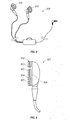
- FIG. 2 is another examplary handheld communication device having a shape-adaptable surface for the audio port in accordance with an examplary embodiment
- FIG. 3 is a side view of the exemplary handheld communication device illustrated in FIG. 1 showing the cross-section view of the audio port having a shape-adaptable surface in accordance with an exemplary embodiment
- FIG. 4 is a side view of the exemplary handheld communication device illustrated in FIG. 1 showing the cross-section view of the audio port having a shape-adaptable surface having an outer surface in accordance with an alternative exemplary embodiment;
- FIG. 5 is a side view of the exemplary handheld communication device illustrated in FIG. 1 showing the cross-section view of the audio port having a shape-adaptable surface in accordance with an alternative exemplary embodiment
- FIG. 6A is a partial side cross-section view of the exemplary handheld communication device illustrated in FIG. 1 in accordance with an exemplary embodiment where the shape-adaptable surface has not been activated;
- FIG. 6B is a partial side cross-section view of the exemplary handheld communication device illustrated in FIG. 1 in accordance with an exemplary embodiment where the shape-adaptable surface has been activated;
- FIG. 6C is a partial top cross-section view of the exemplary handheld communication device illustrated in FIG. 1 in accordance with an exemplary embodiment where the shape-adaptable surface has been activated;
- FIG. 6D is a front plan view of an object that can be spaced from a device having a shape-adaptable surface for an audio port;
- FIG. 6E is a partial top cross-section view of the exemplary handheld communication device illustrated in FIG. 1 in accordance with another exemplary embodiment where the shape-adaptable surface has been activated;
- FIG. 7 is a cross-section view of the shape-adaptable surface in accordance with an exemplary embodiment
- FIG. 8 is another exemplary device having a shape adaptable surface for an audio port
- FIG. 9 is a side cross-section view of the exemplary device illustrated in FIG. 8 ;
- FIG. 10 is a block diagram illustrating the communication between an electronic device and a processor coupled with a shape-adaptable surface for an audio port in accordance with an exemplary embodiment.
- shape-adaptable surface for an audio port. While the following description describes the shape-adaptable surface in relation to an audio port for a handheld mobile communication device, one of ordinary skill in the art will appreciate that the shape-adaptable surface can be implemented with audio ports for portable speakers, headphones, radio-transmitting head phones, gaming chairs having speakers positioned at the head of the chair, audio earphones, portable handheld gaming devices, portable handheld audio devices, or the like.
- exemplary handheld communication devices 100 having a shape-adaptable surface 112 for an audio port 110 in accordance with an exemplary embodiment are illustrated.
- the communication device 100 is illustrated including a body housing a display screen 122, a processor module (not pictured), the audio port 110, and a keyboard 132 comprising a keyfield having alphanumeric keys 140 arranged in a keyboard layout 146, numeric keys 142, and other function keys 144.
- the communication device 100 is a handheld wireless communication device
- the communication device 100 can comprise a personal digital assistant (PDA), handheld electronic devices, wireless communication devices, cellular phones, cellular smart-phones, and wireless organizers. While FIGS.
- PDA personal digital assistant
- the keyboard 132 can be displayed on a dynamic touch display comprising the display screen 122 and a touch location sensor (not shown).
- the surface of the front face of the handheld communication device 100 includes the shape-adaptable surface 112 that surrounds and is operatively coupled with the audio port 110.
- the audio port 110 can be a speaker port or any other element that can transmit or reproduce sound.
- FIG. 3 is a side view of the handheld communication device 100 depicted in FIG. 1 showing a cross-section view of the audio port 110.
- the audio port 110 is coupled to a sensor 114 which is in turn coupled to the shape-adaptable surface 112. As seen in FIG. 3 , the shape-adaptable surface 112 is integrated with a housing 102 of the device 100. While the source of sound generation is not shown, the audio port 110 can be coupled to a speaker, an audio sound system, or other sound generation device.
- the shape-adaptable surface 112 can also be coupled an outer surface 116.
- the outer surface 116 can be a flexible material that can conform to the shape-adaptable surface 112.
- the outer surface 116 can be a flexible material that matches the color and texture of the housing 102 of the device 100, thereby concealing the shape-adaptable surface 112.
- the outer surface 116 can be a cover, a binding layer, or other surface that allows the shape-adaptable surface to be held together with the sensors 114 and the audio port 110.
- the audio port 110 can be coupled to a speaker, an audio sound system, or other sound generation device. In at least another embodiment, the audio port 110 and the sound generation device can be assembled as one unit.
- the shape-adaptable surface 112 can be disposed on the surface of the housing 102 of the device 100. While the source of sound generation is not shown, the audio port 110 can be coupled to a speaker, an audio sound system, or other sound generation device. In at least another embodiment, the audio port 110 and the sound generation device can be assembled as one unit.
- FIGS. 6A-6C are partial cross-section views of the speaker portion of the handheld communication device 100 of FIG. 1 .
- the device 100 comprises a layer of shape-adaptable surface 112 having a plurality of portions 120, a layer of a plurality of sensors 114 coupled to the shape-adaptable surface 112, the audio port 110 of the device 100, and a processor (not shown) operatively coupled to the shape-adaptable surface 112 and to the sensors 114.
- the plurality of sensors 114 are operative to sense a plurality of distances 620, 630 between an object 600, for example an ear, in spaced relation to the device 100 and the shape-adaptable surface 112.
- the sensors 114 can be integrated with the shape-adaptable surface 112 or can be disposed on top or beneath the shape-adaptable surface 112.
- the processor is configured to control some of the plurality of portions 120 of the shape-adaptable surface 112 to adjust the plurality of distances 620, 630 between the object 600 in spaced relation to the device 100 and the portions of the shape-adaptable surface 112.
- the processor can also be configured to control the shape-adaptable surface 112 to provide a channel 118 between a sound receiver 640 of the object 600 and the audio port 110 of the device 100.
- the audio coupling between the object 600 and the audio port 110 is enhanced.
- the channel 118 can result in improved sound quality and sound delivery from the audio port 110 to the sound receiver 640 of the object 600.
- the transfer of sound waves is enhanced by allowing the sound waves to travel more effectively and without significant distortion to the sound receiver 640.
- FIG 6A is a partial cross-section view of a portion of the handheld communication device 100 having an object 600 in spaced relation to the shape-adaptable surface 112, where the shape-adaptable surface has not been activated.
- the object 600 illustrated in FIG 6A is an ear.
- the illustrated portion of the handheld communication device 100 is the speaker portion of the device 100.
- the cross-section of the speaker portion of the device 100 can include the audio port 110 coupled to a sound generation device (not shown).
- the audio port 110 delivers sound from the sound generation device to the sound receiver 640 of an object in spaced relation to the device 100.
- the audio port 110 delivers sound from the sound generation device to the ear canal.
- the layer of sensors 114 can be displaced around the audio port 110.
- the audio port 110 can be integrated with the sensors 114.
- the layer of shape-adaptable surface 112 is disposed on top of the layer of sensors 114.
- the shape-adaptable surface 112 and the sensors 114 can be integrated into one layer or the layer of sensors 114 can be disposed on top of the shape-adaptable surface 112.
- the sensors 114 can be constructed from a suitable flexible material to accommodate the flexibility of the shape-adaptable surface 112.
- the shape-adaptable surface 112 can have the plurality of portions 120. In alternative embodiments, the shape-adaptable surface 112 can be a single layer without the plurality of portions.
- FIG. 6A illustrates the shape-adaptable surface 112, the sensors 114, and the audio port 110 disposed on a support surface 124.
- the support surface 124 can be a PCB board, a metal support surface, a rubber support surface, or other type of support surface.
- FIG. 6A also illustrates the spatial relation between the ear 600 and the handheld communication device 100. As illustrated, the ear 600 has at least one of protrusions, valleys, ridges, convex portions, and concave portions.
- Reference numerals 620 and 630 refer to the plurality of distances between points on the ear and the shape-adaptable surface 112.
- the plurality of distances 620, 630 will vary depending on the points on the protrusions, valleys, ridges, convex portions, and concave portions of the ear 600 that are sensed by the sensors 114.
- the distance between the ear canal (the sound receiver 640 of the ear) and the shape-adaptable surface 112 is noted as reference numeral 630. In FIG.
- the shape-adaptable surface 112 has not been activated, so the shape-adaptable surface 112 has not yet been controlled to reduce the distances 620, 630 between the points of the ear 600 and the shape-adaptable surface 112 or controlled to form a channel between the audio port 110 and the sound receiver 640 of the ear.
- FIG. 6B is a partial cross-section view of a portion of the handheld communication device 100 illustrated in FIG. 6A having an object 600 in spaced relation to the shape-adaptable surface 112, where the shape-adaptable surface has been activated.
- portions 120 of the shape-adaptable surface 112 have been controlled to adjust the plurality of distances 620, 630 between the ear 600 and the shape-adaptable surface 112.
- the plurality of portions 120 has also been controlled to form a channel 118 between the sound receiver 640 and the audio port 110.
- FIG. 6C is a partial top cross-section view of a portion of the handheld communication device 100 illustrated in FIG. 6B having the object 600 in spaced relation to the shape-adaptable surface 112, where the shape adaptable surface 112 has been activated.
- portions 120 of the shape-adaptable surface 112 have been controlled to adjust the plurality of distances 620, 630 between the ear 600 and the shape-adaptable surface 112.
- the plurality of portions 120 has also been controlled to form a channel 118 between the sound receiver 640 and the audio port 110.
- the channel 118 can be formed in a straight line, a curve, a series of line segments, or as needed to allow sound to travel between the audio port 110 and the sound receiver 640.
- FIG. 6D is a front plan view of the object 600 that is an ear.
- the object 600 can have a perimeter 660 which can be sensed by sensors 114 of the shape-adaptable surface 112 for the audio port 110 when the object 600 is in spaced relation to the device 100 having the shape-adaptable surface 112.
- FIG. 6E is a partial top cross-section view of a portion of the handheld communication device 100 illustrated in FIG. 6A having the object 600 in spaced relation to the shape-adaptable surface 112, where the shape-adaptable surface 112 has been activated.
- the shape-adaptable surface 112 has been activated and controlled to adjust the plurality of distances 620, 630 between the perimeter 660 of the object 600 and the shape-adaptable surface 112.
- FIG. 7 is a cross-sectional view of an alternative embodiment of the shape-adaptable surface 112 for an audio port 110.
- FIG. 7 illustrates a portion of the handheld communication 100 device having the shape-adaptable surface 112 that comprises an electroactive polymer layer 712 or film.
- the shape adaptable surface 112 can comprise a shape memory alloy, a flexible skin or gel having a mechanical actuation structure, a flexible skin having a hydraulic actuation structure, a flexible skin having an expandable gas actuation structure, or the like.
- the shape-adaptable surface 112 can include a control portion 710.
- the control portion 710 is a layer having an array of electrodes.
- the electrodes can be operatively coupled to the sensors 114 and the shape-adaptable surface 112.
- the processor in response to the sensed distances between an object and the shape-adaptable surface 112, the processor can control the shape-adaptable surface 112 and send signals to the control portion 710 to actuate particular electrodes, thereby activating and shaping portions of the electroactive polymer film 712 and creating an acoustical connection or coupling between the object 600 and the audio port 110.
- the shape-adaptable surface 112 can also include an outer surface 116 that provides for small changes in shape.
- the outer surface 116 can be a relatively thin foam or gel layer.
- the processor can activate portions of the electroactive polymer layer 712 to change shape.
- the activated portions of the electroactive polymer film 712 will rise up, push against, and push through the portions of the outer surface 116 to create ridges or convex shapes in the outer surface 116.
- the ridges and convex shapes then contact the object 600, such as an ear, to create a suitable acoustical connection between the object 600 and the audio port 110.
- control portion 710 can be interlaced within the shape-adaptable surface 112 or integrated with the shape-adaptable surface 112.
- the control portion 710 can be an array of electrodes interlaced within flexible material, such as polyurethane, rubber, gel, or silicone. With such flexible material, the intersection of the columns and the rows of electrodes can form pockets which provide a frame for the shape-adjustable layer 112 to create shapes when activated.
- the processor controls the shape-adaptable layer 112
- the processor can transmit signals to the control portion 710, thereby activating some of the electrodes to create shapes within the flexible material.
- the control portion 710 can be constructed using MEMS (microelectrical mechanical structures), expandable gas actuation structures, hydraulic actuation structures, or a shape memory alloy structure.
- FIG. 8 is an alternative embodiment of a shape-adaptable surface for an audio port.
- FIG. 8 illustrates a pair of ear phones 800 having a shape-adaptable surface 812 on each of the ear phone pieces.
- FIG. 9 is a cross-sectional view of one of the ear phone 800 pieces.
- the earphone 800 piece includes an audio port 810, the shape-adaptable surface 812 that has a plurality of portions 820 and that is coupled to a plurality of sensors 814, and a processor (not shown) coupled to the shape-adaptable surface 812 and to the plurality of sensors 814.
- the sensors 814 can be disposed on a support surface 824 such as a PCB board, rubber surface, metal plate, or the like.
- the sensors 814 are coupled to the shape-adaptable surface 812 and operative to sense a plurality of distances between an object in spaced relation to the ear phone 800 piece and the shape-adaptable surface 812.
- the processor is operatively coupled to the shape-adaptable surface 812 and to the plurality of sensors 814 and configured to control a plurality of portions 820 of the shape-adaptable surface 812 to adjust the plurality of distances between the object and the shape-adaptable surface 812 and to provide a channel between the sound receiver of the object and the audio port 810 of the ear phone 800 pieces.
- the same method of increasing the audio coupling between an object and an audio port as described herein in relation to a handheld communication device can be implemented with the ear phones illustrated in FIG. 8 .
- a method for increasing the audio coupling between the object 600 and the audio port 110 on the device 100 comprising the shape-adaptable surface 112 can include sensing the plurality of distances 620, 630 between the object 600 and the shape shape-adaptable surface 112 and controlling the plurality of portions 120 of the shape-adaptable surface 112 to adjust the plurality of distances 620, 630 and to form the channel 118 between the audio port 110 and the sound receiver 640 of the object 110, wherein the channel 118 directly couples the sound receiver 640 of the object 600 and the audio port 110. (See FIG. 6A ).
- the sensors 114 sense the presence of the object 600 and sense the plurality of distances 620, 630 between various points on the object 600 and portions of the shape-adaptable surface 112 of the device 110.
- the object 600 can be an audio input device, a microphone, or the like.
- the object 600 is an ear of a user of the handheld communication device 100.
- the sensors 114 sense the ear and begin sensing the distances 620, 630 between points on the ear and the plurality of portions 120 of the shape-adaptable surface 112.
- the processor controls the shape-adaptable surface 112 in response to the distances 620, 630 sensed by the plurality of sensors 114.
- the processor adjusts portions of the shape-adaptable surface 112 to create an auditory coupling between the ear and the shape-adaptable surface 112 to provide improved sound delivery from the audio port 110 to the ear.
- the shape-adaptable surface 112 can be controlled and adjusted to conform to the shape of the object.
- the ear has at least one of protrusions, ridges, valleys, concave portions, and convex portions.
- the processor can adjust the shape-adaptable surface 112 to contact points on the ear, thereby reducing certain gaps created between the protrusions, ridges, valleys, concave portions, and convex portions of the ear and the device 100.
- the processor can control the shape-adaptable surface 112 to extend some of the plurality of portions 120 of the shape-adaptable surface 112 away from the device 100 in the direction of the ear, thereby reducing the gaps created by concave portions and valleys of the ear.
- the processor can also control the shape-adaptable surface 112 to retract some of the plurality of portions 120 of the shape-adaptable surface 112 away from the object 600 in the direction of the device 100 thereby relaxing any excess pressure placed on the shape-adaptable surface 112 by the convex portions and ridges of the ear.
- the shape-adaptable surface 112 is controlled to form an auditory coupling between the ear and the device 100 thereby improving sound quality and reducing the chance of muffled or dampened sounds that can result from the excess pressure placed between convex portions and ridges of the ear.
- the ability to retract portions of the shape-adaptable surface 112 reduces the chance that a complete seal can be formed between the ridges and convex portions of the object 600 and the shape-adaptable surface 112 of the device 100 which can prevent or block sound travel to the sound receiver 640 of the object 600.
- the processor can control the shape-adaptable surface 112 to form the channel 118 between the sound receiver 640 of an object and the audio port 110 which can provide a direct path for sound to travel from the audio port 110 to the sound receiver 640.
- An exemplary embodiment of such a method can include making a determination that an area of the object 600 is the sound receiver 640.
- the method can include controlling the shape-adaptable surface 112 accordingly to form the acoustical channel 118 between the sound receiver 640 of the object 600 and the audio port 110.
- the processor can make a determination based on the sensed plurality of distances 620, 630 between the ear and the shape-adaptable surface 112 that the sound receiver 640 of the ear is the ear canal.
- the determination of the ear canal can be made by comparing the sensed distances 620, 630 to predetermined thresholds.
- the processor can include a first predetermined threshold and a second predetermined threshold, where the second predetermined threshold is greater than the first. If a sensed distance 630 is determined to be greater than the second predetermined threshold, the processor can identify that the area of the ear at the sensed distance 630 that is greater than the second predetermined threshold is the ear canal.
- the processor can then determine and identify that the sensed distance 630 between the shape-adaptable surface 112 and the ear canal is a gap distance 630.
- the processor can then control and adjust the shape-adaptable surface 112 to increase the gap distance 630 between the ear canal and the shape-adaptable surface 112 to provide the channel 118 between the ear canal and audio port 110 for direct delivery of sound.
- the sensors 114 can be used in conjunction with the processor to determine the plurality of distances 620, 630 between points of the object 600 and the plurality of portions 120 of the shape-adaptable surface 112.
- the sensors 114 can be capacitance sensors. Some objects can carry an electrical charge which can be sensed by capacitance sensors. With capacitance sensors, the sensors 114 can determine the strength of the electrical charge which is correlated to the distance between the object 600 and the shape-adaptable surface 112.
- the processor can control the shape-adaptable surface 112 to reduce the distances 620 between the object 600 and the shape-adaptable surface 112 and can control the shape-adaptable surface 112 to form the direct channel 118 between the sound receiver 640 of the object 600 and the audio port 110 of the device 100.
- the sensors 114 can be pressure sensors, strain gauges, resistive sensors piezoelectric sensors, displacement sensors or the like.
- the device 100 can have sensors 114 that are pressure sensors that can be coupled to various portions 120 of the shape-adaptable surface 112.
- the plurality of pressure sensors 114 can detect the amount of pressure placed on the shape-adaptable surface 112 by the object 600. Since the processor is coupled to the sensors 114, the processor can determine the plurality of distances 620, 630 between points on the object 600 and the plurality of portions 120 of the shape-adaptable surface 112 because pressure can be a function of the distance between the object 600 and the shape-adaptable surface 112. For example as illustrated in FIGS.
- the pressure sensors 114 can sense the convex portions and ridges of the ear because those portions will contact and exert pressure on the shape-adaptable surface 112. For the concave portions and valleys of the ear, the pressure sensors 114 can sense a zero pressure at those portions of the shape-adaptable surface 112.
- the processor can control the shape-adaptable surface 112 to extend the portions of the shape-adaptable surface 112 until a non-zero pressure is sensed, which indicates the shape-adaptable surface 112 has contacted the ear.
- the processor can continue to extend portions of the shape-adaptable surface 112 until a first predetermined threshold is met.
- the processor can extend the portion of the shape-adaptable surface 112 until a second predetermined threshold is exceeded.
- the second predetermined threshold is greater than the first predetermined threshold.
- the processor can determine and identify that that portion of the shape-adaptable surface 112 is attempting to contact the sound receiver 640 of the object 600.
- the processor can control the shape-adaptable surface 112 to adjust the gap distance 630 between the shape-adaptable surface 112 and the sound receiver 640 to form the channel 118 between the audio port 110 and the sound receiver 640.
- the processor can control the shape-adaptable surface 112 to increase the gap distance 630 between the audio port 110 and the sound receiver 640.
- the processor can adjust the plurality of portions 120 of the shape-adaptable surface 112 to form the channel 118 between the audio port 110 and the sound receiver 640 of the object 600 based on the plurality of distances 620, 630 sensed by the sensors 114.
- the processor can transmit signals to a control portion 710 of the shape-adaptable surface 112 which in turn can excite certain portions 120 of the shape-adaptable surface 112 to retract towards the device 100 or can excite certain portions 120 to extend away from the device 100 depending on the distances 620, 630 sensed.
- the device 100 having the shape-adaptable surface 112 for the audio port 110 can utilize the sensors 114 and configure the processor to sense and detect the perimeter 660 of the object 600.
- FIG. 6D illustrates an exemplary embodiment of the object 600 that is an ear having the perimeter 660.
- the processor can be further configured to control the plurality of portions 120 of the shape-adaptable surface 112 that are proximate to the perimeter 660 of the object 600.
- the plurality of sensors 114 can sense a plurality of distances 620 between the points on the perimeter 660 of the object 600 and the plurality of portions 120 of the shape-adaptable surface 112. Since the sensors 114 are coupled to the processor, the processor can be configured to determine or detect the perimeter 660 of the object 600 based on the plurality of distances 620 sensed by the sensors 114. As illustrated in FIG. 6E , in response to the detection of the perimeter 660, the processor can adjust the plurality of distances 620 by either extending or retracting the portions 120 of the shape-adaptable surface 112 that are proximate to the perimeter 660 of the object 600 to create an audio coupling or a seal between the perimeter 660 of the object 600 and the shape-adaptable surface 112.
- the audio coupling around the perimeter 660 of the object 600 can also be made in addition to the direct audio channel 118 between the audio receiver 640 and the audio port 110 thereby further ensuring direct delivery of sound to the object 600, wherein the sound is of essentially undiminished quality.
- the method for providing an improved audio coupling between the object 600 and the audio port 110 on the device 100 comprising the shape-adaptable surface 112 can include sensing the plurality of distances 620, 630 between the object 600 and the shape-adaptable surface 112 and controlling the plurality of portions 120 of the shape-adaptable surface 112 to adjust the plurality of distances 620, 630 and to form the channel 118 between the audio port 110 and the sound receiver 640 of the object 110, wherein the channel 118 directly couples the sound receiver 640 of the object 600 and the audio port 110.
- the plurality of sensors 114 coupled to the shape-adaptable surface 112 and the processor can be used to sense the plurality of distances 620, 630 between the object 600 and the shape-adaptable surface 112.
- the processor can send signals to a control portion 710 that controls the plurality of portions 120 of the shape-adaptable surface 112.
- the processor can control the shape-adaptable surface 112 to retract some of the plurality of portions away from the object 600 in the direction of the device or extend some of the plurality of portions away from the device 100 in the direction of the object 600.
- the processor shapes the shape-adaptable surface 112 to reduce the gaps between the shape-adaptable surface 112 and the object 600. As a result, an audio coupling can be formed to allow sound from the audio port 110 to the sound receiver 640 of the object 600.
- some of the plurality of portions of shape-adaptable surface 112 can be extended or retracted to form the channel 118 between the audio port 110 and the sound receiver 640 which can provide a less obstructed path for sound to travel from the audio port 110 to the sound receiver 640.
- FIG. 10 is a block diagram of the handheld communication device 100 depicted in at least FIG. 1 that includes a processor module 138 that controls the operation of the communication device 100.
- a communication subsystem 311 performs all communication transmission and reception with the wireless network 319.
- the processor module 138 further can be connected with an auxiliary input/output (I/O) subsystem 328 which can be connected to the communication device 100.
- the processor module 138 can be connected to a serial port (for example, a Universal Serial Bus port) 330 which can allow for communication with other devices or systems.
- the display 122 can be connected to the processor module 138 to allow for displaying of information to an operator of the communication device 100.
- the keyboard 132 can also be connected with the processor module 138.
- a keyboard controller is in communication with the processor in order to send or relay messages corresponding to key pressings of the keyboard 132 to the processor 138.
- the communication device 100 can include the audio port 110, a microphone 336, random access memory (RAM) 326, and flash memory 324, all of which can be connected to the processor module 138.
- Other similar components can be provided on the device 100 as well and optionally connected to the processor module 138.
- Other communication subsystems 340 and other communication device subsystems 342 are generally indicated as being functionally connected with the processor module 138 as well.
- An example of a communication subsystem 340 is that of a short range communication system such as BLUETOOTH® communication module or a WI-FI® communication module (a communication module in compliance with IEEE 802.11 set of protocols) and associated circuits and components.
- the processor module 138 is able to perform operating system functions and enables execution of programs on the communication device 100.
- not all of the above components can be included in the communication device 100.
- the keyboard 132 is not provided as a separate component, and is displayed as required on a dynamic touch display.
- the keyboard 132 can be displayed as a touchscreen keyboard.
- a touchscreen module can be incorporated in such an embodiment such that it is in communication with the processor 138. When inputs are received on the touchscreen keyboard, the touchscreen module can send or relay messages corresponding to those inputs to the processor.
- the auxiliary I/O subsystem 328 can take the form of a trackball navigation tool as illustrated in the examplary embodiment shown in FIG. 1 , or a thumbwheel, a navigation pad, a joystick, touch-sensitive interface, or other I/O interface. While the above examples have been provided in relation to the auxiliary I/O subsystem 328, other subsystems capable of providing input or receiving output from the communication device 100 are considered within the scope of this disclosure. Other keys can be placed along the side of the communication device 100 to function as escape keys, volume control keys, scrolling keys, power switches, or user programmable keys, and can likewise be programmed accordingly.
- the communication device 100 is equipped with components to enable operation of various programs, as shown in FIG. 10 .
- the flash memory 324 is enabled to provide a storage location for the operating system 357, device programs 358, and data.
- the operating system 357 is generally configured to manage other programs 358 that are also stored in memory 324 and executable on the processor.
- the operating system 357 honors requests for services made by programs 358 through predefined program 358 interfaces. More specifically, the operating system 357 typically determines the order in which multiple programs 358 are executed on the processor and the execution time allotted for each program 358, manages the sharing of memory 324 among multiple programs 358, handles input and output to and from other device subsystems 342, and so on.
- operating system 357 can typically interact directly with the operating system 357 through a user interface which can include the keyboard 132 and display screen 122. While in an examplary embodiment the operating system 357 is stored in flash memory 324, the operating system 357 in other embodiments is stored in read-only memory (ROM) or similar storage element (not shown). As those skilled in the art will appreciate, the operating system 357, device program 358 or parts thereof can be loaded in RAM 326 or other volatile memory.
- ROM read-only memory
- the flash memory 324 contains programs 358 for execution on the communication device 100 including an address book 352, a personal information manager (PIM) 354, and the device state 350. Furthermore, programs 358 and other information 356 including data can be segregated upon storage in the flash memory 324 of the communication device 100.
- PIM personal information manager
- the communication device 100 When the communication device 100 is enabled for two-way communication within the wireless communication network 319, it can send and receive messages from a mobile communication service.
- Examples of communication systems enabled for two-way communication include, but are not limited to, the General Packet Radio Service (GPRS) network, the Universal Mobile Telecommunication Service (UMTS) network, the Enhanced Data for Global Evolution (EDGE) network, the Code Division Multiple Access (CDMA) network, High-Speed Packet Access (HSPA) networks, Universal Mobile Telecommunication Service Time Division Duplexing (UMTS-TDD), Ultra Mobile Broadband (UMB) networks, Worldwide Interoperability for Microwave Access (WiMAX), and other networks that can be used for data and voice, or just data or voice.
- GPRS General Packet Radio Service
- UMTS Universal Mobile Telecommunication Service
- EDGE Enhanced Data for Global Evolution
- CDMA Code Division Multiple Access
- UMTS-TDD Universal Mobile Telecommunication Service Time Division Duplexing
- UMB Ultra Mobile Broadband
- the communication device 100 can require a unique identifier to enable the communication device 100 to transmit and receive messages from the communication network 319. Other systems may not require such identifying information.
- GPRS, UMTS, and EDGE use a Subscriber Identity Module (SIM) in order to allow communication with the communication network 319.
- SIM Subscriber Identity Module
- RUIM Removable User Identity Module
- the RUIM and SIM card can be used in multiple different communication devices 100.
- the communication device 100 can be able to operate some features without a SIM/RUIM card, but it will not be able to communicate with the network 319.
- a SIM/RUIM interface 344 located within the communication device 100 allows for removal or insertion of a SIM/RUIM card (not shown).
- the SIM/RUIM card features memory and holds key configurations 351, and other information 353 such as identification and subscriber related information. With a properly enabled communication device 100, two-way communication between the communication device 100 and communication network 319 is possible.
- the two-way communication enabled communication device 100 is able to both transmit and receive information from the communication network 319.
- the transfer of communication can be from the communication device 100 or to the communication device 100.
- the communication device 100 in the presently described examplary embodiment is equipped with an integral or internal antenna 318 for transmitting messages to the communication network 319.
- the communication device 100 in the presently described examplary embodiment is equipped with another antenna 316 for receiving communication from the communication network 319.
- These antennae (316, 318) in another examplary embodiment are combined into a single antenna (not shown).
- the antenna or antennae (316, 318) in another embodiment are externally mounted on the communication device 100.
- the communication device 100 When equipped for two-way communication, the communication device 100 features a communication subsystem 311. As is understood in the art, this communication subsystem 311 is modified so that it can support the operational needs of the communication device 100.
- the subsystem 311 includes a transmitter 314 and receiver 312 including the associated antenna or antennae (316, 318) as described above, local oscillators (LOs) 313, and a processing module 320 which in the presently described examplary embodiment is a digital signal processor (DSP) 320.
- DSP digital signal processor
- communication by the communication device 100 with the wireless network 319 can be any type of communication that both the wireless network 319 and communication device 100 are enabled to transmit, receive and process. In general, these can be classified as voice and data.
- Voice communication generally refers to communication in which messages for audible sounds are transmitted by the communication device 100 through the communication network 319.
- Data generally refers to all other types of communication that the communication device 100 is capable of performing within the constraints of the wireless network 319.
- Example device programs that can depend on such data include email, contacts and calendars. For each such program, synchronization with home-based versions of the programs can be desirable for either or both of their long term and short term utility.
- emails are often time sensitive, so substantially real time synchronization can be desired.
- Contacts on the other hand, can be usually updated less frequently without inconvenience. Therefore, the utility of the communication device 100 is enhanced when connectable within a communication system, and when connectable on a wireless basis in the network 319 in which voice, text messaging, and other data transfer are accommodated.
- the shape-adaptable surface 112 can be implemented into the ear pieces of noise-canceling headphones to improve the audio coupling between the user's ear and the audio port of the noise canceling headphones to ensure extraneous noise is blocked out and to ensure a direct path between the user's ear canal and the audio port.
- the shape-adaptable surface can also be implemented into the speaker portions of walkie-talkies. Shape-adaptable surface can also be implemented around plug connections for speakers or audio outputs to ensure a direct audio coupling for sound to travel from the audio port to and through the plug.
Landscapes
- Physics & Mathematics (AREA)
- Engineering & Computer Science (AREA)
- Signal Processing (AREA)
- Acoustics & Sound (AREA)
- General Physics & Mathematics (AREA)
- Circuit For Audible Band Transducer (AREA)
- Telephone Set Structure (AREA)
- Details Of Audible-Bandwidth Transducers (AREA)
Abstract
Description
- The present disclosure relates generally to audio ports of electronic devices. More specifically, the present disclosure relates to shape-adaptable surfaces for audio ports of electronic devices.
- With the advent of more robust audio electronic systems, advancements of electronic devices are becoming more prevalent. Electronic devices can provide a variety of functions including, for example, telephonic, audio/video, and gaming functions. Handheld electronic devices can include mobile stations such as cellular telephones, smart telephones, portable gaming systems, audio headphones, wireless headsets for cellular phones, handheld video players, handheld audio players, audio headphones, and portable MP3 players.
- Some electronic devices can include a speaker portion having an audio port that provides sound to a user of the device. For example, the device may have an audio port on a substantially flat surface of the device. The substantially flat surface of the device is then held against the user's head to align the audio port with the user's ear. However, because the user's ear is not flat in shape, gaps form between the surface of the device and the user's ear. As a result, some of the sound delivered by the audio port dissipates through the gaps, thereby reducing sound quality.
- In other electronic devices, the speaker portion having an audio port can be made of a deformable material, such as a foam, an elastomeric, a soft rubber material, or a gel. When an object contacts and exerts pressure on the speaker portion, the speaker portion deforms to cushion the object and to equalize pressure between the speaker portion and the object. With such devices, the speaker portion might not deform enough to create a sufficient audio coupling, thereby resulting in gaps between the object and the deformable material. Again, such gaps can reduce sound quality. Contrastingly, some devices have deformable surfaces that are so deformable that the reformable material makes a complete seal with the ear such that no gaps exist between the user's ear and the surface of the device. For example, such a situation can occur if the device is misaligned with the ear. If the seal is so complete, sound cannot travel well from the audio port of the device to the user's ear because the lack of any gaps blocks or muffles the sound.
- Embodiments of the present application will now be described, by way of example only, with reference to the attached Figures, wherein:
-
FIG. 1 is an examplary handheld communication device having a shape-adaptable surface for the audio port in accordance with an examplary embodiment; -
FIG. 2 is another examplary handheld communication device having a shape-adaptable surface for the audio port in accordance with an examplary embodiment; -
FIG. 3 is a side view of the exemplary handheld communication device illustrated inFIG. 1 showing the cross-section view of the audio port having a shape-adaptable surface in accordance with an exemplary embodiment; -
FIG. 4 is a side view of the exemplary handheld communication device illustrated inFIG. 1 showing the cross-section view of the audio port having a shape-adaptable surface having an outer surface in accordance with an alternative exemplary embodiment; -
FIG. 5 is a side view of the exemplary handheld communication device illustrated inFIG. 1 showing the cross-section view of the audio port having a shape-adaptable surface in accordance with an alternative exemplary embodiment; -
FIG. 6A is a partial side cross-section view of the exemplary handheld communication device illustrated inFIG. 1 in accordance with an exemplary embodiment where the shape-adaptable surface has not been activated; -
FIG. 6B is a partial side cross-section view of the exemplary handheld communication device illustrated inFIG. 1 in accordance with an exemplary embodiment where the shape-adaptable surface has been activated; -
FIG. 6C is a partial top cross-section view of the exemplary handheld communication device illustrated inFIG. 1 in accordance with an exemplary embodiment where the shape-adaptable surface has been activated; -
FIG. 6D is a front plan view of an object that can be spaced from a device having a shape-adaptable surface for an audio port; -
FIG. 6E is a partial top cross-section view of the exemplary handheld communication device illustrated inFIG. 1 in accordance with another exemplary embodiment where the shape-adaptable surface has been activated; -
FIG. 7 is a cross-section view of the shape-adaptable surface in accordance with an exemplary embodiment; -
FIG. 8 is another exemplary device having a shape adaptable surface for an audio port; -
FIG. 9 is a side cross-section view of the exemplary device illustrated inFIG. 8 ; and -
FIG. 10 is a block diagram illustrating the communication between an electronic device and a processor coupled with a shape-adaptable surface for an audio port in accordance with an exemplary embodiment. - It will be appreciated that for simplicity and clarity of illustration, where appropriate, reference numerals have been repeated among the different figures to indicate corresponding or analogous elements. In addition, numerous specific details are set forth in order to provide a thorough understanding of the embodiments described herein. However, it will be understood by those of ordinary skill in the art that the embodiments described herein can be practiced without these specific details. In other instances, methods, procedures and components have not been described in detail so as not to obscure the related relevant feature being described. Also, the description is not to be considered as limiting the scope of the embodiments described herein.
- The following figures describe a shape-adaptable surface for an audio port. While the following description describes the shape-adaptable surface in relation to an audio port for a handheld mobile communication device, one of ordinary skill in the art will appreciate that the shape-adaptable surface can be implemented with audio ports for portable speakers, headphones, radio-transmitting head phones, gaming chairs having speakers positioned at the head of the chair, audio earphones, portable handheld gaming devices, portable handheld audio devices, or the like.
- Referring to
FIGS. 1 and2 , exemplaryhandheld communication devices 100 having a shape-adaptable surface 112 for anaudio port 110 in accordance with an exemplary embodiment are illustrated. InFIGS. 1 and2 , thecommunication device 100 is illustrated including a body housing adisplay screen 122, a processor module (not pictured), theaudio port 110, and akeyboard 132 comprising a keyfield havingalphanumeric keys 140 arranged in akeyboard layout 146,numeric keys 142, andother function keys 144. While the illustrated embodiment shows thecommunication device 100 is a handheld wireless communication device, in other embodiments, thecommunication device 100 can comprise a personal digital assistant (PDA), handheld electronic devices, wireless communication devices, cellular phones, cellular smart-phones, and wireless organizers. WhileFIGS. 1 and2 depict thekeyboard 132 having depressiblealphanumeric keys 140,numeric keys 142, andfunction keys 144, in other embodiments, thekeyboard 132 can be displayed on a dynamic touch display comprising thedisplay screen 122 and a touch location sensor (not shown). Also illustrated inFIGS. 1 and2 , the surface of the front face of thehandheld communication device 100 includes the shape-adaptable surface 112 that surrounds and is operatively coupled with theaudio port 110. Theaudio port 110 can be a speaker port or any other element that can transmit or reproduce sound. -
FIG. 3 is a side view of thehandheld communication device 100 depicted inFIG. 1 showing a cross-section view of theaudio port 110. Theaudio port 110 is coupled to asensor 114 which is in turn coupled to the shape-adaptable surface 112. As seen inFIG. 3 , the shape-adaptable surface 112 is integrated with ahousing 102 of thedevice 100. While the source of sound generation is not shown, theaudio port 110 can be coupled to a speaker, an audio sound system, or other sound generation device. - In an alternative embodiment, as illustrated in
FIG 4 , the shape-adaptable surface 112 can also be coupled anouter surface 116. For example, theouter surface 116 can be a flexible material that can conform to the shape-adaptable surface 112. Additionally, theouter surface 116 can be a flexible material that matches the color and texture of thehousing 102 of thedevice 100, thereby concealing the shape-adaptable surface 112. In alternative embodiments, theouter surface 116 can be a cover, a binding layer, or other surface that allows the shape-adaptable surface to be held together with thesensors 114 and theaudio port 110. While the source of sound generation is not shown, theaudio port 110 can be coupled to a speaker, an audio sound system, or other sound generation device. In at least another embodiment, theaudio port 110 and the sound generation device can be assembled as one unit. - In the alternative embodiment illustrated in
FIG. 5 , the shape-adaptable surface 112 can be disposed on the surface of thehousing 102 of thedevice 100. While the source of sound generation is not shown, theaudio port 110 can be coupled to a speaker, an audio sound system, or other sound generation device. In at least another embodiment, theaudio port 110 and the sound generation device can be assembled as one unit. -
FIGS. 6A-6C are partial cross-section views of the speaker portion of thehandheld communication device 100 ofFIG. 1 . As illustrated inFIGS. 6A -6C , thedevice 100 comprises a layer of shape-adaptable surface 112 having a plurality ofportions 120, a layer of a plurality ofsensors 114 coupled to the shape-adaptable surface 112, theaudio port 110 of thedevice 100, and a processor (not shown) operatively coupled to the shape-adaptable surface 112 and to thesensors 114. The plurality ofsensors 114 are operative to sense a plurality ofdistances object 600, for example an ear, in spaced relation to thedevice 100 and the shape-adaptable surface 112. While a separate layer ofsensors 114 is illustrated, in alternative embodiments, thesensors 114 can be integrated with the shape-adaptable surface 112 or can be disposed on top or beneath the shape-adaptable surface 112. The processor is configured to control some of the plurality ofportions 120 of the shape-adaptable surface 112 to adjust the plurality ofdistances object 600 in spaced relation to thedevice 100 and the portions of the shape-adaptable surface 112. The processor can also be configured to control the shape-adaptable surface 112 to provide achannel 118 between asound receiver 640 of theobject 600 and theaudio port 110 of thedevice 100. By controlling the shape-adaptable surface 112 and adjusting thedistances adaptable surface 112 and theobject 600, the audio coupling between theobject 600 and theaudio port 110 is enhanced. For example, thechannel 118 can result in improved sound quality and sound delivery from theaudio port 110 to thesound receiver 640 of theobject 600. As thechannel 118 couples theaudio port 110 to thesound receiver 640, the transfer of sound waves is enhanced by allowing the sound waves to travel more effectively and without significant distortion to thesound receiver 640. -
FIG 6A is a partial cross-section view of a portion of thehandheld communication device 100 having anobject 600 in spaced relation to the shape-adaptable surface 112, where the shape-adaptable surface has not been activated. Theobject 600 illustrated inFIG 6A is an ear. The illustrated portion of thehandheld communication device 100 is the speaker portion of thedevice 100. The cross-section of the speaker portion of thedevice 100 can include theaudio port 110 coupled to a sound generation device (not shown). Theaudio port 110 delivers sound from the sound generation device to thesound receiver 640 of an object in spaced relation to thedevice 100. InFIG. 6A , theaudio port 110 delivers sound from the sound generation device to the ear canal. In the illustrated embodiment, the layer ofsensors 114 can be displaced around theaudio port 110. In an alternative embodiment, theaudio port 110 can be integrated with thesensors 114. As illustrated, the layer of shape-adaptable surface 112 is disposed on top of the layer ofsensors 114. In an alternative embodiment, the shape-adaptable surface 112 and thesensors 114 can be integrated into one layer or the layer ofsensors 114 can be disposed on top of the shape-adaptable surface 112. In such embodiments, thesensors 114 can be constructed from a suitable flexible material to accommodate the flexibility of the shape-adaptable surface 112. - Still referring to the embodiment illustrated in
FIG. 6A , the shape-adaptable surface 112 can have the plurality ofportions 120. In alternative embodiments, the shape-adaptable surface 112 can be a single layer without the plurality of portions.FIG. 6A illustrates the shape-adaptable surface 112, thesensors 114, and theaudio port 110 disposed on asupport surface 124. Thesupport surface 124 can be a PCB board, a metal support surface, a rubber support surface, or other type of support surface.FIG. 6A also illustrates the spatial relation between theear 600 and thehandheld communication device 100. As illustrated, theear 600 has at least one of protrusions, valleys, ridges, convex portions, and concave portions.Reference numerals adaptable surface 112. The plurality ofdistances ear 600 that are sensed by thesensors 114. The distance between the ear canal (thesound receiver 640 of the ear) and the shape-adaptable surface 112 is noted asreference numeral 630. InFIG. 6A , the shape-adaptable surface 112 has not been activated, so the shape-adaptable surface 112 has not yet been controlled to reduce thedistances ear 600 and the shape-adaptable surface 112 or controlled to form a channel between theaudio port 110 and thesound receiver 640 of the ear. -
FIG. 6B is a partial cross-section view of a portion of thehandheld communication device 100 illustrated inFIG. 6A having anobject 600 in spaced relation to the shape-adaptable surface 112, where the shape-adaptable surface has been activated. As illustrated,portions 120 of the shape-adaptable surface 112 have been controlled to adjust the plurality ofdistances ear 600 and the shape-adaptable surface 112. The plurality ofportions 120 has also been controlled to form achannel 118 between thesound receiver 640 and theaudio port 110. -
FIG. 6C is a partial top cross-section view of a portion of thehandheld communication device 100 illustrated inFIG. 6B having theobject 600 in spaced relation to the shape-adaptable surface 112, where the shapeadaptable surface 112 has been activated. As illustrated,portions 120 of the shape-adaptable surface 112 have been controlled to adjust the plurality ofdistances ear 600 and the shape-adaptable surface 112. The plurality ofportions 120 has also been controlled to form achannel 118 between thesound receiver 640 and theaudio port 110. In a top view, thechannel 118 can be formed in a straight line, a curve, a series of line segments, or as needed to allow sound to travel between theaudio port 110 and thesound receiver 640. -
FIG. 6D is a front plan view of theobject 600 that is an ear. Theobject 600 can have aperimeter 660 which can be sensed bysensors 114 of the shape-adaptable surface 112 for theaudio port 110 when theobject 600 is in spaced relation to thedevice 100 having the shape-adaptable surface 112. -
FIG. 6E is a partial top cross-section view of a portion of thehandheld communication device 100 illustrated inFIG. 6A having theobject 600 in spaced relation to the shape-adaptable surface 112, where the shape-adaptable surface 112 has been activated. In the illustrated embodiment, the shape-adaptable surface 112 has been activated and controlled to adjust the plurality ofdistances perimeter 660 of theobject 600 and the shape-adaptable surface 112. -
FIG. 7 is a cross-sectional view of an alternative embodiment of the shape-adaptable surface 112 for anaudio port 110.FIG. 7 illustrates a portion of thehandheld communication 100 device having the shape-adaptable surface 112 that comprises anelectroactive polymer layer 712 or film. In other alternative embodiments, the shapeadaptable surface 112 can comprise a shape memory alloy, a flexible skin or gel having a mechanical actuation structure, a flexible skin having a hydraulic actuation structure, a flexible skin having an expandable gas actuation structure, or the like. In some embodiments, the shape-adaptable surface 112 can include acontrol portion 710. In the exemplary embodiment illustrated inFIG. 7 , thecontrol portion 710 is a layer having an array of electrodes. In at least one embodiment, the electrodes can be operatively coupled to thesensors 114 and the shape-adaptable surface 112. With the particular exemplary embodiment illustrated inFIG. 7 , in response to the sensed distances between an object and the shape-adaptable surface 112, the processor can control the shape-adaptable surface 112 and send signals to thecontrol portion 710 to actuate particular electrodes, thereby activating and shaping portions of theelectroactive polymer film 712 and creating an acoustical connection or coupling between theobject 600 and theaudio port 110. The shape-adaptable surface 112 can also include anouter surface 116 that provides for small changes in shape. For example, theouter surface 116 can be a relatively thin foam or gel layer. With theouter surface 116, the processor can activate portions of theelectroactive polymer layer 712 to change shape. As a result, the activated portions of theelectroactive polymer film 712 will rise up, push against, and push through the portions of theouter surface 116 to create ridges or convex shapes in theouter surface 116. The ridges and convex shapes then contact theobject 600, such as an ear, to create a suitable acoustical connection between theobject 600 and theaudio port 110. - In alternative embodiments, the
control portion 710 can be interlaced within the shape-adaptable surface 112 or integrated with the shape-adaptable surface 112. For example, thecontrol portion 710 can be an array of electrodes interlaced within flexible material, such as polyurethane, rubber, gel, or silicone. With such flexible material, the intersection of the columns and the rows of electrodes can form pockets which provide a frame for the shape-adjustable layer 112 to create shapes when activated. Thus, when the processor controls the shape-adaptable layer 112, the processor can transmit signals to thecontrol portion 710, thereby activating some of the electrodes to create shapes within the flexible material. Alternatively, thecontrol portion 710 can be constructed using MEMS (microelectrical mechanical structures), expandable gas actuation structures, hydraulic actuation structures, or a shape memory alloy structure. -
FIG. 8 is an alternative embodiment of a shape-adaptable surface for an audio port.FIG. 8 illustrates a pair ofear phones 800 having a shape-adaptable surface 812 on each of the ear phone pieces.FIG. 9 is a cross-sectional view of one of theear phone 800 pieces. Theearphone 800 piece includes anaudio port 810, the shape-adaptable surface 812 that has a plurality ofportions 820 and that is coupled to a plurality ofsensors 814, and a processor (not shown) coupled to the shape-adaptable surface 812 and to the plurality ofsensors 814. Thesensors 814 can be disposed on asupport surface 824 such as a PCB board, rubber surface, metal plate, or the like. Thesensors 814 are coupled to the shape-adaptable surface 812 and operative to sense a plurality of distances between an object in spaced relation to theear phone 800 piece and the shape-adaptable surface 812. The processor is operatively coupled to the shape-adaptable surface 812 and to the plurality ofsensors 814 and configured to control a plurality ofportions 820 of the shape-adaptable surface 812 to adjust the plurality of distances between the object and the shape-adaptable surface 812 and to provide a channel between the sound receiver of the object and theaudio port 810 of theear phone 800 pieces. The same method of increasing the audio coupling between an object and an audio port as described herein in relation to a handheld communication device can be implemented with the ear phones illustrated inFIG. 8 . - The method of providing the improved audio coupling will be described in the following paragraphs. For purposes of simplicity and clarity, the method will be described in relation to the
handheld communication device 100 as depicted in at leastFIGS. 1 and6A-6C . - A method for increasing the audio coupling between the
object 600 and theaudio port 110 on thedevice 100 comprising the shape-adaptable surface 112 can include sensing the plurality ofdistances object 600 and the shape shape-adaptable surface 112 and controlling the plurality ofportions 120 of the shape-adaptable surface 112 to adjust the plurality ofdistances channel 118 between theaudio port 110 and thesound receiver 640 of theobject 110, wherein thechannel 118 directly couples thesound receiver 640 of theobject 600 and theaudio port 110. (SeeFIG. 6A ). For example, as theobject 600 approaches thedevice 100, thesensors 114 sense the presence of theobject 600 and sense the plurality ofdistances object 600 and portions of the shape-adaptable surface 112 of thedevice 110. In alternative embodiments, theobject 600 can be an audio input device, a microphone, or the like. - In
FIGS. 6A-6C , theobject 600 is an ear of a user of thehandheld communication device 100. As the ear approaches thehandheld communication device 100, thesensors 114 sense the ear and begin sensing thedistances portions 120 of the shape-adaptable surface 112. The processor controls the shape-adaptable surface 112 in response to thedistances sensors 114. The processor adjusts portions of the shape-adaptable surface 112 to create an auditory coupling between the ear and the shape-adaptable surface 112 to provide improved sound delivery from theaudio port 110 to the ear. - Many objects are not uniform in shape or are not flat. So, the shape-
adaptable surface 112 can be controlled and adjusted to conform to the shape of the object. For example, as illustrated inFIGS. 6A-6C , the ear has at least one of protrusions, ridges, valleys, concave portions, and convex portions. The processor can adjust the shape-adaptable surface 112 to contact points on the ear, thereby reducing certain gaps created between the protrusions, ridges, valleys, concave portions, and convex portions of the ear and thedevice 100. For example, the processor can control the shape-adaptable surface 112 to extend some of the plurality ofportions 120 of the shape-adaptable surface 112 away from thedevice 100 in the direction of the ear, thereby reducing the gaps created by concave portions and valleys of the ear. The processor can also control the shape-adaptable surface 112 to retract some of the plurality ofportions 120 of the shape-adaptable surface 112 away from theobject 600 in the direction of thedevice 100 thereby relaxing any excess pressure placed on the shape-adaptable surface 112 by the convex portions and ridges of the ear. By relaxing the pressure, the shape-adaptable surface 112 is controlled to form an auditory coupling between the ear and thedevice 100 thereby improving sound quality and reducing the chance of muffled or dampened sounds that can result from the excess pressure placed between convex portions and ridges of the ear. Thus, with an active and reactive shape-adaptable surface 112, the ability to retract portions of the shape-adaptable surface 112 reduces the chance that a complete seal can be formed between the ridges and convex portions of theobject 600 and the shape-adaptable surface 112 of thedevice 100 which can prevent or block sound travel to thesound receiver 640 of theobject 600. - Additionally, the processor can control the shape-
adaptable surface 112 to form thechannel 118 between thesound receiver 640 of an object and theaudio port 110 which can provide a direct path for sound to travel from theaudio port 110 to thesound receiver 640. An exemplary embodiment of such a method can include making a determination that an area of theobject 600 is thesound receiver 640. In response to the determination of thesound receiver 640, the method can include controlling the shape-adaptable surface 112 accordingly to form theacoustical channel 118 between thesound receiver 640 of theobject 600 and theaudio port 110. For example, if theobject 600 is an ear, the processor can make a determination based on the sensed plurality ofdistances adaptable surface 112 that thesound receiver 640 of the ear is the ear canal. The determination of the ear canal can be made by comparing the senseddistances distance 630 is determined to be greater than the second predetermined threshold, the processor can identify that the area of the ear at the senseddistance 630 that is greater than the second predetermined threshold is the ear canal. The processor can then determine and identify that the senseddistance 630 between the shape-adaptable surface 112 and the ear canal is agap distance 630. The processor can then control and adjust the shape-adaptable surface 112 to increase thegap distance 630 between the ear canal and the shape-adaptable surface 112 to provide thechannel 118 between the ear canal andaudio port 110 for direct delivery of sound. - The
sensors 114 can be used in conjunction with the processor to determine the plurality ofdistances object 600 and the plurality ofportions 120 of the shape-adaptable surface 112. For example, thesensors 114 can be capacitance sensors. Some objects can carry an electrical charge which can be sensed by capacitance sensors. With capacitance sensors, thesensors 114 can determine the strength of the electrical charge which is correlated to the distance between theobject 600 and the shape-adaptable surface 112. Thus, depending on the senseddistances 620, the processor can control the shape-adaptable surface 112 to reduce thedistances 620 between theobject 600 and the shape-adaptable surface 112 and can control the shape-adaptable surface 112 to form thedirect channel 118 between thesound receiver 640 of theobject 600 and theaudio port 110 of thedevice 100. In alternative embodiments, thesensors 114 can be pressure sensors, strain gauges, resistive sensors piezoelectric sensors, displacement sensors or the like. - In another exemplary embodiment, the
device 100 can havesensors 114 that are pressure sensors that can be coupled tovarious portions 120 of the shape-adaptable surface 112. The plurality ofpressure sensors 114 can detect the amount of pressure placed on the shape-adaptable surface 112 by theobject 600. Since the processor is coupled to thesensors 114, the processor can determine the plurality ofdistances object 600 and the plurality ofportions 120 of the shape-adaptable surface 112 because pressure can be a function of the distance between theobject 600 and the shape-adaptable surface 112. For example as illustrated inFIGS. 6A-6C , if theobject 600 is an ear, thepressure sensors 114 can sense the convex portions and ridges of the ear because those portions will contact and exert pressure on the shape-adaptable surface 112. For the concave portions and valleys of the ear, thepressure sensors 114 can sense a zero pressure at those portions of the shape-adaptable surface 112. In response to zero pressures sensed by thesensors 114, the processor can control the shape-adaptable surface 112 to extend the portions of the shape-adaptable surface 112 until a non-zero pressure is sensed, which indicates the shape-adaptable surface 112 has contacted the ear. The processor can continue to extend portions of the shape-adaptable surface 112 until a first predetermined threshold is met. To determine which area of theobject 600 is thesound receiver 640, the processor can extend the portion of the shape-adaptable surface 112 until a second predetermined threshold is exceeded. In such an embodiment, the second predetermined threshold is greater than the first predetermined threshold. When the processor determines that the second predetermined threshold is exceeded, the processor can determine and identify that that portion of the shape-adaptable surface 112 is attempting to contact thesound receiver 640 of theobject 600. In response to the determination and identification of thesound receiver 640, the processor can control the shape-adaptable surface 112 to adjust thegap distance 630 between the shape-adaptable surface 112 and thesound receiver 640 to form thechannel 118 between theaudio port 110 and thesound receiver 640. For example, the processor can control the shape-adaptable surface 112 to increase thegap distance 630 between theaudio port 110 and thesound receiver 640. - Regardless of the
sensors 114 used, the processor can adjust the plurality ofportions 120 of the shape-adaptable surface 112 to form thechannel 118 between theaudio port 110 and thesound receiver 640 of theobject 600 based on the plurality ofdistances sensors 114. In an alternative embodiment, the processor can transmit signals to acontrol portion 710 of the shape-adaptable surface 112 which in turn can excitecertain portions 120 of the shape-adaptable surface 112 to retract towards thedevice 100 or can excitecertain portions 120 to extend away from thedevice 100 depending on thedistances - Aside from forming the
channel 118 between theaudio port 110 and thesound receiver 640 of theobject 600, thedevice 100 having the shape-adaptable surface 112 for theaudio port 110 can utilize thesensors 114 and configure the processor to sense and detect theperimeter 660 of theobject 600. For example,FIG. 6D illustrates an exemplary embodiment of theobject 600 that is an ear having theperimeter 660. In another alternative embodiment illustrated inFIG. 6E , the processor can be further configured to control the plurality ofportions 120 of the shape-adaptable surface 112 that are proximate to theperimeter 660 of theobject 600. For example, the plurality ofsensors 114 can sense a plurality ofdistances 620 between the points on theperimeter 660 of theobject 600 and the plurality ofportions 120 of the shape-adaptable surface 112. Since thesensors 114 are coupled to the processor, the processor can be configured to determine or detect theperimeter 660 of theobject 600 based on the plurality ofdistances 620 sensed by thesensors 114. As illustrated inFIG. 6E , in response to the detection of theperimeter 660, the processor can adjust the plurality ofdistances 620 by either extending or retracting theportions 120 of the shape-adaptable surface 112 that are proximate to theperimeter 660 of theobject 600 to create an audio coupling or a seal between theperimeter 660 of theobject 600 and the shape-adaptable surface 112. With an audio coupling around theperimeter 660 of theobject 600, sound from theaudio port 110 is less likely to escape from the audio coupling, thereby ensuring delivery of sound to theaudio receiver 640 of theobject 600 without reduced sound quality. The audio coupling around theperimeter 660 of theobject 600 can also be made in addition to thedirect audio channel 118 between theaudio receiver 640 and theaudio port 110 thereby further ensuring direct delivery of sound to theobject 600, wherein the sound is of essentially undiminished quality. - Thus, the method for providing an improved audio coupling between the
object 600 and theaudio port 110 on thedevice 100 comprising the shape-adaptable surface 112 can include sensing the plurality ofdistances object 600 and the shape-adaptable surface 112 and controlling the plurality ofportions 120 of the shape-adaptable surface 112 to adjust the plurality ofdistances channel 118 between theaudio port 110 and thesound receiver 640 of theobject 110, wherein thechannel 118 directly couples thesound receiver 640 of theobject 600 and theaudio port 110. The plurality ofsensors 114 coupled to the shape-adaptable surface 112 and the processor can be used to sense the plurality ofdistances object 600 and the shape-adaptable surface 112. In response to the sensed plurality ofdistances control portion 710 that controls the plurality ofportions 120 of the shape-adaptable surface 112. For example, the processor can control the shape-adaptable surface 112 to retract some of the plurality of portions away from theobject 600 in the direction of the device or extend some of the plurality of portions away from thedevice 100 in the direction of theobject 600. By making these adjustments, the processor shapes the shape-adaptable surface 112 to reduce the gaps between the shape-adaptable surface 112 and theobject 600. As a result, an audio coupling can be formed to allow sound from theaudio port 110 to thesound receiver 640 of theobject 600. Additionally, some of the plurality of portions of shape-adaptable surface 112 can be extended or retracted to form thechannel 118 between theaudio port 110 and thesound receiver 640 which can provide a less obstructed path for sound to travel from theaudio port 110 to thesound receiver 640. -
FIG. 10 is a block diagram of thehandheld communication device 100 depicted in at leastFIG. 1 that includes aprocessor module 138 that controls the operation of thecommunication device 100. Acommunication subsystem 311 performs all communication transmission and reception with thewireless network 319. Theprocessor module 138 further can be connected with an auxiliary input/output (I/O)subsystem 328 which can be connected to thecommunication device 100. In at least one embodiment, theprocessor module 138 can be connected to a serial port (for example, a Universal Serial Bus port) 330 which can allow for communication with other devices or systems. Thedisplay 122 can be connected to theprocessor module 138 to allow for displaying of information to an operator of thecommunication device 100. When thecommunication device 100 is equipped with thekeyboard 132, thekeyboard 132 can also be connected with theprocessor module 138. In the presently described embodiment, a keyboard controller is in communication with the processor in order to send or relay messages corresponding to key pressings of thekeyboard 132 to theprocessor 138. Thecommunication device 100 can include theaudio port 110, amicrophone 336, random access memory (RAM) 326, andflash memory 324, all of which can be connected to theprocessor module 138. Other similar components can be provided on thedevice 100 as well and optionally connected to theprocessor module 138.Other communication subsystems 340 and othercommunication device subsystems 342 are generally indicated as being functionally connected with theprocessor module 138 as well. An example of acommunication subsystem 340 is that of a short range communication system such as BLUETOOTH® communication module or a WI-FI® communication module (a communication module in compliance with IEEE 802.11 set of protocols) and associated circuits and components. Theprocessor module 138 is able to perform operating system functions and enables execution of programs on thecommunication device 100. In some embodiments not all of the above components can be included in thecommunication device 100. For example, in at least one embodiment thekeyboard 132 is not provided as a separate component, and is displayed as required on a dynamic touch display. In an embodiment having a dynamic touch display, thekeyboard 132 can be displayed as a touchscreen keyboard. A touchscreen module can be incorporated in such an embodiment such that it is in communication with theprocessor 138. When inputs are received on the touchscreen keyboard, the touchscreen module can send or relay messages corresponding to those inputs to the processor. - The auxiliary I/
O subsystem 328 can take the form of a trackball navigation tool as illustrated in the examplary embodiment shown inFIG. 1 , or a thumbwheel, a navigation pad, a joystick, touch-sensitive interface, or other I/O interface. While the above examples have been provided in relation to the auxiliary I/O subsystem 328, other subsystems capable of providing input or receiving output from thecommunication device 100 are considered within the scope of this disclosure. Other keys can be placed along the side of thecommunication device 100 to function as escape keys, volume control keys, scrolling keys, power switches, or user programmable keys, and can likewise be programmed accordingly. - Furthermore, the
communication device 100 is equipped with components to enable operation of various programs, as shown inFIG. 10 . In an examplary embodiment, theflash memory 324 is enabled to provide a storage location for theoperating system 357,device programs 358, and data. Theoperating system 357 is generally configured to manageother programs 358 that are also stored inmemory 324 and executable on the processor. Theoperating system 357 honors requests for services made byprograms 358 throughpredefined program 358 interfaces. More specifically, theoperating system 357 typically determines the order in whichmultiple programs 358 are executed on the processor and the execution time allotted for eachprogram 358, manages the sharing ofmemory 324 amongmultiple programs 358, handles input and output to and fromother device subsystems 342, and so on. In addition, operators can typically interact directly with theoperating system 357 through a user interface which can include thekeyboard 132 anddisplay screen 122. While in an examplary embodiment theoperating system 357 is stored inflash memory 324, theoperating system 357 in other embodiments is stored in read-only memory (ROM) or similar storage element (not shown). As those skilled in the art will appreciate, theoperating system 357,device program 358 or parts thereof can be loaded inRAM 326 or other volatile memory. - In one examplary embodiment, the
flash memory 324 containsprograms 358 for execution on thecommunication device 100 including anaddress book 352, a personal information manager (PIM) 354, and thedevice state 350. Furthermore,programs 358 andother information 356 including data can be segregated upon storage in theflash memory 324 of thecommunication device 100. - When the
communication device 100 is enabled for two-way communication within thewireless communication network 319, it can send and receive messages from a mobile communication service. Examples of communication systems enabled for two-way communication include, but are not limited to, the General Packet Radio Service (GPRS) network, the Universal Mobile Telecommunication Service (UMTS) network, the Enhanced Data for Global Evolution (EDGE) network, the Code Division Multiple Access (CDMA) network, High-Speed Packet Access (HSPA) networks, Universal Mobile Telecommunication Service Time Division Duplexing (UMTS-TDD), Ultra Mobile Broadband (UMB) networks, Worldwide Interoperability for Microwave Access (WiMAX), and other networks that can be used for data and voice, or just data or voice. For the systems listed above, thecommunication device 100 can require a unique identifier to enable thecommunication device 100 to transmit and receive messages from thecommunication network 319. Other systems may not require such identifying information. GPRS, UMTS, and EDGE use a Subscriber Identity Module (SIM) in order to allow communication with thecommunication network 319. Likewise, most CDMA systems use a Removable User Identity Module (RUIM) in order to communicate with the CDMA network. The RUIM and SIM card can be used in multipledifferent communication devices 100. Thecommunication device 100 can be able to operate some features without a SIM/RUIM card, but it will not be able to communicate with thenetwork 319. A SIM/RUIM interface 344 located within thecommunication device 100, allows for removal or insertion of a SIM/RUIM card (not shown). The SIM/RUIM card features memory and holdskey configurations 351, andother information 353 such as identification and subscriber related information. With a properly enabledcommunication device 100, two-way communication between thecommunication device 100 andcommunication network 319 is possible. - If the
communication device 100 is enabled as described above or thecommunication network 319 does not require such enablement, the two-way communication enabledcommunication device 100 is able to both transmit and receive information from thecommunication network 319. The transfer of communication can be from thecommunication device 100 or to thecommunication device 100. In order to communicate with thecommunication network 319, thecommunication device 100 in the presently described examplary embodiment is equipped with an integral orinternal antenna 318 for transmitting messages to thecommunication network 319. Likewise thecommunication device 100 in the presently described examplary embodiment is equipped with anotherantenna 316 for receiving communication from thecommunication network 319. These antennae (316, 318) in another examplary embodiment are combined into a single antenna (not shown). As one skilled in the art would appreciate, the antenna or antennae (316, 318) in another embodiment are externally mounted on thecommunication device 100. - When equipped for two-way communication, the
communication device 100 features acommunication subsystem 311. As is understood in the art, thiscommunication subsystem 311 is modified so that it can support the operational needs of thecommunication device 100. Thesubsystem 311 includes atransmitter 314 andreceiver 312 including the associated antenna or antennae (316, 318) as described above, local oscillators (LOs) 313, and aprocessing module 320 which in the presently described examplary embodiment is a digital signal processor (DSP) 320. - It is contemplated that communication by the
communication device 100 with thewireless network 319 can be any type of communication that both thewireless network 319 andcommunication device 100 are enabled to transmit, receive and process. In general, these can be classified as voice and data. Voice communication generally refers to communication in which messages for audible sounds are transmitted by thecommunication device 100 through thecommunication network 319. Data generally refers to all other types of communication that thecommunication device 100 is capable of performing within the constraints of thewireless network 319. - Example device programs that can depend on such data include email, contacts and calendars. For each such program, synchronization with home-based versions of the programs can be desirable for either or both of their long term and short term utility. As an example, emails are often time sensitive, so substantially real time synchronization can be desired. Contacts, on the other hand, can be usually updated less frequently without inconvenience. Therefore, the utility of the
communication device 100 is enhanced when connectable within a communication system, and when connectable on a wireless basis in thenetwork 319 in which voice, text messaging, and other data transfer are accommodated. - Although the above-described method has been described in relation to shape-adaptable surface for the
audio port 110 of thehandheld communication device 100, one of ordinary skill in the art will appreciate that the method can be implemented in any other electronic device that has anaudio port 110. For example, the shape-adaptable surface 112 can be implemented into the ear pieces of noise-canceling headphones to improve the audio coupling between the user's ear and the audio port of the noise canceling headphones to ensure extraneous noise is blocked out and to ensure a direct path between the user's ear canal and the audio port. The shape-adaptable surface can also be implemented into the speaker portions of walkie-talkies. Shape-adaptable surface can also be implemented around plug connections for speakers or audio outputs to ensure a direct audio coupling for sound to travel from the audio port to and through the plug. - Examplary embodiments have been described hereinabove regarding the implementation of shape-adaptable surface with an audio port to provide an improved audio coupling. However, one of ordinary skill in the art will appreciate that the method can be implemented on other devices, such as ear buds, walkie-talkies, portable audio players, portable video players, PDAs, cellphones, or other devices utilizing audio ports that transmit sound via an audio coupling to an audio receiver. One of ordinary skill in the art will also appreciate that the method can be performed by devices other than a processor, such as a hardware component, a hardware driver, an API, or other similar devices and components. Various modifications to and departures from the disclosed embodiments will occur to those having skill in the art. The subject matter that is intended to be within the spirit of this disclosure is set forth in the following claims.
Claims (16)
- A device (100), comprising:an audio port (110);a shape-adaptable surface (112) having a plurality of portions (120);a plurality of sensors (114) coupled to the shape-adaptable surface (112), wherein the plurality of sensors (114) are operative to sense a plurality of distances (620, 630) between an object (600) and the shape-adaptable surface (112);a processor operatively coupled to the shape-adaptable surface (112) and to the plurality of sensors (114), said processor configured to control some of the plurality of portions (120) of the shape-adaptable surface (112) to adjust the plurality of distances (620, 630) and to provide a channel between a sound receiver (640) of the object (600) and the audio port (110).
- The device of claim 1, wherein said plurality of sensors (114) are capacitive sensors.
- The device of claim 1, wherein said shape-adaptable surface (114) comprises an electroactive polymer (712).
- The device of claim 1, wherein said device (100) is one of a mobile communication device or a headset.
- The device of claim 1, wherein said processor is further configured to detect a perimeter (660) of the object (600).
- The device of claim 5, wherein said processor is further configured to reduce the plurality of distances (620, 630) between the plurality of portions (120) proximate to the perimeter (660) of the object and the perimeter of the object.
- The device of claim 1, wherein said processor controls the plurality of portions by extending some of the plurality of portions (120) away from the device (100) in the direction of the object (600) or by retracting some of the plurality of portions (120) away from the obj ect (600) in the direction of the device (100) or by transmitting signals to a control portion (710) of the shape-adaptable surface (112).
- The device of claim 1, wherein said channel (118) is formed by retracting the portions (120) of the shape-adaptable surface (114) between the audio port (110) and the sound receiver (640) towards the device (100).
- The device of claim 1, wherein the processor is further configured to:adjust at least one of the plurality of portions (120) of the shape-adaptable surface (112) to reduce at least one of the plurality of distances (620, 630) in response to the at least one distance being greater than a first predetermined threshold; andadjust at least one other portion of the plurality of portions (120) to increase a gap distance between the object (600) and the shape-adaptable surface (112) in response to a distance between the sound receiver (640) and the shape-adaptable surface (112) being greater than a second predetermined threshold, wherein said second predetermined threshold is greater than the first predetermined threshold;said gap distance providing the channel (118) in said shape-adaptable surface (112) to directly couple the sound receiver (640) and the audio port (110).
- A method for increasing the audio coupling between an object (600) and an audio port (110) on a device comprising a shape-adaptable surface (112), said method comprising:sensing a plurality of distances (620, 630) between the object (600) and the shape-adaptable surface (112); andcontrolling a plurality of portions (120) of the shape-adaptable surface (112) to adjust the plurality of distances (620, 630) and to form a channel (118) between the audio port (110) and a sound receiver (640) of said object (600), wherein the channel (118) directly couples the sound receiver (640) of the object (600) and the audio port (110).
- The method of claim 10, wherein said sensing the plurality of distances (620, 630) between the object (600) includes receiving signals from the plurality of sensors (114) indicative of the object (600) being positioned against an outer surface (116) coupled to the shape-adaptable surface (112).
- The method of claim 10, wherein controlling the plurality of portions (120) includes retracting the plurality of portions (120) away from the object (600) in the direction of the device (100), or extending the plurality of portions (120) away from the device (100) in the direction of the object (600), or transmitting signals to a control portion (710) of the shape-adaptable surface (112).
- The method of claim 10, wherein said sound receiver (640) is an ear canal of a user of the device (100).
- The method of claim 10, wherein said channel (118) is formed by retracting the shape-adaptable surface (112) between the audio port (110) and the sound receiver (640).
- The method of claim 10 further comprising detecting a perimeter (660) of the object (600).
- The method of claim 15, wherein said controlling the plurality of portions (120) of the shape-adaptable surface (112) is limited to reducing the distance between the plurality of portions (120) proximate to the perimeter (660) of the object (600) and the perimeter (660) of the object (600).
Priority Applications (4)
| Application Number | Priority Date | Filing Date | Title |
|---|---|---|---|
| EP11186594.5A EP2416588B1 (en) | 2009-10-30 | 2009-10-30 | A shape-adaptable surface for an audio port |
| AT09174709T ATE531205T1 (en) | 2009-10-30 | 2009-10-30 | SHAPE-ADAPTABLE SURFACE FOR AN AUDIO CONNECTION |
| EP09174709A EP2326105B1 (en) | 2009-10-30 | 2009-10-30 | A shape-adaptable surface for an audio port |
| CA2717716A CA2717716C (en) | 2009-10-30 | 2010-10-14 | A shape-adaptable surface for an audio port |
Applications Claiming Priority (1)
| Application Number | Priority Date | Filing Date | Title |
|---|---|---|---|
| EP09174709A EP2326105B1 (en) | 2009-10-30 | 2009-10-30 | A shape-adaptable surface for an audio port |
Related Child Applications (1)
| Application Number | Title | Priority Date | Filing Date |
|---|---|---|---|
| EP11186594.5A Division EP2416588B1 (en) | 2009-10-30 | 2009-10-30 | A shape-adaptable surface for an audio port |
Publications (2)
| Publication Number | Publication Date |
|---|---|
| EP2326105A1 true EP2326105A1 (en) | 2011-05-25 |
| EP2326105B1 EP2326105B1 (en) | 2011-10-26 |
Family
ID=41611375
Family Applications (2)
| Application Number | Title | Priority Date | Filing Date |
|---|---|---|---|
| EP09174709A Active EP2326105B1 (en) | 2009-10-30 | 2009-10-30 | A shape-adaptable surface for an audio port |
| EP11186594.5A Active EP2416588B1 (en) | 2009-10-30 | 2009-10-30 | A shape-adaptable surface for an audio port |
Family Applications After (1)
| Application Number | Title | Priority Date | Filing Date |
|---|---|---|---|
| EP11186594.5A Active EP2416588B1 (en) | 2009-10-30 | 2009-10-30 | A shape-adaptable surface for an audio port |
Country Status (3)
| Country | Link |
|---|---|
| EP (2) | EP2326105B1 (en) |
| AT (1) | ATE531205T1 (en) |
| CA (1) | CA2717716C (en) |
Citations (5)
| Publication number | Priority date | Publication date | Assignee | Title |
|---|---|---|---|---|
| JPS63156498A (en) * | 1986-12-19 | 1988-06-29 | Matsushita Electric Ind Co Ltd | Headphone |
| EP1569422A2 (en) * | 2004-02-24 | 2005-08-31 | Microsoft Corporation | Method and apparatus for multi-sensory speech enhancement on a mobile device |
| JP2007180733A (en) * | 2005-12-27 | 2007-07-12 | Shinshu Univ | Ear pad for headphones |
| WO2008124335A1 (en) * | 2007-04-04 | 2008-10-16 | Motorola, Inc. | Method and apparatus for controlling a skin texture surface on a device |
| US20090003641A1 (en) * | 2007-06-29 | 2009-01-01 | Van Der Bilt Casper | Headset with on-ear detection |
-
2009
- 2009-10-30 EP EP09174709A patent/EP2326105B1/en active Active
- 2009-10-30 EP EP11186594.5A patent/EP2416588B1/en active Active
- 2009-10-30 AT AT09174709T patent/ATE531205T1/en not_active IP Right Cessation
-
2010
- 2010-10-14 CA CA2717716A patent/CA2717716C/en active Active
Patent Citations (5)
| Publication number | Priority date | Publication date | Assignee | Title |
|---|---|---|---|---|
| JPS63156498A (en) * | 1986-12-19 | 1988-06-29 | Matsushita Electric Ind Co Ltd | Headphone |
| EP1569422A2 (en) * | 2004-02-24 | 2005-08-31 | Microsoft Corporation | Method and apparatus for multi-sensory speech enhancement on a mobile device |
| JP2007180733A (en) * | 2005-12-27 | 2007-07-12 | Shinshu Univ | Ear pad for headphones |
| WO2008124335A1 (en) * | 2007-04-04 | 2008-10-16 | Motorola, Inc. | Method and apparatus for controlling a skin texture surface on a device |
| US20090003641A1 (en) * | 2007-06-29 | 2009-01-01 | Van Der Bilt Casper | Headset with on-ear detection |
Also Published As
| Publication number | Publication date |
|---|---|
| CA2717716A1 (en) | 2011-04-30 |
| EP2416588A1 (en) | 2012-02-08 |
| ATE531205T1 (en) | 2011-11-15 |
| EP2416588B1 (en) | 2017-08-16 |
| CA2717716C (en) | 2014-09-30 |
| EP2326105B1 (en) | 2011-10-26 |
Similar Documents
| Publication | Publication Date | Title |
|---|---|---|
| CN108430003B (en) | Sound effect compensation method and device, readable storage medium and terminal | |
| EP2953377B1 (en) | Monaural wireless headset | |
| US8582755B2 (en) | Headset with a retractable speaker portion | |
| US8577071B2 (en) | Shape-adaptable surface for an audio port | |
| CN108391205B (en) | Left and right channel switching method and device, readable storage medium and terminal | |
| CN109923872A (en) | Voice input-output device and bone-conduction head set type ear receiver system | |
| JP2012501576A (en) | Ear speaker having sound leakage resistance, portable electronic device related thereto, and control method thereof | |
| CN103501375A (en) | Method and device for controlling sound effect | |
| CN105554303A (en) | Double-MIC noise reduction method and mobile terminal | |
| CN101449594A (en) | Adaptive speaker equalization | |
| EP3435684A1 (en) | Headphone system capable of adjusting equalizer gains automatically | |
| KR101950305B1 (en) | Acoustical signal processing method and device of communication device | |
| US20090214073A1 (en) | Adjustable Ear-Hook Earphone with Compressible Inner Portion and Related Methods | |
| US9912819B2 (en) | Audio capture and transmission device having sound attenuation | |
| EP3324644B1 (en) | A wireless hearing device with stabilizing guide unit between tragus and antitragus | |
| US20130266148A1 (en) | Electronic Devices for Reducing Acoustic Leakage Effects and Related Methods and Computer Program Products | |
| KR100779145B1 (en) | Multifunctional wrist watch | |
| CN108901081A (en) | The control method and charging equipment of charging equipment | |
| CA2717716C (en) | A shape-adaptable surface for an audio port | |
| CN107370883A (en) | Improve the method, device and mobile terminal of communication effect | |
| EP3041257A1 (en) | Monaural wireless headset with touch sensor | |
| CN113411702B (en) | Sound channel configuration method and electronic equipment | |
| CN216146448U (en) | Earphone and earphone head thereof | |
| JP7544827B2 (en) | Adaptive ear tips for truly wireless stereo headsets | |
| CN117714923A (en) | Earphone and method for executing command through earphone |
Legal Events
| Date | Code | Title | Description |
|---|---|---|---|
| PUAI | Public reference made under article 153(3) epc to a published international application that has entered the european phase |
Free format text: ORIGINAL CODE: 0009012 |
|
| GRAP | Despatch of communication of intention to grant a patent |
Free format text: ORIGINAL CODE: EPIDOSNIGR1 |
|
| 17P | Request for examination filed |
Effective date: 20091103 |
|
| AK | Designated contracting states |
Kind code of ref document: A1 Designated state(s): AT BE BG CH CY CZ DE DK EE ES FI FR GB GR HR HU IE IS IT LI LT LU LV MC MK MT NL NO PL PT RO SE SI SK SM TR |
|
| RIC1 | Information provided on ipc code assigned before grant |
Ipc: F03G 7/06 20060101ALI20110503BHEP Ipc: H04R 1/10 20060101AFI20110503BHEP Ipc: G01B 7/02 20060101ALI20110503BHEP |
|
| GRAS | Grant fee paid |
Free format text: ORIGINAL CODE: EPIDOSNIGR3 |
|
| GRAA | (expected) grant |
Free format text: ORIGINAL CODE: 0009210 |
|
| AK | Designated contracting states |
Kind code of ref document: B1 Designated state(s): AT BE BG CH CY CZ DE DK EE ES FI FR GB GR HR HU IE IS IT LI LT LU LV MC MK MT NL NO PL PT RO SE SI SK SM TR |
|
| REG | Reference to a national code |
Ref country code: GB Ref legal event code: FG4D |
|
| REG | Reference to a national code |
Ref country code: CH Ref legal event code: EP |
|
| REG | Reference to a national code |
Ref country code: IE Ref legal event code: FG4D |
|
| REG | Reference to a national code |
Ref country code: DE Ref legal event code: R096 Ref document number: 602009003285 Country of ref document: DE Effective date: 20120105 |
|
| REG | Reference to a national code |
Ref country code: NL Ref legal event code: VDEP Effective date: 20111026 |
|
| LTIE | Lt: invalidation of european patent or patent extension |
Effective date: 20111026 |
|
| REG | Reference to a national code |
Ref country code: AT Ref legal event code: MK05 Ref document number: 531205 Country of ref document: AT Kind code of ref document: T Effective date: 20111026 |
|
| PG25 | Lapsed in a contracting state [announced via postgrant information from national office to epo] |
Ref country code: LT Free format text: LAPSE BECAUSE OF FAILURE TO SUBMIT A TRANSLATION OF THE DESCRIPTION OR TO PAY THE FEE WITHIN THE PRESCRIBED TIME-LIMIT Effective date: 20111026 Ref country code: BE Free format text: LAPSE BECAUSE OF FAILURE TO SUBMIT A TRANSLATION OF THE DESCRIPTION OR TO PAY THE FEE WITHIN THE PRESCRIBED TIME-LIMIT Effective date: 20111026 Ref country code: IS Free format text: LAPSE BECAUSE OF FAILURE TO SUBMIT A TRANSLATION OF THE DESCRIPTION OR TO PAY THE FEE WITHIN THE PRESCRIBED TIME-LIMIT Effective date: 20120226 Ref country code: NO Free format text: LAPSE BECAUSE OF FAILURE TO SUBMIT A TRANSLATION OF THE DESCRIPTION OR TO PAY THE FEE WITHIN THE PRESCRIBED TIME-LIMIT Effective date: 20120126 |
|
| PG25 | Lapsed in a contracting state [announced via postgrant information from national office to epo] |
Ref country code: GR Free format text: LAPSE BECAUSE OF FAILURE TO SUBMIT A TRANSLATION OF THE DESCRIPTION OR TO PAY THE FEE WITHIN THE PRESCRIBED TIME-LIMIT Effective date: 20120127 Ref country code: MC Free format text: LAPSE BECAUSE OF NON-PAYMENT OF DUE FEES Effective date: 20111031 Ref country code: HR Free format text: LAPSE BECAUSE OF FAILURE TO SUBMIT A TRANSLATION OF THE DESCRIPTION OR TO PAY THE FEE WITHIN THE PRESCRIBED TIME-LIMIT Effective date: 20111026 Ref country code: PT Free format text: LAPSE BECAUSE OF FAILURE TO SUBMIT A TRANSLATION OF THE DESCRIPTION OR TO PAY THE FEE WITHIN THE PRESCRIBED TIME-LIMIT Effective date: 20120227 Ref country code: SI Free format text: LAPSE BECAUSE OF FAILURE TO SUBMIT A TRANSLATION OF THE DESCRIPTION OR TO PAY THE FEE WITHIN THE PRESCRIBED TIME-LIMIT Effective date: 20111026 Ref country code: PL Free format text: LAPSE BECAUSE OF FAILURE TO SUBMIT A TRANSLATION OF THE DESCRIPTION OR TO PAY THE FEE WITHIN THE PRESCRIBED TIME-LIMIT Effective date: 20111026 Ref country code: LV Free format text: LAPSE BECAUSE OF FAILURE TO SUBMIT A TRANSLATION OF THE DESCRIPTION OR TO PAY THE FEE WITHIN THE PRESCRIBED TIME-LIMIT Effective date: 20111026 Ref country code: NL Free format text: LAPSE BECAUSE OF FAILURE TO SUBMIT A TRANSLATION OF THE DESCRIPTION OR TO PAY THE FEE WITHIN THE PRESCRIBED TIME-LIMIT Effective date: 20111026 Ref country code: SE Free format text: LAPSE BECAUSE OF FAILURE TO SUBMIT A TRANSLATION OF THE DESCRIPTION OR TO PAY THE FEE WITHIN THE PRESCRIBED TIME-LIMIT Effective date: 20111026 |
|
| PG25 | Lapsed in a contracting state [announced via postgrant information from national office to epo] |
Ref country code: CY Free format text: LAPSE BECAUSE OF FAILURE TO SUBMIT A TRANSLATION OF THE DESCRIPTION OR TO PAY THE FEE WITHIN THE PRESCRIBED TIME-LIMIT Effective date: 20111026 |
|
| PG25 | Lapsed in a contracting state [announced via postgrant information from national office to epo] |
Ref country code: DK Free format text: LAPSE BECAUSE OF FAILURE TO SUBMIT A TRANSLATION OF THE DESCRIPTION OR TO PAY THE FEE WITHIN THE PRESCRIBED TIME-LIMIT Effective date: 20111026 Ref country code: SK Free format text: LAPSE BECAUSE OF FAILURE TO SUBMIT A TRANSLATION OF THE DESCRIPTION OR TO PAY THE FEE WITHIN THE PRESCRIBED TIME-LIMIT Effective date: 20111026 Ref country code: CZ Free format text: LAPSE BECAUSE OF FAILURE TO SUBMIT A TRANSLATION OF THE DESCRIPTION OR TO PAY THE FEE WITHIN THE PRESCRIBED TIME-LIMIT Effective date: 20111026 Ref country code: BG Free format text: LAPSE BECAUSE OF FAILURE TO SUBMIT A TRANSLATION OF THE DESCRIPTION OR TO PAY THE FEE WITHIN THE PRESCRIBED TIME-LIMIT Effective date: 20120126 Ref country code: EE Free format text: LAPSE BECAUSE OF FAILURE TO SUBMIT A TRANSLATION OF THE DESCRIPTION OR TO PAY THE FEE WITHIN THE PRESCRIBED TIME-LIMIT Effective date: 20111026 |
|
| REG | Reference to a national code |
Ref country code: IE Ref legal event code: MM4A |
|
| PG25 | Lapsed in a contracting state [announced via postgrant information from national office to epo] |
Ref country code: RO Free format text: LAPSE BECAUSE OF FAILURE TO SUBMIT A TRANSLATION OF THE DESCRIPTION OR TO PAY THE FEE WITHIN THE PRESCRIBED TIME-LIMIT Effective date: 20111026 Ref country code: IT Free format text: LAPSE BECAUSE OF FAILURE TO SUBMIT A TRANSLATION OF THE DESCRIPTION OR TO PAY THE FEE WITHIN THE PRESCRIBED TIME-LIMIT Effective date: 20111026 |
|
| PLBE | No opposition filed within time limit |
Free format text: ORIGINAL CODE: 0009261 |
|
| STAA | Information on the status of an ep patent application or granted ep patent |
Free format text: STATUS: NO OPPOSITION FILED WITHIN TIME LIMIT |
|
| 26N | No opposition filed |
Effective date: 20120727 |
|
| PG25 | Lapsed in a contracting state [announced via postgrant information from national office to epo] |
Ref country code: IE Free format text: LAPSE BECAUSE OF NON-PAYMENT OF DUE FEES Effective date: 20111030 |
|
| REG | Reference to a national code |
Ref country code: DE Ref legal event code: R097 Ref document number: 602009003285 Country of ref document: DE Effective date: 20120727 |
|
| PG25 | Lapsed in a contracting state [announced via postgrant information from national office to epo] |
Ref country code: AT Free format text: LAPSE BECAUSE OF FAILURE TO SUBMIT A TRANSLATION OF THE DESCRIPTION OR TO PAY THE FEE WITHIN THE PRESCRIBED TIME-LIMIT Effective date: 20111026 |
|
| PG25 | Lapsed in a contracting state [announced via postgrant information from national office to epo] |
Ref country code: MK Free format text: LAPSE BECAUSE OF FAILURE TO SUBMIT A TRANSLATION OF THE DESCRIPTION OR TO PAY THE FEE WITHIN THE PRESCRIBED TIME-LIMIT Effective date: 20111026 Ref country code: MT Free format text: LAPSE BECAUSE OF FAILURE TO SUBMIT A TRANSLATION OF THE DESCRIPTION OR TO PAY THE FEE WITHIN THE PRESCRIBED TIME-LIMIT Effective date: 20111026 |
|
| PG25 | Lapsed in a contracting state [announced via postgrant information from national office to epo] |
Ref country code: ES Free format text: LAPSE BECAUSE OF FAILURE TO SUBMIT A TRANSLATION OF THE DESCRIPTION OR TO PAY THE FEE WITHIN THE PRESCRIBED TIME-LIMIT Effective date: 20120206 Ref country code: SM Free format text: LAPSE BECAUSE OF FAILURE TO SUBMIT A TRANSLATION OF THE DESCRIPTION OR TO PAY THE FEE WITHIN THE PRESCRIBED TIME-LIMIT Effective date: 20111026 |
|
| PG25 | Lapsed in a contracting state [announced via postgrant information from national office to epo] |
Ref country code: LU Free format text: LAPSE BECAUSE OF NON-PAYMENT OF DUE FEES Effective date: 20111030 |
|
| PG25 | Lapsed in a contracting state [announced via postgrant information from national office to epo] |
Ref country code: FI Free format text: LAPSE BECAUSE OF FAILURE TO SUBMIT A TRANSLATION OF THE DESCRIPTION OR TO PAY THE FEE WITHIN THE PRESCRIBED TIME-LIMIT Effective date: 20111026 |
|
| PG25 | Lapsed in a contracting state [announced via postgrant information from national office to epo] |
Ref country code: TR Free format text: LAPSE BECAUSE OF FAILURE TO SUBMIT A TRANSLATION OF THE DESCRIPTION OR TO PAY THE FEE WITHIN THE PRESCRIBED TIME-LIMIT Effective date: 20111026 |
|
| PG25 | Lapsed in a contracting state [announced via postgrant information from national office to epo] |
Ref country code: HU Free format text: LAPSE BECAUSE OF FAILURE TO SUBMIT A TRANSLATION OF THE DESCRIPTION OR TO PAY THE FEE WITHIN THE PRESCRIBED TIME-LIMIT Effective date: 20111026 |
|
| REG | Reference to a national code |
Ref country code: CH Ref legal event code: PL |
|
| PG25 | Lapsed in a contracting state [announced via postgrant information from national office to epo] |
Ref country code: LI Free format text: LAPSE BECAUSE OF NON-PAYMENT OF DUE FEES Effective date: 20131031 Ref country code: CH Free format text: LAPSE BECAUSE OF NON-PAYMENT OF DUE FEES Effective date: 20131031 |
|
| REG | Reference to a national code |
Ref country code: DE Ref legal event code: R082 Ref document number: 602009003285 Country of ref document: DE Representative=s name: MERH-IP MATIAS ERNY REICHL HOFFMANN, DE |
|
| REG | Reference to a national code |
Ref country code: DE Ref legal event code: R081 Ref document number: 602009003285 Country of ref document: DE Owner name: BLACKBERRY LIMITED, WATERLOO, CA Free format text: FORMER OWNER: RESEARCH IN MOTION LIMITED, WATERLOO, ONTARIO, CA Effective date: 20140926 Ref country code: DE Ref legal event code: R082 Ref document number: 602009003285 Country of ref document: DE Representative=s name: MERH-IP MATIAS ERNY REICHL HOFFMANN, DE Effective date: 20140926 Ref country code: DE Ref legal event code: R082 Ref document number: 602009003285 Country of ref document: DE Representative=s name: MERH-IP MATIAS ERNY REICHL HOFFMANN PATENTANWA, DE Effective date: 20140926 |
|
| REG | Reference to a national code |
Ref country code: FR Ref legal event code: PLFP Year of fee payment: 7 |
|
| REG | Reference to a national code |
Ref country code: FR Ref legal event code: PLFP Year of fee payment: 8 |
|
| REG | Reference to a national code |
Ref country code: FR Ref legal event code: PLFP Year of fee payment: 9 |
|
| REG | Reference to a national code |
Ref country code: FR Ref legal event code: PLFP Year of fee payment: 10 |
|
| PGFP | Annual fee paid to national office [announced via postgrant information from national office to epo] |
Ref country code: GB Payment date: 20231027 Year of fee payment: 15 |
|
| PGFP | Annual fee paid to national office [announced via postgrant information from national office to epo] |
Ref country code: FR Payment date: 20231025 Year of fee payment: 15 Ref country code: DE Payment date: 20231027 Year of fee payment: 15 |
|
| REG | Reference to a national code |
Ref country code: DE Ref legal event code: R082 Ref document number: 602009003285 Country of ref document: DE Ref country code: DE Ref legal event code: R081 Ref document number: 602009003285 Country of ref document: DE Owner name: MALIKIE INNOVATIONS LTD., IE Free format text: FORMER OWNER: BLACKBERRY LIMITED, WATERLOO, ONTARIO, CA |