EP2325928A2 - Direktwiderstandsschweißen - Selbsthartlötung von Aluminium- zu Molybdenum-Stiften - Google Patents
Direktwiderstandsschweißen - Selbsthartlötung von Aluminium- zu Molybdenum-Stiften Download PDFInfo
- Publication number
- EP2325928A2 EP2325928A2 EP20100192075 EP10192075A EP2325928A2 EP 2325928 A2 EP2325928 A2 EP 2325928A2 EP 20100192075 EP20100192075 EP 20100192075 EP 10192075 A EP10192075 A EP 10192075A EP 2325928 A2 EP2325928 A2 EP 2325928A2
- Authority
- EP
- European Patent Office
- Prior art keywords
- terminal pin
- current collector
- metal
- electrode
- tab
- Prior art date
- Legal status (The legal status is an assumption and is not a legal conclusion. Google has not performed a legal analysis and makes no representation as to the accuracy of the status listed.)
- Granted
Links
- 238000003466 welding Methods 0.000 title claims abstract description 92
- XAGFODPZIPBFFR-UHFFFAOYSA-N aluminium Chemical compound [Al] XAGFODPZIPBFFR-UHFFFAOYSA-N 0.000 title claims description 19
- 229910052782 aluminium Inorganic materials 0.000 title claims description 17
- ZOKXTWBITQBERF-UHFFFAOYSA-N Molybdenum Chemical compound [Mo] ZOKXTWBITQBERF-UHFFFAOYSA-N 0.000 title claims description 14
- 229910052750 molybdenum Inorganic materials 0.000 title claims description 14
- 239000011733 molybdenum Substances 0.000 title claims description 14
- 238000005219 brazing Methods 0.000 title 1
- 229910052751 metal Inorganic materials 0.000 claims abstract description 143
- 239000002184 metal Substances 0.000 claims abstract description 143
- 238000000034 method Methods 0.000 claims abstract description 71
- 238000002844 melting Methods 0.000 claims abstract description 46
- 230000008018 melting Effects 0.000 claims abstract description 46
- 150000002739 metals Chemical class 0.000 claims abstract description 36
- 238000005304 joining Methods 0.000 claims abstract description 12
- 239000000463 material Substances 0.000 claims description 34
- 230000004927 fusion Effects 0.000 claims description 22
- PXHVJJICTQNCMI-UHFFFAOYSA-N Nickel Chemical compound [Ni] PXHVJJICTQNCMI-UHFFFAOYSA-N 0.000 claims description 20
- RTAQQCXQSZGOHL-UHFFFAOYSA-N Titanium Chemical compound [Ti] RTAQQCXQSZGOHL-UHFFFAOYSA-N 0.000 claims description 14
- 239000010936 titanium Substances 0.000 claims description 14
- KDLHZDBZIXYQEI-UHFFFAOYSA-N Palladium Chemical compound [Pd] KDLHZDBZIXYQEI-UHFFFAOYSA-N 0.000 claims description 12
- 229910052719 titanium Inorganic materials 0.000 claims description 12
- 239000006182 cathode active material Substances 0.000 claims description 11
- 229910001220 stainless steel Inorganic materials 0.000 claims description 11
- 239000003792 electrolyte Substances 0.000 claims description 10
- 239000010935 stainless steel Substances 0.000 claims description 10
- 229910052759 nickel Inorganic materials 0.000 claims description 9
- RYGMFSIKBFXOCR-UHFFFAOYSA-N Copper Chemical compound [Cu] RYGMFSIKBFXOCR-UHFFFAOYSA-N 0.000 claims description 8
- 229910052802 copper Inorganic materials 0.000 claims description 8
- 239000010949 copper Substances 0.000 claims description 8
- 239000007772 electrode material Substances 0.000 claims description 8
- 239000012528 membrane Substances 0.000 claims description 8
- PCHJSUWPFVWCPO-UHFFFAOYSA-N gold Chemical compound [Au] PCHJSUWPFVWCPO-UHFFFAOYSA-N 0.000 claims description 7
- 229910052737 gold Inorganic materials 0.000 claims description 7
- 239000010931 gold Substances 0.000 claims description 7
- 229910052758 niobium Inorganic materials 0.000 claims description 7
- 239000010955 niobium Substances 0.000 claims description 7
- GUCVJGMIXFAOAE-UHFFFAOYSA-N niobium atom Chemical compound [Nb] GUCVJGMIXFAOAE-UHFFFAOYSA-N 0.000 claims description 7
- 229910052715 tantalum Inorganic materials 0.000 claims description 7
- GUVRBAGPIYLISA-UHFFFAOYSA-N tantalum atom Chemical compound [Ta] GUVRBAGPIYLISA-UHFFFAOYSA-N 0.000 claims description 7
- WFKWXMTUELFFGS-UHFFFAOYSA-N tungsten Chemical compound [W] WFKWXMTUELFFGS-UHFFFAOYSA-N 0.000 claims description 7
- 229910052721 tungsten Inorganic materials 0.000 claims description 7
- 239000010937 tungsten Substances 0.000 claims description 7
- BQCADISMDOOEFD-UHFFFAOYSA-N Silver Chemical compound [Ag] BQCADISMDOOEFD-UHFFFAOYSA-N 0.000 claims description 6
- 229910000831 Steel Inorganic materials 0.000 claims description 6
- 229910052763 palladium Inorganic materials 0.000 claims description 6
- BASFCYQUMIYNBI-UHFFFAOYSA-N platinum Chemical compound [Pt] BASFCYQUMIYNBI-UHFFFAOYSA-N 0.000 claims description 6
- 229910052709 silver Inorganic materials 0.000 claims description 6
- 239000004332 silver Substances 0.000 claims description 6
- 239000010959 steel Substances 0.000 claims description 6
- 239000006183 anode active material Substances 0.000 claims description 5
- 239000010405 anode material Substances 0.000 claims description 4
- 229910000765 intermetallic Inorganic materials 0.000 claims description 4
- 229910052697 platinum Inorganic materials 0.000 claims description 3
- 230000003213 activating effect Effects 0.000 claims description 2
- 239000011530 conductive current collector Substances 0.000 claims description 2
- 239000011810 insulating material Substances 0.000 claims description 2
- 238000010276 construction Methods 0.000 abstract description 8
- 210000004027 cell Anatomy 0.000 description 74
- 238000013461 design Methods 0.000 description 21
- 239000000203 mixture Substances 0.000 description 16
- 239000002904 solvent Substances 0.000 description 11
- OKTJSMMVPCPJKN-UHFFFAOYSA-N Carbon Chemical compound [C] OKTJSMMVPCPJKN-UHFFFAOYSA-N 0.000 description 10
- -1 polytetrafluoroethylene Polymers 0.000 description 10
- 238000001000 micrograph Methods 0.000 description 7
- 238000004519 manufacturing process Methods 0.000 description 6
- WHXSMMKQMYFTQS-UHFFFAOYSA-N Lithium Chemical compound [Li] WHXSMMKQMYFTQS-UHFFFAOYSA-N 0.000 description 5
- 239000010953 base metal Substances 0.000 description 5
- 229910052744 lithium Inorganic materials 0.000 description 5
- RUOJZAUFBMNUDX-UHFFFAOYSA-N propylene carbonate Chemical compound CC1COC(=O)O1 RUOJZAUFBMNUDX-UHFFFAOYSA-N 0.000 description 5
- 239000007787 solid Substances 0.000 description 5
- XTHFKEDIFFGKHM-UHFFFAOYSA-N Dimethoxyethane Chemical compound COCCOC XTHFKEDIFFGKHM-UHFFFAOYSA-N 0.000 description 4
- KMTRUDSVKNLOMY-UHFFFAOYSA-N Ethylene carbonate Chemical compound O=C1OCCO1 KMTRUDSVKNLOMY-UHFFFAOYSA-N 0.000 description 4
- SECXISVLQFMRJM-UHFFFAOYSA-N N-Methylpyrrolidone Chemical compound CN1CCCC1=O SECXISVLQFMRJM-UHFFFAOYSA-N 0.000 description 4
- WYURNTSHIVDZCO-UHFFFAOYSA-N Tetrahydrofuran Chemical compound C1CCOC1 WYURNTSHIVDZCO-UHFFFAOYSA-N 0.000 description 4
- 239000011149 active material Substances 0.000 description 4
- 239000010439 graphite Substances 0.000 description 4
- 229910002804 graphite Inorganic materials 0.000 description 4
- NUJOXMJBOLGQSY-UHFFFAOYSA-N manganese dioxide Chemical compound O=[Mn]=O NUJOXMJBOLGQSY-UHFFFAOYSA-N 0.000 description 4
- 238000004021 metal welding Methods 0.000 description 4
- 150000003839 salts Chemical class 0.000 description 4
- ZZXUZKXVROWEIF-UHFFFAOYSA-N 1,2-butylene carbonate Chemical compound CCC1COC(=O)O1 ZZXUZKXVROWEIF-UHFFFAOYSA-N 0.000 description 3
- WEVYAHXRMPXWCK-UHFFFAOYSA-N Acetonitrile Chemical compound CC#N WEVYAHXRMPXWCK-UHFFFAOYSA-N 0.000 description 3
- OIFBSDVPJOWBCH-UHFFFAOYSA-N Diethyl carbonate Chemical compound CCOC(=O)OCC OIFBSDVPJOWBCH-UHFFFAOYSA-N 0.000 description 3
- YALCWJZSJOMTCG-UHFFFAOYSA-N [O--].[O--].[O--].[O--].[V+5].[Cu++].[Ag+] Chemical compound [O--].[O--].[O--].[O--].[V+5].[Cu++].[Ag+] YALCWJZSJOMTCG-UHFFFAOYSA-N 0.000 description 3
- 239000006230 acetylene black Substances 0.000 description 3
- 229910052799 carbon Inorganic materials 0.000 description 3
- 239000006229 carbon black Substances 0.000 description 3
- ZGDWHDKHJKZZIQ-UHFFFAOYSA-N cobalt nickel Chemical compound [Co].[Ni].[Ni].[Ni] ZGDWHDKHJKZZIQ-UHFFFAOYSA-N 0.000 description 3
- VUPKGFBOKBGHFZ-UHFFFAOYSA-N dipropyl carbonate Chemical compound CCCOC(=O)OCCC VUPKGFBOKBGHFZ-UHFFFAOYSA-N 0.000 description 3
- JBTWLSYIZRCDFO-UHFFFAOYSA-N ethyl methyl carbonate Chemical compound CCOC(=O)OC JBTWLSYIZRCDFO-UHFFFAOYSA-N 0.000 description 3
- CYEDOLFRAIXARV-UHFFFAOYSA-N ethyl propyl carbonate Chemical compound CCCOC(=O)OCC CYEDOLFRAIXARV-UHFFFAOYSA-N 0.000 description 3
- 235000015110 jellies Nutrition 0.000 description 3
- 239000008274 jelly Substances 0.000 description 3
- KKQAVHGECIBFRQ-UHFFFAOYSA-N methyl propyl carbonate Chemical compound CCCOC(=O)OC KKQAVHGECIBFRQ-UHFFFAOYSA-N 0.000 description 3
- 229920001343 polytetrafluoroethylene Polymers 0.000 description 3
- 239000004810 polytetrafluoroethylene Substances 0.000 description 3
- RAVDHKVWJUPFPT-UHFFFAOYSA-N silver;oxido(dioxo)vanadium Chemical compound [Ag+].[O-][V](=O)=O RAVDHKVWJUPFPT-UHFFFAOYSA-N 0.000 description 3
- VAYTZRYEBVHVLE-UHFFFAOYSA-N 1,3-dioxol-2-one Chemical compound O=C1OC=CO1 VAYTZRYEBVHVLE-UHFFFAOYSA-N 0.000 description 2
- VYZAMTAEIAYCRO-UHFFFAOYSA-N Chromium Chemical compound [Cr] VYZAMTAEIAYCRO-UHFFFAOYSA-N 0.000 description 2
- QPLDLSVMHZLSFG-UHFFFAOYSA-N Copper oxide Chemical compound [Cu]=O QPLDLSVMHZLSFG-UHFFFAOYSA-N 0.000 description 2
- 239000005751 Copper oxide Substances 0.000 description 2
- IAZDPXIOMUYVGZ-UHFFFAOYSA-N Dimethylsulphoxide Chemical compound CS(C)=O IAZDPXIOMUYVGZ-UHFFFAOYSA-N 0.000 description 2
- 229910001200 Ferrotitanium Inorganic materials 0.000 description 2
- ZHNUHDYFZUAESO-UHFFFAOYSA-N Formamide Chemical compound NC=O ZHNUHDYFZUAESO-UHFFFAOYSA-N 0.000 description 2
- XEEYBQQBJWHFJM-UHFFFAOYSA-N Iron Chemical compound [Fe] XEEYBQQBJWHFJM-UHFFFAOYSA-N 0.000 description 2
- 229910001290 LiPF6 Inorganic materials 0.000 description 2
- 229910001209 Low-carbon steel Inorganic materials 0.000 description 2
- 239000002033 PVDF binder Substances 0.000 description 2
- 239000004743 Polypropylene Substances 0.000 description 2
- XBDQKXXYIPTUBI-UHFFFAOYSA-M Propionate Chemical compound CCC([O-])=O XBDQKXXYIPTUBI-UHFFFAOYSA-M 0.000 description 2
- JKLVRIRNLLAISP-UHFFFAOYSA-N [O-2].[V+5].[Cu+2] Chemical compound [O-2].[V+5].[Cu+2] JKLVRIRNLLAISP-UHFFFAOYSA-N 0.000 description 2
- KXKVLQRXCPHEJC-UHFFFAOYSA-N acetic acid trimethyl ester Natural products COC(C)=O KXKVLQRXCPHEJC-UHFFFAOYSA-N 0.000 description 2
- 229910052783 alkali metal Inorganic materials 0.000 description 2
- 229910045601 alloy Inorganic materials 0.000 description 2
- 239000000956 alloy Substances 0.000 description 2
- 239000011230 binding agent Substances 0.000 description 2
- NFMAZVUSKIJEIH-UHFFFAOYSA-N bis(sulfanylidene)iron Chemical compound S=[Fe]=S NFMAZVUSKIJEIH-UHFFFAOYSA-N 0.000 description 2
- 150000004649 carbonic acid derivatives Chemical class 0.000 description 2
- 239000010406 cathode material Substances 0.000 description 2
- 229910052804 chromium Inorganic materials 0.000 description 2
- 239000011651 chromium Substances 0.000 description 2
- 239000004020 conductor Substances 0.000 description 2
- 229910000431 copper oxide Inorganic materials 0.000 description 2
- OMZSGWSJDCOLKM-UHFFFAOYSA-N copper(II) sulfide Chemical compound [S-2].[Cu+2] OMZSGWSJDCOLKM-UHFFFAOYSA-N 0.000 description 2
- 150000005676 cyclic carbonates Chemical class 0.000 description 2
- 125000004122 cyclic group Chemical group 0.000 description 2
- 239000003085 diluting agent Substances 0.000 description 2
- IEJIGPNLZYLLBP-UHFFFAOYSA-N dimethyl carbonate Chemical compound COC(=O)OC IEJIGPNLZYLLBP-UHFFFAOYSA-N 0.000 description 2
- 239000000835 fiber Substances 0.000 description 2
- 239000004811 fluoropolymer Substances 0.000 description 2
- 239000011888 foil Substances 0.000 description 2
- GAEKPEKOJKCEMS-UHFFFAOYSA-N gamma-valerolactone Chemical compound CC1CCC(=O)O1 GAEKPEKOJKCEMS-UHFFFAOYSA-N 0.000 description 2
- 229910000339 iron disulfide Inorganic materials 0.000 description 2
- 239000007788 liquid Substances 0.000 description 2
- 229910001540 lithium hexafluoroarsenate(V) Inorganic materials 0.000 description 2
- 239000000155 melt Substances 0.000 description 2
- 229910000480 nickel oxide Inorganic materials 0.000 description 2
- 150000005677 organic carbonates Chemical class 0.000 description 2
- GNRSAWUEBMWBQH-UHFFFAOYSA-N oxonickel Chemical compound [Ni]=O GNRSAWUEBMWBQH-UHFFFAOYSA-N 0.000 description 2
- 229920001155 polypropylene Polymers 0.000 description 2
- 229920002981 polyvinylidene fluoride Polymers 0.000 description 2
- 239000000843 powder Substances 0.000 description 2
- 238000003825 pressing Methods 0.000 description 2
- 238000012545 processing Methods 0.000 description 2
- YLQBMQCUIZJEEH-UHFFFAOYSA-N tetrahydrofuran Natural products C=1C=COC=1 YLQBMQCUIZJEEH-UHFFFAOYSA-N 0.000 description 2
- CFJRPNFOLVDFMJ-UHFFFAOYSA-N titanium disulfide Chemical compound S=[Ti]=S CFJRPNFOLVDFMJ-UHFFFAOYSA-N 0.000 description 2
- LZDKZFUFMNSQCJ-UHFFFAOYSA-N 1,2-diethoxyethane Chemical compound CCOCCOCC LZDKZFUFMNSQCJ-UHFFFAOYSA-N 0.000 description 1
- GEWWCWZGHNIUBW-UHFFFAOYSA-N 1-(4-nitrophenyl)propan-2-one Chemical compound CC(=O)CC1=CC=C([N+]([O-])=O)C=C1 GEWWCWZGHNIUBW-UHFFFAOYSA-N 0.000 description 1
- CAQYAZNFWDDMIT-UHFFFAOYSA-N 1-ethoxy-2-methoxyethane Chemical compound CCOCCOC CAQYAZNFWDDMIT-UHFFFAOYSA-N 0.000 description 1
- 229920013683 Celanese Polymers 0.000 description 1
- MBMLMWLHJBBADN-UHFFFAOYSA-N Ferrous sulfide Chemical compound [Fe]=S MBMLMWLHJBBADN-UHFFFAOYSA-N 0.000 description 1
- KRHYYFGTRYWZRS-UHFFFAOYSA-M Fluoride anion Chemical compound [F-] KRHYYFGTRYWZRS-UHFFFAOYSA-M 0.000 description 1
- 229910000733 Li alloy Inorganic materials 0.000 description 1
- 229910007857 Li-Al Inorganic materials 0.000 description 1
- 229910013375 LiC Inorganic materials 0.000 description 1
- 229910013458 LiC6 Inorganic materials 0.000 description 1
- 229910000552 LiCF3SO3 Inorganic materials 0.000 description 1
- 229910013864 LiCo0.92Sn0.08O2 Inorganic materials 0.000 description 1
- 229910032387 LiCoO2 Inorganic materials 0.000 description 1
- 229910010937 LiGaCl4 Inorganic materials 0.000 description 1
- 229910013406 LiN(SO2CF3)2 Inorganic materials 0.000 description 1
- 229910003005 LiNiO2 Inorganic materials 0.000 description 1
- 229910012432 LiSO6F Inorganic materials 0.000 description 1
- 229910002097 Lithium manganese(III,IV) oxide Inorganic materials 0.000 description 1
- 229910008447 Li—Al Inorganic materials 0.000 description 1
- 229910008290 Li—B Inorganic materials 0.000 description 1
- 229910006742 Li—Si—B Inorganic materials 0.000 description 1
- PWHULOQIROXLJO-UHFFFAOYSA-N Manganese Chemical compound [Mn] PWHULOQIROXLJO-UHFFFAOYSA-N 0.000 description 1
- FXHOOIRPVKKKFG-UHFFFAOYSA-N N,N-Dimethylacetamide Chemical compound CN(C)C(C)=O FXHOOIRPVKKKFG-UHFFFAOYSA-N 0.000 description 1
- 229910000990 Ni alloy Inorganic materials 0.000 description 1
- 239000004952 Polyamide Substances 0.000 description 1
- 239000004698 Polyethylene Substances 0.000 description 1
- 239000004642 Polyimide Substances 0.000 description 1
- DLVGRINPDZZNSK-UHFFFAOYSA-N [B].[Ag].[Li] Chemical compound [B].[Ag].[Li] DLVGRINPDZZNSK-UHFFFAOYSA-N 0.000 description 1
- QTHKJEYUQSLYTH-UHFFFAOYSA-N [Co]=O.[Ni].[Li] Chemical compound [Co]=O.[Ni].[Li] QTHKJEYUQSLYTH-UHFFFAOYSA-N 0.000 description 1
- JFBZPFYRPYOZCQ-UHFFFAOYSA-N [Li].[Al] Chemical compound [Li].[Al] JFBZPFYRPYOZCQ-UHFFFAOYSA-N 0.000 description 1
- 150000001340 alkali metals Chemical class 0.000 description 1
- 230000004888 barrier function Effects 0.000 description 1
- PPTSBERGOGHCHC-UHFFFAOYSA-N boron lithium Chemical compound [Li].[B] PPTSBERGOGHCHC-UHFFFAOYSA-N 0.000 description 1
- 239000003575 carbonaceous material Substances 0.000 description 1
- 230000015556 catabolic process Effects 0.000 description 1
- 210000003850 cellular structure Anatomy 0.000 description 1
- 239000000919 ceramic Substances 0.000 description 1
- VNTLIPZTSJSULJ-UHFFFAOYSA-N chromium molybdenum Chemical compound [Cr].[Mo] VNTLIPZTSJSULJ-UHFFFAOYSA-N 0.000 description 1
- 229910017052 cobalt Inorganic materials 0.000 description 1
- 239000010941 cobalt Substances 0.000 description 1
- GUTLYIVDDKVIGB-UHFFFAOYSA-N cobalt atom Chemical compound [Co] GUTLYIVDDKVIGB-UHFFFAOYSA-N 0.000 description 1
- KULUAMLTATUQEO-UHFFFAOYSA-N cobalt;lithium;oxotin Chemical compound [Li].[Co].[Sn]=O KULUAMLTATUQEO-UHFFFAOYSA-N 0.000 description 1
- 239000000571 coke Substances 0.000 description 1
- 239000002482 conductive additive Substances 0.000 description 1
- 238000001816 cooling Methods 0.000 description 1
- 230000007797 corrosion Effects 0.000 description 1
- 238000005260 corrosion Methods 0.000 description 1
- 238000002788 crimping Methods 0.000 description 1
- 150000003950 cyclic amides Chemical class 0.000 description 1
- 150000004292 cyclic ethers Chemical class 0.000 description 1
- 230000001351 cycling effect Effects 0.000 description 1
- 230000007423 decrease Effects 0.000 description 1
- 230000003247 decreasing effect Effects 0.000 description 1
- 238000006731 degradation reaction Methods 0.000 description 1
- 238000009831 deintercalation Methods 0.000 description 1
- 238000011161 development Methods 0.000 description 1
- 238000010586 diagram Methods 0.000 description 1
- SBZXBUIDTXKZTM-UHFFFAOYSA-N diglyme Chemical compound COCCOCCOC SBZXBUIDTXKZTM-UHFFFAOYSA-N 0.000 description 1
- 229940113088 dimethylacetamide Drugs 0.000 description 1
- 239000008151 electrolyte solution Substances 0.000 description 1
- 150000002148 esters Chemical class 0.000 description 1
- 229920000840 ethylene tetrafluoroethylene copolymer Polymers 0.000 description 1
- 239000004744 fabric Substances 0.000 description 1
- 230000008014 freezing Effects 0.000 description 1
- 238000007710 freezing Methods 0.000 description 1
- 239000011521 glass Substances 0.000 description 1
- 239000003365 glass fiber Substances 0.000 description 1
- 229910021397 glassy carbon Inorganic materials 0.000 description 1
- 238000010348 incorporation Methods 0.000 description 1
- 229910017053 inorganic salt Inorganic materials 0.000 description 1
- 238000009830 intercalation Methods 0.000 description 1
- 150000002500 ions Chemical class 0.000 description 1
- 229910052742 iron Inorganic materials 0.000 description 1
- 239000001989 lithium alloy Substances 0.000 description 1
- 229910000625 lithium cobalt oxide Inorganic materials 0.000 description 1
- 229910001547 lithium hexafluoroantimonate(V) Inorganic materials 0.000 description 1
- 229910002102 lithium manganese oxide Inorganic materials 0.000 description 1
- MHCFAGZWMAWTNR-UHFFFAOYSA-M lithium perchlorate Chemical compound [Li+].[O-]Cl(=O)(=O)=O MHCFAGZWMAWTNR-UHFFFAOYSA-M 0.000 description 1
- 229910001486 lithium perchlorate Inorganic materials 0.000 description 1
- 229910003002 lithium salt Inorganic materials 0.000 description 1
- 159000000002 lithium salts Chemical class 0.000 description 1
- WUALQPNAHOKFBR-UHFFFAOYSA-N lithium silver Chemical compound [Li].[Ag] WUALQPNAHOKFBR-UHFFFAOYSA-N 0.000 description 1
- 229910001537 lithium tetrachloroaluminate Inorganic materials 0.000 description 1
- 229910001496 lithium tetrafluoroborate Inorganic materials 0.000 description 1
- QSZMZKBZAYQGRS-UHFFFAOYSA-N lithium;bis(trifluoromethylsulfonyl)azanide Chemical compound [Li+].FC(F)(F)S(=O)(=O)[N-]S(=O)(=O)C(F)(F)F QSZMZKBZAYQGRS-UHFFFAOYSA-N 0.000 description 1
- BFZPBUKRYWOWDV-UHFFFAOYSA-N lithium;oxido(oxo)cobalt Chemical compound [Li+].[O-][Co]=O BFZPBUKRYWOWDV-UHFFFAOYSA-N 0.000 description 1
- VLXXBCXTUVRROQ-UHFFFAOYSA-N lithium;oxido-oxo-(oxomanganiooxy)manganese Chemical compound [Li+].[O-][Mn](=O)O[Mn]=O VLXXBCXTUVRROQ-UHFFFAOYSA-N 0.000 description 1
- URIIGZKXFBNRAU-UHFFFAOYSA-N lithium;oxonickel Chemical compound [Li].[Ni]=O URIIGZKXFBNRAU-UHFFFAOYSA-N 0.000 description 1
- 229910052748 manganese Inorganic materials 0.000 description 1
- 239000011572 manganese Substances 0.000 description 1
- 229910044991 metal oxide Inorganic materials 0.000 description 1
- 150000004706 metal oxides Chemical class 0.000 description 1
- 229910052976 metal sulfide Inorganic materials 0.000 description 1
- 238000013508 migration Methods 0.000 description 1
- 230000005012 migration Effects 0.000 description 1
- 229910003455 mixed metal oxide Inorganic materials 0.000 description 1
- 239000011255 nonaqueous electrolyte Substances 0.000 description 1
- 238000000879 optical micrograph Methods 0.000 description 1
- 230000001590 oxidative effect Effects 0.000 description 1
- 239000004033 plastic Substances 0.000 description 1
- 229920003023 plastic Polymers 0.000 description 1
- 229920002647 polyamide Polymers 0.000 description 1
- 229920000573 polyethylene Polymers 0.000 description 1
- 229920001721 polyimide Polymers 0.000 description 1
- 229920005596 polymer binder Polymers 0.000 description 1
- 239000012255 powdered metal Substances 0.000 description 1
- 238000001953 recrystallisation Methods 0.000 description 1
- 239000011347 resin Substances 0.000 description 1
- 229920005989 resin Polymers 0.000 description 1
- 238000005096 rolling process Methods 0.000 description 1
- 150000003346 selenoethers Chemical class 0.000 description 1
- 239000011343 solid material Substances 0.000 description 1
- 238000007711 solidification Methods 0.000 description 1
- 230000008023 solidification Effects 0.000 description 1
- 238000003892 spreading Methods 0.000 description 1
- 150000004763 sulfides Chemical class 0.000 description 1
- 150000004772 tellurides Chemical class 0.000 description 1
- 229910052720 vanadium Inorganic materials 0.000 description 1
- LEONUFNNVUYDNQ-UHFFFAOYSA-N vanadium atom Chemical compound [V] LEONUFNNVUYDNQ-UHFFFAOYSA-N 0.000 description 1
- 238000009736 wetting Methods 0.000 description 1
Images



Classifications
-
- H—ELECTRICITY
- H01—ELECTRIC ELEMENTS
- H01M—PROCESSES OR MEANS, e.g. BATTERIES, FOR THE DIRECT CONVERSION OF CHEMICAL ENERGY INTO ELECTRICAL ENERGY
- H01M6/00—Primary cells; Manufacture thereof
- H01M6/005—Devices for making primary cells
-
- H—ELECTRICITY
- H01—ELECTRIC ELEMENTS
- H01M—PROCESSES OR MEANS, e.g. BATTERIES, FOR THE DIRECT CONVERSION OF CHEMICAL ENERGY INTO ELECTRICAL ENERGY
- H01M50/00—Constructional details or processes of manufacture of the non-active parts of electrochemical cells other than fuel cells, e.g. hybrid cells
- H01M50/50—Current conducting connections for cells or batteries
- H01M50/528—Fixed electrical connections, i.e. not intended for disconnection
-
- B—PERFORMING OPERATIONS; TRANSPORTING
- B23—MACHINE TOOLS; METAL-WORKING NOT OTHERWISE PROVIDED FOR
- B23K—SOLDERING OR UNSOLDERING; WELDING; CLADDING OR PLATING BY SOLDERING OR WELDING; CUTTING BY APPLYING HEAT LOCALLY, e.g. FLAME CUTTING; WORKING BY LASER BEAM
- B23K11/00—Resistance welding; Severing by resistance heating
- B23K11/002—Resistance welding; Severing by resistance heating specially adapted for particular articles or work
-
- Y—GENERAL TAGGING OF NEW TECHNOLOGICAL DEVELOPMENTS; GENERAL TAGGING OF CROSS-SECTIONAL TECHNOLOGIES SPANNING OVER SEVERAL SECTIONS OF THE IPC; TECHNICAL SUBJECTS COVERED BY FORMER USPC CROSS-REFERENCE ART COLLECTIONS [XRACs] AND DIGESTS
- Y02—TECHNOLOGIES OR APPLICATIONS FOR MITIGATION OR ADAPTATION AGAINST CLIMATE CHANGE
- Y02P—CLIMATE CHANGE MITIGATION TECHNOLOGIES IN THE PRODUCTION OR PROCESSING OF GOODS
- Y02P70/00—Climate change mitigation technologies in the production process for final industrial or consumer products
- Y02P70/50—Manufacturing or production processes characterised by the final manufactured product
-
- Y—GENERAL TAGGING OF NEW TECHNOLOGICAL DEVELOPMENTS; GENERAL TAGGING OF CROSS-SECTIONAL TECHNOLOGIES SPANNING OVER SEVERAL SECTIONS OF THE IPC; TECHNICAL SUBJECTS COVERED BY FORMER USPC CROSS-REFERENCE ART COLLECTIONS [XRACs] AND DIGESTS
- Y10—TECHNICAL SUBJECTS COVERED BY FORMER USPC
- Y10T—TECHNICAL SUBJECTS COVERED BY FORMER US CLASSIFICATION
- Y10T29/00—Metal working
- Y10T29/49—Method of mechanical manufacture
- Y10T29/49002—Electrical device making
- Y10T29/49108—Electric battery cell making
-
- Y—GENERAL TAGGING OF NEW TECHNOLOGICAL DEVELOPMENTS; GENERAL TAGGING OF CROSS-SECTIONAL TECHNOLOGIES SPANNING OVER SEVERAL SECTIONS OF THE IPC; TECHNICAL SUBJECTS COVERED BY FORMER USPC CROSS-REFERENCE ART COLLECTIONS [XRACs] AND DIGESTS
- Y10—TECHNICAL SUBJECTS COVERED BY FORMER USPC
- Y10T—TECHNICAL SUBJECTS COVERED BY FORMER US CLASSIFICATION
- Y10T29/00—Metal working
- Y10T29/49—Method of mechanical manufacture
- Y10T29/49002—Electrical device making
- Y10T29/49108—Electric battery cell making
- Y10T29/4911—Electric battery cell making including sealing
Definitions
- the present invention relates to the art of electrochemical cells, and more particularly, to an improved method of connecting a current collector to a terminal pin.
- the present invention is of a resistance welding method by which the terminal pin is directly connected to the current collector.
- the electrochemical cell has a high energy density
- one commonly used cell configuration is a prismatic, case-negative cell design having an intermediate cathode flanked by opposed anode components in contact with the casing and in electrical association with the cathode.
- electrochemical cells require joining various internal components, composed of differing materials, with a strong durable bond.
- One of these critical connections is that of the terminal pin to the current collector.
- the terminal pin connects the electrochemical cell's internal current collector to a load such as an implantable medical device.
- FIG. 1 A perspective view of a typical prismatic electrochemical cell 10 is shown in FIG. 1 .
- the cell 10 includes a casing 12 having spaced-apart front and back walls 14 and 16 joined by curved end walls 18 and 20 and a curved bottom wall 22.
- the casing has an opening 24 provided in a lid 26 used for filling the casing 12 with an electrolyte after the cell components have been assembled therein and lid 26 has been welded to casing 12.
- a closure means 28 is hermetically sealed in opening 24 to close the cell.
- a terminal pin 30 is electrically insulated from lid 26 and casing 12 by a glass-to metal seal 32, as is well known to those skilled in the art.
- the cathode current collector 34 is provided with a tab 46 extending outwardly therefrom.
- a distal end of tab 46 is welded to a planar end of a proximal portion of a coupler 48.
- the distal end of the coupler 48 comprises an inlet that receives the proximal end of the terminal pin 30 welded therein.
- Terminal pin 30 provides electrical connection to cathode electrode components 38, 40 while casing 12 and lid 26 are in electrical contact with anode electrode components 42, 44 and serve as the anode terminal for this case-negative electrochemical cell.
- the coupler 48 bridges the two dissimilar materials of the terminal pin 30 together with the cathode current collector 34.
- a laser weld bonds the terminal pin 30 to the distal end of the coupler 48 and an ultrasonic weld bonds the proximal end of the coupler 48 to the current collector 34.
- Such a process is complex and requires additional time and components.
- laser welding requires that a cavity be burned into the terminal pin 30. This cavity is then filled with the material of the coupler 48 which creates a metallurgical bond. Such a cavity decreases the cross sectional area of the terminal pin 30 thereby decreasing its strength and possibly creating a brittle bond.
- laser welding requires exacting precision in bonding the materials together, which adds manufacturing complexity.
- ultrasonic welding requires crimping the metal pieces together which adds additional processing steps and complexity to the manufacturing process.
- the present invention eliminates the need for a coupler 48 and associated processing complexity of the associated laser and ultrasonic welding processes. Instead, the present welding method enables the terminal pin 30 to be directly joined to the current collector 34.
- the present invention eliminates intermediate materials as well as the previously described laser and ultrasonic welding processes. Such a direct weld procedure reduces cost, complexity and creates a more robust connection.
- the direct resistance welding process of the present invention is fast, simple, easy to control and effective.
- the present invention relates to a method of connecting an electrode current collector, particularly the tab of the current collector, to a terminal pin. Such a configuration forms a direct connection of the terminal pin to the current collector at the tab to provide an electrical connection therebetween.
- the present invention further relates to a method of connecting the terminal pin to the current collector of different material compositions, geometries and configurations.
- the present invention is a method of using a resistance welding process to form a direct connection between the terminal pin and current collector.
- the present invention comprises a method by which materials having dissimilar melting temperatures are directly joined by the simultaneous application of electrical energy and a mechanical force over a short duration of time.
- the electrical energy generates heat capable of melting the lower melting temperature material at a targeted area.
- the applied force is the second element that enables joining of the two materials.
- the applied electrical energy melts the lower melting temperature material. This material then flows and wets the surface of the second, higher melting temperature material.
- the applied force compresses the two materials together and ensures physical contact during the welding process. When the two materials subsequently solidify, a strong bond between them is created. Unlike other welding processes, an inter metallic bond is not created at the weld contact using the resistance welding process of the present invention.
- a molybdenum terminal pin is directly joined to an aluminum current collector.
- a current collector is in electrical contact with the active material that comprises the anode, the active material that comprises the cathode, or both.
- the terminal pin may be joined to a single anode or cathode current collector or to multiple anode and cathode current collectors, depending on the specific design and application requirements of the electrochemical cell.
- the present invention can also be utilized in a variety of rechargeable or non-rechargeable electrochemical cell designs and chemistries in both case negative and case positive designs.
- the anode is connected to the casing.
- the cathode is connected to the casing.
- the welding process of the present invention is not limited to the connection of a molybdenum terminal pin to that of an aluminum current collector. Such a welding process can also be used to directly bond a series of metals of dissimilar melting temperatures, preferably metals in which their respective melting temperatures vary significantly.
- the present invention overcomes many inherent difficulties in constructing an electrochemical cell.
- the present invention increases the cell design capabilities by allowing the terminal pin to directly join a wide variety of metals of differing melting temperatures that were previously not capable of bonding with a resistance weld process.
- the present invention reduces manufacturing cost and reduces construction complexity.
- the present invention provides for an electrochemical cell with a smaller, more compact size than is capable with some other cell designs, for example, those described above with respect to FIGS. 2 and 3 that use a coupler to bridge between the terminal pin and current collector.
- the present invention also allows for the utilization of different cell chemistries requiring the use of different current collector materials that would not normally allow for a direct connection with the terminal pin.
- electrochemical cell 50 incorporating an electrode assembly 35 ( FIGS. 4 and 7 ) connected to a terminal pin 52 and methods for providing the connection according to the present invention.
- electrochemical cell 50 of the illustrated embodiment is similar to the prismatic electrochemical cell 10 previously described in the Prior Art section with respect to U.S. Pat. No. 5,250,373 to Muffoletto et al.
- cell 50 has been modified to include a direct means of joining current collector 34 with terminal pin 52 of the present invention.
- those parts or members which are the same in the prior art cell ( FIGS. 2 and 3 ) and the electrochemical cell 50 of the present invention are provided with the same numerical designations.
- cell 50 comprises a casing 12 having spaced apart first and second side walls 14 and 16 extending to and meeting with opposed end walls (not shown) and a bottom wall 22.
- the end walls can be curved to provide the casing having an oval cross-section, or they can be generally planar to provide a rectangular cross-section.
- Cell 50 comprises an electrode assembly 35 that further comprises anode electrode components 42, 44 and cathode electrode components 38, 40 prevented from contacting each other by a separator membrane 54.
- the anode electrode components 42, 44 are composed of an anode active material supported on an anode current collector 33.
- the cathode electrode components 38, 40 are composed of an active cathode material that is supported on a cathode current collector 34.
- Case negative electrochemical cells are constructed with anode electrode components 42, 44 that are electrically connected to casing 12 via the anode current collector 33 while the cathode electrode components 38, 40 are electrically connected to the terminal pin 52 via the cathode current collector 34.
- a case positive cell design may be constructed by reversing the connections.
- terminal pin 52 is connected to the anode electrode components 42, 44 via the anode current collector 33 and the cathode electrode components 38, 40 are connected to the casing 12 via the cathode current collector 34.
- Both anode current collectors 33 and the cathode current collector 34 are composed of an electrically conductive material.
- the electrochemical cell 50 of the present invention as illustrated in FIGS. 4-7 can be of either a rechargeable (secondary) or non-rechargeable (primary) chemistry of a case negative or case positive design.
- the specific geometry and chemistry of the electrochemical cell 50 can be of a wide variety that meets the requirements of a particular primary and/or secondary cell application.
- the cathode current collector 34 of the present invention generally comprises a screen 56, an internal connection tab 58 in the form of a land that is co-planar with and surrounded by screen 56, and an integral external connection tab 60.
- Screen as pertains to the present invention, is defined herein as a surface on which cathode or anode active material is deposited.
- a screen may be comprised of a foil having a solid surface or of a mesh or grid having a series of perforations throughout its surface.
- Anode current collector 33 of the present invention similarly to the cathode current collector 34, also generally comprises a screen 56, an internal connection tab 58 in the form of a land that is co-planar with and surrounded by screen 56, and an integral external connection tab 60.
- external connection tab 60 of either an anode current collector 33 or cathode current collector 34, is an outwardly extending continuation of internal tab 58.
- External tab 60 may not necessarily be coplanar with internal connection tab 58 and screen 56.
- External tab 60 may be of an extended, elongated strip of metal such as in a ribbon or coil form which may not be coplanar with either.
- weld area 62 is where the two dissimilar metals meet and are joined together.
- Weld area 62 is further defined as the area where terminal pin 52 is joined to a region of the current collector 33, 34 such as the external tab 60.
- connection tabs 58 and 60 can be of various lengths or shapes to provide additional flexibility in joining the terminal pin 52 to the current collector 34.
- the current collector 34 of the present invention easily accommodates the design changes without having to be changed itself.
- Terminal pin 52 is simply joined to a different contact point on either the internal connection tab 58 or the external connection tab 60.
- Terminal pin 52 may also be joined directly to the current collector screen 56.
- multiple current collector tabs 60 may be connected to terminal pin 52.
- terminal pin 52 can be directly joined to the current collector 34 at any contact point along the extent of the internal tab 58 and the external tab 60 by using the present resistance welding procedure. It will also be apparent to those skilled in the art that terminal pin 52 may be joined at any point along the anode or cathode current collector 33, 34.
- FIG. 5 illustrates a case negative embodiment in which cathode current collector 34 is directly joined to terminal pin 52. It is contemplated that anode current collector 33 could be substituted for cathode current collector 34 creating a case positive cell design. Such an embodiment is illustrated in FIG. 6 in which the terminal pin 52 is directly joined to either the anode or cathode current collector 33, 34. This construction eliminates the need for the prior art provision of a coupler element 48 as shown in FIGS. 2 and 3 .
- FIG. 6 illustrates an embodiment in which a portion of the side edge 64 of a current collector screen 56 is joined to the surface of the terminal pin 52 along vertical axis A-A using the present direct welding method. It is contemplated that terminal pin 52 is not necessarily limited to being joined at the end of side edge 64 as depicted in FIG. 6 . Terminal pin 52 may be joined distal of side edge 64 along any portion of the screen 56 surface.
- the joining of terminal pin 52 to the side edge 64 may comprise multiple discrete weld areas 62 or a single weld area 62 that extends along the entire length of side edge 64 of either an anode or cathode current collector 33, 34.
- Such an anode or cathode current collector 33, 34 may be incorporated with an anode active material or cathode active material of the respective current collector 33, 34.
- the embodiment shown in FIG. 6 would be useful in constructing electrochemical cells 50 of small compact sizes, such as in a "jelly roll” design, not shown.
- a single or multiple current collectors 33, 34 are wound around a central vertical axis A-A of the terminal pin 52.
- the jelly roll design thus enables a small round compact electrochemical design.
- terminal pin 52 may be connected to multiple anode and cathode current collectors 33, 34 as illustrated in FIG. 7.
- FIG. 7 shows an embodiment illustrating electrode assembly 35 comprised of multiple cathode electrode components 38, 40 and anode electrode components 42, 44. As illustrated in FIG. 7 , cathode electrode components 38, 40 and anode electrode components 42, 44 are proximate each other in an interleaved, alternating manner.
- the interleaved electrode assembly 35 is constructed by alternating cathode electrode components 38, 40 with that of anode electrode components 42, 44.
- Each of these cathode electrode components 38, 40 and anode electrode components 42, 44 are incorporated with their respective current collectors 33, 34 with an external tab 60 ( FIG. 5 ) that extends outside each collector 33, 34.
- bridge 66 is formed from external connection tabs 60 of cathode current collectors 34.
- Bridge 66 of the illustrated embodiment is comprised of portions of electrically conductive external tabs 60 of cathode current collectors 34 that are folded over each other establishing electrical connection therebetween amongst the plurality of cathode current collectors 34.
- the associated anode current collectors 33 are electrically connected to casing 12. Therefore the illustrated embodiment, as shown in FIG. 7 , is of a case negative cell design.
- An alternatively preferred embodiment is of a case positive design.
- bridge 66 may be comprised of portions of anode current collectors 33.
- lead 68 is electrically connected to the series of current collector tabs 60 that comprise bridge 66.
- Lead 68 is preferably composed of a first metal, most preferably aluminum or titanium.
- a portion of the terminal pin 52 is joined to lead 68 using the present direct resistance welding method, thereby creating an electrical connection between the electrode assembly 35 and terminal pin 52. It is contemplated that terminal pin 52 may be joined directly to bridge 66 using the resistance welding method of the present invention.
- a first metal for example an aluminum current collector 60
- a second metal for example a molybdenum terminal pin 52
- the first and second metals 60, 52 are brought into contact with each other between the two opposing welding electrodes 70, 72.
- the first and second metals 60, 52 have a difference in melting temperature that is greater than 125°C, more preferably greater than 250°C and most preferably greater than 500°C.
- first metals include, but are not limited to, aluminum (melting temperature 660°C), titanium (melting temperature 1,725°C), nickel (melting temperature 1,453°C), steel (melting temperature 1,130°C), stainless steel (melting temperature 1,353°C), niobium (melting temperature 2,468°C), copper (melting temperature 1,083°C), gold (melting temperature 1,064°C), silver (melting temperature 961°C), palladium (melting temperature 1,554°C), and combinations thereof.
- second metals include, but are not limited to, molybdenum (melting temperature 2,617°C), tantalum (melting temperature 2,996°C), tungsten (melting temperature 3,410°C), and combinations thereof.
- first metals 60 may be joined together with a second metal 52 as described in the present invention. It is preferred that the current collectors 33, 34 including the tab 60 of the cathode current collector 34 be composed of a first metal and that the terminal pin 52 be composed of a second metal.
- first and second metals 60, 52 are placed in contact between two welding electrodes 70, 72.
- an aluminum current collector tab 60 and a molybdenum terminal pin 52 as illustrated in FIG. 5 are placed between the two opposing welding electrodes 70, 72.
- a current and force are applied to the metals between the top welding electrode 70 and bottom welding electrode 72.
- a current preferably greater than 800 amperes and a force between about 10 to about 50 Newtons is applied to the materials 60, 52 for about one to ten milliseconds. The current is applied between the two welding electrodes 70, 72 while the force is applied to the top welding electrode 70 pressing the metals 60, 52 together.
- the force could also be applied at the bottom welding electrode 72 pushing upwards towards the two metals 60, 52 or applied equally between both welding electrodes 70, 72.
- the application of the current combined with the force forms a strong bond between the first and second metals 60, 52 within a few milliseconds. It is preferred that a current greater than 800 amperes be applied when using tungsten welding electrodes 70, 72 and a current greater than 1,000 amperes be applied when using copper welding electrodes 70, 72.
- the welding electrode that is in contact with the first metal 60 is connected to the negative terminal of the electrical power unit or electrical power source.
- top welding electrode 70 is in contact with the first metal component (current collector 33, 34 including tab 60) and therefore is connected to the negative terminal 70 of the power unit or power source.
- Welding electrode 72 which is in contact with the second metal component (terminal pin 52), is connected to the positive terminal 72 of the electrical power unit or electrical power source.
- the geometry of the welding electrode 72, in contact with the second metal component 52, as depicted in FIG. 8 is also important in creating a robust bond between the two dissimilar metals. It is preferred that the surface 73 of welding electrode 72 is planar. This preferred embodiment is illustrated in FIG. 8A . As depicted, it's preferred that the surface of the welding electrode 72, in contact with the second metal component (terminal pin 52) is rectangular in shape. However, the planar surface 73 of the welding electrode 70 is in contact with the first metal component (current collector 33, 34 including tab 60) is not restricted to a specific geometry, but may be round, rectangular, triangular, etc.
- Size of the surface 73 of the second metal component welding electrode 72 is also important in creating a robust bond between the two dissimilar metals 60, 52.
- experimental results show that it is preferred that the planar surface 73 that is in contact with the second metal 52 be rectangular. Further experimental results indicate that it is preferred that the length C-C and width D-D dimensions of surface 73 ( FIG. 8A ) of welding electrode 72 be at least twice that of the width or diameter of the second metal component 52. For example, surface length C-C and width D-D of welding electrode 72 should be at least twice that of the diameter of terminal pin 52.
- first metal welding electrode 70 or the second metal welding electrode 72 can be positioned in either a top or bottom orientation.
- each welding electrode 70, 72 be connected to the preferred electrical terminal of the power source depending on the type of metal each electrode 70, 72 contacts. It's preferred that the positive terminal is connected to the second metal welding electrode 72 and the first metal welding electrode 70 is connected to the negative terminal to complete the electrical circuit. That is in addition to the preferred geometric and surface 73 criteria as previously mentioned.
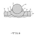
- FIG. 9 is an illustration depicting a cross-sectional view of the internal structure of the resulting weld area 62 after the two metals 60, 52 are joined using the direct resistance weld process of the present invention.
- a bond between the two metals is created when the lower melting temperature first metal 60 melts and wets the surface of the higher melting temperature second metal 52.
- the term wetting as defined herein is the ability of a liquid to maintain contact with a solid surface.
- the liquid first metal 60 (lower melting temperature metal) wets the solid surface of the second metal 52 (higher melting temperature metal).
- the bond is created between the surfaces of the first and second metals 60, 52 when the weld area 62 solidifies.
- an interface 80 is created between the first and second metals 60, 52.
- Interface 80 is the region of contact between the two metals. It is along this interface 80 that the first and second metals 60, 52 are joined together. Unlike other joining methods, an inter metallic bond wherein the first and second metals 60, 52 are mixed and coexist is not created during the resistance welding process of the present invention.
- the weld area 62 of the first metal 60 is comprised of three zones.
- the first zone is the fusion zone 74.
- the fusion zone 74 comprises the area surrounding the interface 80 between the two dissimilar metals.
- the first metal 60 has melted and wetted the surface of the second metal 52.
- the fusion zone 74 is most proximate the wetted second metal 52 surface.
- the fusion zone 74 extends distally from interface 80 into the body of the first metal 60.
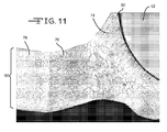
- FIGS. 10 and 11 are optical micrographs that show the internal structure of welding area 62.
- the micrographs show that the first metal 60 (lower melting temperature) in the fusion zone 74 lacks grain structure of a typical first metal not affected by temperature. This lack of grain structure is characteristic of a first metal 60 in the fusion zone 74. Instead, the first metal in the fusion zone 74, particularly near the interface 80 between the first and second metals 60, 52, appears columnar in shape.
- a columnar grain structure results when a grain grows faster in one direction than in other directions.
- a columnar grain structure as defined herein is a grain structure that appears to have small lines that radiate from interface 80 into the body of the first metal 60.
- This columnar grain appearance is indicative of the stresses that are created when extreme temperatures are applied to the surfaces of metals having extreme melting temperature differences over a short period of time, such as those conditions created during the resistance welding process of the current invention. Specifically, the columnar grain appearance is indicative of the rapid cooling and solidification along the elongated axis.
- the grain structure of the first metal 60 in the fusion zone 74 may appear to comprise two distinct grain structures.
- the first grain structure is that of columnar growth as previously mentioned.
- the second grain structure is that of very small grain sizes on the order of 0.1 micrometers or smaller depending on the first metal chosen. Viewing these small grain sizes may require the use of high powered magnification devices. These smaller second grain structures may be equiaxed. An equiaxed grain structure is one in which the length and width have similar dimensions.
- the heat generated by the welding process is sufficient to melt the first metal 60 in the fusion zone 74. After reaching its melting temperature, the first metal 60 begins to flow and wet the surface of the second metal. The second metal in the fusion zone 74 is not melted and acts as a barrier preventing flow of the melted first metal.
- Heat from the welding process is quickly removed from the area when current is turned off and the metallic bond solidifies. This short duration of time does not allow for the grain structure of the first metal 60 to reorient itself into its normal grain structure as illustrated in the unaffected base metal zone 78 ( FIG. 11 ). As a result, the first metal 60 quickly changes from a molten state to a solid state within a few milliseconds, thereby freezing the molten structure of the first metal 60 in the columnar grain structure shown.
- the second zone extends distally from the fusion zone 74.
- the heat affected zone (HAZ) 76 extends distally from the fusion zone 74.
- two discrete HAZ 76 areas extend distally from each fusion zone 74.
- One HAZ 76 extends to the left and the other HAZ 76 extends to the right of the central fusion zone 74.
- the HAZ 76 is indicative of a metal with grain sizes that are larger than those of the non-heat treated metal shown in base metal zone 78.
- the heat generated in the HAZ 76 is not sufficient to melt the first metal 60 in this zone, but the elevated temperature exposed in the HAZ 76 initiates re-crystallization and grain growth that results in a first metal with larger than normal grains. This is evident by the larger grain sizes shown in FIGS. 10 and 11 in the general area of the HAZ 76 in comparison to the base metal zone 78. It is typical that grains in the HAZ 76 increase to a size on the order of about 2 to about 10 times that of normal grains. For the aluminum metal example shown in FIG. 10 , grain sizes range from about 3 to about 5 micrometers in the HAZ 76. These larger grain sizes can also be observed in the micrograph shown in FIG. 11 which is a magnified view of the left side HAZ 76.
- the third zone, the base metal zone 78 is an area that extends distally from the HAZ 76 and is most distal the fusion zone 74.
- the base metal zone 78 is the area that is most distal from the heat of the resistance welding process and is, therefore, unaffected by the heat of the welding process of the present invention. As shown in the micrograph of FIG. 11 , this zone has metal that is of a normal grain structure typical of its initial state before welding. For the aluminum metal example shown in FIG. 11 , grain size is on the order of about 0.5 to about 2 micrometers.
- the black area at the bottom of FIGS. 10 and 11 is an image artifact from the sample mounting material. This black area is unrelated to the present invention and does not affect the resultant weld of the resistance weld process of the present invention.
- a primary electrochemical cell that possesses sufficient energy density and discharge capacity for the rigorous requirements of implantable medical devices comprises a lithium anode or its alloys, for example, Li-Si, Li-Al, Li-B and Li-Si-B.
- the form of the anode may vary, but preferably it is of a thin sheet or foil pressed or rolled on a metallic anode current collector 34.
- the cathode of a primary cell is of electrically conductive material, preferably a solid material.
- the solid cathode may comprise a metal element, a metal oxide, a mixed metal oxide and a metal sulfide, and combinations thereof.
- a preferred cathode active material is selected from the group consisting of silver vanadium oxide, copper silver vanadium oxide, manganese dioxide, cobalt nickel, nickel oxide, copper oxide, copper sulfide, iron sulfide, iron disulfide, titanium disulfide, copper vanadium oxide, and mixtures thereof.
- the cathode active material is mixed with a binder material such as a powdered fluoro-polymer, more preferably powdered polytetrafluoroethylene or powdered polyvinylidene fluoride present at about 1 to about 5 weight percent of the cathode mixture.
- a binder material such as a powdered fluoro-polymer, more preferably powdered polytetrafluoroethylene or powdered polyvinylidene fluoride present at about 1 to about 5 weight percent of the cathode mixture.
- a conductive diluent is preferably added to the cathode mixture to improve conductivity.
- Suitable materials for this purpose include acetylene black, carbon black and/or graphite or a metallic powder such as powdered nickel, aluminum, titanium and stainless steel.
- the preferred cathode active mixture thus includes a powdered fluoro-polymer binder present at about 3 weight percent, a conductive diluent present at
- the cathode component 38, 40 may be prepared by rolling, spreading or pressing the cathode active mixture onto a suitable cathode current collector 34.
- Cathodes prepared as described are preferably in the form of a strip wound with a corresponding strip of anode material in a structure similar to a "jellyroll" or a flat-folded electrode stack, such as that illustrated in FIG. 6 .
- the separator membrane 54 is preferably made of a fabric woven from fluoropolymeric fibers including polyvinylidine fluoride, polyethylenetetrafluoroethylene, and polyethylenechlorotrifluoroethylene used either alone or laminated with a fluoropolymeric microporous film, non-woven glass, polypropylene, polyethylene, glass fiber materials, ceramics, polytetrafluoroethylene membrane commercially available under the designation ZITEX (Chemplast Inc.), polypropylene membrane commercially available under the designation CELGARD (Celanese Plastic Company, Inc.) and a membrane commercially available under the designation DEXIGLAS (C. H. Dexter, Div., Dexter Corp.).
- fluoropolymeric fibers including polyvinylidine fluoride, polyethylenetetrafluoroethylene, and polyethylenechlorotrifluoroethylene used either alone or laminated with a fluoropolymeric microporous film, non-woven glass, polypropylene, polyethylene
- a primary electrochemical cell includes a nonaqueous, ionically conductive electrolyte having an inorganic, ionically conductive salt dissolved in a nonaqueous solvent and, more preferably, a lithium salt dissolved in a mixture of a low viscosity solvent and a high permittivity solvent.
- the salt serves as the vehicle for migration of the anode ions to intercalate or react with the cathode active material and suitable salts include LiPF 6 , LiBF 4 , LiAsF 6 , LiSbF 6 , LiClO 4 , LiO 2 , LiAlCl 4 , LiGaCl 4 , LiC(SO 2 CF 3 ) 3 , LiN(SO 2 CF 3 ) 2 , LiSCN, LiO 3 SCF 3 , LiC 6 F 5 SO 3 , LiO 2 CCF 3 , LiSO 6 F, LiB(C 6 H 5 ) 4 , LiCF 3 SO 3 , and mixtures thereof.
- suitable salts include LiPF 6 , LiBF 4 , LiAsF 6 , LiSbF 6 , LiClO 4 , LiO 2 , LiAlCl 4 , LiGaCl 4 , LiC(SO 2 CF 3 ) 3 , LiN(SO 2 CF 3 ) 2 ,
- Suitable low viscosity solvents include esters, linear and cyclic ethers and dialkyl carbonates such as tetrahydrofuran (THF), methyl acetate (MA), diglyme, trigylme, tetragylme, dimethyl carbonate (DMC), 1,2-dimethoxyethane (DME), 1,2-diethoxyethane (DEE), 1-ethoxy,2-methoxyethane (EME), ethyl methyl carbonate, methyl propyl carbonate, ethyl propyl carbonate, diethyl carbonate, dipropyl carbonate, and mixtures thereof.
- THF tetrahydrofuran
- MA methyl acetate
- DMC 1,2-dimethoxyethane
- DEE 1,2-diethoxyethane
- EME 1-ethoxy,2-methoxyethane
- ethyl methyl carbonate methyl propyl carbonate, ethyl propyl carbon
- High permittivity solvents include cyclic carbonates, cyclic esters and cyclic amides such as propylene carbonate (PC), ethylene carbonate (EC), butylene carbonate, acetonitrile, dimethyl sulfoxide, dimethyl, formamide, dimethyl acetamide, ⁇ -valerolactone, ⁇ -butyrolactone (GBL), N-methyl-pyrrolidinone (NMP), and mixtures thereof.
- the preferred electrolyte for a lithium primary cell is 0.8M to 1.5M LiAsF 6 or LiPF 6 dissolved in a 50:50 mixture, by volume, of PC as the preferred high permittivity solvent and DME as the preferred low viscosity solvent.
- the active material of cathode body is silver vanadium oxide as described in U.S. Pat. Nos. 4,310,609 and 4,391,729 to Liang et al. , or copper silver vanadium oxide as described in U.S. Pat. Nos. 5,472,810 and 5,516,340 to Takeuchi et al. , all assigned to the assignee of the present invention, the disclosures of which are hereby incorporated by reference.
- the anode electrode 42, 44 comprises a material capable of intercalating and deintercalating the alkali metal, and preferably lithium.
- a carbonaceous anode comprising any of the various forms of carbon (e.g., coke, graphite, acetylene black, carbon black, glassy carbon, etc.), which are capable of reversibly retaining the lithium species, is preferred.
- Graphite is particularly preferred due to its relatively high lithium-retention capacity.
- fibers of the carbonaceous material are particularly advantageous because they have excellent mechanical properties that permit them to be fabricated into rigid electrodes capable of withstanding degradation during repeated charge/discharge cycling.
- the cathode electrode 38, 40 of a secondary cell preferably comprises a lithiated material that is stable in air and readily handled.
- air-stable lithiated cathode materials include oxides, sulfides, selenides, and tellurides of such metals as vanadium, titanium, chromium, copper, molybdenum, niobium, iron, nickel, cobalt and manganese.
- the more preferred oxides include LiNiO 2 , LiMn 2 O 4 , LiCoO 2 , LiCo 0.92 Sn 0.08 O 2 and LiCO 1-x Ni x O 2 .
- the lithiated active material is preferably mixed with a conductive additive selected from acetylene black, carbon black, graphite, and powdered metals of nickel, aluminum, titanium and stainless steel.
- the electrode further comprises a fluoro-resin binder, preferably in a powder form, such as PTFE, PVDF, ETFE, polyamides and polyimides, and mixtures thereof.
- the current collector 33, 34 is selected from stainless steel, titanium, tantalum, platinum, gold, aluminum, cobalt nickel alloys, highly alloyed ferritic stainless steel containing molybdenum and chromium, and nickel-, chromium- and molybdenum-containing alloys.
- Suitable secondary electrochemical systems are comprised of nonaqueous electrolytes of an inorganic salt dissolved in a nonaqueous solvent and more preferably an alkali metal salt dissolved in a quaternary mixture of organic carbonate solvents comprising dialkyl (non-cyclic) carbonates selected from dimethyl carbonate (DMC), diethyl carbonate (DEC), dipropyl carbonate (DPC), ethyl methyl carbonate (EMC), methyl propyl carbonate (MPC) and ethyl propyl carbonate (EPC), and mixtures thereof, and at least one cyclic carbonate selected from propylene carbonate (PC), ethylene carbonate (EC), butylene carbonate (BC) and vinylene carbonate (VC), and mixtures thereof.
- Organic carbonates are generally used in the electrolyte solvent system for such battery chemistries because they exhibit high oxidative stability toward cathode materials and good kinetic stability toward anode materials.
- a preferred material for the casing is titanium although stainless steel, mild steel, nickel-plated mild steel and aluminum are also suitable.
- the casing header comprises a metallic lid having an opening to accommodate the glass-to-metal seal/terminal pin feedthrough for the cathode electrode.
- the anode electrode or counter electrode is preferably connected to the case or the lid.
- An additional opening is provided for electrolyte filling.
- the casing header comprises elements having compatibility with the other components of the electrochemical cell and is resistant to corrosion. The cell is thereafter filled with the electrolyte solution described hereinabove and hermetically sealed such as by close-welding a titanium plug over the fill hole, but not limited thereto.
Landscapes
- Chemical & Material Sciences (AREA)
- Chemical Kinetics & Catalysis (AREA)
- Electrochemistry (AREA)
- General Chemical & Material Sciences (AREA)
- Engineering & Computer Science (AREA)
- Manufacturing & Machinery (AREA)
- Mechanical Engineering (AREA)
- Connection Of Batteries Or Terminals (AREA)
Applications Claiming Priority (2)
| Application Number | Priority Date | Filing Date | Title |
|---|---|---|---|
| US26365909P | 2009-11-23 | 2009-11-23 | |
| US12/944,859 US8722238B2 (en) | 2009-11-23 | 2010-11-12 | Direct resistance welding—self brazing of aluminum to molybdenum pin |
Publications (3)
| Publication Number | Publication Date |
|---|---|
| EP2325928A2 true EP2325928A2 (de) | 2011-05-25 |
| EP2325928A3 EP2325928A3 (de) | 2011-07-27 |
| EP2325928B1 EP2325928B1 (de) | 2018-03-28 |
Family
ID=43598149
Family Applications (1)
| Application Number | Title | Priority Date | Filing Date |
|---|---|---|---|
| EP10192075.9A Not-in-force EP2325928B1 (de) | 2009-11-23 | 2010-11-22 | Direktwiderstandsschweißen - Selbsthartlötung von Aluminium- zu Molybdenum-Stiften |
Country Status (2)
| Country | Link |
|---|---|
| US (3) | US8722238B2 (de) |
| EP (1) | EP2325928B1 (de) |
Cited By (4)
| Publication number | Priority date | Publication date | Assignee | Title |
|---|---|---|---|---|
| US8722238B2 (en) | 2009-11-23 | 2014-05-13 | Greatbatch Ltd. | Direct resistance welding—self brazing of aluminum to molybdenum pin |
| US9300007B1 (en) | 2011-01-07 | 2016-03-29 | Greatbatch Ltd. | Ultrasonic welding of lithium onto a current collector |
| US10118245B2 (en) | 2013-10-11 | 2018-11-06 | Greatbatch Ltd. | Sacrificial resistance weld electrode |
| US10205151B2 (en) | 2012-04-20 | 2019-02-12 | Greatbatch Ltd. | Connector from the tab of an electrode current collector to the terminal pin of a feedthrough in an electrochemical cell |
Families Citing this family (6)
| Publication number | Priority date | Publication date | Assignee | Title |
|---|---|---|---|---|
| US10818890B2 (en) | 2014-04-22 | 2020-10-27 | Medtronic, Inc. | Power source for an implantable medical device |
| US11130197B2 (en) | 2017-11-03 | 2021-09-28 | Greatbatch Ltd. | Laser brazed component and method therefor |
| US10874865B2 (en) | 2017-11-06 | 2020-12-29 | Avx Corporation | EMI feedthrough filter terminal assembly containing a resin coating over a hermetically sealing material |
| US11831030B2 (en) * | 2018-05-22 | 2023-11-28 | Pacesetter, Inc. | Method of forming a brazed joint having molybdenum material |
| US10734348B2 (en) * | 2018-09-21 | 2020-08-04 | Taiwan Semiconductor Manufacturing Company, Ltd. | Bonded semiconductor devices and methods of forming the same |
| CN118830097A (zh) * | 2022-03-16 | 2024-10-22 | 松下知识产权经营株式会社 | 制造装置 |
Citations (6)
| Publication number | Priority date | Publication date | Assignee | Title |
|---|---|---|---|---|
| US4310609A (en) | 1979-12-17 | 1982-01-12 | Wilson Greatbatch Ltd. | Metal oxide composite cathode material for high energy density batteries |
| US4391729A (en) | 1979-12-17 | 1983-07-05 | Wilson Greatbatch Ltd. | Metal oxide composite cathode material for high energy density batteries |
| US5250373A (en) | 1991-09-10 | 1993-10-05 | Wilson Greatbatch Ltd. | Internal electrode and assembly method for electrochemical cells |
| US5472810A (en) | 1993-03-17 | 1995-12-05 | W. Greatbatch Ltd. | Copper, silver, vanadium oxide composite cathode material for high energy density batteries |
| US5516340A (en) | 1993-03-17 | 1996-05-14 | Wilson Greatbatch Ltd. | Process for making a metal oxide composite cathode material for high energy density batteries |
| US6929881B2 (en) | 2001-07-30 | 2005-08-16 | Wilson Greatbatch Technologies, Inc. | Connection for joining a current collector to a terminal pin for a primary lithium or secondary lithium ion electrochemical cell |
Family Cites Families (22)
| Publication number | Priority date | Publication date | Assignee | Title |
|---|---|---|---|---|
| US4252263A (en) | 1980-04-11 | 1981-02-24 | General Electric Company | Method and apparatus for thermo-compression diffusion bonding |
| US4761355A (en) | 1980-11-24 | 1988-08-02 | Medtronic, Inc. | Electrochemical cells and cathode materials |
| US4865932A (en) | 1987-05-12 | 1989-09-12 | Bridgestone Corporation | Electric cells and process for making the same |
| US5354629A (en) | 1991-10-09 | 1994-10-11 | Sanyo Electric Co., Ltd. | Monaqueous electrolyte battery |
| US5786559A (en) * | 1995-10-17 | 1998-07-28 | Meyer Tool, Inc. | Weld-braze process |
| US5571146A (en) | 1995-10-31 | 1996-11-05 | Pacesetter, Inc. | Technique for welding dissimilar metals |
| US5750286A (en) | 1996-07-31 | 1998-05-12 | Wilson Greatbatch Ltd. | Dual connection tab current collector |
| US6190426B1 (en) | 1998-12-17 | 2001-02-20 | Moltech Corporation | Methods of preparing prismatic cells |
| WO2001039294A2 (en) | 1999-11-23 | 2001-05-31 | Moltech Corporation | Methods of preparing electrochemical cells |
| US6503640B2 (en) | 2000-05-19 | 2003-01-07 | Corus Aluminium Walzeprodukte Gmbh | Method of manufacturing an assembly of brazed dissimilar metal components |
| KR100890715B1 (ko) | 2000-11-01 | 2009-03-27 | 소니 가부시끼 가이샤 | 전지, 전지의 제조 방법, 용접물의 제조 방법 및 페데스탈 |
| CN100406190C (zh) * | 2001-11-02 | 2008-07-30 | 波音公司 | 形成具有残余压应力分布形式的焊接接头的装置和方法 |
| US20040038070A1 (en) | 2001-11-21 | 2004-02-26 | Dockus Kostas F. | Fluxless brazing |
| US7108942B1 (en) | 2003-03-27 | 2006-09-19 | Wilson Greatbatch Technologies, Inc. | Efficient electrode assembly design for cells with alkali metal anodes |
| US7341802B1 (en) | 2004-03-25 | 2008-03-11 | Quallion Llc | Feedthrough assembly and method |
| EP1814189A4 (de) | 2004-10-27 | 2009-04-15 | Panasonic Corp | Batteriepack |
| US7749651B2 (en) | 2005-11-28 | 2010-07-06 | Greatbatch Ltd. | Terminal connector for connecting an electrochemical cell to a medical device |
| US7539007B2 (en) | 2005-12-29 | 2009-05-26 | Medtronic, Inc. | Methods and structures for electrically coupling a conductor and a conductive element comprising a dissimilar material |
| JP5054419B2 (ja) | 2006-07-06 | 2012-10-24 | エナックス株式会社 | シート状二次電池 |
| JP4991581B2 (ja) | 2008-01-22 | 2012-08-01 | ソニー株式会社 | バッテリパック及び配線基板 |
| US20110104520A1 (en) | 2009-11-02 | 2011-05-05 | Changbum Ahn | Secondary battery and battery pack using the same |
| US8722238B2 (en) | 2009-11-23 | 2014-05-13 | Greatbatch Ltd. | Direct resistance welding—self brazing of aluminum to molybdenum pin |
-
2010
- 2010-11-12 US US12/944,859 patent/US8722238B2/en not_active Expired - Fee Related
- 2010-11-22 EP EP10192075.9A patent/EP2325928B1/de not_active Not-in-force
-
2014
- 2014-05-13 US US14/276,798 patent/US9722258B2/en not_active Expired - Fee Related
- 2014-05-13 US US14/276,961 patent/US20140246408A1/en not_active Abandoned
Patent Citations (6)
| Publication number | Priority date | Publication date | Assignee | Title |
|---|---|---|---|---|
| US4310609A (en) | 1979-12-17 | 1982-01-12 | Wilson Greatbatch Ltd. | Metal oxide composite cathode material for high energy density batteries |
| US4391729A (en) | 1979-12-17 | 1983-07-05 | Wilson Greatbatch Ltd. | Metal oxide composite cathode material for high energy density batteries |
| US5250373A (en) | 1991-09-10 | 1993-10-05 | Wilson Greatbatch Ltd. | Internal electrode and assembly method for electrochemical cells |
| US5472810A (en) | 1993-03-17 | 1995-12-05 | W. Greatbatch Ltd. | Copper, silver, vanadium oxide composite cathode material for high energy density batteries |
| US5516340A (en) | 1993-03-17 | 1996-05-14 | Wilson Greatbatch Ltd. | Process for making a metal oxide composite cathode material for high energy density batteries |
| US6929881B2 (en) | 2001-07-30 | 2005-08-16 | Wilson Greatbatch Technologies, Inc. | Connection for joining a current collector to a terminal pin for a primary lithium or secondary lithium ion electrochemical cell |
Cited By (5)
| Publication number | Priority date | Publication date | Assignee | Title |
|---|---|---|---|---|
| US8722238B2 (en) | 2009-11-23 | 2014-05-13 | Greatbatch Ltd. | Direct resistance welding—self brazing of aluminum to molybdenum pin |
| US9722258B2 (en) | 2009-11-23 | 2017-08-01 | Greatbatch Ltd. | Method of direct resistance welding—self brazing of aluminum to molybdenum pin |
| US9300007B1 (en) | 2011-01-07 | 2016-03-29 | Greatbatch Ltd. | Ultrasonic welding of lithium onto a current collector |
| US10205151B2 (en) | 2012-04-20 | 2019-02-12 | Greatbatch Ltd. | Connector from the tab of an electrode current collector to the terminal pin of a feedthrough in an electrochemical cell |
| US10118245B2 (en) | 2013-10-11 | 2018-11-06 | Greatbatch Ltd. | Sacrificial resistance weld electrode |
Also Published As
| Publication number | Publication date |
|---|---|
| US8722238B2 (en) | 2014-05-13 |
| US20140245600A1 (en) | 2014-09-04 |
| US9722258B2 (en) | 2017-08-01 |
| EP2325928A3 (de) | 2011-07-27 |
| EP2325928B1 (de) | 2018-03-28 |
| US20140246408A1 (en) | 2014-09-04 |
| US20110123856A1 (en) | 2011-05-26 |
Similar Documents
| Publication | Publication Date | Title |
|---|---|---|
| EP2325928B1 (de) | Direktwiderstandsschweißen - Selbsthartlötung von Aluminium- zu Molybdenum-Stiften | |
| US10170744B2 (en) | Electrochemical current collector screen designs utilizing ultrasonic welding | |
| EP1282178B1 (de) | Kupplung zwischen Stromkollektor und Endpol für primäre oder sekundäre Lithiumbatterie | |
| US6537698B2 (en) | Electrochemical cell having an electrode with a phosphonate additive in the electrode active mixture | |
| US10916740B2 (en) | Method of providing an electrochemical cell casing having an open-ended main body portion of grade 5 or 23 titanium closed by upper and lower lids of grade 1 or 2 titanium | |
| US20120282519A1 (en) | Dissimilar Material Battery Enclosure for Improved Weld Structure | |
| EP3614461B1 (de) | Eine übertragbare elektrodenspitze zum widerstandsschweissen einer anodenlasche am gehäuse einer elektrochemischen zelle | |
| US10205151B2 (en) | Connector from the tab of an electrode current collector to the terminal pin of a feedthrough in an electrochemical cell | |
| US9553296B1 (en) | Magnetic pulse welding in medical power manufacturing | |
| US11670816B2 (en) | Glass-to-metal seal terminal pin for an electrochemical cell | |
| EP1244160A1 (de) | Elektrochemische Zelle mit einer Elektrode umfassend Karbonate als Zusatz für die active Mischung der Elektrode | |
| US9300007B1 (en) | Ultrasonic welding of lithium onto a current collector | |
| EP1318555B1 (de) | Positive Elektrodenanordnung mit doppeltem Stromkollektor für elektrochemische Alkalimetallionen-Zellen | |
| US12095102B2 (en) | Co-axial glass-to-metal seal feedthrough for a case-neutral electrochemical cell | |
| US20160271728A1 (en) | Laser welding-self brazing in medical power manufacturing | |
| US11355820B2 (en) | Transferable electrode tip for resistance welding an anode tab to the casing of an electrochemical cell | |
| US12261309B2 (en) | Co-axial glass-to-metal seal for a case-neutral electrochemical cell | |
| US12249726B2 (en) | Method for manufacturing a co-axial glass-to-metal seal for a case-neutral electrochemical cell | |
| US12142775B1 (en) | Method for manufacturing a co-axial glass-to-metal seal feedthrough for a case-neutral electrochemical cell | |
| EP4307409A1 (de) | Elastomerdichtung zur kontaktierung der innenfläche des gehäusedeckels einer pulsentladbaren elektrochemischen lithiumzelle | |
| EP4683054A1 (de) | Elektrochemische zelle und verfahren zu ihrer herstellung | |
| EP4164007A1 (de) | Sekundäre elektrochemische miniaturzelle mit stromkollektor zur verbesserung der leerlaufspannung |
Legal Events
| Date | Code | Title | Description |
|---|---|---|---|
| PUAI | Public reference made under article 153(3) epc to a published international application that has entered the european phase |
Free format text: ORIGINAL CODE: 0009012 |
|
| AK | Designated contracting states |
Kind code of ref document: A2 Designated state(s): AL AT BE BG CH CY CZ DE DK EE ES FI FR GB GR HR HU IE IS IT LI LT LU LV MC MK MT NL NO PL PT RO RS SE SI SK SM TR |
|
| AX | Request for extension of the european patent |
Extension state: BA ME |
|
| PUAL | Search report despatched |
Free format text: ORIGINAL CODE: 0009013 |
|
| AK | Designated contracting states |
Kind code of ref document: A3 Designated state(s): AL AT BE BG CH CY CZ DE DK EE ES FI FR GB GR HR HU IE IS IT LI LT LU LV MC MK MT NL NO PL PT RO RS SE SI SK SM TR |
|
| AX | Request for extension of the european patent |
Extension state: BA ME |
|
| 17P | Request for examination filed |
Effective date: 20120126 |
|
| 17Q | First examination report despatched |
Effective date: 20150422 |
|
| RIC1 | Information provided on ipc code assigned before grant |
Ipc: B23K 11/00 20060101ALI20170406BHEP Ipc: H01M 2/22 20060101AFI20170406BHEP Ipc: H01M 6/00 20060101ALI20170406BHEP |
|
| GRAP | Despatch of communication of intention to grant a patent |
Free format text: ORIGINAL CODE: EPIDOSNIGR1 |
|
| INTG | Intention to grant announced |
Effective date: 20170526 |
|
| GRAS | Grant fee paid |
Free format text: ORIGINAL CODE: EPIDOSNIGR3 |
|
| GRAJ | Information related to disapproval of communication of intention to grant by the applicant or resumption of examination proceedings by the epo deleted |
Free format text: ORIGINAL CODE: EPIDOSDIGR1 |
|
| GRAL | Information related to payment of fee for publishing/printing deleted |
Free format text: ORIGINAL CODE: EPIDOSDIGR3 |
|
| INTC | Intention to grant announced (deleted) | ||
| GRAR | Information related to intention to grant a patent recorded |
Free format text: ORIGINAL CODE: EPIDOSNIGR71 |
|
| GRAA | (expected) grant |
Free format text: ORIGINAL CODE: 0009210 |
|
| AK | Designated contracting states |
Kind code of ref document: B1 Designated state(s): AL AT BE BG CH CY CZ DE DK EE ES FI FR GB GR HR HU IE IS IT LI LT LU LV MC MK MT NL NO PL PT RO RS SE SI SK SM TR |
|
| INTG | Intention to grant announced |
Effective date: 20180220 |
|
| REG | Reference to a national code |
Ref country code: GB Ref legal event code: FG4D |
|
| REG | Reference to a national code |
Ref country code: CH Ref legal event code: EP |
|
| REG | Reference to a national code |
Ref country code: AT Ref legal event code: REF Ref document number: 984164 Country of ref document: AT Kind code of ref document: T Effective date: 20180415 |
|
| REG | Reference to a national code |
Ref country code: IE Ref legal event code: FG4D |
|
| REG | Reference to a national code |
Ref country code: DE Ref legal event code: R096 Ref document number: 602010049463 Country of ref document: DE |
|
| PG25 | Lapsed in a contracting state [announced via postgrant information from national office to epo] |
Ref country code: NO Free format text: LAPSE BECAUSE OF FAILURE TO SUBMIT A TRANSLATION OF THE DESCRIPTION OR TO PAY THE FEE WITHIN THE PRESCRIBED TIME-LIMIT Effective date: 20180628 Ref country code: HR Free format text: LAPSE BECAUSE OF FAILURE TO SUBMIT A TRANSLATION OF THE DESCRIPTION OR TO PAY THE FEE WITHIN THE PRESCRIBED TIME-LIMIT Effective date: 20180328 Ref country code: LT Free format text: LAPSE BECAUSE OF FAILURE TO SUBMIT A TRANSLATION OF THE DESCRIPTION OR TO PAY THE FEE WITHIN THE PRESCRIBED TIME-LIMIT Effective date: 20180328 Ref country code: FI Free format text: LAPSE BECAUSE OF FAILURE TO SUBMIT A TRANSLATION OF THE DESCRIPTION OR TO PAY THE FEE WITHIN THE PRESCRIBED TIME-LIMIT Effective date: 20180328 |
|
| REG | Reference to a national code |
Ref country code: NL Ref legal event code: MP Effective date: 20180328 |
|
| REG | Reference to a national code |
Ref country code: LT Ref legal event code: MG4D |
|
| PG25 | Lapsed in a contracting state [announced via postgrant information from national office to epo] |
Ref country code: RS Free format text: LAPSE BECAUSE OF FAILURE TO SUBMIT A TRANSLATION OF THE DESCRIPTION OR TO PAY THE FEE WITHIN THE PRESCRIBED TIME-LIMIT Effective date: 20180328 Ref country code: GR Free format text: LAPSE BECAUSE OF FAILURE TO SUBMIT A TRANSLATION OF THE DESCRIPTION OR TO PAY THE FEE WITHIN THE PRESCRIBED TIME-LIMIT Effective date: 20180629 Ref country code: BG Free format text: LAPSE BECAUSE OF FAILURE TO SUBMIT A TRANSLATION OF THE DESCRIPTION OR TO PAY THE FEE WITHIN THE PRESCRIBED TIME-LIMIT Effective date: 20180628 Ref country code: SE Free format text: LAPSE BECAUSE OF FAILURE TO SUBMIT A TRANSLATION OF THE DESCRIPTION OR TO PAY THE FEE WITHIN THE PRESCRIBED TIME-LIMIT Effective date: 20180328 Ref country code: LV Free format text: LAPSE BECAUSE OF FAILURE TO SUBMIT A TRANSLATION OF THE DESCRIPTION OR TO PAY THE FEE WITHIN THE PRESCRIBED TIME-LIMIT Effective date: 20180328 |
|
| REG | Reference to a national code |
Ref country code: FR Ref legal event code: PLFP Year of fee payment: 9 |
|
| PG25 | Lapsed in a contracting state [announced via postgrant information from national office to epo] |
Ref country code: NL Free format text: LAPSE BECAUSE OF FAILURE TO SUBMIT A TRANSLATION OF THE DESCRIPTION OR TO PAY THE FEE WITHIN THE PRESCRIBED TIME-LIMIT Effective date: 20180328 Ref country code: AL Free format text: LAPSE BECAUSE OF FAILURE TO SUBMIT A TRANSLATION OF THE DESCRIPTION OR TO PAY THE FEE WITHIN THE PRESCRIBED TIME-LIMIT Effective date: 20180328 Ref country code: ES Free format text: LAPSE BECAUSE OF FAILURE TO SUBMIT A TRANSLATION OF THE DESCRIPTION OR TO PAY THE FEE WITHIN THE PRESCRIBED TIME-LIMIT Effective date: 20180328 Ref country code: PL Free format text: LAPSE BECAUSE OF FAILURE TO SUBMIT A TRANSLATION OF THE DESCRIPTION OR TO PAY THE FEE WITHIN THE PRESCRIBED TIME-LIMIT Effective date: 20180328 Ref country code: IT Free format text: LAPSE BECAUSE OF FAILURE TO SUBMIT A TRANSLATION OF THE DESCRIPTION OR TO PAY THE FEE WITHIN THE PRESCRIBED TIME-LIMIT Effective date: 20180328 Ref country code: RO Free format text: LAPSE BECAUSE OF FAILURE TO SUBMIT A TRANSLATION OF THE DESCRIPTION OR TO PAY THE FEE WITHIN THE PRESCRIBED TIME-LIMIT Effective date: 20180328 Ref country code: EE Free format text: LAPSE BECAUSE OF FAILURE TO SUBMIT A TRANSLATION OF THE DESCRIPTION OR TO PAY THE FEE WITHIN THE PRESCRIBED TIME-LIMIT Effective date: 20180328 |
|
| PG25 | Lapsed in a contracting state [announced via postgrant information from national office to epo] |
Ref country code: SK Free format text: LAPSE BECAUSE OF FAILURE TO SUBMIT A TRANSLATION OF THE DESCRIPTION OR TO PAY THE FEE WITHIN THE PRESCRIBED TIME-LIMIT Effective date: 20180328 Ref country code: CZ Free format text: LAPSE BECAUSE OF FAILURE TO SUBMIT A TRANSLATION OF THE DESCRIPTION OR TO PAY THE FEE WITHIN THE PRESCRIBED TIME-LIMIT Effective date: 20180328 Ref country code: SM Free format text: LAPSE BECAUSE OF FAILURE TO SUBMIT A TRANSLATION OF THE DESCRIPTION OR TO PAY THE FEE WITHIN THE PRESCRIBED TIME-LIMIT Effective date: 20180328 |
|
| REG | Reference to a national code |
Ref country code: AT Ref legal event code: MK05 Ref document number: 984164 Country of ref document: AT Kind code of ref document: T Effective date: 20180328 |
|
| PG25 | Lapsed in a contracting state [announced via postgrant information from national office to epo] |
Ref country code: PT Free format text: LAPSE BECAUSE OF FAILURE TO SUBMIT A TRANSLATION OF THE DESCRIPTION OR TO PAY THE FEE WITHIN THE PRESCRIBED TIME-LIMIT Effective date: 20180730 |
|
| REG | Reference to a national code |
Ref country code: DE Ref legal event code: R097 Ref document number: 602010049463 Country of ref document: DE |
|
| PG25 | Lapsed in a contracting state [announced via postgrant information from national office to epo] |
Ref country code: AT Free format text: LAPSE BECAUSE OF FAILURE TO SUBMIT A TRANSLATION OF THE DESCRIPTION OR TO PAY THE FEE WITHIN THE PRESCRIBED TIME-LIMIT Effective date: 20180328 Ref country code: DK Free format text: LAPSE BECAUSE OF FAILURE TO SUBMIT A TRANSLATION OF THE DESCRIPTION OR TO PAY THE FEE WITHIN THE PRESCRIBED TIME-LIMIT Effective date: 20180328 |
|
| PGFP | Annual fee paid to national office [announced via postgrant information from national office to epo] |
Ref country code: DE Payment date: 20181106 Year of fee payment: 9 |
|
| PLBE | No opposition filed within time limit |
Free format text: ORIGINAL CODE: 0009261 |
|
| STAA | Information on the status of an ep patent application or granted ep patent |
Free format text: STATUS: NO OPPOSITION FILED WITHIN TIME LIMIT |
|
| PGFP | Annual fee paid to national office [announced via postgrant information from national office to epo] |
Ref country code: FR Payment date: 20181011 Year of fee payment: 9 |
|
| 26N | No opposition filed |
Effective date: 20190103 |
|
| PG25 | Lapsed in a contracting state [announced via postgrant information from national office to epo] |
Ref country code: SI Free format text: LAPSE BECAUSE OF FAILURE TO SUBMIT A TRANSLATION OF THE DESCRIPTION OR TO PAY THE FEE WITHIN THE PRESCRIBED TIME-LIMIT Effective date: 20180328 |
|
| REG | Reference to a national code |
Ref country code: CH Ref legal event code: PL |
|
| GBPC | Gb: european patent ceased through non-payment of renewal fee |
Effective date: 20181122 |
|
| PG25 | Lapsed in a contracting state [announced via postgrant information from national office to epo] |
Ref country code: LU Free format text: LAPSE BECAUSE OF NON-PAYMENT OF DUE FEES Effective date: 20181122 Ref country code: MC Free format text: LAPSE BECAUSE OF FAILURE TO SUBMIT A TRANSLATION OF THE DESCRIPTION OR TO PAY THE FEE WITHIN THE PRESCRIBED TIME-LIMIT Effective date: 20180328 |
|
| REG | Reference to a national code |
Ref country code: BE Ref legal event code: MM Effective date: 20181130 |
|
| REG | Reference to a national code |
Ref country code: IE Ref legal event code: MM4A |
|
| PG25 | Lapsed in a contracting state [announced via postgrant information from national office to epo] |
Ref country code: LI Free format text: LAPSE BECAUSE OF NON-PAYMENT OF DUE FEES Effective date: 20181130 Ref country code: CH Free format text: LAPSE BECAUSE OF NON-PAYMENT OF DUE FEES Effective date: 20181130 |
|
| PG25 | Lapsed in a contracting state [announced via postgrant information from national office to epo] |
Ref country code: IE Free format text: LAPSE BECAUSE OF NON-PAYMENT OF DUE FEES Effective date: 20181122 |
|
| PG25 | Lapsed in a contracting state [announced via postgrant information from national office to epo] |
Ref country code: BE Free format text: LAPSE BECAUSE OF NON-PAYMENT OF DUE FEES Effective date: 20181130 |
|
| PG25 | Lapsed in a contracting state [announced via postgrant information from national office to epo] |
Ref country code: GB Free format text: LAPSE BECAUSE OF NON-PAYMENT OF DUE FEES Effective date: 20181122 |
|
| PG25 | Lapsed in a contracting state [announced via postgrant information from national office to epo] |
Ref country code: MT Free format text: LAPSE BECAUSE OF NON-PAYMENT OF DUE FEES Effective date: 20181122 |
|
| PG25 | Lapsed in a contracting state [announced via postgrant information from national office to epo] |
Ref country code: TR Free format text: LAPSE BECAUSE OF FAILURE TO SUBMIT A TRANSLATION OF THE DESCRIPTION OR TO PAY THE FEE WITHIN THE PRESCRIBED TIME-LIMIT Effective date: 20180328 |
|
| REG | Reference to a national code |
Ref country code: DE Ref legal event code: R119 Ref document number: 602010049463 Country of ref document: DE |
|
| PG25 | Lapsed in a contracting state [announced via postgrant information from national office to epo] |
Ref country code: HU Free format text: LAPSE BECAUSE OF FAILURE TO SUBMIT A TRANSLATION OF THE DESCRIPTION OR TO PAY THE FEE WITHIN THE PRESCRIBED TIME-LIMIT; INVALID AB INITIO Effective date: 20101122 Ref country code: CY Free format text: LAPSE BECAUSE OF FAILURE TO SUBMIT A TRANSLATION OF THE DESCRIPTION OR TO PAY THE FEE WITHIN THE PRESCRIBED TIME-LIMIT Effective date: 20180328 Ref country code: MK Free format text: LAPSE BECAUSE OF NON-PAYMENT OF DUE FEES Effective date: 20180328 |
|
| PG25 | Lapsed in a contracting state [announced via postgrant information from national office to epo] |
Ref country code: IS Free format text: LAPSE BECAUSE OF FAILURE TO SUBMIT A TRANSLATION OF THE DESCRIPTION OR TO PAY THE FEE WITHIN THE PRESCRIBED TIME-LIMIT Effective date: 20180728 |
|
| PG25 | Lapsed in a contracting state [announced via postgrant information from national office to epo] |
Ref country code: FR Free format text: LAPSE BECAUSE OF NON-PAYMENT OF DUE FEES Effective date: 20191130 Ref country code: DE Free format text: LAPSE BECAUSE OF NON-PAYMENT OF DUE FEES Effective date: 20200603 |