EP2325880A2 - Immersion cooling apparatus for a power semiconductor device - Google Patents
Immersion cooling apparatus for a power semiconductor device Download PDFInfo
- Publication number
- EP2325880A2 EP2325880A2 EP10191187A EP10191187A EP2325880A2 EP 2325880 A2 EP2325880 A2 EP 2325880A2 EP 10191187 A EP10191187 A EP 10191187A EP 10191187 A EP10191187 A EP 10191187A EP 2325880 A2 EP2325880 A2 EP 2325880A2
- Authority
- EP
- European Patent Office
- Prior art keywords
- thermally conductive
- housing
- chamber
- conductive module
- cooling apparatus
- Prior art date
- Legal status (The legal status is an assumption and is not a legal conclusion. Google has not performed a legal analysis and makes no representation as to the accuracy of the status listed.)
- Withdrawn
Links
Images


Classifications
-
- H—ELECTRICITY
- H10—SEMICONDUCTOR DEVICES; ELECTRIC SOLID-STATE DEVICES NOT OTHERWISE PROVIDED FOR
- H10W—GENERIC PACKAGES, INTERCONNECTIONS, CONNECTORS OR OTHER CONSTRUCTIONAL DETAILS OF DEVICES COVERED BY CLASS H10
- H10W40/00—Arrangements for thermal protection or thermal control
- H10W40/70—Fillings or auxiliary members in containers or in encapsulations for thermal protection or control
- H10W40/77—Auxiliary members characterised by their shape
-
- H—ELECTRICITY
- H10—SEMICONDUCTOR DEVICES; ELECTRIC SOLID-STATE DEVICES NOT OTHERWISE PROVIDED FOR
- H10W—GENERIC PACKAGES, INTERCONNECTIONS, CONNECTORS OR OTHER CONSTRUCTIONAL DETAILS OF DEVICES COVERED BY CLASS H10
- H10W40/00—Arrangements for thermal protection or thermal control
- H10W40/30—Arrangements for thermal protection or thermal control wherein the packaged device is completely immersed in a fluid other than air, e.g. immersed in a cryogenic fluid
-
- H—ELECTRICITY
- H10—SEMICONDUCTOR DEVICES; ELECTRIC SOLID-STATE DEVICES NOT OTHERWISE PROVIDED FOR
- H10W—GENERIC PACKAGES, INTERCONNECTIONS, CONNECTORS OR OTHER CONSTRUCTIONAL DETAILS OF DEVICES COVERED BY CLASS H10
- H10W40/00—Arrangements for thermal protection or thermal control
- H10W40/40—Arrangements for thermal protection or thermal control involving heat exchange by flowing fluids
- H10W40/47—Arrangements for thermal protection or thermal control involving heat exchange by flowing fluids by flowing liquids, e.g. forced water cooling
-
- H—ELECTRICITY
- H10—SEMICONDUCTOR DEVICES; ELECTRIC SOLID-STATE DEVICES NOT OTHERWISE PROVIDED FOR
- H10W—GENERIC PACKAGES, INTERCONNECTIONS, CONNECTORS OR OTHER CONSTRUCTIONAL DETAILS OF DEVICES COVERED BY CLASS H10
- H10W40/00—Arrangements for thermal protection or thermal control
- H10W40/60—Securing means for detachable heating or cooling arrangements, e.g. clamps
Definitions
- the present invention relates to apparatus for cooling a power semiconductor device, and more particularly to an electronic module incorporating the power semiconductor device and a flow-through coolant chamber in which the electronic module is installed.
- a power device in the form of a semiconductor die can be mounted on an insulative but thermally conductive substrate (ceramic, for example) that, in turn, is thermally coupled (by solder or thermal grease) to an air-cooled or liquid-cooled heatsink.
- a similar technique can be applied to both sides of a semiconductor die, as shown for example, in the U.S. Patent No. 7,030,317 to Oman .
- a power semiconductor device and substrate can be mounted in a chamber through which a liquid coolant flows; see, for example, the U.S. Patent No. 7,016,383 to Rice .
- the present invention provides an improved immersion cooling apparatus for at least one semiconductor device, comprising a housing having an interior chamber, an inlet through which liquid coolant is supplied to said chamber, and an outlet through which liquid coolant is exhausted from said chamber.
- the apparatus further comprises a thermally conductive module incorporating the semiconductor device and installed in said housing, said thermally conductive module including a body portion and first and second connector headers extending outward from opposing ends of said body portion, where said first and second connector headers house terminals that are electrically coupled to said semiconductor device and respectively extend through first and second openings in oppositely disposed sidewalls of the housing such that said body portion is suspended in said chamber between said inlet and said outlet (24) and immersed in said liquid coolant.
- the immersion cooling apparatus further comprises raised ridges on the body portion of said thermally conductive module that are parallel to a flow of coolant through said chamber and, a first coolant seal compressed between said first connector header and said first opening; and a second coolant seal compressed between said second connector header and said second opening.
- One of said oppositely disposed sidewalls of said housing is removable to enable insertion of said thermally conductive module into said chamber.
- the immersion cooling apparatus as set in any of the preceding claim further comprises one or more additional thermally conductive modules incorporating additional semiconductor devices and installed in said housing such that body portions of said one or more additional thermally conductive modules are suspended in said chamber between said inlet and said outlet and immersed in said liquid coolant.
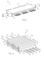
- FIG. 1 is an isometric view of an immersion cooling apparatus according to this invention, including set of three multi-terminal thermally conductive modules installed in a sealed housing.
- FIG. 2 is an exploded isometric view of the immersion cooling apparatus of FIG. 1 .
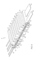
- FIG. 3 is an isometric view of the immersion cooling apparatus of FIG. 1 , with selected walls removed to reveal the thermally conductive modules and illustrate coolant flow through the housing.
- FIG. 4 is an isometric view of one of the thermally conductive modules of FIGS. 1-3 .
- FIG. 5 is an isometric cross-sectional view of the thermally conductive module of FIG. 4 .
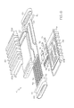
- FIG. 6 is an exploded isometric view of the thermally conductive module of FIG. 4 .
- FIGS. 1-3 depict an immersion cooling apparatus 10 according to the present invention.
- the apparatus 10 includes an elongate housing 12, and at least one thermally conductive module 14 partially enclosed in the housing 12.
- the apparatus 10 includes three identical thermally conductive modules 14, 15 and 16.
- FIGS. 4-6 depict a representative thermally conductive module M in detail.
- the housing 12 includes an elongate body portion 18 including oppositely disposed sidewalls 19 and 20, an inlet port 22, and an outlet port 24.
- the housing 12 has a hollow interior defining a flow-through chamber 26 joined to inlet port 22 at one end and outlet port 24 at the opposite end.
- a continuous flow of liquid coolant directed through inlet port 22 enters and fills the chamber 26, and excess coolant is exhausted from chamber 26 via outlet port 24 (as indicated by arrow 30 in FIG. 3 ).
- the tapered portion 26a of chamber 26 immediately downstream of inlet port 22 is open so that the in-coming coolant fans out to the entire width of the chamber 26 (as indicated by arrows 32 in FIG.
- the tapered portion 26b of chamber 26 immediately upstream of outlet port 24 is also open and collects the out-going coolant (as indicated by arrows 34 in FIG. 3 ) and directs it into the outlet port 24.
- the three thermally conductive modules 14-16 are disposed intermediate the tapered portions 26a and 26b.
- each includes a body portion 36 and a pair of oppositely disposed connector headers 38 and 40 extending outward from opposing ends of the body portion 36.
- the module M When the module M is installed in the housing 12 as illustrated in FIG. 3 , its body portion 36 is disposed entirely within the chamber 26, while the connector headers 38 and 40 extend outward through openings 19a, 20a formed in the housing sidewalls 19, 20.
- the sidewall 20 is initially removed as shown in FIG. 2 to install the modules 14-16 in the housing 12, and then slipped over the connector headers 40 and fastened to the body portion 18 of housing 12.
- a leak-proof seal around the sidewall openings 19a, 20a is achieved by a pair of O-rings 42, 44 disposed about the connector headers 38 and 40 against the module's body portion 36.
- the O-rings 42, 44 are compressed between the module's body portion 36 and the respective housing sidewalls 19, 20, forming the leak-proof seal.
- the modules 14-16 are supported within housing 12 by their respective connector headers 38, 40 so that their body portions 36 are effectively suspended in the housing chamber 26.
- the liquid coolant flowing through chamber 26 contacts all surfaces of the body portions 36.
- the surface area contacted by the coolant is maximized by providing a series of parallel ridges 46 in alignment with direction of coolant flow on the upper and lower faces of the body portions 36.
- the ridges 46 define a series of parallel channels through which the coolant can flow as illustrated by the sets of parallel arrows 48 in FIG. 3 , although coolant also flows between the ridges 46 and the periphery of the chamber 26.
- the thermally conductive module M is illustrated as an assembly of components, including the O-rings 42 and 44, a set of power-level and signal-level leadframe terminals 50 and 52, upper and lower body portion halves 62 and 64, a pair of retainer rings 66 and 68, and a substrate 70 supporting two bare-die IGBTs 72, two bare-die diodes 74 and several conductive spacers 76.
- the reference numeral 60 designates a plastic encapsulant that internally encapsulates the module components and partially over-molds the retainer rings 66 and 68, as also shown in FIG. 5 .
- the substrate 70 is mounted on the lower half 64 of body portion 36, the leadframe terminals 50 and 52 are soldered to the bare die 72, 74 and spacers 76, and the upper half 62 of body portion 36 is joined to the lower half 64.
- the connector header 38 is defined by the joined ends 62a, 64a of body portion halves 62, 64, and the retainer ring 66, which is slipped over the joined ends 62a, 64a.
- the connector header 40 is defined by the joined ends 62b, 64b of body portion halves 62, 64, and the retainer ring 68, which is slipped over the joined ends 62b, 64b.
- the internal construction of the module M is exemplary only, and it will be appreciated that the present invention is not limited thereto.
- the present invention provides an improved immersion cooling apparatus whereby one or more heat-dissipative power semiconductor devices are incorporated into a thermally conductive module that is installed in a housing having a chamber through which liquid coolant is circulated such that a body portion of the thermally conductive module is suspended in the chamber and immersed in the liquid coolant flowing there-through.
Landscapes
- Cooling Or The Like Of Semiconductors Or Solid State Devices (AREA)
- Cooling Or The Like Of Electrical Apparatus (AREA)
Abstract
Description
- The present invention relates to apparatus for cooling a power semiconductor device, and more particularly to an electronic module incorporating the power semiconductor device and a flow-through coolant chamber in which the electronic module is installed.
- Various arrangements have been devised for dissipating heat generated by power semiconductor devices such as IGBTs and MOSFETs. For example, a power device in the form of a semiconductor die can be mounted on an insulative but thermally conductive substrate (ceramic, for example) that, in turn, is thermally coupled (by solder or thermal grease) to an air-cooled or liquid-cooled heatsink. And in fact, a similar technique can be applied to both sides of a semiconductor die, as shown for example, in the
U.S. Patent No. 7,030,317 to Oman . It is also known that a power semiconductor device and substrate can be mounted in a chamber through which a liquid coolant flows; see, for example, theU.S. Patent No. 7,016,383 to Rice . - The present invention provides an improved immersion cooling apparatus for at least one semiconductor device, comprising a housing having an interior chamber, an inlet through which liquid coolant is supplied to said chamber, and an outlet through which liquid coolant is exhausted from said chamber. The apparatus further comprises a thermally conductive module incorporating the semiconductor device and installed in said housing, said thermally conductive module including a body portion and first and second connector headers extending outward from opposing ends of said body portion, where said first and second connector headers house terminals that are electrically coupled to said semiconductor device and respectively extend through first and second openings in oppositely disposed sidewalls of the housing such that said body portion is suspended in said chamber between said inlet and said outlet (24) and immersed in said liquid coolant. The immersion cooling apparatus further comprises raised ridges on the body portion of said thermally conductive module that are parallel to a flow of coolant through said chamber and, a first coolant seal compressed between said first connector header and said first opening; and a second coolant seal compressed between said second connector header and said second opening. One of said oppositely disposed sidewalls of said housing is removable to enable insertion of said thermally conductive module into said chamber. The immersion cooling apparatus as set in any of the preceding claim, further comprises one or more additional thermally conductive modules incorporating additional semiconductor devices and installed in said housing such that body portions of said one or more additional thermally conductive modules are suspended in said chamber between said inlet and said outlet and immersed in said liquid coolant.
-
FIG. 1 is an isometric view of an immersion cooling apparatus according to this invention, including set of three multi-terminal thermally conductive modules installed in a sealed housing. -
FIG. 2 is an exploded isometric view of the immersion cooling apparatus ofFIG. 1 . -
FIG. 3 is an isometric view of the immersion cooling apparatus ofFIG. 1 , with selected walls removed to reveal the thermally conductive modules and illustrate coolant flow through the housing. -
FIG. 4 is an isometric view of one of the thermally conductive modules ofFIGS. 1-3 . -
FIG. 5 is an isometric cross-sectional view of the thermally conductive module ofFIG. 4 . -
FIG. 6 is an exploded isometric view of the thermally conductive module ofFIG. 4 . - Referring to the drawings,
FIGS. 1-3 depict animmersion cooling apparatus 10 according to the present invention. In general, theapparatus 10 includes anelongate housing 12, and at least one thermallyconductive module 14 partially enclosed in thehousing 12. In the embodiment ofFIGS. 1-3 , theapparatus 10 includes three identical thermallyconductive modules FIGS. 4-6 depict a representative thermally conductive module M in detail. - Referring particularly to
FIGS. 1-3 , thehousing 12 includes anelongate body portion 18 including oppositely disposedsidewalls inlet port 22, and anoutlet port 24. Thehousing 12 has a hollow interior defining a flow-throughchamber 26 joined to inletport 22 at one end andoutlet port 24 at the opposite end. A continuous flow of liquid coolant directed through inlet port 22 (as indicated byarrow 28 inFIG. 3 ) enters and fills thechamber 26, and excess coolant is exhausted fromchamber 26 via outlet port 24 (as indicated byarrow 30 inFIG. 3 ). Thetapered portion 26a ofchamber 26 immediately downstream ofinlet port 22 is open so that the in-coming coolant fans out to the entire width of the chamber 26 (as indicated byarrows 32 inFIG. 3 ). Thetapered portion 26b ofchamber 26 immediately upstream ofoutlet port 24 is also open and collects the out-going coolant (as indicated byarrows 34 inFIG. 3 ) and directs it into theoutlet port 24. And as best illustrated inFIG. 3 , the three thermally conductive modules 14-16 are disposed intermediate thetapered portions - Referring to the representative thermally conductive module M of
FIGS. 4-5 , each includes abody portion 36 and a pair of oppositely disposedconnector headers body portion 36. When the module M is installed in thehousing 12 as illustrated inFIG. 3 , itsbody portion 36 is disposed entirely within thechamber 26, while theconnector headers openings housing sidewalls sidewall 20 is initially removed as shown inFIG. 2 to install the modules 14-16 in thehousing 12, and then slipped over theconnector headers 40 and fastened to thebody portion 18 ofhousing 12. A leak-proof seal around thesidewall openings rings connector headers body portion 36. When theremovable sidewall 20 is fastened to thebody portion 18 ofhousing 12, the O-rings body portion 36 and therespective housing sidewalls - Significantly, the modules 14-16 are supported within
housing 12 by theirrespective connector headers body portions 36 are effectively suspended in thehousing chamber 26. As a result, the liquid coolant flowing throughchamber 26 contacts all surfaces of thebody portions 36. And in the illustrated embodiment, the surface area contacted by the coolant is maximized by providing a series ofparallel ridges 46 in alignment with direction of coolant flow on the upper and lower faces of thebody portions 36. In effect, theridges 46 define a series of parallel channels through which the coolant can flow as illustrated by the sets ofparallel arrows 48 inFIG. 3 , although coolant also flows between theridges 46 and the periphery of thechamber 26. - Referring to
FIG. 6 , the thermally conductive module M is illustrated as an assembly of components, including the O-rings level leadframe terminals body portion halves retainer rings substrate 70 supporting two bare-die IGBTs 72, two bare-die diodes 74 and severalconductive spacers 76. Thereference numeral 60 designates a plastic encapsulant that internally encapsulates the module components and partially over-molds theretainer rings FIG. 5 . Thesubstrate 70 is mounted on thelower half 64 ofbody portion 36, theleadframe terminals bare die spacers 76, and theupper half 62 ofbody portion 36 is joined to thelower half 64. Theconnector header 38 is defined by the joinedends body portion halves retainer ring 66, which is slipped over the joinedends connector header 40 is defined by the joinedends body portion halves retainer ring 68, which is slipped over the joinedends - In summary, the present invention provides an improved immersion cooling apparatus whereby one or more heat-dissipative power semiconductor devices are incorporated into a thermally conductive module that is installed in a housing having a chamber through which liquid coolant is circulated such that a body portion of the thermally conductive module is suspended in the chamber and immersed in the liquid coolant flowing there-through.
Claims (5)
- Immersion cooling apparatus for at least one semiconductor device (72, 74), comprising:a housing (12) having an interior chamber (26), an inlet (22) through which liquid coolant is supplied to said chamber (26), and an outlet (24) through which liquid coolant is exhausted from said chamber (26); characterized in that the apparatus further comprisesa thermally conductive module (14) incorporating the semiconductor device (72, 74) and installed in said housing (12), said thermally conductive module (14) including a body portion (36) and first and second connector headers (38, 40) extending outward from opposing ends of said body portion (36), where said first and second connector headers (38, 40) house terminals (50, 52) that are electrically coupled to said semiconductor device (72, 74) and respectively extend through first and second openings (19a, ,20a) in oppositely disposed sidewalls (19, 20) of the housing (12) such that said body portion (36) is suspended in said chamber (26) between said inlet (22) and said outlet (24) and immersed in said liquid coolant.
- The immersion cooling apparatus of claim 1, further comprising:raised ridges (46) on the body portion (36) of said thermally conductive module (14) that are parallel to a flow of coolant through said chamber (26).
- The immersion cooling apparatus as set in any of the preceding claim, further comprising:a first coolant seal (42) compressed between said first connector header (38) and said first opening (19a); anda second coolant seal (44) compressed between said second connector header (40) and said second opening (20a).
- The immersion cooling apparatus as set in any of the preceding claim, where:one of said oppositely disposed sidewalls (20) of said housing (12) is removable to enable insertion of said thermally conductive module (14) into said chamber (26).
- The immersion cooling apparatus as set in any of the preceding claim, further comprising:one or more additional thermally conductive modules (15, 16) incorporating additional semiconductor devices (72, 74) and installed in said housing (12) such that body portions (36) of said one or more additional thermally conductive modules (15, 16) are suspended in said chamber (26) between said inlet (22) and said outlet (24) and immersed in said liquid coolant.
Applications Claiming Priority (1)
| Application Number | Priority Date | Filing Date | Title |
|---|---|---|---|
| US12/624,093 US8094454B2 (en) | 2009-11-23 | 2009-11-23 | Immersion cooling apparatus for a power semiconductor device |
Publications (2)
| Publication Number | Publication Date |
|---|---|
| EP2325880A2 true EP2325880A2 (en) | 2011-05-25 |
| EP2325880A3 EP2325880A3 (en) | 2018-01-03 |
Family
ID=43629510
Family Applications (1)
| Application Number | Title | Priority Date | Filing Date |
|---|---|---|---|
| EP10191187.3A Withdrawn EP2325880A3 (en) | 2009-11-23 | 2010-11-15 | Immersion cooling apparatus for a power semiconductor device |
Country Status (2)
| Country | Link |
|---|---|
| US (1) | US8094454B2 (en) |
| EP (1) | EP2325880A3 (en) |
Cited By (5)
| Publication number | Priority date | Publication date | Assignee | Title |
|---|---|---|---|---|
| EP2814310A3 (en) * | 2013-06-14 | 2015-04-08 | Delphi Technologies, Inc. | Edge seal for electronics assembly suitable for exposure to electrically conductive coolant |
| US9131630B2 (en) | 2012-03-28 | 2015-09-08 | Delphi Technologies, Inc. | Edge seal for electronics assembly suitable for exposure to electrically conductive coolant |
| US20160260654A1 (en) | 2015-03-03 | 2016-09-08 | Infineon Technologies Ag | Plastic cooler for semiconductor modules |
| US9449895B2 (en) | 2013-05-03 | 2016-09-20 | Infineon Technologies Ag | Cooling system for molded modules and corresponding manufacturing methods |
| EP4301101A4 (en) * | 2021-04-28 | 2024-08-14 | BYD Company Limited | ENGINE CONTROL DEVICE AND VEHICLE COMPRISING SAME |
Families Citing this family (26)
| Publication number | Priority date | Publication date | Assignee | Title |
|---|---|---|---|---|
| TWI423403B (en) * | 2007-09-17 | 2014-01-11 | 萬國商業機器公司 | Integrated circuit stack |
| WO2012070129A1 (en) * | 2010-11-24 | 2012-05-31 | トヨタ自動車株式会社 | Stacked cooler |
| US20130044431A1 (en) * | 2011-08-18 | 2013-02-21 | Harris Corporation | Liquid cooling of stacked die through substrate lamination |
| US8711565B2 (en) * | 2011-11-02 | 2014-04-29 | General Electric Company | System and method for operating an electric power converter |
| DE112012005472T5 (en) * | 2011-12-26 | 2014-09-11 | Mitsubishi Electric Corporation | Electric power semiconductor device and method of manufacturing the same |
| US9142482B2 (en) * | 2011-12-27 | 2015-09-22 | Intel Corporation | Transient thermal management systems for semiconductor devices |
| US9255741B2 (en) | 2012-01-26 | 2016-02-09 | Lear Corporation | Cooled electric assembly |
| US8699225B2 (en) * | 2012-03-28 | 2014-04-15 | Delphi Technologies, Inc. | Liquid cooled electronics assembly suitable to use electrically conductive coolant |
| US20130306273A1 (en) * | 2012-05-18 | 2013-11-21 | International Business Machines Corporation | Apparatus for the compact cooling of an array of components |
| JP5851372B2 (en) | 2012-09-28 | 2016-02-03 | 日立オートモティブシステムズ株式会社 | Power converter |
| TWI494051B (en) * | 2012-11-19 | 2015-07-21 | 宏碁股份有限公司 | Fluid heat exchange device |
| KR101278633B1 (en) * | 2013-02-25 | 2013-06-25 | 김종선 | Heat dissipation system for a server |
| DE112014004189T5 (en) * | 2013-09-12 | 2016-06-02 | Hanon Systems | Heat exchanger for cooling an electrical component |
| US9332674B2 (en) | 2013-10-21 | 2016-05-03 | International Business Machines Corporation | Field-replaceable bank of immersion-cooled electronic components |
| US9282678B2 (en) | 2013-10-21 | 2016-03-08 | International Business Machines Corporation | Field-replaceable bank of immersion-cooled electronic components and separable heat sinks |
| CA2978795A1 (en) | 2015-03-16 | 2016-09-22 | Dana Canada Corporation | Heat exchangers with plates having surface patterns for enhancing flatness and methods for manufacturing same |
| DE102015213164A1 (en) * | 2015-07-14 | 2017-01-19 | Conti Temic Microelectronic Gmbh | Power electronics assembly, inverter with a power electronics assembly |
| US10146275B2 (en) * | 2016-02-17 | 2018-12-04 | Microsoft Technology Licensing, Llc | 3D printed thermal management system |
| US10020242B2 (en) | 2016-04-14 | 2018-07-10 | Hamilton Sundstrand Corporation | Immersion cooling arrangements for electronic devices |
| US9955613B2 (en) * | 2016-09-13 | 2018-04-24 | Denso International America, Inc. | Cooler and power electronic module having the same |
| US10523094B2 (en) * | 2017-03-15 | 2019-12-31 | Karma Automotive Llc | Power inverter with liquid cooled busbars |
| US20220130735A1 (en) * | 2020-10-23 | 2022-04-28 | GM Global Technology Operations LLC | Package for power semiconductor device and method of manufacturing the same |
| US12205918B2 (en) | 2021-06-16 | 2025-01-21 | Semiconductor Components Industries, Llc | Submodule semiconductor package |
| US12266590B2 (en) | 2021-07-14 | 2025-04-01 | Semiconductor Components Industries, Llc | Dual side direct cooling semiconductor package |
| US12174676B2 (en) | 2021-11-22 | 2024-12-24 | Google Llc | Modular liquid cooling architecture for liquid cooling |
| US20230247795A1 (en) | 2022-01-28 | 2023-08-03 | The Research Foundation For The State University Of New York | Regenerative preheater for phase change cooling applications |
Citations (2)
| Publication number | Priority date | Publication date | Assignee | Title |
|---|---|---|---|---|
| US7016383B2 (en) | 2003-08-27 | 2006-03-21 | Northrop Grumman Corporation | Immersion-cooled monolithic laser diode array and method of manufacturing the same |
| US7030317B1 (en) | 2005-04-13 | 2006-04-18 | Delphi Technologies, Inc. | Electronic assembly with stacked integrated circuit die |
Family Cites Families (35)
| Publication number | Priority date | Publication date | Assignee | Title |
|---|---|---|---|---|
| US3616533A (en) * | 1969-10-28 | 1971-11-02 | North American Rockwell | Method of protecting articles in high temperature environment |
| KR900001393B1 (en) * | 1985-04-30 | 1990-03-09 | Fujitsu Ltd | Evaporation cooling module for semiconductor device |
| US5014161A (en) * | 1985-07-22 | 1991-05-07 | Digital Equipment Corporation | System for detachably mounting semiconductors on conductor substrate |
| US4765397A (en) * | 1986-11-28 | 1988-08-23 | International Business Machines Corp. | Immersion cooled circuit module with improved fins |
| US4995892A (en) * | 1989-12-19 | 1991-02-26 | Ppg Industries, Inc. | Process and apparatus for controlling the thermal environment of glass fiber forming |
| US5006924A (en) * | 1989-12-29 | 1991-04-09 | International Business Machines Corporation | Heat sink for utilization with high density integrated circuit substrates |
| JPH03229493A (en) * | 1990-02-05 | 1991-10-11 | Fujitsu Ltd | Immersion cooling structure |
| US5168919A (en) * | 1990-06-29 | 1992-12-08 | Digital Equipment Corporation | Air cooled heat exchanger for multi-chip assemblies |
| US5305184A (en) * | 1992-12-16 | 1994-04-19 | Ibm Corporation | Method and apparatus for immersion cooling or an electronic board |
| US5485671A (en) * | 1993-09-10 | 1996-01-23 | Aavid Laboratories, Inc. | Method of making a two-phase thermal bag component cooler |
| US5448108A (en) * | 1993-11-02 | 1995-09-05 | Hughes Aircraft Company | Cooling of semiconductor power modules by flushing with dielectric liquid |
| US5774334A (en) * | 1994-08-26 | 1998-06-30 | Hitachi, Ltd. | Low thermal resistant, fluid-cooled semiconductor module |
| US5495490A (en) * | 1995-02-28 | 1996-02-27 | Mcdonnell Douglas Corporation | Immersion method and apparatus for cooling a semiconductor laser device |
| MY115676A (en) * | 1996-08-06 | 2003-08-30 | Advantest Corp | Printed circuit board with electronic devices mounted thereon |
| DE19643717A1 (en) * | 1996-10-23 | 1998-04-30 | Asea Brown Boveri | Liquid cooling device for a high-performance semiconductor module |
| JP3518434B2 (en) * | 1999-08-11 | 2004-04-12 | 株式会社日立製作所 | Multi-chip module cooling system |
| EP1148547B8 (en) * | 2000-04-19 | 2016-01-06 | Denso Corporation | Coolant cooled type semiconductor device |
| US20020162673A1 (en) * | 2001-05-03 | 2002-11-07 | Cook Derrick E. | Use of doped synthetic polymer materials for packaging of power electric assemblies for a liquid cooled module |
| JP3946018B2 (en) * | 2001-09-18 | 2007-07-18 | 株式会社日立製作所 | Liquid-cooled circuit device |
| US6744136B2 (en) * | 2001-10-29 | 2004-06-01 | International Rectifier Corporation | Sealed liquid cooled electronic device |
| US7064953B2 (en) * | 2001-12-27 | 2006-06-20 | Formfactor, Inc. | Electronic package with direct cooling of active electronic components |
| US6724792B2 (en) * | 2002-09-12 | 2004-04-20 | The Boeing Company | Laser diode arrays with replaceable laser diode bars and methods of removing and replacing laser diode bars |
| US7133286B2 (en) * | 2004-05-10 | 2006-11-07 | International Business Machines Corporation | Method and apparatus for sealing a liquid cooled electronic device |
| US7205653B2 (en) * | 2004-08-17 | 2007-04-17 | Delphi Technologies, Inc. | Fluid cooled encapsulated microelectronic package |
| US8125781B2 (en) * | 2004-11-11 | 2012-02-28 | Denso Corporation | Semiconductor device |
| JP4379339B2 (en) * | 2005-01-19 | 2009-12-09 | トヨタ自動車株式会社 | Semiconductor cooling device |
| US7077189B1 (en) * | 2005-01-21 | 2006-07-18 | Delphi Technologies, Inc. | Liquid cooled thermosiphon with flexible coolant tubes |
| US7365981B2 (en) * | 2005-06-28 | 2008-04-29 | Delphi Technologies, Inc. | Fluid-cooled electronic system |
| US7411290B2 (en) * | 2005-08-05 | 2008-08-12 | Delphi Technologies, Inc. | Integrated circuit chip and method for cooling an integrated circuit chip |
| US7551439B2 (en) * | 2006-03-28 | 2009-06-23 | Delphi Technologies, Inc. | Fluid cooled electronic assembly |
| US7608924B2 (en) * | 2007-05-03 | 2009-10-27 | Delphi Technologies, Inc. | Liquid cooled power electronic circuit comprising stacked direct die cooled packages |
| JP4580997B2 (en) * | 2008-03-11 | 2010-11-17 | 日立オートモティブシステムズ株式会社 | Power converter |
| US7660335B2 (en) * | 2008-04-17 | 2010-02-09 | Lasertel, Inc. | Liquid cooled laser bar arrays incorporating diamond/copper expansion matched materials |
| JP4797077B2 (en) * | 2009-02-18 | 2011-10-19 | 株式会社日立製作所 | Semiconductor power module, power converter, and method for manufacturing semiconductor power module |
| US8014150B2 (en) * | 2009-06-25 | 2011-09-06 | International Business Machines Corporation | Cooled electronic module with pump-enhanced, dielectric fluid immersion-cooling |
-
2009
- 2009-11-23 US US12/624,093 patent/US8094454B2/en active Active
-
2010
- 2010-11-15 EP EP10191187.3A patent/EP2325880A3/en not_active Withdrawn
Patent Citations (2)
| Publication number | Priority date | Publication date | Assignee | Title |
|---|---|---|---|---|
| US7016383B2 (en) | 2003-08-27 | 2006-03-21 | Northrop Grumman Corporation | Immersion-cooled monolithic laser diode array and method of manufacturing the same |
| US7030317B1 (en) | 2005-04-13 | 2006-04-18 | Delphi Technologies, Inc. | Electronic assembly with stacked integrated circuit die |
Cited By (8)
| Publication number | Priority date | Publication date | Assignee | Title |
|---|---|---|---|---|
| US9131630B2 (en) | 2012-03-28 | 2015-09-08 | Delphi Technologies, Inc. | Edge seal for electronics assembly suitable for exposure to electrically conductive coolant |
| US9449895B2 (en) | 2013-05-03 | 2016-09-20 | Infineon Technologies Ag | Cooling system for molded modules and corresponding manufacturing methods |
| EP2814310A3 (en) * | 2013-06-14 | 2015-04-08 | Delphi Technologies, Inc. | Edge seal for electronics assembly suitable for exposure to electrically conductive coolant |
| US20160260654A1 (en) | 2015-03-03 | 2016-09-08 | Infineon Technologies Ag | Plastic cooler for semiconductor modules |
| US9613885B2 (en) | 2015-03-03 | 2017-04-04 | Infineon Technologies Ag | Plastic cooler for semiconductor modules |
| US9934990B2 (en) | 2015-03-03 | 2018-04-03 | Infineon Technologies Ag | Method of manufacturing a cooler for semiconductor modules |
| US10199238B2 (en) | 2015-03-03 | 2019-02-05 | Infineon Technologies Ag | Semiconductor module cooling system |
| EP4301101A4 (en) * | 2021-04-28 | 2024-08-14 | BYD Company Limited | ENGINE CONTROL DEVICE AND VEHICLE COMPRISING SAME |
Also Published As
| Publication number | Publication date |
|---|---|
| US20110122583A1 (en) | 2011-05-26 |
| EP2325880A3 (en) | 2018-01-03 |
| US8094454B2 (en) | 2012-01-10 |
Similar Documents
| Publication | Publication Date | Title |
|---|---|---|
| US8094454B2 (en) | Immersion cooling apparatus for a power semiconductor device | |
| CN107484387B (en) | Immersed liquid cooling device, blade server and rack server | |
| EP2840604B1 (en) | Semiconductor device and cooler for semiconductor device | |
| US9460985B2 (en) | Cooling apparatuses having a jet orifice surface with alternating vapor guide channels | |
| JP5700034B2 (en) | Semiconductor module and cooler | |
| US10224265B2 (en) | Power electronics assemblies having a semiconductor cooling chip and an integrated fluid channel system | |
| CN104134639B (en) | Cooling system and corresponding manufacture method for molding modules | |
| US9099295B2 (en) | Cooling apparatuses having sloped vapor outlet channels | |
| US11647607B2 (en) | Localized immersion cooling enclosure with thermal efficiency features | |
| KR101606456B1 (en) | Battery Module | |
| US20220174840A1 (en) | Cooling arrangement | |
| US20200279789A1 (en) | Heat sink for a power semiconductor module | |
| CN207219278U (en) | A kind of electrical equipment and its radiator structure | |
| CN210840488U (en) | Heat radiator | |
| US11026343B1 (en) | Thermodynamic heat exchanger | |
| US20260075753A1 (en) | Fluid-cooled thermal support structure for electronics device having array of projections with non-uniform arrangement | |
| CN221727101U (en) | High-power direct oil-cooled power module | |
| CN112020269B (en) | Device for conducting heat and electronic equipment | |
| JP2025511209A (en) | High thermal capacity heat sink | |
| JP2025513112A (en) | Semiconductor power device, semiconductor power system, and cooling method for semiconductor power device |
Legal Events
| Date | Code | Title | Description |
|---|---|---|---|
| PUAI | Public reference made under article 153(3) epc to a published international application that has entered the european phase |
Free format text: ORIGINAL CODE: 0009012 |
|
| AK | Designated contracting states |
Kind code of ref document: A2 Designated state(s): AL AT BE BG CH CY CZ DE DK EE ES FI FR GB GR HR HU IE IS IT LI LT LU LV MC MK MT NL NO PL PT RO RS SE SI SK SM TR |
|
| AX | Request for extension of the european patent |
Extension state: BA ME |
|
| PUAL | Search report despatched |
Free format text: ORIGINAL CODE: 0009013 |
|
| AK | Designated contracting states |
Kind code of ref document: A3 Designated state(s): AL AT BE BG CH CY CZ DE DK EE ES FI FR GB GR HR HU IE IS IT LI LT LU LV MC MK MT NL NO PL PT RO RS SE SI SK SM TR |
|
| AX | Request for extension of the european patent |
Extension state: BA ME |
|
| RIC1 | Information provided on ipc code assigned before grant |
Ipc: H01L 23/40 20060101ALN20171128BHEP Ipc: H01L 23/473 20060101ALI20171128BHEP Ipc: H01L 23/44 20060101ALI20171128BHEP Ipc: H01L 23/433 20060101AFI20171128BHEP |
|
| STAA | Information on the status of an ep patent application or granted ep patent |
Free format text: STATUS: THE APPLICATION IS DEEMED TO BE WITHDRAWN |
|
| 18D | Application deemed to be withdrawn |
Effective date: 20180704 |