EP2325458A2 - Bellows preload and centering spring for a fan drive gear system - Google Patents
Bellows preload and centering spring for a fan drive gear system Download PDFInfo
- Publication number
- EP2325458A2 EP2325458A2 EP20100251977 EP10251977A EP2325458A2 EP 2325458 A2 EP2325458 A2 EP 2325458A2 EP 20100251977 EP20100251977 EP 20100251977 EP 10251977 A EP10251977 A EP 10251977A EP 2325458 A2 EP2325458 A2 EP 2325458A2
- Authority
- EP
- European Patent Office
- Prior art keywords
- tapered roller
- roller bearing
- bearing
- bellows spring
- assembly
- Prior art date
- Legal status (The legal status is an assumption and is not a legal conclusion. Google has not performed a legal analysis and makes no representation as to the accuracy of the status listed.)
- Granted
Links
- 230000036316 preload Effects 0.000 title claims abstract description 19
- 238000000034 method Methods 0.000 claims abstract description 8
- 125000006850 spacer group Chemical group 0.000 claims description 4
- 229910000831 Steel Inorganic materials 0.000 claims 1
- 239000010959 steel Substances 0.000 claims 1
- 238000004519 manufacturing process Methods 0.000 description 5
- OKTJSMMVPCPJKN-UHFFFAOYSA-N Carbon Chemical compound [C] OKTJSMMVPCPJKN-UHFFFAOYSA-N 0.000 description 1
- 238000003491 array Methods 0.000 description 1
- 229910052799 carbon Inorganic materials 0.000 description 1
- 239000000463 material Substances 0.000 description 1
- 238000012986 modification Methods 0.000 description 1
- 230000004048 modification Effects 0.000 description 1
- 238000010248 power generation Methods 0.000 description 1
- 230000000717 retained effect Effects 0.000 description 1
- 238000007789 sealing Methods 0.000 description 1
- 229910001220 stainless steel Inorganic materials 0.000 description 1
- 239000010935 stainless steel Substances 0.000 description 1
Images

Classifications
-
- F—MECHANICAL ENGINEERING; LIGHTING; HEATING; WEAPONS; BLASTING
- F01—MACHINES OR ENGINES IN GENERAL; ENGINE PLANTS IN GENERAL; STEAM ENGINES
- F01D—NON-POSITIVE DISPLACEMENT MACHINES OR ENGINES, e.g. STEAM TURBINES
- F01D25/00—Component parts, details, or accessories, not provided for in, or of interest apart from, other groups
- F01D25/16—Arrangement of bearings; Supporting or mounting bearings in casings
- F01D25/162—Bearing supports
- F01D25/164—Flexible supports; Vibration damping means associated with the bearing
-
- F—MECHANICAL ENGINEERING; LIGHTING; HEATING; WEAPONS; BLASTING
- F02—COMBUSTION ENGINES; HOT-GAS OR COMBUSTION-PRODUCT ENGINE PLANTS
- F02C—GAS-TURBINE PLANTS; AIR INTAKES FOR JET-PROPULSION PLANTS; CONTROLLING FUEL SUPPLY IN AIR-BREATHING JET-PROPULSION PLANTS
- F02C3/00—Gas-turbine plants characterised by the use of combustion products as the working fluid
- F02C3/04—Gas-turbine plants characterised by the use of combustion products as the working fluid having a turbine driving a compressor
- F02C3/107—Gas-turbine plants characterised by the use of combustion products as the working fluid having a turbine driving a compressor with two or more rotors connected by power transmission
-
- F—MECHANICAL ENGINEERING; LIGHTING; HEATING; WEAPONS; BLASTING
- F02—COMBUSTION ENGINES; HOT-GAS OR COMBUSTION-PRODUCT ENGINE PLANTS
- F02C—GAS-TURBINE PLANTS; AIR INTAKES FOR JET-PROPULSION PLANTS; CONTROLLING FUEL SUPPLY IN AIR-BREATHING JET-PROPULSION PLANTS
- F02C7/00—Features, components parts, details or accessories, not provided for in, or of interest apart form groups F02C1/00 - F02C6/00; Air intakes for jet-propulsion plants
- F02C7/06—Arrangements of bearings; Lubricating
-
- F—MECHANICAL ENGINEERING; LIGHTING; HEATING; WEAPONS; BLASTING
- F02—COMBUSTION ENGINES; HOT-GAS OR COMBUSTION-PRODUCT ENGINE PLANTS
- F02K—JET-PROPULSION PLANTS
- F02K3/00—Plants including a gas turbine driving a compressor or a ducted fan
- F02K3/02—Plants including a gas turbine driving a compressor or a ducted fan in which part of the working fluid by-passes the turbine and combustion chamber
- F02K3/04—Plants including a gas turbine driving a compressor or a ducted fan in which part of the working fluid by-passes the turbine and combustion chamber the plant including ducted fans, i.e. fans with high volume, low pressure outputs, for augmenting the jet thrust, e.g. of double-flow type
- F02K3/06—Plants including a gas turbine driving a compressor or a ducted fan in which part of the working fluid by-passes the turbine and combustion chamber the plant including ducted fans, i.e. fans with high volume, low pressure outputs, for augmenting the jet thrust, e.g. of double-flow type with front fan
-
- F—MECHANICAL ENGINEERING; LIGHTING; HEATING; WEAPONS; BLASTING
- F16—ENGINEERING ELEMENTS AND UNITS; GENERAL MEASURES FOR PRODUCING AND MAINTAINING EFFECTIVE FUNCTIONING OF MACHINES OR INSTALLATIONS; THERMAL INSULATION IN GENERAL
- F16C—SHAFTS; FLEXIBLE SHAFTS; ELEMENTS OR CRANKSHAFT MECHANISMS; ROTARY BODIES OTHER THAN GEARING ELEMENTS; BEARINGS
- F16C19/00—Bearings with rolling contact, for exclusively rotary movement
- F16C19/54—Systems consisting of a plurality of bearings with rolling friction
- F16C19/546—Systems with spaced apart rolling bearings including at least one angular contact bearing
- F16C19/547—Systems with spaced apart rolling bearings including at least one angular contact bearing with two angular contact rolling bearings
- F16C19/548—Systems with spaced apart rolling bearings including at least one angular contact bearing with two angular contact rolling bearings in O-arrangement
-
- F—MECHANICAL ENGINEERING; LIGHTING; HEATING; WEAPONS; BLASTING
- F16—ENGINEERING ELEMENTS AND UNITS; GENERAL MEASURES FOR PRODUCING AND MAINTAINING EFFECTIVE FUNCTIONING OF MACHINES OR INSTALLATIONS; THERMAL INSULATION IN GENERAL
- F16C—SHAFTS; FLEXIBLE SHAFTS; ELEMENTS OR CRANKSHAFT MECHANISMS; ROTARY BODIES OTHER THAN GEARING ELEMENTS; BEARINGS
- F16C25/00—Bearings for exclusively rotary movement adjustable for wear or play
- F16C25/06—Ball or roller bearings
- F16C25/08—Ball or roller bearings self-adjusting
- F16C25/083—Ball or roller bearings self-adjusting with resilient means acting axially on a race ring to preload the bearing
-
- F—MECHANICAL ENGINEERING; LIGHTING; HEATING; WEAPONS; BLASTING
- F05—INDEXING SCHEMES RELATING TO ENGINES OR PUMPS IN VARIOUS SUBCLASSES OF CLASSES F01-F04
- F05D—INDEXING SCHEME FOR ASPECTS RELATING TO NON-POSITIVE-DISPLACEMENT MACHINES OR ENGINES, GAS-TURBINES OR JET-PROPULSION PLANTS
- F05D2260/00—Function
- F05D2260/30—Retaining components in desired mutual position
- F05D2260/38—Retaining components in desired mutual position by a spring, i.e. spring loaded or biased towards a certain position
-
- F—MECHANICAL ENGINEERING; LIGHTING; HEATING; WEAPONS; BLASTING
- F16—ENGINEERING ELEMENTS AND UNITS; GENERAL MEASURES FOR PRODUCING AND MAINTAINING EFFECTIVE FUNCTIONING OF MACHINES OR INSTALLATIONS; THERMAL INSULATION IN GENERAL
- F16C—SHAFTS; FLEXIBLE SHAFTS; ELEMENTS OR CRANKSHAFT MECHANISMS; ROTARY BODIES OTHER THAN GEARING ELEMENTS; BEARINGS
- F16C19/00—Bearings with rolling contact, for exclusively rotary movement
- F16C19/22—Bearings with rolling contact, for exclusively rotary movement with bearing rollers essentially of the same size in one or more circular rows, e.g. needle bearings
- F16C19/34—Bearings with rolling contact, for exclusively rotary movement with bearing rollers essentially of the same size in one or more circular rows, e.g. needle bearings for both radial and axial load
- F16C19/36—Bearings with rolling contact, for exclusively rotary movement with bearing rollers essentially of the same size in one or more circular rows, e.g. needle bearings for both radial and axial load with a single row of rollers
- F16C19/364—Bearings with rolling contact, for exclusively rotary movement with bearing rollers essentially of the same size in one or more circular rows, e.g. needle bearings for both radial and axial load with a single row of rollers with tapered rollers, i.e. rollers having essentially the shape of a truncated cone
-
- F—MECHANICAL ENGINEERING; LIGHTING; HEATING; WEAPONS; BLASTING
- F16—ENGINEERING ELEMENTS AND UNITS; GENERAL MEASURES FOR PRODUCING AND MAINTAINING EFFECTIVE FUNCTIONING OF MACHINES OR INSTALLATIONS; THERMAL INSULATION IN GENERAL
- F16C—SHAFTS; FLEXIBLE SHAFTS; ELEMENTS OR CRANKSHAFT MECHANISMS; ROTARY BODIES OTHER THAN GEARING ELEMENTS; BEARINGS
- F16C2360/00—Engines or pumps
- F16C2360/23—Gas turbine engines
-
- Y—GENERAL TAGGING OF NEW TECHNOLOGICAL DEVELOPMENTS; GENERAL TAGGING OF CROSS-SECTIONAL TECHNOLOGIES SPANNING OVER SEVERAL SECTIONS OF THE IPC; TECHNICAL SUBJECTS COVERED BY FORMER USPC CROSS-REFERENCE ART COLLECTIONS [XRACs] AND DIGESTS
- Y10—TECHNICAL SUBJECTS COVERED BY FORMER USPC
- Y10T—TECHNICAL SUBJECTS COVERED BY FORMER US CLASSIFICATION
- Y10T29/00—Metal working
- Y10T29/49—Method of mechanical manufacture
- Y10T29/49636—Process for making bearing or component thereof
- Y10T29/49643—Rotary bearing
- Y10T29/49679—Anti-friction bearing or component thereof
Definitions
- the present invention relates to gas turbine engines, and more particularly, to engines with a fan drive gear system having tapered roller bearings.
- anti-friction bearings including tapered roller bearings.
- anti-friction bearings are enclosed in bearing compartments with small envelopes that circumscribe the engine shaft.
- a fan shaft connects a forward-most spool of the engine to a fan.
- the fan shaft is relatively short making it susceptible to instability.
- an assembly of tapered roller bearings is used to support the fan shaft in two locations along its length to provide for greater shaft stability (i.e. to increase the wheelbase length of the fan shaft).
- a spring load must be maintained between the tapered roller bearings to keep the rollers in contact with the raceways.
- An assembly includes a first tapered roller bearing and a second tapered roller bearing and a bellows spring.
- the bellows spring is disposed adjacent the first tapered roller bearing and the second tapered roller bearing.
- a method for applying a preload to a first tapered roller bearing and a second tapered roller bearing includes a bellows spring that is disposed between the first tapered roller bearing and the second tapered roller bearing to apply the preload to both the first tapered roller bearing and the second tapered roller bearing.
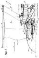
- FIG. 1 is a schematic cross-section of a forward portion of a gas turbine engine.
- FIG. 2 is a perspective cross-sectional view of a bearing compartment including a first tapered roller bearing, a second tapered roller bearing and a bellows spring.
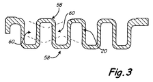
- FIG. 3 is an enlarged cross section of the bellows spring of FIG. 2 .
- the present application describes a method and an assembly for applying preload to a first tapered roller bearing and a second tapered roller bearing in a bearing compartment of a gas turbine engine.
- a bellows spring allows a single element to be used in the confined space of a bearing compartment, thereby saving space and reducing manufacturing costs.
- the bellows spring is adapted to apply preload to first and second tapered roller bearings in an axial direction (along the engine centerline), and acts as a centering spring (i.e. has a radial stiffness with respect to the engine centerline) for a squeeze film damper system.
- the bellows spring is accommodating of flexing in the radial direction by the first tapered roller bearing and the second tapered roller bearing such that the bellows spring does not wear on the surfaces of bearings.
- FIG. 1 shows a forward section of gas turbine engine 10 above engine centerline C L of gas turbine engine 10.
- Gas turbine engine 10 includes bearing compartment 12, first and second tapered roller bearings 14A and 14B, fan shaft 16, bearing support 18, bellows spring 20, fan hub 22, nut 23, fan blades 24, fan nose 26, engine shaft 28, fan drive gear system 30, compressor section 32, guide vanes 34, and engine case 36.
- Bearing compartment 12 is disposed adjacent fan shaft 16 and contains first and second tapered roller bearings 14A and 14B therein.
- Fan shaft 16 rotates about an axis that aligns with engine centerline axis C L and is supported on tapered roller bearings 14A and 14B.
- Bearing compartment 12 is bounded by fan shaft 16 and bearing support 18 which connects to the tapered roller bearings 14A and 14B.
- Bearing support 18 extends to connect to a non-rotational frame such as an engine case of gas turbine engine 10.
- Bellows spring 20 is disposed in bearing compartment 12 adjacent first tapered roller bearing 14A and second tapered roller bearing 14B. Bellows spring 20 applies a preload to both first tapered roller bearing 14A and second tapered roller bearing 14B.
- Nut 23 is positioned adjacent the fan hub 22 and applies a clamping force to the radially inner race portion of first tapered roller bearing 14A and the inner race portion of second tapered roller bearing 14B
- Fan shaft 16 connects to and turns fan blades 24 through fan hub 22.
- Fan hub 22 also connects to fan nose 26.
- Fan shaft 16 connects to engine shaft 28 via fan drive gear system 30.
- Compressor section 32 is disposed radially outward of engine centerline C L and is connected to engine shaft 28.
- Guide vanes 34 are disposed radially outward of compressor section 32 and are rotatable relative to engine case 36.
- gas turbine engine 10 comprises a high bypass ratio geared turbofan engine.
- gas turbine engine 10 can comprise another type of gas turbine engine used for aircraft propulsion or power generation.
- bearing compartment 12 can comprise any bearing compartment in engine 10.
- Fan shaft 16 and compressor section 32 are connected to a turbine section (not shown) through engine shaft 28.
- Inlet air A enters engine 10 whereby it is divided into streams of a primary air Ap and a secondary air As after passing through the fan blades 18.
- the fan blades 24 are rotated by turbine section (not shown) of engine 10 through engine shaft 28 to accelerate the secondary air As (also known as bypass air) through exit guide vanes 34, thereby producing a significant portion of the thrust output of engine 10.
- the primary air Ap also known as gas path air
- Compressor section 32 works together to incrementally increase the pressure and temperature of primary air Ap.
- FIG. 2 shows a perspective cross-sectional view of bearing compartment 12 including first tapered roller bearing 14A, second tapered roller bearing 14B, and bellows spring 20. Additionally, bearing compartment 12 includes seal plate 38, bearing spacer 40, gear 42, secondary sleeve 44, and squeeze film damper system 46. First and second tapered roller bearings 14A and 14B include inner races 48A and 48B, roller elements 50A and 50B, and outer races 52A and 52B, respectively. Also shown are shoulder 54 of bearing support 18 and shim 56.
- seal plate 38 abuts a forward portion of (as defined by the direction of primary air Ap flow within the gas turbine engine 10) first tapered roller bearing 14A.
- Seal plate 38 comprises a portion of the carbon sealing system and is disposed adjacent inner race 48A.
- Bearing spacer 40 abuts both inner races 48A and 48B to provide necessary spacing between first and second tapered roller bearings 14A and 14B.
- Gear 42 is contacted by inner race 48B of second tapered roller bearing 14B and connects to a shoulder portion of fan shaft 16.
- secondary sleeve 44 is disposed between outer race 52A of first tapered roller bearing 14A and bearing support 18.
- Tapered roller bearings 14A and 14B can also be supported by squeeze film damper system 46 (of which only seals are shown) disposed between one or more of the tapered roller bearings 14A and 14B and bearing support 18.
- squeeze film damper systems such as the one disclosed herein are well known in the art and are used to shift critical speeds and/or to increase the dynamic stability of a rotor-bearing system.
- first and second tapered roller bearings 14A and 14B have inner races 48A and 48B that are clamped or otherwise affixed to fan shaft 16. Inner races 48A and 48B have radially outward surfaces (raceways) that interface with roller elements 50A and 50B, respectively. Outer races 52A and 52B interface with roller elements 50A and 50B, respectively, and are mounted to bearing support 18.
- outer race 52A of first tapered roller bearing 14A is constrained radially and tangentially but can move axially relative to secondary sleeve 44, bearing support 18, and portions of squeeze film damper system 46. This allows roller element 50A to remain in contact with inner raceway of outer race 52A.
- Outer race 52B of second tapered roller bearing 14B is fastened to bearing support 18. First and second tapered roller bearings 14A and 14B are retained by bearing support 18, which reacts loads back through to the engine case 36.
- a forward end of bellows spring 20 is snapped into an interference fit with outer race 52A, and an aft end of bellows spring 20 is snapped into an interference fit with shoulder 54 of bearing support 18.
- bellows spring 20 is positioned generally between first tapered roller bearing 14A and second tapered roller bearing 14B.
- At least one shim 56 can be positioned between the aft end of bellows spring 20 and shoulder 54. Shim 56 allows the spring preload to be accurately set to a desired level without requiring restrictive manufacturing tolerances of bellows spring 20, bearing support 18, or other components.
- Nut 23 applies a clamping force which reacts through inner race 48A of first tapered roller bearing 14A, through bearing spacer 48, through inner race 48B of second tapered roller bearing 14B, and against gear 42 on fan shaft 16.
- Bellows spring 20 applies preload to both first tapered roller bearing 14A and second tapered roller bearing 14B.
- bellows spring 20 applies preload to outer race 52A and applies preload to bearing support 18 which transfers preload to outer race 52B of second tapered roller bearing 14B.
- FIG. 3 shows an enlarged cross section of one embodiment of bellows spring 20.
- bellows spring 20 is a resilient member that is shaped as a corrugated single piece annular ring.
- Bellows spring 20 is comprised of a hardened stainless steel.
- Bellows spring 20 is lathe turned to produce the corrugated shape shown.
- bellows spring 20 can have a cross-sectional thickness that is variable as the bellows spring 20 extends axially along an engine centerline C L ( FIG. 1 ).
- the number of turns (convolutes) of bellows spring 20 should be maximized (as limited by the size of the bearing compartment 12 and manufacturing practicality) to allow the bellows spring 20 to better accommodate different tolerances of components within the bearing compartment 12.
- Analytical tools such as commercially available finite element analysis software can be used to simulate stresses on bellows spring 20 in order to optimize its geometry (number of turns, cross-sectional thicknesses, etc.) and performance.
- the turns of bellow spring 20 have a modified omega shape, that is each convolute section 58 of bellows spring 20 extends forward and aft of adjacent interconnection sections 60 (i.e., bellows spring 20 has sections 58 which bend forward or aft relative adjacent sections 60).
- Other embodiments can have parallel convolutes to simplify the manufacturing of bellows spring 20.
- bellows spring 20 to apply preload to first tapered roller bearing 14A and second tapered roller bearing 14B allows a single element to be used in the confined space of bearing compartment 12, thereby saving space and reducing manufacturing costs.
- Bellows spring 20 is adapted to apply preload to first and second tapered roller bearings 14A and 14B in the axial direction along the engine centerline C L ( FIG. 1 ), and act as a centering spring (i.e. have a radial stiffness with respect to the engine centerline C L ) for the squeeze film damper system 46 ( FIG. 2 ).
- Bellows spring 20 is accommodating of flexing in the radial direction by first tapered roller bearing 14A and the second tapered roller bearing 14B such that bellows spring 20 does not excessively wear on the surfaces of the bearings 14A and 14B.
Landscapes
- Engineering & Computer Science (AREA)
- General Engineering & Computer Science (AREA)
- Mechanical Engineering (AREA)
- Chemical & Material Sciences (AREA)
- Combustion & Propulsion (AREA)
- Support Of The Bearing (AREA)
- Rolling Contact Bearings (AREA)
Abstract
Description
- The present invention relates to gas turbine engines, and more particularly, to engines with a fan drive gear system having tapered roller bearings.
- The rotating shafts and other rotating turbomachinery of gas turbine engines are supported from a non-rotating structure by arrays of anti-friction bearings including tapered roller bearings. In many engines, anti-friction bearings are enclosed in bearing compartments with small envelopes that circumscribe the engine shaft.
- In engines with a fan drive gear system, a fan shaft connects a forward-most spool of the engine to a fan. However, due to envelope constraints, the fan shaft is relatively short making it susceptible to instability. In general, because of the relative shortness of the fan shaft, an assembly of tapered roller bearings is used to support the fan shaft in two locations along its length to provide for greater shaft stability (i.e. to increase the wheelbase length of the fan shaft). A spring load must be maintained between the tapered roller bearings to keep the rollers in contact with the raceways. Unfortunately, the spring load applied to these tapered roller bearings in the prior art has either been too stiff in the axial direction (along the engine centerline) to easily accommodate variation due to component tolerances or are not accommodating of bearing flexure in the radial direction so as to allow for proper operation and motion of a squeeze film damper without causing excessive bearing wear.
- An assembly includes a first tapered roller bearing and a second tapered roller bearing and a bellows spring. The bellows spring is disposed adjacent the first tapered roller bearing and the second tapered roller bearing.
- A method for applying a preload to a first tapered roller bearing and a second tapered roller bearing. The method includes a bellows spring that is disposed between the first tapered roller bearing and the second tapered roller bearing to apply the preload to both the first tapered roller bearing and the second tapered roller bearing.
-
FIG. 1 is a schematic cross-section of a forward portion of a gas turbine engine. -
FIG. 2 is a perspective cross-sectional view of a bearing compartment including a first tapered roller bearing, a second tapered roller bearing and a bellows spring. -
FIG. 3 is an enlarged cross section of the bellows spring ofFIG. 2 . - The present application describes a method and an assembly for applying preload to a first tapered roller bearing and a second tapered roller bearing in a bearing compartment of a gas turbine engine. Use of a bellows spring allows a single element to be used in the confined space of a bearing compartment, thereby saving space and reducing manufacturing costs. The bellows spring is adapted to apply preload to first and second tapered roller bearings in an axial direction (along the engine centerline), and acts as a centering spring (i.e. has a radial stiffness with respect to the engine centerline) for a squeeze film damper system. The bellows spring is accommodating of flexing in the radial direction by the first tapered roller bearing and the second tapered roller bearing such that the bellows spring does not wear on the surfaces of bearings.
-
FIG. 1 shows a forward section ofgas turbine engine 10 above engine centerline CL ofgas turbine engine 10.Gas turbine engine 10 includesbearing compartment 12, first and second taperedroller bearings fan shaft 16,bearing support 18,bellows spring 20,fan hub 22, nut 23,fan blades 24,fan nose 26,engine shaft 28, fandrive gear system 30,compressor section 32,guide vanes 34, andengine case 36. -
Bearing compartment 12 is disposedadjacent fan shaft 16 and contains first and second taperedroller bearings Fan shaft 16 rotates about an axis that aligns with engine centerline axis CL and is supported ontapered roller bearings Bearing compartment 12 is bounded byfan shaft 16 and bearingsupport 18 which connects to thetapered roller bearings Bearing support 18 extends to connect to a non-rotational frame such as an engine case ofgas turbine engine 10. Bellowsspring 20 is disposed inbearing compartment 12 adjacent first tapered roller bearing 14A and second tapered roller bearing 14B. Bellowsspring 20 applies a preload to both first tapered roller bearing 14A and second tapered roller bearing 14B. Nut 23 is positioned adjacent thefan hub 22 and applies a clamping force to the radially inner race portion of first tapered roller bearing 14A and the inner race portion of second tapered roller bearing 14B -
Fan shaft 16 connects to and turnsfan blades 24 throughfan hub 22.Fan hub 22 also connects tofan nose 26. Fanshaft 16 connects toengine shaft 28 via fandrive gear system 30.Compressor section 32 is disposed radially outward of engine centerline CL and is connected toengine shaft 28.Guide vanes 34 are disposed radially outward ofcompressor section 32 and are rotatable relative toengine case 36. - The operational principles of
gas turbine engine 10 are well known in the art, and therefore, will not be discussed in great detail. As illustrated inFIG. 1 ,gas turbine engine 10 comprises a high bypass ratio geared turbofan engine. In other embodiments,gas turbine engine 10 can comprise another type of gas turbine engine used for aircraft propulsion or power generation. Similarly,bearing compartment 12 can comprise any bearing compartment inengine 10. -
Fan shaft 16 andcompressor section 32 are connected to a turbine section (not shown) throughengine shaft 28. Inlet air A entersengine 10 whereby it is divided into streams of a primary air Ap and a secondary air As after passing through thefan blades 18. Thefan blades 24 are rotated by turbine section (not shown) ofengine 10 throughengine shaft 28 to accelerate the secondary air As (also known as bypass air) throughexit guide vanes 34, thereby producing a significant portion of the thrust output ofengine 10. The primary air Ap (also known as gas path air) is directed intocompressor section 32.Compressor section 32 works together to incrementally increase the pressure and temperature of primary air Ap. -
FIG. 2 shows a perspective cross-sectional view ofbearing compartment 12 including first tapered roller bearing 14A, second tapered roller bearing 14B, andbellows spring 20. Additionally,bearing compartment 12 includesseal plate 38,bearing spacer 40,gear 42,secondary sleeve 44, and squeezefilm damper system 46. First and second taperedroller bearings inner races roller elements outer races shoulder 54 ofbearing support 18 andshim 56. - Within
bearing compartment 12,seal plate 38 abuts a forward portion of (as defined by the direction of primary air Ap flow within the gas turbine engine 10) first tapered roller bearing 14A.Seal plate 38 comprises a portion of the carbon sealing system and is disposed adjacentinner race 48A. Bearingspacer 40 abuts bothinner races roller bearings inner race 48B of second tapered roller bearing 14B and connects to a shoulder portion offan shaft 16. In the embodiment shown inFIG. 2 ,secondary sleeve 44 is disposed betweenouter race 52A of first tapered roller bearing 14A andbearing support 18. Taperedroller bearings tapered roller bearings bearing support 18. Squeeze film damper systems such as the one disclosed herein are well known in the art and are used to shift critical speeds and/or to increase the dynamic stability of a rotor-bearing system. - In particular, first and second tapered
roller bearings inner races fan shaft 16.Inner races roller elements Outer races roller elements support 18. In the embodiment shown inFIG. 2 ,outer race 52A of first tapered roller bearing 14A is constrained radially and tangentially but can move axially relative tosecondary sleeve 44, bearingsupport 18, and portions of squeezefilm damper system 46. This allowsroller element 50A to remain in contact with inner raceway ofouter race 52A.Outer race 52B of second tapered roller bearing 14B is fastened to bearingsupport 18. First and second taperedroller bearings bearing support 18, which reacts loads back through to theengine case 36. - In one embodiment, a forward end of
bellows spring 20 is snapped into an interference fit withouter race 52A, and an aft end ofbellows spring 20 is snapped into an interference fit withshoulder 54 ofbearing support 18. Thus, bellowsspring 20 is positioned generally between firsttapered roller bearing 14A and second taperedroller bearing 14B. At least oneshim 56 can be positioned between the aft end ofbellows spring 20 andshoulder 54.Shim 56 allows the spring preload to be accurately set to a desired level without requiring restrictive manufacturing tolerances ofbellows spring 20, bearingsupport 18, or other components. - Nut 23 (
FIG. 1 ) applies a clamping force which reacts throughinner race 48A of first taperedroller bearing 14A, through bearing spacer 48, throughinner race 48B of second taperedroller bearing 14B, and againstgear 42 onfan shaft 16.Bellows spring 20 applies preload to both first taperedroller bearing 14A and second taperedroller bearing 14B. In particular, bellowsspring 20 applies preload toouter race 52A and applies preload to bearingsupport 18 which transfers preload toouter race 52B of second taperedroller bearing 14B. -
FIG. 3 shows an enlarged cross section of one embodiment ofbellows spring 20. In the embodiment shown inFIG. 3 , bellowsspring 20 is a resilient member that is shaped as a corrugated single piece annular ring.Bellows spring 20 is comprised of a hardened stainless steel.Bellows spring 20 is lathe turned to produce the corrugated shape shown. As illustrated inFIG. 3 , bellowsspring 20 can have a cross-sectional thickness that is variable as thebellows spring 20 extends axially along an engine centerline CL (FIG. 1 ). - The number of turns (convolutes) of bellows spring 20 should be maximized (as limited by the size of the
bearing compartment 12 and manufacturing practicality) to allow thebellows spring 20 to better accommodate different tolerances of components within thebearing compartment 12. Analytical tools such as commercially available finite element analysis software can be used to simulate stresses onbellows spring 20 in order to optimize its geometry (number of turns, cross-sectional thicknesses, etc.) and performance. In one embodiment, the turns ofbellow spring 20 have a modified omega shape, that is eachconvolute section 58 ofbellows spring 20 extends forward and aft of adjacent interconnection sections 60 (i.e., bellowsspring 20 hassections 58 which bend forward or aft relative adjacent sections 60). Other embodiments can have parallel convolutes to simplify the manufacturing ofbellows spring 20. - The use of bellows spring 20 to apply preload to first tapered
roller bearing 14A and second taperedroller bearing 14B allows a single element to be used in the confined space of bearingcompartment 12, thereby saving space and reducing manufacturing costs.Bellows spring 20 is adapted to apply preload to first and second taperedroller bearings FIG. 1 ), and act as a centering spring (i.e. have a radial stiffness with respect to the engine centerline CL) for the squeeze film damper system 46 (FIG. 2 ).Bellows spring 20 is accommodating of flexing in the radial direction by first taperedroller bearing 14A and the second taperedroller bearing 14B such that bellowsspring 20 does not excessively wear on the surfaces of thebearings - While the invention has been described with reference to an exemplary embodiment(s), it will be understood by those skilled in the art that various changes may be made and equivalents may be substituted for elements thereof without departing from the scope of the invention. In addition, many modifications may be made to adapt a particular situation or material to the teachings of the invention without departing from the essential scope thereof. Therefore, it is intended that the invention not be limited to the particular embodiment(s) disclosed, but that the invention will include all embodiments falling within the scope of the appended claims.
Claims (14)
- An assembly comprising:a first tapered roller bearing (14A);a second tapered roller bearing (14B); anda bellows spring (20) disposed adjacent the first tapered roller bearing and the second tapered roller bearing.
- The assembly of claim 1, further comprising a bearing support (18) disposed adjacent the first tapered roller bearing and contacted by the bellows spring.
- The assembly of claim 2, further comprising a shim (56) disposed between the bellows spring and the bearing support.
- The assembly of claim 1, 2 or 3 wherein the bellows spring comprises a corrugated single piece annular ring.
- The assembly of claim 4, wherein the bellows spring comprises a steel.
- The assembly of claim 4 or 5, wherein the bellows spring has a cross-sectional thickness that is variable as the bellows spring extends axially along an engine centerline (CL).
- The assembly of any preceding claim, wherein the first tapered roller bearing has an outer race (50A) and the second tapered roller bearing has an outer race (50B) and the bellows spring contacts the outer race of the first tapered roller bearing.
- The assembly of claim 7, further comprising a spacer (40) that is disposed between an inner race of the first tapered roller bearing and an inner race of the second tapered roller bearing.
- A gas turbine engine (10), comprising:a bearing support (18) mounted within the gas turbine engine;a shaft (16) rotatably mounted within the gas turbine engine adjacent the bearing support; andan assembly as claimed in any preceding claim, the first tapered roller bearing and the second tapered roller bearing being disposed between the shaft and the bearing support; andthe bellows spring being positioned adjacent the first tapered roller bearing and the second tapered roller bearing within a bearing compartment.
- The gas turbine engine of claim 9, further comprising a secondary sleeve (44) disposed between the first tapered roller bearing and the bearing support.
- The gas turbine engine of claim 9 or 10, further comprising a squeeze film damper (46) positioned between the first roller bearing and the bearing support to reduce shaft vibration and instability.
- A method of applying a preload to a first tapered roller bearing (14A) and a second tapered roller bearing (14B), the method comprising:disposing the first tapered roller bearing within a bearing compartment (12);positioning the second tapered roller bearing adjacent the first tapered roller bearing within the bearing compartment; anddisposing a bellows spring (20) within the bearing compartment between the first tapered roller bearing and the second tapered roller bearing to apply the preload to both the first tapered roller bearing and the second tapered roller bearing.
- The method of claim 12, wherein the bellows spring applies preload in an axial direction with respect to an engine centerline (CL) and is accommodating of flexing in a radial direction with respect to the engine centerline by the first tapered roller bearing and the second tapered roller bearing.
- The method of claim 12 or 13, further comprising a bearing support (18) disposed adjacent the first tapered roller bearing, the bellows spring applies preload to the bearing support which transfers the preload to the second tapered roller bearing.
Applications Claiming Priority (1)
| Application Number | Priority Date | Filing Date | Title |
|---|---|---|---|
| US12/622,535 US8439637B2 (en) | 2009-11-20 | 2009-11-20 | Bellows preload and centering spring for a fan drive gear system |
Publications (4)
| Publication Number | Publication Date |
|---|---|
| EP2325458A2 true EP2325458A2 (en) | 2011-05-25 |
| EP2325458A3 EP2325458A3 (en) | 2014-01-08 |
| EP2325458B1 EP2325458B1 (en) | 2017-01-11 |
| EP2325458B2 EP2325458B2 (en) | 2022-11-16 |
Family
ID=43609375
Family Applications (1)
| Application Number | Title | Priority Date | Filing Date |
|---|---|---|---|
| EP10251977.4A Active EP2325458B2 (en) | 2009-11-20 | 2010-11-22 | Bellows preload and centering spring for a fan drive gear system |
Country Status (2)
| Country | Link |
|---|---|
| US (1) | US8439637B2 (en) |
| EP (1) | EP2325458B2 (en) |
Cited By (6)
| Publication number | Priority date | Publication date | Assignee | Title |
|---|---|---|---|---|
| EP2535528A3 (en) * | 2011-06-17 | 2014-02-19 | United Technologies Corporation | Turbofan engine bearing support |
| EP2535527A3 (en) * | 2011-06-17 | 2014-02-26 | United Technologies Corporation | Turbofan engine comprising a fan rotor support |
| US8911203B2 (en) | 2009-11-20 | 2014-12-16 | United Technologies Corporation | Fan rotor support |
| EP2538036A3 (en) * | 2011-06-24 | 2017-05-31 | United Technologies Corporation | Integral bearing support and centering spring assembly for a gas turbine engine |
| EP2610464B1 (en) | 2011-12-30 | 2018-10-31 | United Technologies Corporation | Gas Turbine engine |
| FR3110934A1 (en) * | 2020-05-29 | 2021-12-03 | Safran Aircraft Engines | Device for supporting a fan shaft of a turbomachine, turbomachine provided therewith |
Families Citing this family (53)
| Publication number | Priority date | Publication date | Assignee | Title |
|---|---|---|---|---|
| US11486311B2 (en) | 2007-08-01 | 2022-11-01 | Raytheon Technologies Corporation | Turbine section of high bypass turbofan |
| US8844265B2 (en) | 2007-08-01 | 2014-09-30 | United Technologies Corporation | Turbine section of high bypass turbofan |
| US20150377123A1 (en) | 2007-08-01 | 2015-12-31 | United Technologies Corporation | Turbine section of high bypass turbofan |
| US11346289B2 (en) | 2007-08-01 | 2022-05-31 | Raytheon Technologies Corporation | Turbine section of high bypass turbofan |
| US11149650B2 (en) | 2007-08-01 | 2021-10-19 | Raytheon Technologies Corporation | Turbine section of high bypass turbofan |
| US11242805B2 (en) | 2007-08-01 | 2022-02-08 | Raytheon Technologies Corporation | Turbine section of high bypass turbofan |
| US8511987B2 (en) | 2009-11-20 | 2013-08-20 | United Technologies Corporation | Engine bearing support |
| WO2014197080A2 (en) | 2013-03-14 | 2014-12-11 | United Technologies Corporation | Turbofan engine assembly methods |
| US9976443B2 (en) | 2009-11-20 | 2018-05-22 | United Technologies Corporation | Turbofan engine assembly methods |
| US9784181B2 (en) | 2009-11-20 | 2017-10-10 | United Technologies Corporation | Gas turbine engine architecture with low pressure compressor hub between high and low rotor thrust bearings |
| DE102009058560A1 (en) * | 2009-12-17 | 2011-06-22 | Daimler AG, 70327 | Storage device for a drive train of a motor vehicle |
| EP2519727B1 (en) * | 2009-12-29 | 2020-02-05 | Rolls-Royce Corporation | Gas turbine engine and high speed rolling element bearing system |
| US8777793B2 (en) | 2011-04-27 | 2014-07-15 | United Technologies Corporation | Fan drive planetary gear system integrated carrier and torque frame |
| BR102012027097B1 (en) * | 2011-11-23 | 2022-01-04 | United Technologies Corporation | GAS TURBINE ENGINE |
| US9200531B2 (en) | 2012-01-31 | 2015-12-01 | United Technologies Corporation | Fan case rub system, components, and their manufacture |
| US8863491B2 (en) | 2012-01-31 | 2014-10-21 | United Technologies Corporation | Gas turbine engine shaft bearing configuration |
| US9249681B2 (en) | 2012-01-31 | 2016-02-02 | United Technologies Corporation | Fan case rub system |
| US9038366B2 (en) | 2012-01-31 | 2015-05-26 | United Technologies Corporation | LPC flowpath shape with gas turbine engine shaft bearing configuration |
| US10400629B2 (en) | 2012-01-31 | 2019-09-03 | United Technologies Corporation | Gas turbine engine shaft bearing configuration |
| US8529197B1 (en) * | 2012-03-28 | 2013-09-10 | United Technologies Corporation | Gas turbine engine fan drive gear system damper |
| US9115598B2 (en) * | 2012-06-05 | 2015-08-25 | United Technologies Corporation | Front bearing support for a fan drive gear system |
| WO2014051657A1 (en) | 2012-09-25 | 2014-04-03 | United Technologies Corporation | Turbomachine bearing support structure |
| US9194299B2 (en) | 2012-12-21 | 2015-11-24 | United Technologies Corporation | Anti-torsion assembly |
| WO2014197053A2 (en) | 2013-03-13 | 2014-12-11 | United Technologies Corporation | Thermally conforming acoustic liner cartridge for a gas turbine engine |
| US10113481B2 (en) | 2013-03-15 | 2018-10-30 | United Technologies Corporation | Turbofan engine bearing and gearbox arrangement |
| WO2014151176A1 (en) | 2013-03-15 | 2014-09-25 | United Technologies Corporation | Turbofan engine main bearing arrangement |
| WO2014152101A1 (en) | 2013-03-15 | 2014-09-25 | United Technologies Corporation | Turbofan engine bearing and gearbox arrangement |
| EP3004595B1 (en) | 2013-06-03 | 2020-09-02 | United Technologies Corporation | Turbofan engine bearing and gearbox arrangement |
| US10533522B2 (en) | 2013-08-21 | 2020-01-14 | United Technologies Corporation | Load balanced journal bearing pin |
| US9726083B2 (en) | 2013-08-21 | 2017-08-08 | United Technologies Corporation | Load balanced journal bearing pin for planetary gear |
| US8869504B1 (en) | 2013-11-22 | 2014-10-28 | United Technologies Corporation | Geared turbofan engine gearbox arrangement |
| US9631513B2 (en) * | 2014-05-07 | 2017-04-25 | Siemens Energy, Inc. | Vibration optimized rotor and a method for producing a vibration optimized rotor |
| US10731510B2 (en) | 2014-05-16 | 2020-08-04 | Raython Technologies Group | Gas turbine engine with fluid damper |
| US9869190B2 (en) | 2014-05-30 | 2018-01-16 | General Electric Company | Variable-pitch rotor with remote counterweights |
| US10072510B2 (en) | 2014-11-21 | 2018-09-11 | General Electric Company | Variable pitch fan for gas turbine engine and method of assembling the same |
| US9933012B1 (en) | 2015-02-09 | 2018-04-03 | United Technologies Corporation | Bearing centering spring with integral outer rings |
| US10669946B2 (en) | 2015-06-05 | 2020-06-02 | Raytheon Technologies Corporation | Geared architecture for a gas turbine engine |
| US10100653B2 (en) | 2015-10-08 | 2018-10-16 | General Electric Company | Variable pitch fan blade retention system |
| GB201518227D0 (en) * | 2015-10-15 | 2015-12-02 | Rolls Royce Plc | A geared gas turbine engine |
| US9702404B2 (en) | 2015-10-28 | 2017-07-11 | United Technologies Corporation | Integral centering spring and bearing support and method of supporting multiple damped bearings |
| GB2546989B (en) | 2016-02-03 | 2018-08-29 | Rolls Royce Plc | Bearing arrangements |
| US9869206B2 (en) | 2016-06-21 | 2018-01-16 | United Technologies Corporation | Securing a centering spring to a static structure with mounting tabs |
| US10436065B2 (en) | 2016-08-18 | 2019-10-08 | United Technologies Corporation | Resilient bearing mount with integral damper fluid passage for a geared turbofan engine |
| US10352193B2 (en) | 2017-08-16 | 2019-07-16 | United Technologies Corporation | Bearing centering spring and damper |
| US10655499B2 (en) * | 2017-12-21 | 2020-05-19 | United Technologies Corporation | Flexible preloaded ball bearing assembly |
| US10480572B2 (en) | 2018-04-18 | 2019-11-19 | United Technologies Corporation | Bearing centering spring and damper |
| US10415638B1 (en) | 2018-04-18 | 2019-09-17 | United Technologies Corporation | Bearing centering spring and damper |
| US11940032B2 (en) | 2018-08-14 | 2024-03-26 | General Electric Company | Damping device for damping shaft vibration |
| US11460037B2 (en) * | 2019-03-29 | 2022-10-04 | Pratt & Whitney Canada Corp. | Bearing housing |
| US11021994B2 (en) * | 2019-11-01 | 2021-06-01 | Pratt & Whitney Canada Corp. | Flanged integral piston bearing |
| US11971054B2 (en) | 2020-10-19 | 2024-04-30 | General Electric Company | Damping device for damping shaft vibration |
| US11492926B2 (en) * | 2020-12-17 | 2022-11-08 | Pratt & Whitney Canada Corp. | Bearing housing with slip joint |
| FR3122703B1 (en) * | 2021-05-07 | 2024-08-30 | Safran Trans Systems | Flexible transmission part for turbomachine reducer |
Family Cites Families (25)
| Publication number | Priority date | Publication date | Assignee | Title |
|---|---|---|---|---|
| US2850337A (en) * | 1954-05-31 | 1958-09-02 | Mccalium Neville Clyde | Bearings |
| US3738719A (en) * | 1970-08-04 | 1973-06-12 | Snecma | Ball bearing |
| SE345892B (en) * | 1970-10-26 | 1972-06-12 | Defibrator Ab | |
| US4125929A (en) | 1974-03-04 | 1978-11-21 | Temper Corporation | Deformable metallic element |
| US4084861A (en) | 1976-11-11 | 1978-04-18 | United Technologies Corporation | Thrust bearing damping means |
| DE3239305A1 (en) * | 1982-10-23 | 1984-04-26 | Zahnradfabrik Friedrichshafen Ag, 7990 Friedrichshafen | Axial bearing support |
| US4523864A (en) * | 1984-04-27 | 1985-06-18 | United Technologies Corporation | Tandem bearing construction |
| JPH0351546Y2 (en) * | 1986-01-07 | 1991-11-06 | ||
| IT1219755B (en) * | 1987-05-14 | 1990-05-24 | Skf Gmbh | DRIVE DEVICE FOR PUMPS OR SIMILAR |
| US4867655A (en) | 1988-03-14 | 1989-09-19 | United Technologies Corporation | Variable stiffness oil film damper |
| US4952076A (en) | 1989-07-21 | 1990-08-28 | United Technologies Corporation | Fluid damper for thrust bearing |
| US4981415A (en) | 1989-08-16 | 1991-01-01 | United Technologies Corporation | Support for oil film dampers |
| US5051005A (en) * | 1990-08-17 | 1991-09-24 | The Torrington Company | Variable preload bearing apparatus |
| US5622438A (en) | 1995-07-12 | 1997-04-22 | United Technologies Corporation | Fire resistant bearing compartment cover |
| US5791789A (en) | 1997-04-24 | 1998-08-11 | United Technologies Corporation | Rotor support for a turbine engine |
| US6082959A (en) * | 1998-12-22 | 2000-07-04 | United Technologies Corporation | Method and apparatus for supporting a rotatable shaft within a gas turbine engine |
| US6439772B1 (en) | 2000-12-01 | 2002-08-27 | General Electric Company | Method and apparatus for supporting rotor assembly bearings |
| SE518489C2 (en) * | 2001-02-01 | 2002-10-15 | Skf Ab | Precision spindle assembly for low friction function |
| US6942451B1 (en) * | 2003-06-03 | 2005-09-13 | Hamilton Sundstrand Corporation | Damping system for an expendable gas turbine engine |
| JP4470399B2 (en) * | 2003-06-26 | 2010-06-02 | 村田機械株式会社 | Hydraulic clamping device |
| JP4008390B2 (en) * | 2003-07-30 | 2007-11-14 | 三菱重工業株式会社 | pump |
| US7704178B2 (en) * | 2006-07-05 | 2010-04-27 | United Technologies Corporation | Oil baffle for gas turbine fan drive gear system |
| JP4928857B2 (en) * | 2006-07-12 | 2012-05-09 | 三菱重工業株式会社 | Bearing support structure and gas turbine |
| US9605560B2 (en) | 2007-11-13 | 2017-03-28 | United Technolgies Corporation | Fan shaft retention |
| US8561411B2 (en) * | 2009-09-02 | 2013-10-22 | United Technologies Corporation | Air particle separator for a gas turbine engine |
-
2009
- 2009-11-20 US US12/622,535 patent/US8439637B2/en active Active
-
2010
- 2010-11-22 EP EP10251977.4A patent/EP2325458B2/en active Active
Non-Patent Citations (1)
| Title |
|---|
| None |
Cited By (7)
| Publication number | Priority date | Publication date | Assignee | Title |
|---|---|---|---|---|
| US8911203B2 (en) | 2009-11-20 | 2014-12-16 | United Technologies Corporation | Fan rotor support |
| EP2535528A3 (en) * | 2011-06-17 | 2014-02-19 | United Technologies Corporation | Turbofan engine bearing support |
| EP2535527A3 (en) * | 2011-06-17 | 2014-02-26 | United Technologies Corporation | Turbofan engine comprising a fan rotor support |
| EP3922822A1 (en) * | 2011-06-17 | 2021-12-15 | Raytheon Technologies Corporation | Engine bearing support |
| EP2538036A3 (en) * | 2011-06-24 | 2017-05-31 | United Technologies Corporation | Integral bearing support and centering spring assembly for a gas turbine engine |
| EP2610464B1 (en) | 2011-12-30 | 2018-10-31 | United Technologies Corporation | Gas Turbine engine |
| FR3110934A1 (en) * | 2020-05-29 | 2021-12-03 | Safran Aircraft Engines | Device for supporting a fan shaft of a turbomachine, turbomachine provided therewith |
Also Published As
| Publication number | Publication date |
|---|---|
| EP2325458B2 (en) | 2022-11-16 |
| US8439637B2 (en) | 2013-05-14 |
| EP2325458B1 (en) | 2017-01-11 |
| US20110123326A1 (en) | 2011-05-26 |
| EP2325458A3 (en) | 2014-01-08 |
Similar Documents
| Publication | Publication Date | Title |
|---|---|---|
| EP2325458B1 (en) | Bellows preload and centering spring for a fan drive gear system | |
| US9784181B2 (en) | Gas turbine engine architecture with low pressure compressor hub between high and low rotor thrust bearings | |
| EP2597292B1 (en) | Gas turbine engine architecture with low pressure compressor hub between high and low rotor thrust bearings | |
| US8834095B2 (en) | Integral bearing support and centering spring assembly for a gas turbine engine | |
| US9841056B2 (en) | Bearing with drained race and squeeze film damper | |
| US8182153B2 (en) | Bearing damper with spring seal | |
| US10001028B2 (en) | Dual spring bearing support housing | |
| US8845282B2 (en) | Seal plate with cooling passage | |
| US8182156B2 (en) | Nested bearing cages | |
| US6540483B2 (en) | Methods and apparatus for bearing outer race axial retention | |
| EP2407640A2 (en) | Integral lubrication tube and nozzle combination | |
| CN114555927A (en) | Turbomachine fan assembly comprising a roller bearing and a double row ball bearing in oblique contact | |
| US20240240651A1 (en) | Damping device for damping shaft vibration |
Legal Events
| Date | Code | Title | Description |
|---|---|---|---|
| PUAI | Public reference made under article 153(3) epc to a published international application that has entered the european phase |
Free format text: ORIGINAL CODE: 0009012 |
|
| AK | Designated contracting states |
Kind code of ref document: A2 Designated state(s): AL AT BE BG CH CY CZ DE DK EE ES FI FR GB GR HR HU IE IS IT LI LT LU LV MC MK MT NL NO PL PT RO RS SE SI SK SM TR |
|
| AX | Request for extension of the european patent |
Extension state: BA ME |
|
| PUAL | Search report despatched |
Free format text: ORIGINAL CODE: 0009013 |
|
| AK | Designated contracting states |
Kind code of ref document: A3 Designated state(s): AL AT BE BG CH CY CZ DE DK EE ES FI FR GB GR HR HU IE IS IT LI LT LU LV MC MK MT NL NO PL PT RO RS SE SI SK SM TR |
|
| AX | Request for extension of the european patent |
Extension state: BA ME |
|
| RIC1 | Information provided on ipc code assigned before grant |
Ipc: F02K 3/06 20060101ALI20131204BHEP Ipc: F02C 7/06 20060101ALI20131204BHEP Ipc: F01D 25/16 20060101ALI20131204BHEP Ipc: F02C 3/107 20060101ALI20131204BHEP Ipc: F02C 7/00 20060101AFI20131204BHEP Ipc: F16C 19/36 20060101ALI20131204BHEP |
|
| 17P | Request for examination filed |
Effective date: 20140708 |
|
| RBV | Designated contracting states (corrected) |
Designated state(s): AL AT BE BG CH CY CZ DE DK EE ES FI FR GB GR HR HU IE IS IT LI LT LU LV MC MK MT NL NO PL PT RO RS SE SI SK SM TR |
|
| GRAP | Despatch of communication of intention to grant a patent |
Free format text: ORIGINAL CODE: EPIDOSNIGR1 |
|
| RAP1 | Party data changed (applicant data changed or rights of an application transferred) |
Owner name: UNITED TECHNOLOGIES CORPORATION |
|
| RIC1 | Information provided on ipc code assigned before grant |
Ipc: F16C 19/36 20060101ALI20160928BHEP Ipc: F02K 3/06 20060101ALI20160928BHEP Ipc: F02C 3/107 20060101ALI20160928BHEP Ipc: F02C 7/00 20060101AFI20160928BHEP Ipc: F02C 7/06 20060101ALI20160928BHEP Ipc: F01D 25/16 20060101ALI20160928BHEP |
|
| INTG | Intention to grant announced |
Effective date: 20161021 |
|
| GRAS | Grant fee paid |
Free format text: ORIGINAL CODE: EPIDOSNIGR3 |
|
| STAA | Information on the status of an ep patent application or granted ep patent |
Free format text: STATUS: GRANT OF PATENT IS INTENDED |
|
| GRAA | (expected) grant |
Free format text: ORIGINAL CODE: 0009210 |
|
| STAA | Information on the status of an ep patent application or granted ep patent |
Free format text: STATUS: THE PATENT HAS BEEN GRANTED |
|
| AK | Designated contracting states |
Kind code of ref document: B1 Designated state(s): AL AT BE BG CH CY CZ DE DK EE ES FI FR GB GR HR HU IE IS IT LI LT LU LV MC MK MT NL NO PL PT RO RS SE SI SK SM TR |
|
| REG | Reference to a national code |
Ref country code: GB Ref legal event code: FG4D |
|
| REG | Reference to a national code |
Ref country code: CH Ref legal event code: EP |
|
| REG | Reference to a national code |
Ref country code: AT Ref legal event code: REF Ref document number: 861516 Country of ref document: AT Kind code of ref document: T Effective date: 20170115 |
|
| REG | Reference to a national code |
Ref country code: IE Ref legal event code: FG4D |
|
| REG | Reference to a national code |
Ref country code: DE Ref legal event code: R096 Ref document number: 602010039477 Country of ref document: DE |
|
| REG | Reference to a national code |
Ref country code: LT Ref legal event code: MG4D |
|
| REG | Reference to a national code |
Ref country code: NL Ref legal event code: MP Effective date: 20170111 |
|
| REG | Reference to a national code |
Ref country code: AT Ref legal event code: MK05 Ref document number: 861516 Country of ref document: AT Kind code of ref document: T Effective date: 20170111 |
|
| PG25 | Lapsed in a contracting state [announced via postgrant information from national office to epo] |
Ref country code: NL Free format text: LAPSE BECAUSE OF FAILURE TO SUBMIT A TRANSLATION OF THE DESCRIPTION OR TO PAY THE FEE WITHIN THE PRESCRIBED TIME-LIMIT Effective date: 20170111 |
|
| REG | Reference to a national code |
Ref country code: DE Ref legal event code: R082 Ref document number: 602010039477 Country of ref document: DE Representative=s name: SCHMITT-NILSON SCHRAUD WAIBEL WOHLFROM PATENTA, DE |
|
| PG25 | Lapsed in a contracting state [announced via postgrant information from national office to epo] |
Ref country code: GR Free format text: LAPSE BECAUSE OF FAILURE TO SUBMIT A TRANSLATION OF THE DESCRIPTION OR TO PAY THE FEE WITHIN THE PRESCRIBED TIME-LIMIT Effective date: 20170412 Ref country code: IS Free format text: LAPSE BECAUSE OF FAILURE TO SUBMIT A TRANSLATION OF THE DESCRIPTION OR TO PAY THE FEE WITHIN THE PRESCRIBED TIME-LIMIT Effective date: 20170511 Ref country code: HR Free format text: LAPSE BECAUSE OF FAILURE TO SUBMIT A TRANSLATION OF THE DESCRIPTION OR TO PAY THE FEE WITHIN THE PRESCRIBED TIME-LIMIT Effective date: 20170111 Ref country code: NO Free format text: LAPSE BECAUSE OF FAILURE TO SUBMIT A TRANSLATION OF THE DESCRIPTION OR TO PAY THE FEE WITHIN THE PRESCRIBED TIME-LIMIT Effective date: 20170411 Ref country code: FI Free format text: LAPSE BECAUSE OF FAILURE TO SUBMIT A TRANSLATION OF THE DESCRIPTION OR TO PAY THE FEE WITHIN THE PRESCRIBED TIME-LIMIT Effective date: 20170111 Ref country code: LT Free format text: LAPSE BECAUSE OF FAILURE TO SUBMIT A TRANSLATION OF THE DESCRIPTION OR TO PAY THE FEE WITHIN THE PRESCRIBED TIME-LIMIT Effective date: 20170111 |
|
| PG25 | Lapsed in a contracting state [announced via postgrant information from national office to epo] |
Ref country code: AT Free format text: LAPSE BECAUSE OF FAILURE TO SUBMIT A TRANSLATION OF THE DESCRIPTION OR TO PAY THE FEE WITHIN THE PRESCRIBED TIME-LIMIT Effective date: 20170111 Ref country code: ES Free format text: LAPSE BECAUSE OF FAILURE TO SUBMIT A TRANSLATION OF THE DESCRIPTION OR TO PAY THE FEE WITHIN THE PRESCRIBED TIME-LIMIT Effective date: 20170111 Ref country code: LV Free format text: LAPSE BECAUSE OF FAILURE TO SUBMIT A TRANSLATION OF THE DESCRIPTION OR TO PAY THE FEE WITHIN THE PRESCRIBED TIME-LIMIT Effective date: 20170111 Ref country code: PL Free format text: LAPSE BECAUSE OF FAILURE TO SUBMIT A TRANSLATION OF THE DESCRIPTION OR TO PAY THE FEE WITHIN THE PRESCRIBED TIME-LIMIT Effective date: 20170111 Ref country code: BG Free format text: LAPSE BECAUSE OF FAILURE TO SUBMIT A TRANSLATION OF THE DESCRIPTION OR TO PAY THE FEE WITHIN THE PRESCRIBED TIME-LIMIT Effective date: 20170411 Ref country code: PT Free format text: LAPSE BECAUSE OF FAILURE TO SUBMIT A TRANSLATION OF THE DESCRIPTION OR TO PAY THE FEE WITHIN THE PRESCRIBED TIME-LIMIT Effective date: 20170511 Ref country code: SE Free format text: LAPSE BECAUSE OF FAILURE TO SUBMIT A TRANSLATION OF THE DESCRIPTION OR TO PAY THE FEE WITHIN THE PRESCRIBED TIME-LIMIT Effective date: 20170111 Ref country code: RS Free format text: LAPSE BECAUSE OF FAILURE TO SUBMIT A TRANSLATION OF THE DESCRIPTION OR TO PAY THE FEE WITHIN THE PRESCRIBED TIME-LIMIT Effective date: 20170111 |
|
| REG | Reference to a national code |
Ref country code: DE Ref legal event code: R026 Ref document number: 602010039477 Country of ref document: DE |
|
| PLBI | Opposition filed |
Free format text: ORIGINAL CODE: 0009260 |
|
| REG | Reference to a national code |
Ref country code: FR Ref legal event code: PLFP Year of fee payment: 8 |
|
| PG25 | Lapsed in a contracting state [announced via postgrant information from national office to epo] |
Ref country code: SK Free format text: LAPSE BECAUSE OF FAILURE TO SUBMIT A TRANSLATION OF THE DESCRIPTION OR TO PAY THE FEE WITHIN THE PRESCRIBED TIME-LIMIT Effective date: 20170111 Ref country code: IT Free format text: LAPSE BECAUSE OF FAILURE TO SUBMIT A TRANSLATION OF THE DESCRIPTION OR TO PAY THE FEE WITHIN THE PRESCRIBED TIME-LIMIT Effective date: 20170111 Ref country code: RO Free format text: LAPSE BECAUSE OF FAILURE TO SUBMIT A TRANSLATION OF THE DESCRIPTION OR TO PAY THE FEE WITHIN THE PRESCRIBED TIME-LIMIT Effective date: 20170111 Ref country code: EE Free format text: LAPSE BECAUSE OF FAILURE TO SUBMIT A TRANSLATION OF THE DESCRIPTION OR TO PAY THE FEE WITHIN THE PRESCRIBED TIME-LIMIT Effective date: 20170111 Ref country code: CZ Free format text: LAPSE BECAUSE OF FAILURE TO SUBMIT A TRANSLATION OF THE DESCRIPTION OR TO PAY THE FEE WITHIN THE PRESCRIBED TIME-LIMIT Effective date: 20170111 |
|
| PLAX | Notice of opposition and request to file observation + time limit sent |
Free format text: ORIGINAL CODE: EPIDOSNOBS2 |
|
| 26 | Opposition filed |
Opponent name: SAFRAN AIRCRAFT ENGINES Effective date: 20171006 |
|
| PG25 | Lapsed in a contracting state [announced via postgrant information from national office to epo] |
Ref country code: DK Free format text: LAPSE BECAUSE OF FAILURE TO SUBMIT A TRANSLATION OF THE DESCRIPTION OR TO PAY THE FEE WITHIN THE PRESCRIBED TIME-LIMIT Effective date: 20170111 Ref country code: SM Free format text: LAPSE BECAUSE OF FAILURE TO SUBMIT A TRANSLATION OF THE DESCRIPTION OR TO PAY THE FEE WITHIN THE PRESCRIBED TIME-LIMIT Effective date: 20170111 |
|
| PG25 | Lapsed in a contracting state [announced via postgrant information from national office to epo] |
Ref country code: SI Free format text: LAPSE BECAUSE OF FAILURE TO SUBMIT A TRANSLATION OF THE DESCRIPTION OR TO PAY THE FEE WITHIN THE PRESCRIBED TIME-LIMIT Effective date: 20170111 |
|
| PLBB | Reply of patent proprietor to notice(s) of opposition received |
Free format text: ORIGINAL CODE: EPIDOSNOBS3 |
|
| PG25 | Lapsed in a contracting state [announced via postgrant information from national office to epo] |
Ref country code: MC Free format text: LAPSE BECAUSE OF FAILURE TO SUBMIT A TRANSLATION OF THE DESCRIPTION OR TO PAY THE FEE WITHIN THE PRESCRIBED TIME-LIMIT Effective date: 20170111 |
|
| PG25 | Lapsed in a contracting state [announced via postgrant information from national office to epo] |
Ref country code: CH Free format text: LAPSE BECAUSE OF NON-PAYMENT OF DUE FEES Effective date: 20171130 Ref country code: LI Free format text: LAPSE BECAUSE OF NON-PAYMENT OF DUE FEES Effective date: 20171130 |
|
| PG25 | Lapsed in a contracting state [announced via postgrant information from national office to epo] |
Ref country code: LU Free format text: LAPSE BECAUSE OF NON-PAYMENT OF DUE FEES Effective date: 20171122 |
|
| REG | Reference to a national code |
Ref country code: BE Ref legal event code: MM Effective date: 20171130 |
|
| REG | Reference to a national code |
Ref country code: IE Ref legal event code: MM4A |
|
| PG25 | Lapsed in a contracting state [announced via postgrant information from national office to epo] |
Ref country code: MT Free format text: LAPSE BECAUSE OF NON-PAYMENT OF DUE FEES Effective date: 20171122 |
|
| REG | Reference to a national code |
Ref country code: FR Ref legal event code: PLFP Year of fee payment: 9 |
|
| PG25 | Lapsed in a contracting state [announced via postgrant information from national office to epo] |
Ref country code: IE Free format text: LAPSE BECAUSE OF NON-PAYMENT OF DUE FEES Effective date: 20171122 |
|
| PG25 | Lapsed in a contracting state [announced via postgrant information from national office to epo] |
Ref country code: BE Free format text: LAPSE BECAUSE OF NON-PAYMENT OF DUE FEES Effective date: 20171130 |
|
| PG25 | Lapsed in a contracting state [announced via postgrant information from national office to epo] |
Ref country code: HU Free format text: LAPSE BECAUSE OF FAILURE TO SUBMIT A TRANSLATION OF THE DESCRIPTION OR TO PAY THE FEE WITHIN THE PRESCRIBED TIME-LIMIT; INVALID AB INITIO Effective date: 20101122 |
|
| APAH | Appeal reference modified |
Free format text: ORIGINAL CODE: EPIDOSCREFNO |
|
| APBM | Appeal reference recorded |
Free format text: ORIGINAL CODE: EPIDOSNREFNO |
|
| APBP | Date of receipt of notice of appeal recorded |
Free format text: ORIGINAL CODE: EPIDOSNNOA2O |
|
| PG25 | Lapsed in a contracting state [announced via postgrant information from national office to epo] |
Ref country code: CY Free format text: LAPSE BECAUSE OF NON-PAYMENT OF DUE FEES Effective date: 20170111 |
|
| APBQ | Date of receipt of statement of grounds of appeal recorded |
Free format text: ORIGINAL CODE: EPIDOSNNOA3O |
|
| PG25 | Lapsed in a contracting state [announced via postgrant information from national office to epo] |
Ref country code: MK Free format text: LAPSE BECAUSE OF FAILURE TO SUBMIT A TRANSLATION OF THE DESCRIPTION OR TO PAY THE FEE WITHIN THE PRESCRIBED TIME-LIMIT Effective date: 20170111 |
|
| PG25 | Lapsed in a contracting state [announced via postgrant information from national office to epo] |
Ref country code: TR Free format text: LAPSE BECAUSE OF FAILURE TO SUBMIT A TRANSLATION OF THE DESCRIPTION OR TO PAY THE FEE WITHIN THE PRESCRIBED TIME-LIMIT Effective date: 20170111 |
|
| PG25 | Lapsed in a contracting state [announced via postgrant information from national office to epo] |
Ref country code: AL Free format text: LAPSE BECAUSE OF FAILURE TO SUBMIT A TRANSLATION OF THE DESCRIPTION OR TO PAY THE FEE WITHIN THE PRESCRIBED TIME-LIMIT Effective date: 20170111 |
|
| RAP2 | Party data changed (patent owner data changed or rights of a patent transferred) |
Owner name: RAYTHEON TECHNOLOGIES CORPORATION |
|
| APBU | Appeal procedure closed |
Free format text: ORIGINAL CODE: EPIDOSNNOA9O |
|
| REG | Reference to a national code |
Ref country code: DE Ref legal event code: R081 Ref document number: 602010039477 Country of ref document: DE Owner name: RAYTHEON TECHNOLOGIES CORPORATION (N.D.GES.D.S, US Free format text: FORMER OWNER: UNITED TECHNOLOGIES CORPORATION, FARMINGTON, CONN., US |
|
| PUAH | Patent maintained in amended form |
Free format text: ORIGINAL CODE: 0009272 |
|
| STAA | Information on the status of an ep patent application or granted ep patent |
Free format text: STATUS: PATENT MAINTAINED AS AMENDED |
|
| 27A | Patent maintained in amended form |
Effective date: 20221116 |
|
| AK | Designated contracting states |
Kind code of ref document: B2 Designated state(s): AL AT BE BG CH CY CZ DE DK EE ES FI FR GB GR HR HU IE IS IT LI LT LU LV MC MK MT NL NO PL PT RO RS SE SI SK SM TR |
|
| REG | Reference to a national code |
Ref country code: DE Ref legal event code: R102 Ref document number: 602010039477 Country of ref document: DE |
|
| P01 | Opt-out of the competence of the unified patent court (upc) registered |
Effective date: 20230519 |
|
| PGFP | Annual fee paid to national office [announced via postgrant information from national office to epo] |
Ref country code: GB Payment date: 20231019 Year of fee payment: 14 |
|
| PGFP | Annual fee paid to national office [announced via postgrant information from national office to epo] |
Ref country code: FR Payment date: 20231020 Year of fee payment: 14 Ref country code: DE Payment date: 20231019 Year of fee payment: 14 |