EP2325439A2 - Turbine airfoil platform cooling core - Google Patents
Turbine airfoil platform cooling core Download PDFInfo
- Publication number
- EP2325439A2 EP2325439A2 EP10251976A EP10251976A EP2325439A2 EP 2325439 A2 EP2325439 A2 EP 2325439A2 EP 10251976 A EP10251976 A EP 10251976A EP 10251976 A EP10251976 A EP 10251976A EP 2325439 A2 EP2325439 A2 EP 2325439A2
- Authority
- EP
- European Patent Office
- Prior art keywords
- platform
- component
- cooling passage
- outlet
- airfoil
- Prior art date
- Legal status (The legal status is an assumption and is not a legal conclusion. Google has not performed a legal analysis and makes no representation as to the accuracy of the status listed.)
- Granted
Links
Images


Classifications
-
- F—MECHANICAL ENGINEERING; LIGHTING; HEATING; WEAPONS; BLASTING
- F01—MACHINES OR ENGINES IN GENERAL; ENGINE PLANTS IN GENERAL; STEAM ENGINES
- F01D—NON-POSITIVE DISPLACEMENT MACHINES OR ENGINES, e.g. STEAM TURBINES
- F01D5/00—Blades; Blade-carrying members; Heating, heat-insulating, cooling or antivibration means on the blades or the members
- F01D5/12—Blades
- F01D5/14—Form or construction
- F01D5/18—Hollow blades, i.e. blades with cooling or heating channels or cavities; Heating, heat-insulating or cooling means on blades
-
- B—PERFORMING OPERATIONS; TRANSPORTING
- B22—CASTING; POWDER METALLURGY
- B22C—FOUNDRY MOULDING
- B22C9/00—Moulds or cores; Moulding processes
- B22C9/10—Cores; Manufacture or installation of cores
-
- F—MECHANICAL ENGINEERING; LIGHTING; HEATING; WEAPONS; BLASTING
- F01—MACHINES OR ENGINES IN GENERAL; ENGINE PLANTS IN GENERAL; STEAM ENGINES
- F01D—NON-POSITIVE DISPLACEMENT MACHINES OR ENGINES, e.g. STEAM TURBINES
- F01D9/00—Stators
- F01D9/02—Nozzles; Nozzle boxes; Stator blades; Guide conduits, e.g. individual nozzles
-
- F—MECHANICAL ENGINEERING; LIGHTING; HEATING; WEAPONS; BLASTING
- F05—INDEXING SCHEMES RELATING TO ENGINES OR PUMPS IN VARIOUS SUBCLASSES OF CLASSES F01-F04
- F05D—INDEXING SCHEME FOR ASPECTS RELATING TO NON-POSITIVE-DISPLACEMENT MACHINES OR ENGINES, GAS-TURBINES OR JET-PROPULSION PLANTS
- F05D2240/00—Components
- F05D2240/80—Platforms for stationary or moving blades
- F05D2240/81—Cooled platforms
-
- F—MECHANICAL ENGINEERING; LIGHTING; HEATING; WEAPONS; BLASTING
- F05—INDEXING SCHEMES RELATING TO ENGINES OR PUMPS IN VARIOUS SUBCLASSES OF CLASSES F01-F04
- F05D—INDEXING SCHEME FOR ASPECTS RELATING TO NON-POSITIVE-DISPLACEMENT MACHINES OR ENGINES, GAS-TURBINES OR JET-PROPULSION PLANTS
- F05D2260/00—Function
- F05D2260/20—Heat transfer, e.g. cooling
Definitions
- This application relates to a cooling passage for a platform in a gas turbine component.
- Gas turbine engines include a compressor which compresses air and delivers it downstream into a combustion section. The air is mixed with fuel in the combustion section and ignited. Products of this combustion pass downstream over turbine rotors, which are driven to rotate. In addition, static vanes are positioned adjacent to the turbine rotors to control the flow of the products of combustion.
- the turbine rotors carry blades.
- the blades and the static vanes have airfoils extending from platforms.
- the blades and vanes are subject to extreme heat, and thus cooling schemes are utilized for each.
- a gas turbine engine component has a platform and an airfoil extending from the platform.
- the platform has a pressure side and a suction side.
- a cooling passage is located within the platform, and extends along a pressure side of the platform. Air leaves the passage through an air outlet on a suction side of the platform.
- Figure 1 shows a turbine section 20 including a rotor 22 carrying a blade 24.
- Blade 24 includes a platform 28 and an airfoil 30.
- a vane 11 is positioned adjacent to the blade 24.
- airfoil 30 has a leading edge 31 and a trailing edge 33.
- a pressure side 32 of the airfoil is shown in this Figure.
- a cooling passage 34 is positioned on the pressure side of the airfoil, and in the platform 28.
- the cooling passage 34 extends to an outlet 40, which, as will be explained below, sits on a suction side of the platform 28.
- the blade 24 includes a root section 26 which is utilized to secure the blade within the rotor.
- a plurality of cooling passages 36 and 38 extend through the root 26 from a cooling air supply and upwardly into the airfoil 30, as known.
- the cooling passage 34 has an inlet 42 for supplying air. As shown, the inlet 42 comes into the platform 28 at a lower surface, and rearward of a leading edge 100 of the platform 28. Cooling air passes into an inlet 42, through the cooling passage 34, and outwardly of the outlet 40 cooling the platform 28.
- the inlet 42 to the cooling passage 34 can be from any number of locations depending on the particular design, and the environment in which the component is to be utilized. A worker of ordinary skill in the art would be able to identify any number of potential sources of cooling air. As shown, a source of air communicates to the inlet.
- the airfoil 30 has a suction side 50.
- the outlet 40 of the cooling passage 34 is on the suction side of the platform. Stated another way, should the airfoil be extended from the trailing edge 33 to the edge 103 of the platform 28, it will be at a position X. This could be defined as a dividing line between the pressure and suction sides of the platform.
- the outlet 40 is on the suction side.
- the cooling passage 34 passes through the platform, and beneath the trailing edge 33 before getting to the outlet 40.
- the end 102 of the cooling passage curves away from the edge 103, before curving back toward the edge 103 and reaching outlet 40.
- the curve shown at the end 102, and leading toward the outlet 40 assists in directing the exiting air flow to line up with the main gas air flow through the gas turbine engine.
- a straight passage to the outlet may also be utilized.
- the cooling passage has a bulged intermediate portion 400.
- the bulged portion 400 increases the cooling surface area at a particular location along the path, and further allows better heat transfer characteristics.
- Various cooling structures may be included in the cooling passage 34.
- Pin fins, trip strips, guide vanes, pedestals, etc. may be placed within the passage to manage stress, gas flow, and heat transfer.
- a number of pins 21 may be formed within the cooling passage 34 to increase the heat transfer effect.
- any number of other heat transfer shapes can be utilized, including a rib 52 adjacent the outlet.
- outlet holes can be formed either to the outer face of the platform, or to the outer edge 103, as deemed appropriate by the designer. Additionally, holes can be drilled from the underside of the platform to supply additional air to the passage.
- a second embodiment 124 has platform 128, and platform cooling passage 134. Again, an extension from the trailing edge 133 of the airfoil 130 reaches point X.
- the cooling passage 134 passes around the airfoil trailing edge 133, and the outlet 152 of the cooling passage 134 is on the suction side of point X, and the suction side of the platform 128. Stated another way, the cooling passage does not pass underneath the airfoil, but instead is positioned between the trailing edge 133 and the side wall of the platform when passing from the pressure side to the suction side.
- FIG. 6A shows yet another embodiment 160 having a platform 165, and an airfoil 162.
- the cooling passage 166 has a serpentine path, including a curve 168 on the pressure side, which leads to a leading edge extending portion 170, a crossing portion 172, a portion 174, which is now on the suction side, and which leads to a final portion 176 leading to the outlet 178.
- the outlet 178 is on the suction side, and on an opposed side of the point X from the inlet to the cooling passage 166.
- a central passage 164 in the airfoil 162 can be seen to have the cooling passage portion 172 passing underneath.
- the passage 172 preferably does not communicate with the passage 164 when passing underneath the passage 164.
- the serpentine passage 166 is disclosed, a more direct route underneath the airfoil can also be utilized.
- the inlet to the cooling passages in Figures 4-6 may be positioned anywhere, as mentioned above.
- FIG. 7 An embodiment 200 is shown in Figure 7 , wherein the cooling passage is incorporated into a static vane arrangement.
- vane airfoils 208 and 206 extend between platforms 202 and 204.
- the platform 204 will be a radially inner end wall when the vane embodiment 200 is mounted within an engine, while the platform 202 will be radially outwardly.
- a dual vane arrangement is shown, a single vane may also incorporate the cooling passage, as may any number of other static vane arrangements.
- a cooling passage 212 is formed on a pressure side 210 of the airfoil 208.
- the outlet 214 is again on the suction side 211, and on an opposed side of the point X from the inlet to the core 212.
- the outlet is located on an outer face.
- the "outer face” is facing radially inwardly, but from a functional standpoint, the face of the platform from which the airfoil extends is the "outer face" for purposes of this application.
- the cooling passages 34 may be formed from any suitable core material known in the art.
- the cooling passage 34 may be formed from a refractory metal or metal alloy such as molybdenum or a molybdenum alloy.
- the cooling passage 34 may be formed from a ceramic or silica material.
- the cooling passage 34 can be formed by a lost core molding technique, as is known in the art.
- the passage can be created by welding a plate onto the part after the passage has been created by a molding technique. Any number of other ways of forming such internal structure can also be utilized.
- the platform cooling passage provides shielding to the underplatform from hot gases. Shielding reduces heat pick-up in the rim, potentially improving rotor/seal/damper, etc. life. Shielding also reduces bulk panel temperatures, which increases creep life on the end wall.
Landscapes
- Engineering & Computer Science (AREA)
- Mechanical Engineering (AREA)
- General Engineering & Computer Science (AREA)
- Turbine Rotor Nozzle Sealing (AREA)
Abstract
Description
- This application relates to a cooling passage for a platform in a gas turbine component.
- Gas turbine engines include a compressor which compresses air and delivers it downstream into a combustion section. The air is mixed with fuel in the combustion section and ignited. Products of this combustion pass downstream over turbine rotors, which are driven to rotate. In addition, static vanes are positioned adjacent to the turbine rotors to control the flow of the products of combustion.
- The turbine rotors carry blades. The blades and the static vanes have airfoils extending from platforms. The blades and vanes are subject to extreme heat, and thus cooling schemes are utilized for each.
- It is known to provide a cooling passage in the platform of the vanes and blades to cool the platform on the pressure side. Such passages have an outlet on the pressure side of the platform.
- A gas turbine engine component has a platform and an airfoil extending from the platform. The platform has a pressure side and a suction side. A cooling passage is located within the platform, and extends along a pressure side of the platform. Air leaves the passage through an air outlet on a suction side of the platform.
- These and other features of the present invention can be best understood from the following specification and drawings, the following of which is a brief description.
-
-
Figure 1 shows a turbine rotor. -
Figure 2 is a partial view of a turbine blade. -
Figure 3 is a cross-sectional view through the platform of theFigure 2 blade. -
Figure 4 is a top view of a first embodiment. -
Figure 5 shows a second embodiment. -
Figure 6A shows yet another embodiment. -
Figure 6B shows a portion of theFigure 6A embodiment. -
Figure 7 shows a static vane. -
Figure 8 is a top view of theFigure 7 vane. -
Figure 1 shows aturbine section 20 including arotor 22 carrying ablade 24. Blade 24 includes aplatform 28 and anairfoil 30. As also shown, avane 11 is positioned adjacent to theblade 24. - As shown in
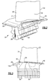
Figure 2 ,airfoil 30 has a leadingedge 31 and atrailing edge 33. Apressure side 32 of the airfoil is shown in this Figure. Acooling passage 34 is positioned on the pressure side of the airfoil, and in theplatform 28. Thecooling passage 34 extends to anoutlet 40, which, as will be explained below, sits on a suction side of theplatform 28. Theblade 24 includes aroot section 26 which is utilized to secure the blade within the rotor. In addition, a plurality ofcooling passages root 26 from a cooling air supply and upwardly into theairfoil 30, as known. - As shown in
Figure 3 , thecooling passage 34 has aninlet 42 for supplying air. As shown, theinlet 42 comes into theplatform 28 at a lower surface, and rearward of a leadingedge 100 of theplatform 28. Cooling air passes into aninlet 42, through thecooling passage 34, and outwardly of theoutlet 40 cooling theplatform 28. Theinlet 42 to thecooling passage 34 can be from any number of locations depending on the particular design, and the environment in which the component is to be utilized. A worker of ordinary skill in the art would be able to identify any number of potential sources of cooling air. As shown, a source of air communicates to the inlet. - As can be appreciated from
Figure 4 , theairfoil 30 has asuction side 50. Theoutlet 40 of thecooling passage 34 is on the suction side of the platform. Stated another way, should the airfoil be extended from thetrailing edge 33 to theedge 103 of theplatform 28, it will be at a position X. This could be defined as a dividing line between the pressure and suction sides of the platform. Theoutlet 40 is on the suction side. - In the
Figure 4 embodiment, thecooling passage 34 passes through the platform, and beneath thetrailing edge 33 before getting to theoutlet 40. As can be appreciated also from this Figure, theend 102 of the cooling passage curves away from theedge 103, before curving back toward theedge 103 and reachingoutlet 40. The curve shown at theend 102, and leading toward theoutlet 40, assists in directing the exiting air flow to line up with the main gas air flow through the gas turbine engine. However, a straight passage to the outlet may also be utilized. As shown, the cooling passage has a bulgedintermediate portion 400. The bulgedportion 400 increases the cooling surface area at a particular location along the path, and further allows better heat transfer characteristics. - Various cooling structures may be included in the
cooling passage 34. Pin fins, trip strips, guide vanes, pedestals, etc., may be placed within the passage to manage stress, gas flow, and heat transfer. As shown, a number ofpins 21 may be formed within thecooling passage 34 to increase the heat transfer effect. As mentioned, any number of other heat transfer shapes can be utilized, including arib 52 adjacent the outlet. Further, if there are localized hot spots, outlet holes can be formed either to the outer face of the platform, or to theouter edge 103, as deemed appropriate by the designer. Additionally, holes can be drilled from the underside of the platform to supply additional air to the passage. - As shown in
Figure 5 , asecond embodiment 124 hasplatform 128, andplatform cooling passage 134. Again, an extension from thetrailing edge 133 of theairfoil 130 reaches point X. Thecooling passage 134 passes around the airfoiltrailing edge 133, and theoutlet 152 of thecooling passage 134 is on the suction side of point X, and the suction side of theplatform 128. Stated another way, the cooling passage does not pass underneath the airfoil, but instead is positioned between thetrailing edge 133 and the side wall of the platform when passing from the pressure side to the suction side. - All of the above discussed cooling features, such as
features -
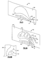
Figure 6A shows yet anotherembodiment 160 having aplatform 165, and anairfoil 162. Here, thecooling passage 166 has a serpentine path, including acurve 168 on the pressure side, which leads to a leadingedge extending portion 170, a crossingportion 172, aportion 174, which is now on the suction side, and which leads to afinal portion 176 leading to theoutlet 178. Again, theoutlet 178 is on the suction side, and on an opposed side of the point X from the inlet to thecooling passage 166. - In the
Figure 6A embodiment, acentral passage 164 in theairfoil 162 can be seen to have thecooling passage portion 172 passing underneath. - As shown in
Figure 6B , thepassage 172 preferably does not communicate with thepassage 164 when passing underneath thepassage 164. In addition, while theserpentine passage 166 is disclosed, a more direct route underneath the airfoil can also be utilized. - The inlet to the cooling passages in
Figures 4-6 may be positioned anywhere, as mentioned above. - An
embodiment 200 is shown inFigure 7 , wherein the cooling passage is incorporated into a static vane arrangement. As shown,vane airfoils platforms platform 204 will be a radially inner end wall when thevane embodiment 200 is mounted within an engine, while theplatform 202 will be radially outwardly. While a dual vane arrangement is shown, a single vane may also incorporate the cooling passage, as may any number of other static vane arrangements. - As shown in
Figure 8 , again, acooling passage 212 is formed on apressure side 210 of theairfoil 208. Theoutlet 214 is again on thesuction side 211, and on an opposed side of the point X from the inlet to thecore 212. - As can be appreciated from the several embodiments, the outlet is located on an outer face. The above is true of all of the embodiments. In the vane embodiments, the "outer face" is facing radially inwardly, but from a functional standpoint, the face of the platform from which the airfoil extends is the "outer face" for purposes of this application.
- The
cooling passages 34 may be formed from any suitable core material known in the art. For example, thecooling passage 34 may be formed from a refractory metal or metal alloy such as molybdenum or a molybdenum alloy. Alternatively, thecooling passage 34 may be formed from a ceramic or silica material. - The
cooling passage 34 can be formed by a lost core molding technique, as is known in the art. Alternatively, the passage can be created by welding a plate onto the part after the passage has been created by a molding technique. Any number of other ways of forming such internal structure can also be utilized. - The platform cooling passage provides shielding to the underplatform from hot gases. Shielding reduces heat pick-up in the rim, potentially improving rotor/seal/damper, etc. life. Shielding also reduces bulk panel temperatures, which increases creep life on the end wall.
- Although several embodiment of this invention have been disclosed, a worker of ordinary skill in this art would recognize that certain modifications would come within the scope of this invention. For that reason, the following claims should be studied to determine the true scope and content of this invention.
Claims (15)
- A gas turbine engine component (24; 124; 160; 200) comprising:a platform (28; 128; 165; 202), and an airfoil (30; 130; 162; 206) extending from said platform (28; 128; 165; 202), said platform (28; 128; 165; 202) having a pressure side (32) and a suction side (50); anda cooling passage (34; 134; 166; 212) located within said platform (28; 128; 165; 202), and extending along the pressure side of said platform (28; 128; 165; 202), and an outlet (40; 152; 178; 214) for air leaving said cooling passage (34; 134; 166; 212), said outlet being on the suction side of said platform (28; 128; 165; 202).
- The component as set forth in claim 1, wherein an extension of a trailing edge of said airfoil (30; 130; 162; 206) can be extended to a point on a side wall of said platform (28; 128; 165; 202), and said cooling passage (34; 134; 166; 212) is on one side of said point, and said outlet (40; 152; 178; 214) being on an opposed side.
- The component as set forth in claim 1 or 2, wherein said cooling passage (34, 166; 212) passes beneath a portion of said airfoil (30; 130; 210) between said inlet and said outlet.
- The component as set forth in claim 3, wherein said cooling passage (34) passes beneath a trailing edge (33) of said airfoil, and to said suction side.
- The component as set forth in claim 3, wherein said airfoil (166) has internal cooling passages (164), and said cooling passage (166) passes beneath one of said internal cooling passages (164) in said airfoil (166) before reaching said outlet (178) on said suction side.
- The component as set forth in claim 1 or 2, wherein said cooling passage (134) does not pass underneath said airfoil (130), but instead is positioned between a trailing edge (133) of said airfoil (130), and a side wall of said platform (128) when passing from said pressure side to said suction side.
- The component as set forth in any preceding claim, wherein an end of said cooling passage (34; 134; 166) leading to said outlet curves toward a first side wall of said platform (28; 128; 165), and then turns back to an opposed side wall of said platform.
- The component as set forth in any preceding claim, wherein said cooling passage (34; 134; 166) has a bulged intermediate portion (400) to increase heat transfer by increasing contact area between said cooling passage (34; 134; 166) and a portion of said platform (28; 128; 165).
- The component as set forth in any preceding claim, wherein elements (21; 136) are positioned within said cooling passage (34; 134; 166; 212).
- The component as set forth in any preceding claim, wherein said component is a turbine blade (24; 124; 160).
- The component as set forth in any of claims 1 to 9, wherein said component is a static vane (200).
- The component as set forth in claim 11, wherein said static vane (200) has a platform (200, 204) at both a radially outer edge and a radially inner edge.
- The component as set forth in claim 12, wherein said cooling passage (206) is located in said radially outer edge platform (202).
- The component as set forth in any preceding claim, wherein said outlet (40; 152; 178; 214) is at an outer face of said platform (28; 128; 165; 202).
- A gas turbine engine component comprising:a platform (28; 128; 165; 202), and an airfoil (30; 130; 162; 206) extending from said platform (28; 128; 165; 202), said platform (28; 128; 165; 202) having a pressure side (32) and a suction side (50); a cooling passage (34; 134; 166; 212) formed within said platform (28; 128; 165; 202), and extending along a pressure side of said platform (28; 128; 165; 202), and an outlet (40; 152; 178; 214) for air leaving said passage (34; 134; 166; 212), said outlet (40; 152; 178; 214) being on a suction side of said platform (28; 128; 165; 202); whereinan extension of a trailing edge of said airfoil (30; 130; 162; 206) can be extended to a point on said side wall of said platform and an inlet to said cooling passage (34; 134; 166; 212) is on one side of said point, and said outlet (40; 152; 178; 214) on an opposed side; andsaid outlet (40; 152; 178; 214) is at an outer face of said platform (28; 128; 165; 202).
Applications Claiming Priority (1)
| Application Number | Priority Date | Filing Date | Title |
|---|---|---|---|
| US12/623,666 US8356978B2 (en) | 2009-11-23 | 2009-11-23 | Turbine airfoil platform cooling core |
Publications (3)
| Publication Number | Publication Date |
|---|---|
| EP2325439A2 true EP2325439A2 (en) | 2011-05-25 |
| EP2325439A3 EP2325439A3 (en) | 2014-04-30 |
| EP2325439B1 EP2325439B1 (en) | 2018-02-28 |
Family
ID=43611936
Family Applications (1)
| Application Number | Title | Priority Date | Filing Date |
|---|---|---|---|
| EP10251976.6A Active EP2325439B1 (en) | 2009-11-23 | 2010-11-22 | Gas turbine engine component |
Country Status (2)
| Country | Link |
|---|---|
| US (1) | US8356978B2 (en) |
| EP (1) | EP2325439B1 (en) |
Families Citing this family (38)
| Publication number | Priority date | Publication date | Assignee | Title |
|---|---|---|---|---|
| US9109454B2 (en) | 2012-03-01 | 2015-08-18 | General Electric Company | Turbine bucket with pressure side cooling |
| US8974182B2 (en) | 2012-03-01 | 2015-03-10 | General Electric Company | Turbine bucket with a core cavity having a contoured turn |
| US9127561B2 (en) | 2012-03-01 | 2015-09-08 | General Electric Company | Turbine bucket with contoured internal rib |
| US9296039B2 (en) | 2012-04-24 | 2016-03-29 | United Technologies Corporation | Gas turbine engine airfoil impingement cooling |
| US9243502B2 (en) | 2012-04-24 | 2016-01-26 | United Technologies Corporation | Airfoil cooling enhancement and method of making the same |
| BR112014031269A2 (en) * | 2012-06-15 | 2017-08-08 | Gen Electric | turbine airfoil apparatus and method of forming a cooling orifice pattern. |
| US9021816B2 (en) * | 2012-07-02 | 2015-05-05 | United Technologies Corporation | Gas turbine engine turbine vane platform core |
| US9334755B2 (en) | 2012-09-28 | 2016-05-10 | United Technologies Corporation | Airfoil with variable trip strip height |
| US10533453B2 (en) | 2013-08-05 | 2020-01-14 | United Technologies Corporation | Engine component having platform with passageway |
| EP3047105B1 (en) | 2013-09-17 | 2021-06-09 | Raytheon Technologies Corporation | Platform cooling core for a gas turbine engine rotor blade |
| EP3084136B8 (en) * | 2013-12-17 | 2021-04-07 | Raytheon Technologies Corporation | Rotor blade and corresponding method of cooling a platform of a rotor blade |
| US10041374B2 (en) | 2014-04-04 | 2018-08-07 | United Technologies Corporation | Gas turbine engine component with platform cooling circuit |
| US9771816B2 (en) | 2014-05-07 | 2017-09-26 | General Electric Company | Blade cooling circuit feed duct, exhaust duct, and related cooling structure |
| US9638045B2 (en) | 2014-05-28 | 2017-05-02 | General Electric Company | Cooling structure for stationary blade |
| US9982542B2 (en) * | 2014-07-21 | 2018-05-29 | United Technologies Corporation | Airfoil platform impingement cooling holes |
| US10167726B2 (en) * | 2014-09-11 | 2019-01-01 | United Technologies Corporation | Component core with shaped edges |
| US10465523B2 (en) | 2014-10-17 | 2019-11-05 | United Technologies Corporation | Gas turbine component with platform cooling |
| US10041357B2 (en) | 2015-01-20 | 2018-08-07 | United Technologies Corporation | Cored airfoil platform with outlet slots |
| US10030523B2 (en) * | 2015-02-13 | 2018-07-24 | United Technologies Corporation | Article having cooling passage with undulating profile |
| US9988916B2 (en) | 2015-07-16 | 2018-06-05 | General Electric Company | Cooling structure for stationary blade |
| US9909436B2 (en) | 2015-07-16 | 2018-03-06 | General Electric Company | Cooling structure for stationary blade |
| US9822653B2 (en) | 2015-07-16 | 2017-11-21 | General Electric Company | Cooling structure for stationary blade |
| JP5905631B1 (en) * | 2015-09-15 | 2016-04-20 | 三菱日立パワーシステムズ株式会社 | Rotor blade, gas turbine provided with the same, and method of manufacturing rotor blade |
| US10280762B2 (en) * | 2015-11-19 | 2019-05-07 | United Technologies Corporation | Multi-chamber platform cooling structures |
| US10054055B2 (en) * | 2015-11-19 | 2018-08-21 | United Technology Corporation | Serpentine platform cooling structures |
| US10053989B2 (en) | 2015-12-21 | 2018-08-21 | General Electric Company | Cooling circuit for a multi-wall blade |
| US10030526B2 (en) * | 2015-12-21 | 2018-07-24 | General Electric Company | Platform core feed for a multi-wall blade |
| US10060269B2 (en) | 2015-12-21 | 2018-08-28 | General Electric Company | Cooling circuits for a multi-wall blade |
| US10119405B2 (en) | 2015-12-21 | 2018-11-06 | General Electric Company | Cooling circuit for a multi-wall blade |
| US10267162B2 (en) | 2016-08-18 | 2019-04-23 | General Electric Company | Platform core feed for a multi-wall blade |
| US10227877B2 (en) | 2016-08-18 | 2019-03-12 | General Electric Company | Cooling circuit for a multi-wall blade |
| US10221696B2 (en) | 2016-08-18 | 2019-03-05 | General Electric Company | Cooling circuit for a multi-wall blade |
| US10208607B2 (en) | 2016-08-18 | 2019-02-19 | General Electric Company | Cooling circuit for a multi-wall blade |
| US10208608B2 (en) | 2016-08-18 | 2019-02-19 | General Electric Company | Cooling circuit for a multi-wall blade |
| US11236625B2 (en) | 2017-06-07 | 2022-02-01 | General Electric Company | Method of making a cooled airfoil assembly for a turbine engine |
| US20190085706A1 (en) * | 2017-09-18 | 2019-03-21 | General Electric Company | Turbine engine airfoil assembly |
| US11021966B2 (en) * | 2019-04-24 | 2021-06-01 | Raytheon Technologies Corporation | Vane core assemblies and methods |
| US12173619B2 (en) * | 2022-05-02 | 2024-12-24 | Siemens Energy Global GmbH & Co. KG | Turbine component having platform cooling circuit |
Family Cites Families (27)
| Publication number | Priority date | Publication date | Assignee | Title |
|---|---|---|---|---|
| US4017209A (en) * | 1975-12-15 | 1977-04-12 | United Technologies Corporation | Turbine rotor construction |
| US4134709A (en) * | 1976-08-23 | 1979-01-16 | General Electric Company | Thermosyphon liquid cooled turbine bucket |
| US4712979A (en) | 1985-11-13 | 1987-12-15 | The United States Of America As Represented By The Secretary Of The Air Force | Self-retained platform cooling plate for turbine vane |
| US5813835A (en) * | 1991-08-19 | 1998-09-29 | The United States Of America As Represented By The Secretary Of The Air Force | Air-cooled turbine blade |
| GB9224241D0 (en) * | 1992-11-19 | 1993-01-06 | Bmw Rolls Royce Gmbh | A turbine blade arrangement |
| US5382135A (en) | 1992-11-24 | 1995-01-17 | United Technologies Corporation | Rotor blade with cooled integral platform |
| US5344283A (en) | 1993-01-21 | 1994-09-06 | United Technologies Corporation | Turbine vane having dedicated inner platform cooling |
| US5413458A (en) | 1994-03-29 | 1995-05-09 | United Technologies Corporation | Turbine vane with a platform cavity having a double feed for cooling fluid |
| KR100364183B1 (en) | 1994-10-31 | 2003-02-19 | 웨스팅하우스 일렉트릭 코포레이션 | Gas turbine blade with a cooled platform |
| US5513955A (en) | 1994-12-14 | 1996-05-07 | United Technologies Corporation | Turbine engine rotor blade platform seal |
| US5711650A (en) | 1996-10-04 | 1998-01-27 | Pratt & Whitney Canada, Inc. | Gas turbine airfoil cooling |
| FR2758855B1 (en) | 1997-01-30 | 1999-02-26 | Snecma | VENTILATION SYSTEM FOR MOBILE VANE PLATFORMS |
| US5848876A (en) | 1997-02-11 | 1998-12-15 | Mitsubishi Heavy Industries, Ltd. | Cooling system for cooling platform of gas turbine moving blade |
| JP3758792B2 (en) | 1997-02-25 | 2006-03-22 | 三菱重工業株式会社 | Gas turbine rotor platform cooling mechanism |
| CA2262064C (en) * | 1998-02-23 | 2002-09-03 | Mitsubishi Heavy Industries, Ltd. | Gas turbine moving blade platform |
| US6190130B1 (en) * | 1998-03-03 | 2001-02-20 | Mitsubishi Heavy Industries, Ltd. | Gas turbine moving blade platform |
| US6210111B1 (en) | 1998-12-21 | 2001-04-03 | United Technologies Corporation | Turbine blade with platform cooling |
| JP2001021245A (en) | 1999-07-09 | 2001-01-26 | Irie Koken Kk | Material and device for cold storage |
| US6254333B1 (en) * | 1999-08-02 | 2001-07-03 | United Technologies Corporation | Method for forming a cooling passage and for cooling a turbine section of a rotary machine |
| FR2810365B1 (en) | 2000-06-15 | 2002-10-11 | Snecma Moteurs | SYSTEM FOR VENTILATION OF A PAIR OF JUXTAPOSED DAWN PLATFORMS |
| DE10064265A1 (en) | 2000-12-22 | 2002-07-04 | Alstom Switzerland Ltd | Device and method for cooling a platform of a turbine blade |
| RU2271454C2 (en) | 2000-12-28 | 2006-03-10 | Альстом Текнолоджи Лтд | Making of platforms in straight-flow axial gas turbine with improved cooling of wall sections and method of decreasing losses through clearances |
| GB2395987B (en) | 2002-12-02 | 2005-12-21 | Alstom | Turbine blade with cooling bores |
| US6945749B2 (en) | 2003-09-12 | 2005-09-20 | Siemens Westinghouse Power Corporation | Turbine blade platform cooling system |
| US7186089B2 (en) | 2004-11-04 | 2007-03-06 | Siemens Power Generation, Inc. | Cooling system for a platform of a turbine blade |
| US7255536B2 (en) * | 2005-05-23 | 2007-08-14 | United Technologies Corporation | Turbine airfoil platform cooling circuit |
| US7309212B2 (en) | 2005-11-21 | 2007-12-18 | General Electric Company | Gas turbine bucket with cooled platform leading edge and method of cooling platform leading edge |
-
2009
- 2009-11-23 US US12/623,666 patent/US8356978B2/en active Active
-
2010
- 2010-11-22 EP EP10251976.6A patent/EP2325439B1/en active Active
Non-Patent Citations (1)
| Title |
|---|
| None |
Also Published As
| Publication number | Publication date |
|---|---|
| EP2325439B1 (en) | 2018-02-28 |
| US8356978B2 (en) | 2013-01-22 |
| US20110123310A1 (en) | 2011-05-26 |
| EP2325439A3 (en) | 2014-04-30 |
Similar Documents
| Publication | Publication Date | Title |
|---|---|---|
| EP2325439B1 (en) | Gas turbine engine component | |
| EP2325440B1 (en) | Serpentine cored airfoil with body microcircuits | |
| US6769878B1 (en) | Turbine blade airfoil | |
| US9279331B2 (en) | Gas turbine engine airfoil with dirt purge feature and core for making same | |
| US7255536B2 (en) | Turbine airfoil platform cooling circuit | |
| EP1918522B1 (en) | Component for a gas turbine engine | |
| US7118329B2 (en) | Tip sealing for a turbine rotor blade | |
| EP1273758B1 (en) | Method and device for airfoil film cooling | |
| CN101025091B (en) | Bucket platform cooling circuit and method | |
| EP2141327B1 (en) | Aerofoils and corresponding rotor assembly | |
| CN101429875B (en) | turbine blade with end shield of Z-notch shape | |
| US8011888B1 (en) | Turbine blade with serpentine cooling | |
| EP2374997B1 (en) | Component for a gas turbine engine | |
| EP2885504B1 (en) | Airfoil and corresponding gas turbine engine | |
| US9429027B2 (en) | Turbine airfoil tip shelf and squealer pocket cooling | |
| JP2001090501A (en) | Gas turbine blade with impingement cooling platform | |
| CN101769171A (en) | Turbine rotor blade tips that discourage cross-flow | |
| EP1788195A3 (en) | Blades for gas turbine engines | |
| US20070041835A1 (en) | Turbine blade including revised trailing edge cooling | |
| CN107084004A (en) | Impact opening for turbine engine components | |
| EP2634370B1 (en) | Turbine bucket with a core cavity having a contoured turn | |
| EP3301262B1 (en) | Blade | |
| EP2998511A1 (en) | Cooling passage with surface features | |
| EP2949868A1 (en) | A gas turbine blade tip comprising a gutter with decreased floor depth | |
| EP3118413B1 (en) | Turbine airfoil tip shelf and squealer pocket cooling |
Legal Events
| Date | Code | Title | Description |
|---|---|---|---|
| PUAI | Public reference made under article 153(3) epc to a published international application that has entered the european phase |
Free format text: ORIGINAL CODE: 0009012 |
|
| AK | Designated contracting states |
Kind code of ref document: A2 Designated state(s): AL AT BE BG CH CY CZ DE DK EE ES FI FR GB GR HR HU IE IS IT LI LT LU LV MC MK MT NL NO PL PT RO RS SE SI SK SM TR |
|
| AX | Request for extension of the european patent |
Extension state: BA ME |
|
| PUAL | Search report despatched |
Free format text: ORIGINAL CODE: 0009013 |
|
| AK | Designated contracting states |
Kind code of ref document: A3 Designated state(s): AL AT BE BG CH CY CZ DE DK EE ES FI FR GB GR HR HU IE IS IT LI LT LU LV MC MK MT NL NO PL PT RO RS SE SI SK SM TR |
|
| AX | Request for extension of the european patent |
Extension state: BA ME |
|
| RIC1 | Information provided on ipc code assigned before grant |
Ipc: F01D 5/18 20060101ALI20140326BHEP Ipc: F01D 5/08 20060101AFI20140326BHEP Ipc: F01D 9/02 20060101ALI20140326BHEP |
|
| 17P | Request for examination filed |
Effective date: 20141030 |
|
| RBV | Designated contracting states (corrected) |
Designated state(s): AL AT BE BG CH CY CZ DE DK EE ES FI FR GB GR HR HU IE IS IT LI LT LU LV MC MK MT NL NO PL PT RO RS SE SI SK SM TR |
|
| RAP1 | Party data changed (applicant data changed or rights of an application transferred) |
Owner name: UNITED TECHNOLOGIES CORPORATION |
|
| GRAP | Despatch of communication of intention to grant a patent |
Free format text: ORIGINAL CODE: EPIDOSNIGR1 |
|
| STAA | Information on the status of an ep patent application or granted ep patent |
Free format text: STATUS: GRANT OF PATENT IS INTENDED |
|
| INTG | Intention to grant announced |
Effective date: 20170914 |
|
| GRAS | Grant fee paid |
Free format text: ORIGINAL CODE: EPIDOSNIGR3 |
|
| GRAA | (expected) grant |
Free format text: ORIGINAL CODE: 0009210 |
|
| STAA | Information on the status of an ep patent application or granted ep patent |
Free format text: STATUS: THE PATENT HAS BEEN GRANTED |
|
| AK | Designated contracting states |
Kind code of ref document: B1 Designated state(s): AL AT BE BG CH CY CZ DE DK EE ES FI FR GB GR HR HU IE IS IT LI LT LU LV MC MK MT NL NO PL PT RO RS SE SI SK SM TR |
|
| REG | Reference to a national code |
Ref country code: GB Ref legal event code: FG4D Ref country code: CH Ref legal event code: EP |
|
| REG | Reference to a national code |
Ref country code: AT Ref legal event code: REF Ref document number: 974369 Country of ref document: AT Kind code of ref document: T Effective date: 20180315 |
|
| REG | Reference to a national code |
Ref country code: IE Ref legal event code: FG4D |
|
| REG | Reference to a national code |
Ref country code: DE Ref legal event code: R096 Ref document number: 602010048786 Country of ref document: DE |
|
| REG | Reference to a national code |
Ref country code: NL Ref legal event code: MP Effective date: 20180228 |
|
| REG | Reference to a national code |
Ref country code: LT Ref legal event code: MG4D |
|
| REG | Reference to a national code |
Ref country code: AT Ref legal event code: MK05 Ref document number: 974369 Country of ref document: AT Kind code of ref document: T Effective date: 20180228 |
|
| PG25 | Lapsed in a contracting state [announced via postgrant information from national office to epo] |
Ref country code: ES Free format text: LAPSE BECAUSE OF FAILURE TO SUBMIT A TRANSLATION OF THE DESCRIPTION OR TO PAY THE FEE WITHIN THE PRESCRIBED TIME-LIMIT Effective date: 20180228 Ref country code: NL Free format text: LAPSE BECAUSE OF FAILURE TO SUBMIT A TRANSLATION OF THE DESCRIPTION OR TO PAY THE FEE WITHIN THE PRESCRIBED TIME-LIMIT Effective date: 20180228 Ref country code: LT Free format text: LAPSE BECAUSE OF FAILURE TO SUBMIT A TRANSLATION OF THE DESCRIPTION OR TO PAY THE FEE WITHIN THE PRESCRIBED TIME-LIMIT Effective date: 20180228 Ref country code: HR Free format text: LAPSE BECAUSE OF FAILURE TO SUBMIT A TRANSLATION OF THE DESCRIPTION OR TO PAY THE FEE WITHIN THE PRESCRIBED TIME-LIMIT Effective date: 20180228 Ref country code: FI Free format text: LAPSE BECAUSE OF FAILURE TO SUBMIT A TRANSLATION OF THE DESCRIPTION OR TO PAY THE FEE WITHIN THE PRESCRIBED TIME-LIMIT Effective date: 20180228 Ref country code: NO Free format text: LAPSE BECAUSE OF FAILURE TO SUBMIT A TRANSLATION OF THE DESCRIPTION OR TO PAY THE FEE WITHIN THE PRESCRIBED TIME-LIMIT Effective date: 20180528 Ref country code: CY Free format text: LAPSE BECAUSE OF FAILURE TO SUBMIT A TRANSLATION OF THE DESCRIPTION OR TO PAY THE FEE WITHIN THE PRESCRIBED TIME-LIMIT Effective date: 20180228 |
|
| PG25 | Lapsed in a contracting state [announced via postgrant information from national office to epo] |
Ref country code: LV Free format text: LAPSE BECAUSE OF FAILURE TO SUBMIT A TRANSLATION OF THE DESCRIPTION OR TO PAY THE FEE WITHIN THE PRESCRIBED TIME-LIMIT Effective date: 20180228 Ref country code: SE Free format text: LAPSE BECAUSE OF FAILURE TO SUBMIT A TRANSLATION OF THE DESCRIPTION OR TO PAY THE FEE WITHIN THE PRESCRIBED TIME-LIMIT Effective date: 20180228 Ref country code: GR Free format text: LAPSE BECAUSE OF FAILURE TO SUBMIT A TRANSLATION OF THE DESCRIPTION OR TO PAY THE FEE WITHIN THE PRESCRIBED TIME-LIMIT Effective date: 20180529 Ref country code: RS Free format text: LAPSE BECAUSE OF FAILURE TO SUBMIT A TRANSLATION OF THE DESCRIPTION OR TO PAY THE FEE WITHIN THE PRESCRIBED TIME-LIMIT Effective date: 20180228 Ref country code: AT Free format text: LAPSE BECAUSE OF FAILURE TO SUBMIT A TRANSLATION OF THE DESCRIPTION OR TO PAY THE FEE WITHIN THE PRESCRIBED TIME-LIMIT Effective date: 20180228 Ref country code: BG Free format text: LAPSE BECAUSE OF FAILURE TO SUBMIT A TRANSLATION OF THE DESCRIPTION OR TO PAY THE FEE WITHIN THE PRESCRIBED TIME-LIMIT Effective date: 20180528 |
|
| REG | Reference to a national code |
Ref country code: FR Ref legal event code: PLFP Year of fee payment: 9 |
|
| PG25 | Lapsed in a contracting state [announced via postgrant information from national office to epo] |
Ref country code: IT Free format text: LAPSE BECAUSE OF FAILURE TO SUBMIT A TRANSLATION OF THE DESCRIPTION OR TO PAY THE FEE WITHIN THE PRESCRIBED TIME-LIMIT Effective date: 20180228 Ref country code: AL Free format text: LAPSE BECAUSE OF FAILURE TO SUBMIT A TRANSLATION OF THE DESCRIPTION OR TO PAY THE FEE WITHIN THE PRESCRIBED TIME-LIMIT Effective date: 20180228 Ref country code: EE Free format text: LAPSE BECAUSE OF FAILURE TO SUBMIT A TRANSLATION OF THE DESCRIPTION OR TO PAY THE FEE WITHIN THE PRESCRIBED TIME-LIMIT Effective date: 20180228 Ref country code: PL Free format text: LAPSE BECAUSE OF FAILURE TO SUBMIT A TRANSLATION OF THE DESCRIPTION OR TO PAY THE FEE WITHIN THE PRESCRIBED TIME-LIMIT Effective date: 20180228 Ref country code: RO Free format text: LAPSE BECAUSE OF FAILURE TO SUBMIT A TRANSLATION OF THE DESCRIPTION OR TO PAY THE FEE WITHIN THE PRESCRIBED TIME-LIMIT Effective date: 20180228 |
|
| REG | Reference to a national code |
Ref country code: DE Ref legal event code: R097 Ref document number: 602010048786 Country of ref document: DE |
|
| PG25 | Lapsed in a contracting state [announced via postgrant information from national office to epo] |
Ref country code: DK Free format text: LAPSE BECAUSE OF FAILURE TO SUBMIT A TRANSLATION OF THE DESCRIPTION OR TO PAY THE FEE WITHIN THE PRESCRIBED TIME-LIMIT Effective date: 20180228 Ref country code: SM Free format text: LAPSE BECAUSE OF FAILURE TO SUBMIT A TRANSLATION OF THE DESCRIPTION OR TO PAY THE FEE WITHIN THE PRESCRIBED TIME-LIMIT Effective date: 20180228 Ref country code: CZ Free format text: LAPSE BECAUSE OF FAILURE TO SUBMIT A TRANSLATION OF THE DESCRIPTION OR TO PAY THE FEE WITHIN THE PRESCRIBED TIME-LIMIT Effective date: 20180228 Ref country code: SK Free format text: LAPSE BECAUSE OF FAILURE TO SUBMIT A TRANSLATION OF THE DESCRIPTION OR TO PAY THE FEE WITHIN THE PRESCRIBED TIME-LIMIT Effective date: 20180228 |
|
| PLBE | No opposition filed within time limit |
Free format text: ORIGINAL CODE: 0009261 |
|
| STAA | Information on the status of an ep patent application or granted ep patent |
Free format text: STATUS: NO OPPOSITION FILED WITHIN TIME LIMIT |
|
| 26N | No opposition filed |
Effective date: 20181129 |
|
| PG25 | Lapsed in a contracting state [announced via postgrant information from national office to epo] |
Ref country code: SI Free format text: LAPSE BECAUSE OF FAILURE TO SUBMIT A TRANSLATION OF THE DESCRIPTION OR TO PAY THE FEE WITHIN THE PRESCRIBED TIME-LIMIT Effective date: 20180228 |
|
| REG | Reference to a national code |
Ref country code: CH Ref legal event code: PL |
|
| PG25 | Lapsed in a contracting state [announced via postgrant information from national office to epo] |
Ref country code: MC Free format text: LAPSE BECAUSE OF FAILURE TO SUBMIT A TRANSLATION OF THE DESCRIPTION OR TO PAY THE FEE WITHIN THE PRESCRIBED TIME-LIMIT Effective date: 20180228 Ref country code: LU Free format text: LAPSE BECAUSE OF NON-PAYMENT OF DUE FEES Effective date: 20181122 |
|
| REG | Reference to a national code |
Ref country code: BE Ref legal event code: MM Effective date: 20181130 |
|
| REG | Reference to a national code |
Ref country code: IE Ref legal event code: MM4A |
|
| PG25 | Lapsed in a contracting state [announced via postgrant information from national office to epo] |
Ref country code: LI Free format text: LAPSE BECAUSE OF NON-PAYMENT OF DUE FEES Effective date: 20181130 Ref country code: CH Free format text: LAPSE BECAUSE OF NON-PAYMENT OF DUE FEES Effective date: 20181130 |
|
| PG25 | Lapsed in a contracting state [announced via postgrant information from national office to epo] |
Ref country code: IE Free format text: LAPSE BECAUSE OF NON-PAYMENT OF DUE FEES Effective date: 20181122 |
|
| PG25 | Lapsed in a contracting state [announced via postgrant information from national office to epo] |
Ref country code: BE Free format text: LAPSE BECAUSE OF NON-PAYMENT OF DUE FEES Effective date: 20181130 |
|
| PG25 | Lapsed in a contracting state [announced via postgrant information from national office to epo] |
Ref country code: MT Free format text: LAPSE BECAUSE OF NON-PAYMENT OF DUE FEES Effective date: 20181122 |
|
| PG25 | Lapsed in a contracting state [announced via postgrant information from national office to epo] |
Ref country code: TR Free format text: LAPSE BECAUSE OF FAILURE TO SUBMIT A TRANSLATION OF THE DESCRIPTION OR TO PAY THE FEE WITHIN THE PRESCRIBED TIME-LIMIT Effective date: 20180228 |
|
| PG25 | Lapsed in a contracting state [announced via postgrant information from national office to epo] |
Ref country code: PT Free format text: LAPSE BECAUSE OF FAILURE TO SUBMIT A TRANSLATION OF THE DESCRIPTION OR TO PAY THE FEE WITHIN THE PRESCRIBED TIME-LIMIT Effective date: 20180228 |
|
| PG25 | Lapsed in a contracting state [announced via postgrant information from national office to epo] |
Ref country code: HU Free format text: LAPSE BECAUSE OF FAILURE TO SUBMIT A TRANSLATION OF THE DESCRIPTION OR TO PAY THE FEE WITHIN THE PRESCRIBED TIME-LIMIT; INVALID AB INITIO Effective date: 20101122 Ref country code: MK Free format text: LAPSE BECAUSE OF NON-PAYMENT OF DUE FEES Effective date: 20180228 |
|
| PG25 | Lapsed in a contracting state [announced via postgrant information from national office to epo] |
Ref country code: IS Free format text: LAPSE BECAUSE OF FAILURE TO SUBMIT A TRANSLATION OF THE DESCRIPTION OR TO PAY THE FEE WITHIN THE PRESCRIBED TIME-LIMIT Effective date: 20180628 |
|
| REG | Reference to a national code |
Ref country code: DE Ref legal event code: R081 Ref document number: 602010048786 Country of ref document: DE Owner name: RAYTHEON TECHNOLOGIES CORPORATION (N.D.GES.D.S, US Free format text: FORMER OWNER: UNITED TECHNOLOGIES CORPORATION, FARMINGTON, CONN., US Ref country code: DE Ref legal event code: R081 Ref document number: 602010048786 Country of ref document: DE Owner name: RTX CORPORATION (N.D.GES.D. STAATES DELAWARE),, US Free format text: FORMER OWNER: UNITED TECHNOLOGIES CORPORATION, FARMINGTON, CONN., US |
|
| P01 | Opt-out of the competence of the unified patent court (upc) registered |
Effective date: 20230519 |
|
| REG | Reference to a national code |
Ref country code: DE Ref legal event code: R081 Ref document number: 602010048786 Country of ref document: DE Owner name: RTX CORPORATION (N.D.GES.D. STAATES DELAWARE),, US Free format text: FORMER OWNER: RAYTHEON TECHNOLOGIES CORPORATION (N.D.GES.D.STAATES DELAWARE), ARLINGTON, VA, US |
|
| PGFP | Annual fee paid to national office [announced via postgrant information from national office to epo] |
Ref country code: DE Payment date: 20251022 Year of fee payment: 16 |
|
| PGFP | Annual fee paid to national office [announced via postgrant information from national office to epo] |
Ref country code: GB Payment date: 20251023 Year of fee payment: 16 |
|
| PGFP | Annual fee paid to national office [announced via postgrant information from national office to epo] |
Ref country code: FR Payment date: 20251022 Year of fee payment: 16 |