EP2325416A1 - Perimeter protection system for construction sites - Google Patents
Perimeter protection system for construction sites Download PDFInfo
- Publication number
- EP2325416A1 EP2325416A1 EP09382250A EP09382250A EP2325416A1 EP 2325416 A1 EP2325416 A1 EP 2325416A1 EP 09382250 A EP09382250 A EP 09382250A EP 09382250 A EP09382250 A EP 09382250A EP 2325416 A1 EP2325416 A1 EP 2325416A1
- Authority
- EP
- European Patent Office
- Prior art keywords
- guides
- mentioned
- slab
- construction sites
- support
- Prior art date
- Legal status (The legal status is an assumption and is not a legal conclusion. Google has not performed a legal analysis and makes no representation as to the accuracy of the status listed.)
- Granted
Links
Images


Classifications
-
- E—FIXED CONSTRUCTIONS
- E04—BUILDING
- E04G—SCAFFOLDING; FORMS; SHUTTERING; BUILDING IMPLEMENTS OR AIDS, OR THEIR USE; HANDLING BUILDING MATERIALS ON THE SITE; REPAIRING, BREAKING-UP OR OTHER WORK ON EXISTING BUILDINGS
- E04G21/00—Preparing, conveying, or working-up building materials or building elements in situ; Other devices or measures for constructional work
- E04G21/32—Safety or protective measures for persons during the construction of buildings
- E04G21/3204—Safety or protective measures for persons during the construction of buildings against falling down
- E04G21/3223—Means supported by building floors or flat roofs, e.g. safety railings
-
- E—FIXED CONSTRUCTIONS
- E04—BUILDING
- E04G—SCAFFOLDING; FORMS; SHUTTERING; BUILDING IMPLEMENTS OR AIDS, OR THEIR USE; HANDLING BUILDING MATERIALS ON THE SITE; REPAIRING, BREAKING-UP OR OTHER WORK ON EXISTING BUILDINGS
- E04G5/00—Component parts or accessories for scaffolds
- E04G5/14—Railings
- E04G2005/148—Railings latticed or netted
Definitions
- the invention is comprised in the field of the safety systems used in the construction of buildings, and more specifically, to the systems which are arranged in the perimeter of the building to prevent the fall of objects and persons.
- the gallows system is a system comprising two rockers fixed to the slab, between which a net is placed which will be hung like a bag to collect a possible fall of persons or materials. This bag is fixed at its lower part to the slab.
- the tray type system is a system of horizontal protection in which a net is placed between the horizontally arranged rockers.
- an edge protection system must be used.
- the systems normally used consist of vertical standards arranged at a certain distance between them, between which horizontal tubes or wood pieces are placed and fixed like a rail.
- the system described in the present invention is of the screen type and, it allows simultaneously protecting several scaffolding floors, i.e., its progression is independent of the growth of the building, therefore it is not necessary to dismantle the assembly to protect higher floors. Furthermore, the system object of the invention is assembled quickly and simply.
- perimeter protection systems for construction sites comprise:
- the system, object of the invention allows obtaining enclosure segments which are formed from guides, some of which are attached to a slab through the support means and others are coupled to one another through attachment means to form support columns such that the vertical progression of the system is allowed.
- the guides comprise at least a mast and a plurality of crosspieces attached to the mast.
- the protection means are formed by protection panels comprising a pair of horizontal beams configured to be coupled to the crosspieces of the guides through attachment elements, for example hoops and a net fixed between the mentioned beams.
- Each enclosure segment can be formed from guides vertically assembled to shape at least two support columns, the mentioned support columns having a height which allows assembling three protection panels thereto, such that the first and third panel form the handrails of a first slab and a second slab, successive to the first one, and the second panel is arranged between the mentioned first and third panel and is configured for closing the gap existing between the first and third protection panel.
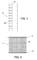
- the guides can have a shape similar to that of a ladder, i.e., they can be formed by two masts and a plurality of crosspieces attached to the mentioned masts. This particular shape of the guides provides the structure with greater robustness.
- the attachment means can comprise, for example, linking elements configured to be housed inside the masts of two vertically arranged guides.
- These linking elements can be independent attachment profiles, wherein a first end of the mentioned profile is housed inside the mast of a first guide and a second end of the mentioned profile is housed inside the mast of a second guide contiguous to the first one, such that the two guides are vertically coupled.
- the sequence of vertical coupling between guides can be the following one, attachment profiles are introduced in each mast of first guides, being secured, for example, by means of screws, a first end of the attachment profile being housed inside the masts of these first guides. The end which has remained free, i.e., which has not been housed in the masts of the first guides, is then introduced in the masts of second guides, this second end being housed inside the masts of the second guides. Side reinforcing profiles fixed in each mast by means of, for example, threaded rods can be used to give a higher consistency to this attachment.
- each inclosure segment can be formed from at least two support columns between which three panels are assembled, each of these panels having a clear and specific function.
- the first panel i.e., the first assembly of net and beams, will act as a handrail or rail of the first scaffolding.
- the second panel will act as a screen net, allowing furthermore a space between its upper part and the lower part of the third panel which will allow the scaffolder to use the current scaffolding systems, without the net or the system getting in his way.
- the third panel will carried out the function of screen net initially but in a second phase will act as a handrail or rail of the following slab.
- the support means can comprise a horizontal element configured to be anchored to a slab and a vertical element, arranged in an end of the mentioned horizontal element, the mentioned vertical element comprising at least two securing profiles configured to serve as support for at least two crosspieces of the guides, such that the mentioned guides are in a vertical position.
- the vertical element can comprise at least two profiles, which can have a U shape, open at the upper part and configured to entrap the masts of the guides, such that the mentioned guides are in a vertical position and furthermore comprise two support bars which are fixed to the slab.
- any of these support means are used to fix first guides to a slab, the rest of the guides will be coupled to one another to form support columns. However, it may be necessary in certain occasions to use another support means in upper floors to fix other guides.
- Figure 7 shows an enclosure segment (1) which is formed from guides (22) vertically assembled to one another to form two support columns (2).
- the support columns have a height suitable to allow assembling three panels (4).
- the panels (4) comprise a pair of beams (41) configured to be coupled to crosspieces (222) of the guides (22) and a net (42) fixed between the mentioned beams (41).
- the first and third panel (4) form the handrails of a first slab and a second slab which is successive to the first one and the second panel (4) which is arranged between the mentioned first and third panel (4) is configured to cover the gap existing between them.
- the assembly of an enclosure segment (1) starts with the attachment of a pair of guides (22) arranged in parallel, to a first slab through support means (31,32).
- a first panel (4) is subsequently placed between the mentioned guides (22), fixing the beams (41) of the panels (4) to the crosspieces (222) of the guides (22), so that the mentioned first panel (4) acts as a rail of the first slab.
- a third panel (4) will subsequently be placed which will be separated from the second panel (4) a distance suitable for allowing the scaffolding of the upper floor to come out without the system (1) interfering in the scaffolding tasks.
- This third panel (4) will act as a safety rail for the upper floor, which has not been made yet.
- FIG 4 shows support means (31) which will fix guides (22) to a slab.
- these support means (31) are formed by a horizontal element (311) which is fixed to the slab and a vertical element (312) which is arranged in an end of the mentioned horizontal element (311), forming an "L".
- the vertical element (312) incorporates two U-shaped securing profiles (313) open at the upper part and which are configured to serve as support for crosspieces (221) comprised by the guides (22). Since the crosspieces (221) are supported in the securing profiles (313), the guides (22) are in a vertical position to allow the coupling of more guides (22) and thus form support columns (2).
- first guides (22) are coupled to these support means (31), other guides (22) will be directly coupled to one another, i.e., normally, these fixing means (31) are only used in a first slab. Nevertheless, it may be necessary to place another support means (31) in one of the upper floors.
- fix them to the slab by means of a securing omega clamp, for example.
- FIG. 5 shows other alternative of the support means.
- (32) which can comprise two profiles (321) fitting with the masts (222) of the guides (22), so that the mentioned guides (22) are in a vertical position.
- These profiles (321) can have a U shape and be open at the upper part.
- they can comprise two support bars (322) which are anchored to the slab.
- attachment means (5) which allow the vertical progression of the system are used.
- These attachment means can be, for example, independent profiles which will be housed inside the masts (221) of two contiguous guides (22).
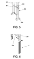
- FIG 6 shows these profiles and, specifically, an attachment profile inserted in the mast (221) of a guide (22) and another profile, which will be introduced in other mast (221) of this same guide (22) are seen.
- This Figure 6 shows how the attachment profile is partially housed in the mast (221), since an end of the mentioned profile projects from the mast (221).
- To couple a second guide (22) to the first one it is only necessary to introduce the end of the projecting attachment profile through the mast (221) of a second guide (22), such that the ends of the masts (221) of the two guides (22) are in contact.
- screws can be used to fix the profiles to the masts (221).
- the attachment joint can be reinforced by means of a reinforcing profile with a contour similar to that of the mast (221), which is fixed to the masts (221) of the guides (22) in the area next to the attachment joint.
Landscapes
- Engineering & Computer Science (AREA)
- Architecture (AREA)
- Mechanical Engineering (AREA)
- Civil Engineering (AREA)
- Structural Engineering (AREA)
- Emergency Lowering Means (AREA)
Abstract
Description
- The invention is comprised in the field of the safety systems used in the construction of buildings, and more specifically, to the systems which are arranged in the perimeter of the building to prevent the fall of objects and persons.
- There are multiple systems to prevent the fall of persons or materials from a certain height, the most used being the simultaneous placement of gallows or tray type safety nets together with a rail type protection of the edge.
- The gallows system is a system comprising two rockers fixed to the slab, between which a net is placed which will be hung like a bag to collect a possible fall of persons or materials. This bag is fixed at its lower part to the slab.
- The tray type system is a system of horizontal protection in which a net is placed between the horizontally arranged rockers.
- Simultaneously to the use of any of these systems of nets, an edge protection system must be used. In this case the systems normally used consist of vertical standards arranged at a certain distance between them, between which horizontal tubes or wood pieces are placed and fixed like a rail.
- Another type of system is, for example, the system described in patent
US 4 129 197 , which relates to a safety system for scaffolding. This system is formed by a series of vertical standards, of a certain length, which are fixed to the bottom of each scaffolding floor and between which a rectangular structure like a protection screen is arranged. With this system, the scaffolding floor on which work is being carried out is protected, and, once the tasks have finished, the structure is lifted, by means of a crane, to the following scaffolding floor. Therefore, this type of system does not allow simultaneously and quickly protecting several scaffolding floors, since it grows progressively with the growth of the building. - The system described in the present invention is of the screen type and, it allows simultaneously protecting several scaffolding floors, i.e., its progression is independent of the growth of the building, therefore it is not necessary to dismantle the assembly to protect higher floors. Furthermore, the system object of the invention is assembled quickly and simply.
- In general, the perimeter protection systems for construction sites comprise:
- guides suitable for being arranged around the perimeter of a building,
- support means configured for fixing the mentioned guides to a support surface of the mentioned building,
- protection means fixed to the mentioned guides. These protection means are usually of the previously mentioned type, i.e., safety nets and/or rails,
- The system, object of the invention, allows obtaining enclosure segments which are formed from guides, some of which are attached to a slab through the support means and others are coupled to one another through attachment means to form support columns such that the vertical progression of the system is allowed. The guides comprise at least a mast and a plurality of crosspieces attached to the mast. The protection means are formed by protection panels comprising a pair of horizontal beams configured to be coupled to the crosspieces of the guides through attachment elements, for example hoops and a net fixed between the mentioned beams.
- Each enclosure segment can be formed from guides vertically assembled to shape at least two support columns, the mentioned support columns having a height which allows assembling three protection panels thereto, such that the first and third panel form the handrails of a first slab and a second slab, successive to the first one, and the second panel is arranged between the mentioned first and third panel and is configured for closing the gap existing between the first and third protection panel.
- The guides can have a shape similar to that of a ladder, i.e., they can be formed by two masts and a plurality of crosspieces attached to the mentioned masts. This particular shape of the guides provides the structure with greater robustness.
- In order for the coupling between guides to be carried out quickly and simply, the attachment means can comprise, for example, linking elements configured to be housed inside the masts of two vertically arranged guides. These linking elements can be independent attachment profiles, wherein a first end of the mentioned profile is housed inside the mast of a first guide and a second end of the mentioned profile is housed inside the mast of a second guide contiguous to the first one, such that the two guides are vertically coupled.
- The sequence of vertical coupling between guides can be the following one, attachment profiles are introduced in each mast of first guides, being secured, for example, by means of screws, a first end of the attachment profile being housed inside the masts of these first guides. The end which has remained free, i.e., which has not been housed in the masts of the first guides, is then introduced in the masts of second guides, this second end being housed inside the masts of the second guides. Side reinforcing profiles fixed in each mast by means of, for example, threaded rods can be used to give a higher consistency to this attachment.
- As has been previously indicated, each inclosure segment can be formed from at least two support columns between which three panels are assembled, each of these panels having a clear and specific function. The first panel, i.e., the first assembly of net and beams, will act as a handrail or rail of the first scaffolding. The second panel will act as a screen net, allowing furthermore a space between its upper part and the lower part of the third panel which will allow the scaffolder to use the current scaffolding systems, without the net or the system getting in his way. The third panel will carried out the function of screen net initially but in a second phase will act as a handrail or rail of the following slab.
- Different alternatives, depending on the structure of the building, can be used to fix the guides to a support surface.
- The support means can comprise a horizontal element configured to be anchored to a slab and a vertical element, arranged in an end of the mentioned horizontal element, the mentioned vertical element comprising at least two securing profiles configured to serve as support for at least two crosspieces of the guides, such that the mentioned guides are in a vertical position.
- On the other hand, the vertical element can comprise at least two profiles, which can have a U shape, open at the upper part and configured to entrap the masts of the guides, such that the mentioned guides are in a vertical position and furthermore comprise two support bars which are fixed to the slab.
- Normally, any of these support means are used to fix first guides to a slab, the rest of the guides will be coupled to one another to form support columns. However, it may be necessary in certain occasions to use another support means in upper floors to fix other guides.
- To give consistency to the assembly and prevent the buckling of the columns, especially the upper ones, it is possible to fix them to the slab, for example, by means of a securing omega clamp which secures the guides to the slab and anchors which secure the crosspieces to the mentioned omega clamp, preventing its movement.
- To complete the description and for the purpose of aiding to better understand the features of the invention, according to a preferred embodiment thereof, a set of drawings is attached as an integral part of said description in which, the following has been depicted with an illustrative and non-limiting character:
-
Figure 1 shows a view of the guides. -
Figure 2 shows a view of the protection means. -
Figure 3 shows a view of support means. -
Figure 4 shows a view of the previous support means, fixed to a slab and to which a guide has been coupled. -
Figure 5 shows a view of other support means to which a guide has been coupled. -
Figure 6 shows a view of the attachment profile and another view of the reinforcing profile. -
Figure 7 shows a view of the system, object of the invention, comprising three protection panels. -
Figure 7 shows an enclosure segment (1) which is formed from guides (22) vertically assembled to one another to form two support columns (2). As observed inFigure 7 , the support columns have a height suitable to allow assembling three panels (4). The panels (4) comprise a pair of beams (41) configured to be coupled to crosspieces (222) of the guides (22) and a net (42) fixed between the mentioned beams (41). As is seen in thisFigure 7 , the first and third panel (4) form the handrails of a first slab and a second slab which is successive to the first one and the second panel (4) which is arranged between the mentioned first and third panel (4) is configured to cover the gap existing between them. - The assembly of an enclosure segment (1) starts with the attachment of a pair of guides (22) arranged in parallel, to a first slab through support means (31,32). A first panel (4) is subsequently placed between the mentioned guides (22), fixing the beams (41) of the panels (4) to the crosspieces (222) of the guides (22), so that the mentioned first panel (4) acts as a rail of the first slab.
- Then, other guides (22) which will be coupled to the first guides (22) through attachment means (5) will be placed in a vertical position. A second panel (4) which will act as a screen net will be placed.
- A third panel (4) will subsequently be placed which will be separated from the second panel (4) a distance suitable for allowing the scaffolding of the upper floor to come out without the system (1) interfering in the scaffolding tasks. This third panel (4) will act as a safety rail for the upper floor, which has not been made yet.
-
Figure 4 shows support means (31) which will fix guides (22) to a slab. As is observed in detail inFigure 3 , these support means (31) are formed by a horizontal element (311) which is fixed to the slab and a vertical element (312) which is arranged in an end of the mentioned horizontal element (311), forming an "L". The vertical element (312) incorporates two U-shaped securing profiles (313) open at the upper part and which are configured to serve as support for crosspieces (221) comprised by the guides (22). Since the crosspieces (221) are supported in the securing profiles (313), the guides (22) are in a vertical position to allow the coupling of more guides (22) and thus form support columns (2). As is seen in thisFigure 4 , only first guides (22) are coupled to these support means (31), other guides (22) will be directly coupled to one another, i.e., normally, these fixing means (31) are only used in a first slab. Nevertheless, it may be necessary to place another support means (31) in one of the upper floors. On the other hand, to give consistency to the protection system and to avoid the buckling of the upper columns (2), it is possible to fix them to the slab by means of a securing omega clamp, for example. -
Figure 5 shows other alternative of the support means. (32) which can comprise two profiles (321) fitting with the masts (222) of the guides (22), so that the mentioned guides (22) are in a vertical position. These profiles (321) can have a U shape and be open at the upper part. Furthermore, they can comprise two support bars (322) which are anchored to the slab. Once first guides (22) are fixed to these support means (32), the rest of the guides (22) will be directly assembled to one another through the attachment means (4). To secure the masts (222) of the guides (22) to the profiles (321), different means can be used, for example screws. - To couple or assemble the guides (22) to one another quickly and simply, the attachment means (5) which allow the vertical progression of the system are used. These attachment means can be, for example, independent profiles which will be housed inside the masts (221) of two contiguous guides (22).
-
Figure 6 shows these profiles and, specifically, an attachment profile inserted in the mast (221) of a guide (22) and another profile, which will be introduced in other mast (221) of this same guide (22) are seen. ThisFigure 6 shows how the attachment profile is partially housed in the mast (221), since an end of the mentioned profile projects from the mast (221). To couple a second guide (22) to the first one, it is only necessary to introduce the end of the projecting attachment profile through the mast (221) of a second guide (22), such that the ends of the masts (221) of the two guides (22) are in contact. As is seen in thisFigure 6 , screws can be used to fix the profiles to the masts (221). - Once the coupling between two guides (22) is performed, the attachment joint can be reinforced by means of a reinforcing profile with a contour similar to that of the mast (221), which is fixed to the masts (221) of the guides (22) in the area next to the attachment joint.
Claims (7)
- Perimeter protection system for construction sites which allows obtaining enclosure segments (1) comprising:• guides (22) suitable for being arranged around the perimeter of a building,• support means (31,32) configured to fix the mentioned guides (22) to a support surface of the building,• protection means fixed to the mentioned guides (22),
characterized in that the mentioned enclosure segments (1) are formed from guides (22), some guides (22) of which are attached to a slab through the support means (31,32) and other guides (22) are coupled to one another through attachment means (5) to form support columns (2), such that the vertical progression of the system is allowed, the guides (22) comprising at least a mast (221) and a plurality of crosspieces (222) attached to the mentioned mast (221) and in that the protection means are formed by protection panels (4) comprising a pair of horizontal beams (41) configured to be coupled to the crosspieces (222) of the guides (22) through attachment elements and a net (42) fixed between the mentioned beams (41). - Perimeter protection system for construction sites which allows obtaining enclosure segments (1) according to claim 1, characterized in that an enclosure segment (1) is formed from guides (22) vertically assembled to form at least two support columns (2), the mentioned support columns (2) having a height which allows assembling three protection panels (4) thereto, such that the first and third panel (4) form the handrails of a first slab and a second slab, successive to the first one, and the second panel (4) is arranged between the mentioned first and third panel (4) and is configured to close the gap existing between the first and third protection panel (4).
- Perimeter protection system for construction sites according to claim 1 or 2, characterized in that the guides (22) comprise two masts (221) and a plurality of crosspieces (222) attached to the mentioned masts (221).
- Perimeter protection system for construction sites according to any of claims 1 or 2, characterized in that the support means (31) comprise a horizontal element (311) configured to be anchored to a slab and a vertical element (312) arranged in an end of the mentioned horizontal element (311), the mentioned vertical element (312) comprising at least two securing profiles (313) configured to serve as support for at least two crossbeams (222) of the guides (22), such that the mentioned guides (22) are in a vertical position.
- Perimeter protection system for construction sites according to any of claims 1 or 2, characterized in that the support means (32) comprise two profiles (321) configured to entrap the masts (221) of the guides (22), such that the mentioned guides (22) are in a vertical position and in that they furthermore comprise two support bars (322) which are fixed to the slab.
- Perimeter protection system for construction sites according to any of the previous claims, characterized in that the attachment means (5) comprise linking elements configured to be housed inside the masts (221) of two vertically arranged contiguous guides (22).
- Perimeter protection system for construction sites according to claim 6, characterized in that the linking elements are attachment profiles, wherein a first end of the mentioned attachment profile is housed inside the mast (221) of a first guide (22) and a second end of the mentioned profile is housed inside the mast (221) of a second guide (22) contiguous to the first one, such that the two guides (22) are vertically coupled.
Priority Applications (2)
| Application Number | Priority Date | Filing Date | Title |
|---|---|---|---|
| ES09382250.0T ES2662066T3 (en) | 2009-11-20 | 2009-11-20 | Perimeter protection system for construction sites |
| EP09382250.0A EP2325416B1 (en) | 2009-11-20 | 2009-11-20 | Perimeter protection system for construction sites |
Applications Claiming Priority (1)
| Application Number | Priority Date | Filing Date | Title |
|---|---|---|---|
| EP09382250.0A EP2325416B1 (en) | 2009-11-20 | 2009-11-20 | Perimeter protection system for construction sites |
Publications (2)
| Publication Number | Publication Date |
|---|---|
| EP2325416A1 true EP2325416A1 (en) | 2011-05-25 |
| EP2325416B1 EP2325416B1 (en) | 2017-12-27 |
Family
ID=42084509
Family Applications (1)
| Application Number | Title | Priority Date | Filing Date |
|---|---|---|---|
| EP09382250.0A Active EP2325416B1 (en) | 2009-11-20 | 2009-11-20 | Perimeter protection system for construction sites |
Country Status (2)
| Country | Link |
|---|---|
| EP (1) | EP2325416B1 (en) |
| ES (1) | ES2662066T3 (en) |
Cited By (4)
| Publication number | Priority date | Publication date | Assignee | Title |
|---|---|---|---|---|
| US20190186158A1 (en) * | 2017-12-15 | 2019-06-20 | Jonathan J. Melic | Safety fence assembly |
| CN114809684A (en) * | 2022-04-29 | 2022-07-29 | 中国建筑第二工程局有限公司 | Super high-rise temporary protection device and protection method for building site construction |
| WO2023111378A1 (en) | 2021-12-15 | 2023-06-22 | Ulma C Y E, S.Coop. | Self-climbing modular system for the protection of civil works and buildings under construction |
| ES3049486A1 (en) * | 2024-06-13 | 2025-12-16 | Sist Tecnicos De Encofrados Sa | PERIMETER PROTECTION SYSTEM FOR WORKS AND MODULE AND SIGN FOR SAID PROTECTION SYSTEM (Machine-translation by Google Translate, not legally binding) |
Citations (4)
| Publication number | Priority date | Publication date | Assignee | Title |
|---|---|---|---|---|
| US4129197A (en) * | 1975-08-13 | 1978-12-12 | Preston John C | Safety-catch scaffolding system |
| DE3502659A1 (en) * | 1984-02-29 | 1985-08-29 | Müller & Baum GmbH & Co KG, 5768 Sundern | Scaffolding |
| WO2001053630A1 (en) * | 2000-01-18 | 2001-07-26 | Construction Axess Systems Limited | Temporary access structures |
| US20070094942A1 (en) * | 2005-10-12 | 2007-05-03 | Dougall Cameron B | Safety barrier for multi-storey buildings |
-
2009
- 2009-11-20 EP EP09382250.0A patent/EP2325416B1/en active Active
- 2009-11-20 ES ES09382250.0T patent/ES2662066T3/en active Active
Patent Citations (4)
| Publication number | Priority date | Publication date | Assignee | Title |
|---|---|---|---|---|
| US4129197A (en) * | 1975-08-13 | 1978-12-12 | Preston John C | Safety-catch scaffolding system |
| DE3502659A1 (en) * | 1984-02-29 | 1985-08-29 | Müller & Baum GmbH & Co KG, 5768 Sundern | Scaffolding |
| WO2001053630A1 (en) * | 2000-01-18 | 2001-07-26 | Construction Axess Systems Limited | Temporary access structures |
| US20070094942A1 (en) * | 2005-10-12 | 2007-05-03 | Dougall Cameron B | Safety barrier for multi-storey buildings |
Cited By (6)
| Publication number | Priority date | Publication date | Assignee | Title |
|---|---|---|---|---|
| US20190186158A1 (en) * | 2017-12-15 | 2019-06-20 | Jonathan J. Melic | Safety fence assembly |
| WO2023111378A1 (en) | 2021-12-15 | 2023-06-22 | Ulma C Y E, S.Coop. | Self-climbing modular system for the protection of civil works and buildings under construction |
| CN114809684A (en) * | 2022-04-29 | 2022-07-29 | 中国建筑第二工程局有限公司 | Super high-rise temporary protection device and protection method for building site construction |
| CN114809684B (en) * | 2022-04-29 | 2023-06-20 | 中国建筑第二工程局有限公司 | Super high-rise temporary protection device and protection method for construction site construction |
| ES3049486A1 (en) * | 2024-06-13 | 2025-12-16 | Sist Tecnicos De Encofrados Sa | PERIMETER PROTECTION SYSTEM FOR WORKS AND MODULE AND SIGN FOR SAID PROTECTION SYSTEM (Machine-translation by Google Translate, not legally binding) |
| WO2025257452A1 (en) | 2024-06-13 | 2025-12-18 | Sistemas Tecnicos De Encofrados, S.A. | Perimeter protection system for construction sites and bracket for said protection system |
Also Published As
| Publication number | Publication date |
|---|---|
| ES2662066T3 (en) | 2018-04-05 |
| EP2325416B1 (en) | 2017-12-27 |
Similar Documents
| Publication | Publication Date | Title |
|---|---|---|
| RU2630503C2 (en) | Improved framing for lifting screen | |
| US10006220B2 (en) | Support system and structure supported thereby | |
| US8714306B2 (en) | Perimetric protection system for buildings undergoing construction | |
| JP5654053B2 (en) | Removable fence for installation on the upper part of the wall | |
| US6857504B1 (en) | Roof retaining apparatus | |
| KR101289048B1 (en) | Built-up high load safety stair using temporary bent | |
| EP2325416B1 (en) | Perimeter protection system for construction sites | |
| KR200467252Y1 (en) | cage for exterior works of building | |
| US20110179744A1 (en) | Safety system | |
| EP4450737A1 (en) | Self-climbing modular system for the protection of civil works and buildings under construction | |
| RU2476652C2 (en) | Scaffold, where railing frams have stand sections | |
| EP2205806B1 (en) | Set of modular elements for making fixed ladders | |
| KR200492285Y1 (en) | Assembly type footing board | |
| KR101679315B1 (en) | Compound structure of assembling type | |
| KR200441455Y1 (en) | Prefabricated safety fence for construction building entrance | |
| KR20220160930A (en) | Skywalk using unit clamp assembly for connecting of orthographic or intersecting component | |
| RU2016129940A (en) | ASSEMBLY FORMWORK ELEMENT, OBTAINED FORMWORK AND METHOD FOR PRODUCING A BUILDING PLATE, INCLUDING A THROUGH PASS, LIMITED TO THIS FORMWORK | |
| EP2706167A2 (en) | Wall bracket | |
| CA2734994C (en) | Perimetric protection system for buildings undergoing construction | |
| RU61322U1 (en) | PROTECTIVE PROTECTION FOR COLLECTING FALLING OBJECTS | |
| CN211056565U (en) | Device for preventing tower crane from climbing | |
| HUT68418A (en) | Living space arrangement particularly in multistorey buildings | |
| RU71355U1 (en) | RECONSTRUCED BUILDING OPERATING AREA | |
| JPH05202593A (en) | Outdoor staircase unit structure | |
| SU953157A1 (en) | Fencing for opening |
Legal Events
| Date | Code | Title | Description |
|---|---|---|---|
| PUAI | Public reference made under article 153(3) epc to a published international application that has entered the european phase |
Free format text: ORIGINAL CODE: 0009012 |
|
| AK | Designated contracting states |
Kind code of ref document: A1 Designated state(s): AT BE BG CH CY CZ DE DK EE ES FI FR GB GR HR HU IE IS IT LI LT LU LV MC MK MT NL NO PL PT RO SE SI SK SM TR |
|
| AX | Request for extension of the european patent |
Extension state: AL BA RS |
|
| 17P | Request for examination filed |
Effective date: 20111111 |
|
| 17Q | First examination report despatched |
Effective date: 20120425 |
|
| GRAP | Despatch of communication of intention to grant a patent |
Free format text: ORIGINAL CODE: EPIDOSNIGR1 |
|
| STAA | Information on the status of an ep patent application or granted ep patent |
Free format text: STATUS: GRANT OF PATENT IS INTENDED |
|
| INTG | Intention to grant announced |
Effective date: 20170609 |
|
| GRAS | Grant fee paid |
Free format text: ORIGINAL CODE: EPIDOSNIGR3 |
|
| GRAA | (expected) grant |
Free format text: ORIGINAL CODE: 0009210 |
|
| STAA | Information on the status of an ep patent application or granted ep patent |
Free format text: STATUS: THE PATENT HAS BEEN GRANTED |
|
| AK | Designated contracting states |
Kind code of ref document: B1 Designated state(s): AT BE BG CH CY CZ DE DK EE ES FI FR GB GR HR HU IE IS IT LI LT LU LV MC MK MT NL NO PL PT RO SE SI SK SM TR |
|
| REG | Reference to a national code |
Ref country code: GB Ref legal event code: FG4D |
|
| REG | Reference to a national code |
Ref country code: CH Ref legal event code: EP |
|
| REG | Reference to a national code |
Ref country code: AT Ref legal event code: REF Ref document number: 958435 Country of ref document: AT Kind code of ref document: T Effective date: 20180115 |
|
| REG | Reference to a national code |
Ref country code: IE Ref legal event code: FG4D |
|
| REG | Reference to a national code |
Ref country code: DE Ref legal event code: R096 Ref document number: 602009050073 Country of ref document: DE |
|
| REG | Reference to a national code |
Ref country code: ES Ref legal event code: FG2A Ref document number: 2662066 Country of ref document: ES Kind code of ref document: T3 Effective date: 20180405 |
|
| PG25 | Lapsed in a contracting state [announced via postgrant information from national office to epo] |
Ref country code: FI Free format text: LAPSE BECAUSE OF FAILURE TO SUBMIT A TRANSLATION OF THE DESCRIPTION OR TO PAY THE FEE WITHIN THE PRESCRIBED TIME-LIMIT Effective date: 20171227 Ref country code: NO Free format text: LAPSE BECAUSE OF FAILURE TO SUBMIT A TRANSLATION OF THE DESCRIPTION OR TO PAY THE FEE WITHIN THE PRESCRIBED TIME-LIMIT Effective date: 20180327 Ref country code: LT Free format text: LAPSE BECAUSE OF FAILURE TO SUBMIT A TRANSLATION OF THE DESCRIPTION OR TO PAY THE FEE WITHIN THE PRESCRIBED TIME-LIMIT Effective date: 20171227 |
|
| REG | Reference to a national code |
Ref country code: NL Ref legal event code: MP Effective date: 20171227 |
|
| REG | Reference to a national code |
Ref country code: LT Ref legal event code: MG4D |
|
| REG | Reference to a national code |
Ref country code: AT Ref legal event code: MK05 Ref document number: 958435 Country of ref document: AT Kind code of ref document: T Effective date: 20171227 |
|
| PG25 | Lapsed in a contracting state [announced via postgrant information from national office to epo] |
Ref country code: BG Free format text: LAPSE BECAUSE OF FAILURE TO SUBMIT A TRANSLATION OF THE DESCRIPTION OR TO PAY THE FEE WITHIN THE PRESCRIBED TIME-LIMIT Effective date: 20180327 Ref country code: LV Free format text: LAPSE BECAUSE OF FAILURE TO SUBMIT A TRANSLATION OF THE DESCRIPTION OR TO PAY THE FEE WITHIN THE PRESCRIBED TIME-LIMIT Effective date: 20171227 Ref country code: HR Free format text: LAPSE BECAUSE OF FAILURE TO SUBMIT A TRANSLATION OF THE DESCRIPTION OR TO PAY THE FEE WITHIN THE PRESCRIBED TIME-LIMIT Effective date: 20171227 |
|
| PG25 | Lapsed in a contracting state [announced via postgrant information from national office to epo] |
Ref country code: NL Free format text: LAPSE BECAUSE OF FAILURE TO SUBMIT A TRANSLATION OF THE DESCRIPTION OR TO PAY THE FEE WITHIN THE PRESCRIBED TIME-LIMIT Effective date: 20171227 |
|
| PG25 | Lapsed in a contracting state [announced via postgrant information from national office to epo] |
Ref country code: EE Free format text: LAPSE BECAUSE OF FAILURE TO SUBMIT A TRANSLATION OF THE DESCRIPTION OR TO PAY THE FEE WITHIN THE PRESCRIBED TIME-LIMIT Effective date: 20171227 Ref country code: CZ Free format text: LAPSE BECAUSE OF FAILURE TO SUBMIT A TRANSLATION OF THE DESCRIPTION OR TO PAY THE FEE WITHIN THE PRESCRIBED TIME-LIMIT Effective date: 20171227 Ref country code: CY Free format text: LAPSE BECAUSE OF FAILURE TO SUBMIT A TRANSLATION OF THE DESCRIPTION OR TO PAY THE FEE WITHIN THE PRESCRIBED TIME-LIMIT Effective date: 20171227 Ref country code: SK Free format text: LAPSE BECAUSE OF FAILURE TO SUBMIT A TRANSLATION OF THE DESCRIPTION OR TO PAY THE FEE WITHIN THE PRESCRIBED TIME-LIMIT Effective date: 20171227 |
|
| PG25 | Lapsed in a contracting state [announced via postgrant information from national office to epo] |
Ref country code: PL Free format text: LAPSE BECAUSE OF FAILURE TO SUBMIT A TRANSLATION OF THE DESCRIPTION OR TO PAY THE FEE WITHIN THE PRESCRIBED TIME-LIMIT Effective date: 20171227 Ref country code: SM Free format text: LAPSE BECAUSE OF FAILURE TO SUBMIT A TRANSLATION OF THE DESCRIPTION OR TO PAY THE FEE WITHIN THE PRESCRIBED TIME-LIMIT Effective date: 20171227 Ref country code: IS Free format text: LAPSE BECAUSE OF FAILURE TO SUBMIT A TRANSLATION OF THE DESCRIPTION OR TO PAY THE FEE WITHIN THE PRESCRIBED TIME-LIMIT Effective date: 20180427 Ref country code: AT Free format text: LAPSE BECAUSE OF FAILURE TO SUBMIT A TRANSLATION OF THE DESCRIPTION OR TO PAY THE FEE WITHIN THE PRESCRIBED TIME-LIMIT Effective date: 20171227 Ref country code: RO Free format text: LAPSE BECAUSE OF FAILURE TO SUBMIT A TRANSLATION OF THE DESCRIPTION OR TO PAY THE FEE WITHIN THE PRESCRIBED TIME-LIMIT Effective date: 20171227 Ref country code: IT Free format text: LAPSE BECAUSE OF FAILURE TO SUBMIT A TRANSLATION OF THE DESCRIPTION OR TO PAY THE FEE WITHIN THE PRESCRIBED TIME-LIMIT Effective date: 20171227 |
|
| REG | Reference to a national code |
Ref country code: DE Ref legal event code: R097 Ref document number: 602009050073 Country of ref document: DE |
|
| PLBE | No opposition filed within time limit |
Free format text: ORIGINAL CODE: 0009261 |
|
| STAA | Information on the status of an ep patent application or granted ep patent |
Free format text: STATUS: NO OPPOSITION FILED WITHIN TIME LIMIT |
|
| PG25 | Lapsed in a contracting state [announced via postgrant information from national office to epo] |
Ref country code: DK Free format text: LAPSE BECAUSE OF FAILURE TO SUBMIT A TRANSLATION OF THE DESCRIPTION OR TO PAY THE FEE WITHIN THE PRESCRIBED TIME-LIMIT Effective date: 20171227 |
|
| 26N | No opposition filed |
Effective date: 20180928 |
|
| PG25 | Lapsed in a contracting state [announced via postgrant information from national office to epo] |
Ref country code: SI Free format text: LAPSE BECAUSE OF FAILURE TO SUBMIT A TRANSLATION OF THE DESCRIPTION OR TO PAY THE FEE WITHIN THE PRESCRIBED TIME-LIMIT Effective date: 20171227 |
|
| REG | Reference to a national code |
Ref country code: DE Ref legal event code: R119 Ref document number: 602009050073 Country of ref document: DE |
|
| REG | Reference to a national code |
Ref country code: CH Ref legal event code: PL |
|
| GBPC | Gb: european patent ceased through non-payment of renewal fee |
Effective date: 20181120 |
|
| PG25 | Lapsed in a contracting state [announced via postgrant information from national office to epo] |
Ref country code: LU Free format text: LAPSE BECAUSE OF NON-PAYMENT OF DUE FEES Effective date: 20181120 Ref country code: MC Free format text: LAPSE BECAUSE OF FAILURE TO SUBMIT A TRANSLATION OF THE DESCRIPTION OR TO PAY THE FEE WITHIN THE PRESCRIBED TIME-LIMIT Effective date: 20171227 |
|
| REG | Reference to a national code |
Ref country code: BE Ref legal event code: MM Effective date: 20181130 |
|
| REG | Reference to a national code |
Ref country code: IE Ref legal event code: MM4A |
|
| PG25 | Lapsed in a contracting state [announced via postgrant information from national office to epo] |
Ref country code: CH Free format text: LAPSE BECAUSE OF NON-PAYMENT OF DUE FEES Effective date: 20181130 Ref country code: LI Free format text: LAPSE BECAUSE OF NON-PAYMENT OF DUE FEES Effective date: 20181130 |
|
| PG25 | Lapsed in a contracting state [announced via postgrant information from national office to epo] |
Ref country code: FR Free format text: LAPSE BECAUSE OF NON-PAYMENT OF DUE FEES Effective date: 20181130 Ref country code: IE Free format text: LAPSE BECAUSE OF NON-PAYMENT OF DUE FEES Effective date: 20181120 Ref country code: DE Free format text: LAPSE BECAUSE OF NON-PAYMENT OF DUE FEES Effective date: 20190601 |
|
| PG25 | Lapsed in a contracting state [announced via postgrant information from national office to epo] |
Ref country code: BE Free format text: LAPSE BECAUSE OF NON-PAYMENT OF DUE FEES Effective date: 20181130 |
|
| PG25 | Lapsed in a contracting state [announced via postgrant information from national office to epo] |
Ref country code: GB Free format text: LAPSE BECAUSE OF NON-PAYMENT OF DUE FEES Effective date: 20181120 |
|
| PG25 | Lapsed in a contracting state [announced via postgrant information from national office to epo] |
Ref country code: MT Free format text: LAPSE BECAUSE OF NON-PAYMENT OF DUE FEES Effective date: 20181120 |
|
| PG25 | Lapsed in a contracting state [announced via postgrant information from national office to epo] |
Ref country code: TR Free format text: LAPSE BECAUSE OF FAILURE TO SUBMIT A TRANSLATION OF THE DESCRIPTION OR TO PAY THE FEE WITHIN THE PRESCRIBED TIME-LIMIT Effective date: 20171227 |
|
| PG25 | Lapsed in a contracting state [announced via postgrant information from national office to epo] |
Ref country code: PT Free format text: LAPSE BECAUSE OF FAILURE TO SUBMIT A TRANSLATION OF THE DESCRIPTION OR TO PAY THE FEE WITHIN THE PRESCRIBED TIME-LIMIT Effective date: 20171227 |
|
| PG25 | Lapsed in a contracting state [announced via postgrant information from national office to epo] |
Ref country code: SE Free format text: LAPSE BECAUSE OF FAILURE TO SUBMIT A TRANSLATION OF THE DESCRIPTION OR TO PAY THE FEE WITHIN THE PRESCRIBED TIME-LIMIT Effective date: 20171227 Ref country code: GR Free format text: LAPSE BECAUSE OF FAILURE TO SUBMIT A TRANSLATION OF THE DESCRIPTION OR TO PAY THE FEE WITHIN THE PRESCRIBED TIME-LIMIT Effective date: 20171227 Ref country code: MK Free format text: LAPSE BECAUSE OF NON-PAYMENT OF DUE FEES Effective date: 20171227 Ref country code: HU Free format text: LAPSE BECAUSE OF FAILURE TO SUBMIT A TRANSLATION OF THE DESCRIPTION OR TO PAY THE FEE WITHIN THE PRESCRIBED TIME-LIMIT; INVALID AB INITIO Effective date: 20091120 |
|
| PGFP | Annual fee paid to national office [announced via postgrant information from national office to epo] |
Ref country code: ES Payment date: 20251205 Year of fee payment: 17 |