EP2325341A1 - Procédés et système pour produire des pépites d'ion métalliques - Google Patents
Procédés et système pour produire des pépites d'ion métalliques Download PDFInfo
- Publication number
- EP2325341A1 EP2325341A1 EP10013645A EP10013645A EP2325341A1 EP 2325341 A1 EP2325341 A1 EP 2325341A1 EP 10013645 A EP10013645 A EP 10013645A EP 10013645 A EP10013645 A EP 10013645A EP 2325341 A1 EP2325341 A1 EP 2325341A1
- Authority
- EP
- European Patent Office
- Prior art keywords
- metallic iron
- agglomerates
- nuggets
- iron nuggets
- hearth
- Prior art date
- Legal status (The legal status is an assumption and is not a legal conclusion. Google has not performed a legal analysis and makes no representation as to the accuracy of the status listed.)
- Withdrawn
Links
Images


Classifications
-
- C—CHEMISTRY; METALLURGY
- C21—METALLURGY OF IRON
- C21B—MANUFACTURE OF IRON OR STEEL
- C21B13/00—Making spongy iron or liquid steel, by direct processes
- C21B13/10—Making spongy iron or liquid steel, by direct processes in hearth-type furnaces
- C21B13/105—Rotary hearth-type furnaces
-
- C—CHEMISTRY; METALLURGY
- C21—METALLURGY OF IRON
- C21B—MANUFACTURE OF IRON OR STEEL
- C21B13/00—Making spongy iron or liquid steel, by direct processes
- C21B13/0046—Making spongy iron or liquid steel, by direct processes making metallised agglomerates or iron oxide
-
- C—CHEMISTRY; METALLURGY
- C22—METALLURGY; FERROUS OR NON-FERROUS ALLOYS; TREATMENT OF ALLOYS OR NON-FERROUS METALS
- C22B—PRODUCTION AND REFINING OF METALS; PRETREATMENT OF RAW MATERIALS
- C22B1/00—Preliminary treatment of ores or scrap
- C22B1/14—Agglomerating; Briquetting; Binding; Granulating
- C22B1/24—Binding; Briquetting ; Granulating
- C22B1/242—Binding; Briquetting ; Granulating with binders
- C22B1/244—Binding; Briquetting ; Granulating with binders organic
- C22B1/245—Binding; Briquetting ; Granulating with binders organic with carbonaceous material for the production of coked agglomerates
-
- C—CHEMISTRY; METALLURGY
- C22—METALLURGY; FERROUS OR NON-FERROUS ALLOYS; TREATMENT OF ALLOYS OR NON-FERROUS METALS
- C22B—PRODUCTION AND REFINING OF METALS; PRETREATMENT OF RAW MATERIALS
- C22B5/00—General methods of reducing to metals
- C22B5/02—Dry methods smelting of sulfides or formation of mattes
- C22B5/10—Dry methods smelting of sulfides or formation of mattes by solid carbonaceous reducing agents
-
- C—CHEMISTRY; METALLURGY
- C21—METALLURGY OF IRON
- C21B—MANUFACTURE OF IRON OR STEEL
- C21B2300/00—Process aspects
- C21B2300/04—Modeling of the process, e.g. for control purposes; CII
Definitions
- the present invention was made with support by the Economic Development Administration, Grant No. 06-69-04501, and the Department of Energy, Sponsor Award DE-FG36-05GO15185.
- the United States government may have certain rights in the invention.
- the present invention relates to the reduction iron bearing material, such as iron ore, to metallic iron.
- the conventional reduction processes for production of direct reduced iron involve heating beneficiated iron ores to below the melting point of iron, below 1200°C (2372°F), either by gas-based processes or coal-based processes.
- direct reduction of iron oxide e.g., iron ores or iron oxide pellets
- a reducing gas e.g., reformed natural gas
- Methods of making DRI have employed the use of materials that include carbon such as coal and coke as a reducing agent.
- a typical composition of DRI is 90 to 95% metallization and 2-4% gangue, but has not been practical for steelmaking processes as a replacement of scrap because its oxygen and gangue content increases energy usage, increase slag volume, and necessitates the addition of costly reagents.
- Natural gas-based direct reduced iron accounts for over 90% of the world's production of DRI. Coal-based processes are generally used in producing the remaining DRI production. However, in many geographical regions, the use of coal may be more desirable because coal prices may be more stable than natural gas prices. Further, many geographical regions are far away from steel mills that use the processed product. Therefore, shipment of iron units in the form of iron nuggets produced by a coal-based direct reduction process may be more desirable than use of a smelting reduction process.
- fusion reduction Another reduction process in gas-based or coal-based directly reducing iron bearing material to metallic nuggets is often referred to as fusion reduction.
- fusion reduction processes generally involve the following processing steps: feed preparation, drying, preheating, reduction, fusion/melting, cooling, product discharge, and metallic iron/slag product separation. These processes result in direct reduction of iron bearing material to metallic iron nuggets and slag.
- Metallic iron nuggets produced by these direct reduction processes are characterized by high grade reduction, nearing 100% metal (e.g., about 96% to about 97% metallic Fe). Percents (%) herein are percents by weight unless otherwise stated.
- these metallic iron nuggets have low oxygen content because they are metallic iron and have little or no porosity. These metallic iron nuggets are also low in gangue because silicon dioxide has been removed as slag. Such metallic iron nuggets are desirable in many circumstances such as use in place of scrap in electric arc furnaces. These metallic iron nuggets can be also produced from beneficiated taconite iron ore, which may contain 30% oxygen and 5% gangue. As a result, with such metallic iron nuggets, there is less weight to transport than with beneficiated taconite pellets and DRI. In addition, generally, such metallic iron nuggets are just as easy to handle as taconite pellets and DRI.
- a rotary hearth furnace has been used as a furnace for coal-based direct reduction.
- the rotary hearth furnace has an annular hearth partitioned into a preheating zone, a reduction zone, a fusion zone, and a cooling zone, between the supply location and the discharge location of the furnace.
- the annular hearth is supported in the furnace to move rotationally.
- raw reducible material comprising a mixture of iron ore and reducing material is charged onto the annular hearth and provided to the preheat zone.
- the iron ore mixture on the hearth is moved to the reduction zone where the iron ore is reduced in the presence of the reducing material and fused into metallic iron nuggets, using one or more heat sources (e.g., gas burners).
- the reduced and fused product after completion of the reduction process, is cooled in the cooling zone on the rotating hearth, preventing oxidation and facilitating discharge from the furnace.
- One exemplary metallic iron nugget direct reduction process for producing metallic iron nuggets is referred to as ITmk3 ® by Kobe Steel.
- ITmk3 ® One exemplary metallic iron nugget direct reduction process for producing metallic iron nuggets.
- ITmk3 ® One exemplary metallic iron nugget direct reduction process for producing metallic iron nuggets.
- dried balls formed using iron ore, coal, and a binder are fed to a rotary hearth furnace. As the temperature increases in the furnace, the iron ore concentrate is reduced and fuses when the temperature reaches between 1450°C to 1500°C. The resulting products are cooled and then discharged.
- the intermediate products generally are shell-shaped, pellet-sized metallic iron nuggets with slag inside, from which the metallic iron can be separated.
- Both of these direct reduction processes for producing metallic iron nuggets have involved mixing of iron-bearing materials and a carbonaceous reductant (e.g., pulverized coal).
- a carbonaceous reductant e.g., pulverized coal.
- iron ore/carbon mixture is fed to a hearth furnace (e.g., a rotary hearth furnace) and heated to a reported temperature of 1450°C to approximately 1500°C, to form metallic iron nuggets and slag.
- Metallic iron and slag can then be separated, for example, with use of mild mechanical action and magnetic separation techniques.
- a particular problem with the metallic iron nuggets formed by these previous direct reduction processes was the sulfur content of the nuggets.
- Sulfur is a major impurity in direct reduced metallic iron nuggets.
- carbonaceous reductants utilized in direct reduction processes of iron ore have generally resulted in metallic iron nuggets with at least 0.1% or more by weight sulfur. This high level of sulfur has made the metallic iron nuggets made by direct reduction undesirable in many steelmaking processes, and particularly in the electric arc furnace processes.
- a method and system are disclosed that provide for various advantages in the reduction processes in the production of metallic iron nuggets. Multiple layers of a reducible iron mixture are provided with a substanial increase in productivity. Furthermore, the hearth layer may comprise at least in part of a mixture comprised of coal, non-coking coal or non-caking coal.
- a method for use in the production of metallic iron nuggets comprises providing a hearth comprising refractory material; positioning a hearth material layer comprising at least carbonaceous material on the refractory material; positioning on the hearth material layer a stratum of agglomerates comprising reducing material and reducible iron bearing material and having a major dimension and a minor dimension, where the stratum has an average depth of at least about 1.7 times in the minor dimension, and heating the agglomerates to form from at least some of the agglomerates metallic iron nuggets and slag.
- the stratum of agglomerates may be placed in two layers, three layers, or more.
- the agglomerates may comprise briquettes, extrusions, balls, or other shapes. If placed in layers, the layers of agglomerates may comprise a density of at least 2.5 lb/ft 2 /layer, or at least 2.9 lb/ft 2 /layer. An overlayer of coarse carbonaceous material may be placed over at least a portion of the agglomerates.
- a method for use in the production of metallic iron nuggets comprises providing a hearth comprising refractory material, positioning a hearth material layer comprising at least carbonaceous material on the refractory material, positioning at least two layers of agglomerates comprised of reducing material and reducible iron bearing material on the hearth material layer, and heating the agglomerates to form from at least some of the agglomerates metallic iron nuggets and slag.
- the agglomerates may be placed in two layers, three layers, four layers, or more.
- the agglomerates may comprise briquettes, extrusions, balls, or any of a plurality of other shapes.
- the layers of agglomerates may comprise a density of at least 2.5 lb/ft 2 /layer, or at least 2.9 lb/ft 2 /layer.
- An overlayer of coarse carbonaceous material may be placed over at least a portion of the agglomerates.
- the hearth material layer may comprise a mixture of non-coking coal and a material selected from the group consisting of coke, char and other carbonaceous material.
- the hearth material layer may comprise a mixture of non-caking coal and a material selected from the group consisting of coke, char and other carbonaceous material.
- sub-bituminous coal or Powder River Basin coal may be utilized in the mixture.
- the finely divided coal may comprise twenty five percent or less of the hearth material layer. In other embodiments, the coal particles may comprise fifty percent or less of the hearth material layer, seventy five percent or less of the hearth material layer, or any amount up to and including one hundred percent of the hearth material layer.
- the finely divided particles of coal in the hearth layer may have a particle size less than 4 mesh, and in some embodiments a particle size between 100 and 20 mesh or 6 mesh. Particle sizes less than 100 mesh should be avoided because these particles sizes tend to have more ash content.
- the thickness and particle size of the carbonaceous and other material in the hearth layer should be selected so that the hearth layer protects the hearth refractory from slag and molten metal formed during reduction of the reducible mixture, while optionally avoiding production of excess ash.
- the carbonaceous material in the reducible mixture is also different in particle size from those of the coarse overlayer, but for the different considerations.
- a consideration is the surface area for rapid reaction of the carbonaceous material with the reducible iron bearing material in commercial production. Less than 65 mesh or less than 100 mesh particle size of carbonaceous material in the reducible mixture is effective for efficient reduction of the iron oxide to produce metallic iron nuggets.
- the coarse carbonaceous material of the overlayer has an average particle size greater than an average particle size of the hearth layer.
- the overlayer of coarse carbonaceous material may include discrete particles having a size greater than about 20 mesh or greater than about 6 mesh, and in some embodiments, the overlayer of coarse carbonaceous material may have discrete particles with a size between about 20 mesh or about 6 mesh and about 1 ⁇ 2 inch (12.7mm).
- the coarse carbonaceous material may be coke, non-caking coal, char, or a combination of one or more of these.
- the overlayer of coarse carbonaceous material may provide between 50% and 100% coverage of the agglomerates of reducible mixture and may be about 1 ⁇ 2 inch (12.7mm) in thickness. Further, in some embodiments of the method, the coverage of the overlayer of coarse carbonaceous material may be between about 0.5 lb/ft 2 (2.44 kg/m 2 ) and about 1 lb/ft 2 (4.88 kg/m 2 ) of coarse carbonaceous material, or between about 0.75 lb/ft 2 (3.66 kg/m 2 ) and about 1 lb/ft 2 (4.88 kg/m 2 ) of coarse carbonaceous material over the reducible mixture.
- the step of providing a reducible mixture over at least a portion of the hearth material layer may comprise forming at least a portion of the reducible mixture with a predetermined quantity of reducing material between about 70 percent and about 90 percent of said stoichiometric amount of reducing material necessary for complete metallization.
- the stoichiometric amount of reducing material is the calculated amount of carbonaceous material needed for complete metallization of iron in the formation of metallic iron nuggets from a predetermined quantity of reducible iron bearing material.
- Figure 1 shows a block diagram of one or more general embodiments of a metallic iron nugget process.
- FIG 2 is a generalized block diagram of a furnace system for implementing a metallic iron nugget process such as that shown generally in Figure 1 .
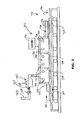
- Figure 3 is a diagram of a linear hearth furnace that may be used to carry out one or more processes described herein, and produce one or more products described herein.
- Figure 4 shows a table giving chemical compositions of one or more additives that may be used in one or more embodiments of the metallic iron nugget process described generally in Figure 1 , and/or for use in other processes that form metallic iron nuggets.
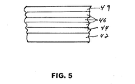
- Figure 5 is a generalized cross-section view of a hearth and the layers thereon.
- Figure 6 shows a block diagram of one exemplary embodiment of a reducible mixture provision method for use in a metallic iron nugget process as shown generally in Figure 1 , and/or for use in other processes that form metallic iron nuggets.
- Figure 7 shows a CaO-SiO 2 -Al 2 O 3 phase diagram.
- Figures 8-10 show tables for use in describing the effect of adding calcium fluoride or fluorspar to a reducible mixture in a metallic iron nugget process such as that shown generally in Figure 1 , and/or for use in other processes that form metallic iron nuggets.
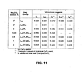
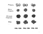
- Figures 11 , 12 and 13 show a table, an illustration, and another table, respectively, for use in showing the effect of Na 2 CO 3 and CaF 2 additives to a reducible mixture with respect to control of sulfur levels in one or more exemplary embodiments of a metallic iron nugget process such as that shown generally in Figure 1 , and/or for use in other processes that form metallic iron nuggets.
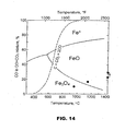
- Figure 14 is a graph showing concentrations of CO in various zones of a linear hearth furnace such as that shown in Figure 3 for use in describing one or more tests employing such a furnace.
- Figure 15 is a table showing the effect of slag composition on a reduction process for use in describing one or more tests employing a linear hearth furnace shown in Figure 3 .
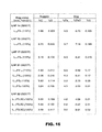
- Figure 16 is a table showing analytical results of iron nuggets and slag for use in describing one or more tests employing a linear hearth furnace shown in Figure 2D.
- Figures 17 and 18 show the effect of use of various coal addition levels on one or more exemplary embodiments of a metallic iron nugget process as shown generally in Figure 1 , and/or for use in other processes that form metallic iron nuggets.
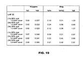
- Figure 19 is a table showing analytical results of iron nuggets and slag for use in describing one or more tests employing a linear hearth furnace as shown in Figure 3 .
- Figure 20 table showing analytical results of weight distribution of iron nuggets, micro-nuggets, +20 mesh magnetic fraction and slag for use in describing one or more tests employing a linear hearth furnace shown in Figure 3 .
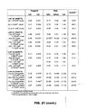
- Figure 21 is a table showing analytical results of iron nuggets and slag for use in describing one or more tests employing a linear hearth furnace shown in Figure 3 .
- Figures 22-24 show a tray with an arrangement of briquettes containing different levels of feed mixtures with the use of different levels of coarse coke overlayer therein for use in describing one or more tests employing a linear hearth furnace as shown in Figure 3 , and the resulting product from a typical test.
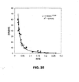
- Figure 25 shows a plot of the ratio of percent sulfur in the slag over percent sulfur in the metallic iron nuggets for tests with and without the addition of the coarse overlayer.
- Figure 26 is a table illustrating how the thickness of the hearth layer and density of the coarse cover layer affect fusion time in single, double, and triple layers of agglomerates.
- Figure 27 is a table illustrating how the thickness of the hearth layer and density of the coarse cover layer affect fusion productivity in single, double, and triple layers of agglomerates.
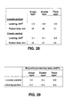
- Figure 28 is a table illustrating how the density of the agglomerates affects fusion time in single, double, and triple layers of agglomerates.
- Figure 29 is a table illustrating how the density of the agglomerates affects processing rates in single, double, and triple layers of agglomerates.
- Figure 30 is a graph illustrating fusion time as affected by the loading of loose-packed and close-packed agglomerates in single, double, and triple layers.
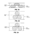
- Figure 31 is a schematic cross-sectional representation illustrating the stacking of multiple layers of closely-packed briquettes forming a stratum.
- Figure 32 is a schematic cross-sectional representation illustrating the stacking of multiple layers of loosely-packed briquettes forming a stratum.
- Figure 33 is a schematic cross-sectional representation illustrating the stacking of multiple layers of closely-packed balls forming a stratum.
- Figure 34 is a schematic cross-sectional representation illustrating the stacking of multiple layers of loosely-packed balls forming a stratum.
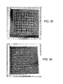
- Figure 35 shows a tray stacked with two layers of briquettes.
- Figure 36 shows the tray of Figure 34 after heating the tray with a coarse coke overlayer.
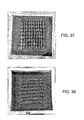
- Figure 37 shows a tray stacked with three layers of briquettes.
- Figure 38 shows the tray of Figure 37 after heating the tray with a coarse coke overlayer.
- FIG 1 shows a block diagram of one or more generalized illustrative embodiments of a metallic iron nugget process 10.
- the metallic iron nugget process 10 shown in the block diagram shall be described with further reference to a more detailed embodiment shown in Figure 3 .
- One skilled in the art will recognize that one or more of the process steps described with reference to the metallic iron nugget process 10 may be optional.
- blocks 20, and 26 are labeled as being optionally provided.
- the metallic iron nugget process 10 is an illustrative embodiment, and that the present invention is not limited to any specific process embodiments described herein, but rather as described in the accompanying claims.
- a hearth 42 is provided as shown in Figure 5 .
- the hearth 42 may be any moving hearth suitable for use with a furnace system 30 (e.g., such as that shown generally in Figure 2 ) operable for use in carrying out the metallic iron nugget process 10, or another metallic nugget processes that incorporate one or more features described herein.
- hearth 42 includes a refractory material upon which reducible material to be processed (e.g., feed material) is received.
- Hearth 42 may be a hearth suitable for use in a rotary hearth furnace, a linear hearth furnace (e.g., as shown in Figure 3 ), or any other furnace system operable for implementation for direct reduction of metallic iron nuggets.
- the refractory material may be, for example, refractory board, refractory brick, ceramic brick, or a castable refractory.
- the hearth may include a supporting substructure that carries a refractory material (e.g., a refractory lined hearth) forming hearth 42.
- the supporting substructure may be formed from one or more different materials, such as, for example, stainless steel, carbon steel, or other metals, alloys, or combinations thereof that have the required high temperature characteristics for furnace processing.
- a hearth material layer 44 is provided on hearth 42.
- the hearth material layer 44 includes at least one carbonaceous material.
- carbonaceous material refers to any carbon-containing material suitable for use as a reductant with the iron-bearing material.
- the hearth material layer 44 includes coke, char, other carbonaceous material, or mixtures thereof.
- anthracite coal low volatile bituminous coal, medium volatile bituminous coal, high volatile bituminous coal, sub-bituminous coal, coke, graphite, or other sub-bituminous char materials may be used for the hearth layer 44.
- Some low, medium, and high volatile bituminous coals may not be suitable for use as hearth layers by themselves, but may be used as make-up materials to pulverized bituminous char.
- coke materials such as coke breeze may be used.
- the carbonaceous material of the hearth layer may contain an amount of sulfur in a range from about 0.2% to about 1.5%, and more typically, in the range of 0.5% to 0.8%.
- the hearth material layer may be comprised of a mixture of finely divided coal and a material selected from the group of coke, char, and other carbonaceous material found to be beneficial to increase the efficiency of iron reduction.
- the coal particles may be a mixture of different coals such as non-coking coal, non-caking coal, sub-bituminous coal, Powder River Basin ("PRB") coal, or lignite.
- PRB Powder River Basin
- the finely divided coal may comprise up to twenty-five percent (25%) mixed with coke, char, other carbonaceous material, or mixtures thereof.
- up to fifty percent (50%) of the hearth material layer may comprise coal, or up to seventy-five percent (75%) of the hearth material layer may comprise coal, with the remaining portion coke, char, other carbonaceous material, or mixtures thereof.
- One advantage of the addition of coal to the hearth material layer is contemplated to be the volatiles in the coal that are available to be combusted and provide heat for the process.
- the volatiles can be directly burned near the location of their volatilization from the coal, or may be communicated a different location in the furnace to be burned at a more desirable location. In any case, the volatiles can be consumed to heat the reducible material efficently.
- the addition of coal may decrease the necessity for external fuel sources, while still protecting the hearth refractories.
- the hearth material layer 44 is of a thickness sufficient to prevent slag from penetrating the hearth material layer 44 and contacting refractory material of hearth 42.
- the carbonaceous material may be ground or pulverized to an extent such that it is fine enough to prevent the slag from such penetration, but typically not so fine as to create excess ash.
- contact of slag with the hearth 42 during the metallic iron nugget process 10 produces undesirable damage to the refractory material of hearth 42.
- a suitable particle size for the hearth layer is less than 4 mesh 1 1
- the mesh size of the discrete particles is measured by Tyler Mesh Size for the measurements given herein and desirably between 4 and 100 mesh, with a reasonable hearth layer thickness of about 1 ⁇ 2 inch or more, is effective protection for the hearth 42 from penetration of the slag and metallic iron during processing.
- Carbonaceous material less than 100 mesh is generally high in ash and also may result in entrained dust that is difficult to handle in commercial operations.
- multiple layers of reducible mixture 46 are provided on the underlying hearth material layer 44.
- the multiple layers of reducible mixture include at least a reducible iron-bearing material and reducing material for the production of iron metal nuggets.
- iron-bearing material includes any material capable of being formed into metallic iron nuggets via a metallic iron nugget process 10 as described herein.
- the iron-bearing material may include iron oxide material, iron ore concentrate, taconite pellets, recyclable iron-bearing material, pellet plant wastes and pellet screened fines. Further, such pellet plant wastes and pellet screened fines may include a substantial quantity of hematite.
- iron-bearing material may include magnetite concentrates, oxidized iron ores, steel plant wastes (e.g., blast furnace dust, basic oxygen furnace (BOF) dust and mill scale), red mud from bauxite processing, titanium-bearing iron sands and ilmenites, manganiferous iron ores, alumina plant wastes, or nickel-bearing oxidic iron ores. Also, less expensive iron ores high in silica may be used. Other reducible iron bearing materials may also be used for making the reducible mixture for producing metallic iron nuggets used in the processes described herein to produce metallic iron nuggets.
- nickel-bearing laterites and garnierite ores for ferronickel nuggets or titanium bearing iron oxides such as ilmenite that can be made into metallic titanium iron nuggets (while producing a titania rich slag), or iron rich oxides which contain manganese oxides can be used to produce manganese iron nuggets.
- such iron-bearing material may be ground to less than 65 mesh (i.e., -65 mesh) or less than 100 mesh (i.e., -100 mesh) in size for processing according to the disclosed processes.
- the various examples presented herein use iron-bearing material ground to 100 mesh and less unless otherwise specified.
- larger size particles of iron-bearing material may also be used.
- pellet screened fines and pellet plant wastes are generally approximately 3 mesh (about 0.25 inches) in average size.
- Such material may be used directly, or may be ground to -65 or -100 mesh to provide larger surface contact of carbonaceous reductant with the iron bearing material during processing.
- the reduction process is generally more effective to efficiently produce metallic iron nuggets with increased surface area with more finely divided material.
- the carbonaceous material for the reducible mixture may be ground to 100 mesh or less in size for processing. In another embodiment, such carbonaceous material is provided in the range of -65 mesh to -100 mesh. However, carbonaceous material in the range of -200 mesh to -8 mesh may also be used.
- coarser carbonaceous material e.g., coal
- Finer ground carbonaceous material may be more effective in the reducible mixture.
- Even larger size carbonaceous material may also be used. For example, carbonaceous material of less than about 6 to 7 mesh (e.g., about 0.13 inch to about 0.11 inch) in average size may be used.
- Such larger size material may be used directly, or may be ground to -65 or - 100 mesh for better contact and more efficiently react with the iron-bearing reducible material during processing.
- the various examples presented herein use carbonaceous material ground to -100 mesh unless otherwise specified. When other additives are also added to the reducible mixture, such additives may also ground to -100 mesh or less in size.
- Various carbonaceous materials may be used in providing the reducible mixture of reducing material and reducible iron-bearing material.
- eastern anthracite and bituminous non-caking coals may be used as the carbonaceous reductant in at least one embodiment.
- western sub-bituminous non-caking coal offers an attractive alternative, as such coals are more readily accessible with the rail transportation systems already in place, plus they are generally lower in cost and lower in sulfur levels.
- western sub-bituminous coals may be used in one or more processes as described herein.
- an alternative to the direct use of sub-bituminous coals may be to carbonize it, e.g., at 900 °C, prior to its use.
- the carbonaceous material in the reducible mixture may contain an amount of sulfur in a range from about 0.2% to about 1.5%, and more typically, in the range of 0.5% to 0.8%.
- the amount of reducing material in the mixture of reducing material and reducible iron bearing material will depend on the stoichiometric quantity necessary for complete metallization of the iron in the reducing reaction in the furnace process. As described further below, such a quantity may vary depending on the furnace used and the furnace atmosphere in which the reducing reaction takes place. In one or more embodiments, the quantity of reducing material necessary to carry out the reduction of the iron-bearing material is between about 70 percent and 90 percent of the stoichiometric quantity of reducing material theoretically necessary for carrying out the reduction to completely metallize the iron.
- Such carbonaceous material may be used at different stoichiometric levels (e.g., 70 percent, 80 percent or 90 percent) of the stoichiometric amount necessary for reduction of the iron-bearing material.
- stoichiometric levels e.g., 70 percent, 80 percent or 90 percent
- balls have a density of about 2.1
- briquettes or extrusions have a density of about 2.1. This feature of the invention is described in more detail below.
- the reducible mixture 46 may have a thickness of more than 0.25 inches (6.35 mm) and less than 2.0 inches (50.8 mm). In some embodiments, the reducible mixture 46 may have a thickness of less than 1 inch (25.4 mm) and more than 0.5 inches (12.7 mm). In other embodiments, the reducible mixture 46 may have a thickness of about 0.5 inches or less (12.7 mm or less).
- a briquette may have a dimension of 1.33 inches by 0.84 inches by 0.56 inches. Such briquettes would have a major dimension of 1.33 inches and a minor dimension of 0.56 inches. In another embodiment, a briquette may have a dimension of 1.38 inches by 0.88 inches by 0.48 inches.
- Such briquettes would have a major dimension of 1.38 inches and a minor dimension of 0.48 inches.
- the thickness of the reducible mixture is generally limited and/or dependent upon the effective heat penetration therein. Increased surface area of iron bearing material and carbonaceous material in the reducible mixture allows for improved heat transfer and reduction activity.
- additives may optionally be provided to the reducible mixture, for one or more purposes, in addition to the reducing material (e.g., coal or char) and reducible iron-bearing material (e.g., iron oxide material or iron ore).
- reducing material e.g., coal or char
- reducible iron-bearing material e.g., iron oxide material or iron ore
- additives may be provided (i) for controlling slag basicity, (ii) for binders to provide binder functionality (e.g., lime can act as a weak binder in a micro-agglomerate configuration when wetted), (iii) for controlling the slag fusion temperature, (iv) to reduce the formation of micro-nuggets, and/or (v) for further controlling the content of sulfur in resultant iron nuggets formed by the metallic iron nugget process 10.
- the table of Figure 4 shows the chemical compositions of various additives to the reducible mixture 46. That includes, for example, chemical compositions such as Al(OH) 3 , bauxite, bentonite, Ca(OH) 2 , lime hydrate, limestone, and Portland cement.
- additives may also be used such as CaF 2 , Na 2 CO 3 , fluorspar, soda ash, aluminum smelter slag, cryolite, and SiO 2 .
- One or more of such additives, separately or in combination, may provide for beneficial results when used in the metallic iron nugget process 10. These additives and their impact particularly in reducing sulfur levels in the metallic iron nuggets is explained in more detail below.
- Some of the illustrated additives contain trace amounts of Mg, as shown. Mg, in compounds such as dolomite, should be avoided and in any event is not used in quantities that will produce 5% mass or more MgO in the resulting slag.
- the reducible mixture 46 may be then formed into agglomerates such as briquettes, balls, or extrusions for use in the disclosed process of forming metallic iron nuggets. It should also be noted that different pressurization during formation of the agglomerates may result in different processing characteristics as desired for the particular embodiment of the present process.
- a layer containing coarse carbonaceous material 49 may be provided over multiple layers of agglomerates of the reducible mixture.
- the coarse carbonaceous material of the overlayer has an average particle size greater than an average particle size of the hearth layer.
- the overlayer of coarse carbonaceous material may include discrete particles having a size greater than about 4 mesh or about 6 mesh and in some embodiments, the overlayer of coarse carbonaceous material may have discrete particles with a size between about 4 mesh or 6 mesh and about 1 ⁇ 2 inch (about 12.7 mm).
- the coarse carbonaceous material may be coke, coal, char, or a combination of one or more of these.
- a reducing furnace 34 (shown in Figure 2 ) is provided to thermally directly reduce the layers of reducible mixture 46 to produce one or more metallic iron nuggets in one or more of the plurality of agglomerates.
- the reducing furnace 34 may include any suitable furnace regions or zones for providing the appropriate conditions (e.g., drying/heating, reducing, fusion and cooling zones) for processing the reducible mixture 46 of the agglomerates to form one or more metallic iron nuggets.
- a linear hearth furnace, or any other furnace capable of performing the thermal treatment (block 24 of Figure 1 ) of the reducible mixture 46 may be used.
- Slag beads on hearth material layer 44 are separated from the iron nuggets or attached thereto.
- the metallic iron nuggets and slag e.g., attached slag beads
- the discharged metallic nuggets are then separated from the slag (block 29).
- the process of formation of the metallic iron nuggets is markedly improved by the overlayer 49 of coarse carbonaceous material.
- the partitioning of the sulfur in the slag of the intermediate slag/metallic nugget product is improved by lowering the sulfur levels in the metallic iron nuggets without large amounts of MgO in the slag.
- the carbonaceous material of the coarse overlayer may contain an amount of sulfur in a range from about 0.2% to about 1.5%, and more typically, in the range of 0.5% to 0.8%.
- Metallic iron nugget processes that differ from that described with reference to Figure 1 (e.g., the ITmk3 process, the Hi-QIP process) also can be adapted to practice the process described herein and to produce the novel intermediate slag/nugget product with high sulfur partitioning into the slag.
- the same reducing material and same iron bearing materials may be used (i.e., type of composition), but the form of the reducible mixture on the hearth may be different.
- the form that the reducible mixture takes may be preformed green balls using binder, rather than briquettes or other type of agglomerates.
- the process may be used to form novel intermediate products with ratios of sulfur in slag to sulfur in nuggets of greater than 12, or 15 or 30, and novel metallic iron nuggets with less than 0.03% sulfur, and not just with the process described above with reference to Figure 1 .
- the metallic iron nugget process 10 may be carried out by a furnace system 30 as shown generally in Figure 2 .
- the furnace system 30 generally includes a charging apparatus 36 operable to provide a layer of reducible mixture 46 on at least a portion of hearth material layer 44.
- the charging apparatus may include any apparatus suitable for providing a reducible mixture 46 onto a hearth material layer 44.
- a controllable feed chute, a leveling device, and a feed direction apparatus may be used to place such reducible mixture on the hearth 42.
- Apparatus 37 can also be used to provide the coarse carbonaceous overlayer 49 over the agglomerates, which may also partially fill the areas surrounding the agglomerates.
- the furnace system 30 includes a discharge apparatus 38 used to remove the metallic nuggets and the slag formed during processing by the furnace system 30, and discharge such components (e.g., metallic iron nuggets and slag) from the system 30 after the metallic iron nuggets are cooled and solidified.
- the discharge apparatus 38 may include any number of various discharge techniques including gravity-type discharge (e.g., tilting of a tray including the nuggets and slag) or techniques using a screw discharge device or a rake discharge device.
- gravity-type discharge e.g., tilting of a tray including the nuggets and slag
- a screw discharge device or a rake discharge device e.g., a screw discharge device or a rake discharge device.
- any number of different types of discharge apparatus 38 may be suitable for providing such discharge of the nuggets (e.g., iron nugget and slag bead aggregates).
- a separation apparatus may then be used to separate the metallic iron nuggets from the slag beads. Any method of breaking and separating the iron nugget and slag bead aggregates may be used, e.g., tumbling in a drum, screening, or a hammer mill. However, any suitable separation apparatus may be used (e.g., a magnetic separation apparatus).
- One or more different reducing furnaces may be used according to the disclosed processes depending on the particular application of the disclosed processes.
- laboratory furnaces were used to perform the thermal treatment.
- scaling to mass production level can be performed and the present processes contemplate such scaling.
- various types of apparatus described herein may be used in larger scale processes, or production equipment necessary to perform such processes at a larger scale may be used.
- a linear hearth furnace such as that described in U.S. Provisional Patent Application No. 60/558,197 , entitled “Linear hearth furnace system and methods," filed 31 March 2004, published as US 2005/0229748A1 , may also be used.
- a summary of the linear hearth furnace described therein is as follows.
- One exemplary embodiment of such a linear hearth furnace is shown generally in Figure 3 and, may be, a forty-foot long walking beam iron reduction furnace 712 including three heating zones 728, 730, 731 separated by internal baffle walls 746, and also including a final cooling section 734.
- various tests were also run using this linear hearth furnace and results thereof are described with reference to the Figures.
- Zone 728 is described as an initial heating and reduction zone. This zone may operate on two natural gas-fired 450,000 BTU (113,398 Kcal) burners 738 capable of achieving temperatures of 1093°C. The burners are typically operated sub-stoichiometrically to minimize oxygen levels.
- BTU 113,398 Kcal
- Zone 730 is described as the reduction zone. This zone may operate on two natural gas-fired 450,000 BTU (113,398 Kcal) burners 738 capable to achieve 1316°C. The reduction of the feed mixture occurs in this zone 730.
- Zone 731 is described as the melting/fusion zone. This zone may operate on two natural gas-fired 1,000,000 BTU (251,995 Kcal) burners 738 capable to sustain this zone at 1426°C. The function of this zone is to complete the reduction, fusing the iron into metallic iron nodules or "nuggets". In the event that this furnace is being used to make direct reduced iron or sponge iron, the temperatures in this zone would be reduced where complete reduction would be promoted without melting or fusion.
- the walking beam 724 transports trays 715 to the opposite end 722 of the furnace where they are discharged onto a similar platform (roller ball plate) elevator 754.
- a safety mechanism has been installed to monitor the position of the hot trays at the discharge of the furnace.
- Discharge rollers drive the trays onto the platform elevator where they can be removed or re-inserted back into the furnace. The discharge rollers will not function unless trays are in position for discharge, platform elevator is in the "up" position, and the walking beams have been lowered to prevent hot trays from accidental discharge.
- Tiered conveyor rollers are located at the discharge of the furnace to remove and store sample pallets until cool.
- the exhaust gas system 747 is connected to an exhaust fan 753 with a variable flue damper controlled by the furnace PLC. Because the exhaust fan 753 is oversized for this application, a manually controlled in-line damper or pressure control 755 is used to reduce the capacity of the exhaust fan 753 to improve zone pressure control. As a safety precaution, a barometric leg into a level controlled water tank is installed between the common header and exhaust fan to absorb any sudden pressure changes. Exhaust gases are discharged from the fan 753 to a forty-foot exhaust stack 757.
- the exhaust ducts are refractory lined to the exterior walls of the furnace where they transition to high temperature stainless steel (RA602CA), fitted with water spray nozzles 749, used to cool the waste gases.
- RA602CA high temperature stainless steel
- the sample trays or pallets 715 have 30 inch square refractory lined pans with a flat bottom to be conveyed through the furnace by the walking beam mechanism 724.
- the trays framework may be made from a 303 stainless steel alloy or carbon steel. They may be lined with high temperature refractory brick or ceramic fiberboard with sidewalls to contain the feed mixture.
- furnace systems are given to further illustrate the nugget formation process 10, and has provided certain aspects in testing and the results reported herein.
- any suitable furnace system capable of carrying out one or more embodiments of a metallic iron nugget formation process described herein may be used.
- carbonaceous reducing materials are typically added to the reducible mixture in an amount greater than the theoretical stoichiometric amount required to complete reduction the iron oxides. This is done to promote carburizing of metallic iron in order to lower the melting point and the reduction temperature of the reducible mixture to metallic iron.
- the amount of carbonaceous reductant in the balls includes an amount required for reducing iron oxide plus an amount required for carburizing metallic iron and for loss associated with oxidation.
- micro-nuggets i.e., nuggets that are too large to pass through a 20 mesh screen (+20 mesh material) and less than about 1/8" (about 3 mm).
- reducing material e.g., coal
- micro-nuggets i.e., nuggets that are too large to pass through a 20 mesh screen (+20 mesh material) and less than about 1/8" (about 3 mm).
- Such micro-nugget formation we have found related to the gas turbulence and its composition in the furnace atmosphere in an area near the reducible mixture during processing.
- the reducible mixture includes a predetermined quantity of reducing material (e.g., carbonaceous reductant) between about 70 percent and about 90 percent of the stoichiometric amount necessary for complete metallization thereof.
- reducing material e.g., carbonaceous reductant
- Carbon needed for further reduction and carbonizing molten metal came from, for example, CO in the furnace atmosphere from oxidization of the carbonaceous material of the coarse carbonaceous overlying layer 49 and underlying carbonaceous hearth material layer 44.
- the sub-stoichiometric carbon levels in the reducible mixtures are believed to assist in controlling the nucleation sites and inhibiting formation of small metallic nuggets that do not consolidate in larger nuggets.
- the stoichiometric requirements in carbon for complete reduction of the iron in the metallic nuggets are satisfied from the carbon in the hearth layer and the overlayer. These sources are believed to also provide the additional carbon needed for dissolved carbon in the iron phase of the metallic iron nuggets.
- the availability of carbon from the hearth layer and overlayer for solubilization into the reduced iron lowers its melting point, and in turn reduces the processing temperature needed for metal/slag separation.
- control of the amount of reducing material in the reducible mixture based on the stoichiometric amount theoretically necessary to complete the metallization process applies not only to the methods described with reference to Figure 1 , but also to other direct reduction processes for forming metallic nuggets.
- the coarse overlayer together with the underlying hearth layer described herein reduces the formation of micronuggets formed in the reduction process.
- the reducible mixture 46 for use in the metallic iron nugget process 10 may include one or more additives in combination with the reducing material and the reducible iron-bearing material (e.g., reducible iron oxide material).
- One such method 200 for providing the reducible mixture 46 with optional additives is shown in the block diagram of Figure 6 .
- a mixture of at least reducing material of carbonaceous material such as coal, coke or charcoal and reducible iron oxide material are provided (block 202).
- calcium oxide or one or more compounds capable of producing calcium oxide upon thermal decomposition thereof may be added to the reducible mixture.
- sodium oxide or one or more compounds producing sodium oxide upon thermal decomposition may be provided (block 206), in combination with the other components of the reducible mixture.
- one or more fluxing agents may optionally may be provided for use in the reducible mixture (block 208).
- the fluxing agents that may be provided for use with the reducible mixture (block 208) may include any suitable fluxing agent.
- an agent that assists in the fusion process by lowering the fusion temperature of the reducible mixture or increases the fluidity of the reducible mixture may be included.
- the additives may be naturally part of the reducible iron bearing material used as a source for the iron oxide, and typically may be 2% of the content of the reducible iron bearing material but may range from about 1% to about 7% by weight.
- calcium fluoride (CaF 2 ) or fluorspar may be used as the fluxing agent.
- fluorspar e.g., a mineral form of CaF 2
- SiO 2 , borax, NaF, soda ash (Na 2 CO 3 ), or aluminum smelting industry slag or cryolite may be used as the fluxing agent.
- fluorspar about 0.5% to about 4% by weight of the reducible mixture may be fluorspar.
- Fluorspar for example, as well as one or more other fluxing agents, lowers the fusion temperature of the slag phase during formation of the metallic iron nuggets, and at the same time reduces the generation of micro-nuggets. Fluorspar has been found to lower not only the nugget formation temperature, but also to be uniquely effective in decreasing the amount of micro-nuggets generated. It is believed that the lower temperature slag allows for removal of slag from the reducing iron and formation of the metallic iron nuggets.
- the level of lime or one or more other compounds capable of producing calcium oxide may also be increased beyond a composition (L), as shown on the CaO-SiO 2 -Al 2 O 3 phase diagram of Figure 7 that indicates the slag compositions of (A), (L), (L 1 ), and (L 2 ).
- Composition (L) is located in the low fusion temperature trough in the CaO-SiO 2 -Al 2 O 3 phase diagram.
- the slag compositions are abbreviated by indicating the amounts of additional lime used in percent as a suffix, for example, (L 1 ) and (L 2 ) indicate lime addition of 1% and 2%, respectively, over that of Composition (L).
- the amount of chemical CaF 2 (abbreviated to CF) added in percent was also indicated as a suffix, for example, (L 0.5 CF 0.25 ), which represents that 0.25% by weight of CaF 2 was added to a feed mixture with Slag Composition of (L 0.5 ).
- fluorspar is reported to be a not particularly effective desulfurizer in steelmaking slag
- sulfur in iron nuggets was found to be lowered more effectively at Slag Compositions (L 1.5 ) and (L 2 ) than at (L 1 ). Therefore, the use of fluorspar not only lowered the operating temperature and further lowered the sulfur in iron nuggets, but also has also been found to have the unexpected benefit of minimizing the generation of micro-nuggets in the metallic iron nuggets. It is believed that the melting temperature for the slag components is lower when fluorspar is employed. An increased amount of liquid slag is thus available to interact with the sulfur and capture the sulfur within the slag. If lime is present as an additive, the slag volume is increased and the fluorspar is more effective in increasing sulfur levels in the slag and decreasing sulfur levels in the metallic iron nuggets.
- calcium oxide, and/or one or more compounds capable of producing calcium oxide upon thermal decomposition may also be used (block 204).
- lime may be used as an additive to the reducible mixture.
- Increased use of lime decreased sulfur in iron nuggets from 0.084% to 0.05%.
- Increased use of lime requires increasingly higher reduction temperatures and longer time at reduction temperature for forming fully fused metallic iron nuggets.
- a substantial amount of lime is not desirable, as higher temperatures also result in less economical production of metallic iron nuggets, and reduces yields with increased formation of micronuggets.
- further decreases in sulfur content may be accomplished by use of the coarse overlayer of carbonaceous material as explained more fully herein.
- sodium oxide, and/or one or more compounds capable of producing sodium oxide upon thermal decomposition may be used in addition to lime (block 206) to lower sulfur in the formed metallic iron nuggets.
- Soda ash, Na 2 CO 3 , NaHCO 3 , NaOH, borax, NaF and/or aluminum smelting industry slag may be used to lower sulfur in the metallic iron nuggets (e.g., used in the reducible mixture).
- the sulfur levels in the metallic nuggets by use of these additives has been found to range from 0.083% to 0.018% by weight.
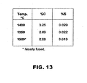
- the table of Figure 13 shows the effect of temperature on analytical results of iron nuggets formed from reducible feed mixtures.
- the reducible feed mixture included a 5.7% SiO 2 , magnetic concentrate, a Slag Composition (L 1 . 5 FS 1 SC 1 ), and medium-volatile bituminous coal at 80% of the stoichiometric requirement for metallization.
- the reducible feed mixture was heated in the tube furnace at the listed temperatures for 7 minutes in a N 2 -CO atmosphere.
- sulfur in the iron nuggets decreased markedly with decreasing temperature from 0.029% S at 1400°C to 0.013% S at 1325°C.
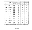
- Figure 8 shows the effect of fluorspar addition on analytical results of iron nuggets formed from feed mixtures that included a 5.7% SiO 2 magnetic concentrate, medium-volatile bituminous coal at 80% of the stoichiometric requirement for metallization and slag composition (L 1 ), (L 1 . 5 ), and (L 2 ).
- the samples in a 2-segment pattern in boats were heated at 1400 °C for 7 minutes in a N 2 -CO atmosphere.
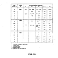
- the table of Figure 11 shows the effect of Na 2 CO 3 and CaF 2 additions on sulfur analysis of iron nuggets at different levels of lime addition, the iron nuggets formed from feed mixtures that included a 5.7% SiO 2 magnetic concentrate, medium-volatile bituminous coal at 80% of the stoichiometric requirement for metallization, and slag composition (L m CF 1 or L m FS 1 ).
- the feed mixtures were heated in the tube furnace at 1400 °C for 7 minutes in a N 2 -CO atmosphere.
- Analytical results of iron nuggets and slags of linear hearth furnace Tests 14 and 17 are given in Figure 15 , along with such results for another Test 15.
- linear hearth furnace Test 15 a tray having an arrangement of feed mixtures in domes was used.
- the feed mixture of Test 15 included medium-volatile bituminous coal at 115% and 110% of the stoichiometric amount and at Slag Compositions (L 1.5 FS 1 ), placed on a layer of -10 mesh coke. No overlayer of coarse carbonaceous material was used during these tests.
- novel metallic iron nuggets with less than 0.05% sulfur can be produced with the addition of additives to the reducible mixture.
- additives add to the expense of producing the metallic iron nuggets of the disclosed process.
- the tests were run using a 40-ft. long (12.19 m), natural gas-fired linear hearth furnace including three heating zones and a cooling section like that described with reference to Figure 3 .
- the heating schedule of feed samples in the furnace was modified to eliminate the baffle between the reduction zone (Zone 2) and the fusion or high temperature zone (Zone 3). No Mg was deliberately added beyond trace amounts or impurities found in the materials used.
- Sample trays (or pallets) as illustrated in Figure 22 were used in the tests.
- the trays were made from a 30 inch square carbon steel framework and were lined with high temperature fiber board (with sidewalls) to contain samples (i.e., the reducible mixture and products resulting after completion of reduction processing.
- the trays were conveyed through the furnace by a hydraulically driven walking beam system as described with reference to Figure 3 .
- a 1 ⁇ 2" (12.7 mm) layer of anthracite char of particle size between 6 and 100 mesh was used in each of the tests described below in this section, unless otherwise stated.
- the sample tray traveled through Zone 1 at 1800°F (982°C) for 3 minutes without stopping, then through Zone 2 at 2400°F (1316°C) by moving one stroke of 5.5" (140 mm) every 16 seconds for a total time of 5 minutes. Then, the tray was moved to the center of Zone 3 (in 55 seconds) for a total time of 10 minutes. The tray was held in Zone 3 at 2600°F (1427°C) for long enough time to visually ascertain fusion of the mounds or briquettes, and then moved into the cooling zone without stoppage. The tray was held in the cooling zone for 20 minutes and then discharged.
- Test LHF 26 in Figure 22 are dry briquettes with a coarse coke overlayer.
- two columns of dry briquettes at 80% and 110% stoichiometric amount of coal without a binder were arranged as shown in Figure 22 .
- the briquettes were provided with a coarse coke overlayer between 1/4" (6.35 mm) and 1/2" (12.7 mm) particle size at 1.0 and 0.75 lb/ft 2 (4.88 and 3.66 kg/m 2 ) in Rows (a) and (b), respectively.
- a sheet of paper was placed over the feed mixtures to prevent accidental mixing with coarse coke when the coke was distributed over the reducible feed mixture.
- the coke-overlayered feed is shown in Figure 23 .
- the tray was held at 2552°F (1400°C) for 20 minutes in Zone 3.
- Test LHF 29 was briquettes with different degrees of coarse coke overlayer at a lower temperature.
- Test LHF 26 the products formed at 1427°C (2600°F) were all fused into metallic iron nuggets.
- an identical tray of dry briquettes overlayered with coarse coke, as shown in Figure 22 was sent through the furnace according to the standardized heating schedule, but with the temperature of Zone 3 lowered to 1399°C (2550°F) and kept at that temperature for 20 minutes.
- Micro-nuggets at 80% stoichiometric amount of coal were low, 1.0 and 0.5%, for coarse coke overlayers of between 1/4" (6.35 mm) and 1/2" (12.7 mm)particle size at 1.0 and 0.75 lb/ft 2 (4.88 and 3.77 kg/m 2 ) coverage, respectively. Meanwhile, those at 110% stoichiometric amount of coal were notably higher, 5.0 and 3.5%, for coarse coke overlayers of 1.0 and 0.75 lb/ft 2 (4.88 and 3.77 kg/m 2 ) coverage, respectively. Therefore, again, as previously observed, the generation of micro-nuggets was less at 80% stoichiometric amount of coal in the reducible mixture. It is also noted that the lower coverage by coarse coke overlayer generated less micro-nuggets.
- the relationship (i.e., the ratio) of sulfur in the slag over sulfur in the metallic nuggets, (S)/[S], is plotted as a function of the percent by weight sulfur in the nuggets for the various tests that have been done.
- the filled squares ( ⁇ ) are for the LHF tests on reducible feed mixtures using 5.3% SiO 2 taconite concentrate, a Slag Composition L 1.5 FS 2 , and 80% stoichiometric Fording Standard coal.
- the open squares ( ⁇ ) are for box furnace tests on reducible feed mixture using 3.6% SiO 2 taconite concentrate, a Slag Composition L 1.5 FS 2 , and 80% stoichiometric Jim Walter coal.
- the coarse coke overlayer enabled carburizing both from the hearth layer and the coarse coke overlayer.
- the availability of carbon from the coarse overlayer is advantageous in lowering the overall processing temperature requirements, while creating the necessary reduction conditions to allow effective separation of sulfur into the slag.
- the use of a reducible feed mixture that includes a reducible mixture, on the hearth layer, that has a predetermined quantity of reducing material between about 70 percent and about 90 percent of the stoichiometric amount of reducing material and with a coarse carbonaceous material or an overlayer of turbulent gas flow disrupting material over at least a portion of the layer of the reducible mixture results in complete metallization thereof, and also reduce the potential for formation of micro-nuggets. The result was reproduced with the box and tube furnaces.
- reducing material e.g., coal
- the overlayer may be used with the overlayer to obtain almost complete metallization and formation of metallic iron nuggets from a predetermined quantity of reducible iron bearing material, the reducing material (e.g., coal) and the iron bearing material providing a reducible feed mixture for processing according to one or more embodiments described herein.
- NRI nodular reduced iron
- FIG. 26 is a table that summarizes the fusion time for the NRI in minutes as it relates to numbers of layers of agglomerates, hearth material layer thickness, and cover layer density. As shown in Figure 26 , fusion time for agglomerates increases as the number of layers of agglomerates increases, as the thickness of the hearth material layer increases, and as the density of the cover layer increases.
- Figure 27 details the productivity of NRI fusion, expressed as the ratio of the number of agglomerates in a batch and fusion time in minutes.
- productivity increased as the number of layers of agglomerates increased, as the thickness of the hearth layer decreased, and as the density of the cover layer decreased.
- productivity increased 10-20% when the cover layer decreased from 1 to 0.75 lb/ft 2 ; 15-20% when the hearth material layer thickness decreased from 1" to 1 ⁇ 2"; increased 40-50% when agglomerates increased from single to double layers; and 50-60% when agglomerates were increased from single to triple layers in processing.
- productivity increased 100% when the hearth layer thickness decreased from 1" to 1 ⁇ 2", the cover layer decreased from 1 lb/ft 2 to 0.75 lb/ft 2 , and double and triple layers of agglomerates were used in processing.
- the multiple layers of agglomerates may be positioned on a hearth material layer of at least carbonaceous material and a coarse overlayer of carbonaceous material may be placed over the layers of agglomerates.
- a stratum of agglomerates may or may not comprise discrete layers, or may partially comprise one or more discrete layers of agglomerates. If, for example, a plurality of agglomerates were placed on a hearth material layer and some stacking of agglomerates occurred during placement of the agglomerates, the stratum of agglomerates may not fully comprise discrete layers. Nevertheless, such a stratum of agglomerates may effectively increase the productivity of NRI production.
- the actual height of two closely-packed layers may be approximately 1.8 to 1.9 times the height of a single layer because of partial nesting of the top layer of agglomerates in the interstitial space of the bottom layer.
- the height of two layers may be 1.5 to 1.8 times the height of a single layer, and more typically about 1.7 to 1.8 times the height of a single layer.
- a stratum of agglomerates may be utilized where the stratum height is at least 1.7 times the height of a single layer of agglomerates. More particularly, some agglomerates like briquettes or extrusions include a larger major dimension or length and a smaller minor dimension or height. With balls, on the other hand, the major dimension and minor dimension would be the same.
- An exemplary embodiment of a briquette may have a dimension of 1.33 inches by 0.84 inches by 0.56 inches. Such briquette would have a major dimension of 1.33 inches and a minor dimension of 0.56 inches. It is therefore contemplated that an embodiment of the disclosed method may comprise a stratum of agglomerates where the height of the stratum comprises at least 1.7 times the minor dimension of the individual agglomerates.
- FIG. 31-34 illustrate schematically cross-sections of agglomerates and balls closely-packed and loosely-packed.
- the tests were also performed on briquettes as the agglomerate, with a hearth material layer and a coarse overlayer or cover layer.
- Figure 28 as the agglomerates became more densely-packed in a given layer, gross fusion time increased but productivity increased.
- the number of layers increased gross fusion time increased but productivity increased.
- processing rates of agglomerates expressed as the ratio of loading and fusion time in lb/ft 2 /hr, increased as the number of layers increased and as the loading density or density ("loading density") of the agglomerates increased.
- the processing rates were highest (8.4 lb/ft 2 /hr) in closely packed agglomerates in three layers-233% higher than loosely-packed agglomerates in one layer.
- the agglomerates may be positioned in one or more layers where the loading density of the layer(s) is at least 2.5 lb/ft 2 /layer, at least 2.8 lb/ft 2 /layer, or 3 lb/ft 2 /layer or greater.
Applications Claiming Priority (2)
| Application Number | Priority Date | Filing Date | Title |
|---|---|---|---|
| US2486108P | 2008-01-30 | 2008-01-30 | |
| EP09712738.5A EP2247759B1 (fr) | 2008-01-30 | 2009-01-30 | Procédé et système pour produire des pépites de fer métallique |
Related Parent Applications (2)
| Application Number | Title | Priority Date | Filing Date |
|---|---|---|---|
| EP09712738.5A Division-Into EP2247759B1 (fr) | 2008-01-30 | 2009-01-30 | Procédé et système pour produire des pépites de fer métallique |
| EP09712738.5 Division | 2009-01-30 |
Publications (1)
| Publication Number | Publication Date |
|---|---|
| EP2325341A1 true EP2325341A1 (fr) | 2011-05-25 |
Family
ID=40986123
Family Applications (2)
| Application Number | Title | Priority Date | Filing Date |
|---|---|---|---|
| EP10013645A Withdrawn EP2325341A1 (fr) | 2008-01-30 | 2009-01-30 | Procédés et système pour produire des pépites d'ion métalliques |
| EP09712738.5A Active EP2247759B1 (fr) | 2008-01-30 | 2009-01-30 | Procédé et système pour produire des pépites de fer métallique |
Family Applications After (1)
| Application Number | Title | Priority Date | Filing Date |
|---|---|---|---|
| EP09712738.5A Active EP2247759B1 (fr) | 2008-01-30 | 2009-01-30 | Procédé et système pour produire des pépites de fer métallique |
Country Status (7)
| Country | Link |
|---|---|
| US (1) | US8333823B2 (fr) |
| EP (2) | EP2325341A1 (fr) |
| AU (1) | AU2009215703B2 (fr) |
| CA (1) | CA2713442A1 (fr) |
| ES (1) | ES2539977T3 (fr) |
| PL (1) | PL2247759T3 (fr) |
| WO (1) | WO2009105320A2 (fr) |
Cited By (3)
| Publication number | Priority date | Publication date | Assignee | Title |
|---|---|---|---|---|
| US10364480B2 (en) | 2014-10-06 | 2019-07-30 | Sumitomo Metal Mining Co., Ltd. | Method for smelting nickel oxide ore |
| EP3447157A4 (fr) * | 2016-04-22 | 2020-03-18 | Sumitomo Metal Mining Co., Ltd. | Procédé de fusion de minerai d'oxyde |
| US11608543B2 (en) | 2016-04-27 | 2023-03-21 | Sumitomo Metal Mining Co., Ltd. | Oxide ore smelting method |
Families Citing this family (5)
| Publication number | Priority date | Publication date | Assignee | Title |
|---|---|---|---|---|
| EP2325341A1 (fr) | 2008-01-30 | 2011-05-25 | Nu-Iron Technology, Inc | Procédés et système pour produire des pépites d'ion métalliques |
| US8690986B2 (en) * | 2010-09-03 | 2014-04-08 | Forest Vue Research, Llc | Method for simultaneously producing iron, coke, and power |
| RU2637850C1 (ru) * | 2016-11-14 | 2017-12-07 | Общество С Ограниченной Ответственностью "Промышленные Инновационные Технологии Национальной Коксохимической Ассоциации" (Ооо "Проминтех Нка") | Шихта для получения железорудных окатышей (варианты) |
| CN107354257A (zh) * | 2017-07-10 | 2017-11-17 | 中冶南方工程技术有限公司 | 一种金属铁的生产方法 |
| KR20230159705A (ko) * | 2021-03-23 | 2023-11-21 | 카본텍 에너지 코퍼레이션 | 철 괴 제조 방법 및 시스템 |
Citations (7)
| Publication number | Priority date | Publication date | Assignee | Title |
|---|---|---|---|---|
| EP0947586A1 (fr) * | 1994-12-16 | 1999-10-06 | Midrex Direct Reduction Corporation | Procédé et appareil pour la réduction rapide de minerais de fer dans un four à sole rotative |
| WO2000056941A1 (fr) * | 1999-03-19 | 2000-09-28 | Midrex International B.V. Rotterdam, Zurich Branch | Traitement d'agglomerats d'oxyde de fer avant leur introduction dans un four |
| US6126718A (en) | 1999-02-03 | 2000-10-03 | Kawasaki Steel Corporation | Method of producing a reduced metal, and traveling hearth furnace for producing same |
| JP2002129218A (ja) * | 2000-10-27 | 2002-05-09 | Nippon Steel Corp | 回転床炉による還元鉄製造方法 |
| US20050229748A1 (en) | 2004-03-31 | 2005-10-20 | Regents Of The University Of Minnesota | Linear hearth furnace system and methods regarding same |
| EP1605067A1 (fr) | 2003-03-20 | 2005-12-14 | Kabushiki Kaisha Kobe Seiko Sho (Kobe Steel, Ltd.) | Procede de production de metal ferreux particulaire |
| EP1808498A1 (fr) * | 2004-10-29 | 2007-07-18 | Kabushiki Kaisha Kobe Seiko Sho | Procédé servant à produire du fer fondu et appareil pour cela |
Family Cites Families (8)
| Publication number | Priority date | Publication date | Assignee | Title |
|---|---|---|---|---|
| JP3451901B2 (ja) * | 1997-09-30 | 2003-09-29 | Jfeスチール株式会社 | 移動型炉床炉の操業方法 |
| EP1770175A1 (fr) * | 1997-09-30 | 2007-04-04 | JFE Steel Corporation | Four à sole rotative pour la réduction des oxides |
| US6413295B2 (en) * | 1998-11-12 | 2002-07-02 | Midrex International B.V. Rotterdam, Zurich Branch | Iron production method of operation in a rotary hearth furnace and improved furnace apparatus |
| JP4757982B2 (ja) * | 2000-06-28 | 2011-08-24 | 株式会社神戸製鋼所 | 粒状金属鉄の歩留まり向上方法 |
| US6648942B2 (en) * | 2001-01-26 | 2003-11-18 | Midrex International B.V. Rotterdam, Zurich Branch | Method of direct iron-making / steel-making via gas or coal-based direct reduction and apparatus |
| CA2590259C (fr) * | 2004-12-07 | 2016-02-16 | Nu-Iron Technology, Llc | Procede et systeme permettant de produire des pepites de fer metallique |
| US8021460B2 (en) * | 2006-07-26 | 2011-09-20 | Nu-Iron Technology, Llc | System and method for producing metallic iron nodules |
| EP2325341A1 (fr) | 2008-01-30 | 2011-05-25 | Nu-Iron Technology, Inc | Procédés et système pour produire des pépites d'ion métalliques |
-
2009
- 2009-01-30 EP EP10013645A patent/EP2325341A1/fr not_active Withdrawn
- 2009-01-30 PL PL09712738T patent/PL2247759T3/pl unknown
- 2009-01-30 AU AU2009215703A patent/AU2009215703B2/en not_active Ceased
- 2009-01-30 ES ES09712738.5T patent/ES2539977T3/es active Active
- 2009-01-30 WO PCT/US2009/032519 patent/WO2009105320A2/fr active Application Filing
- 2009-01-30 CA CA2713442A patent/CA2713442A1/fr not_active Abandoned
- 2009-01-30 EP EP09712738.5A patent/EP2247759B1/fr active Active
-
2010
- 2010-07-30 US US12/847,591 patent/US8333823B2/en active Active
Patent Citations (7)
| Publication number | Priority date | Publication date | Assignee | Title |
|---|---|---|---|---|
| EP0947586A1 (fr) * | 1994-12-16 | 1999-10-06 | Midrex Direct Reduction Corporation | Procédé et appareil pour la réduction rapide de minerais de fer dans un four à sole rotative |
| US6126718A (en) | 1999-02-03 | 2000-10-03 | Kawasaki Steel Corporation | Method of producing a reduced metal, and traveling hearth furnace for producing same |
| WO2000056941A1 (fr) * | 1999-03-19 | 2000-09-28 | Midrex International B.V. Rotterdam, Zurich Branch | Traitement d'agglomerats d'oxyde de fer avant leur introduction dans un four |
| JP2002129218A (ja) * | 2000-10-27 | 2002-05-09 | Nippon Steel Corp | 回転床炉による還元鉄製造方法 |
| EP1605067A1 (fr) | 2003-03-20 | 2005-12-14 | Kabushiki Kaisha Kobe Seiko Sho (Kobe Steel, Ltd.) | Procede de production de metal ferreux particulaire |
| US20050229748A1 (en) | 2004-03-31 | 2005-10-20 | Regents Of The University Of Minnesota | Linear hearth furnace system and methods regarding same |
| EP1808498A1 (fr) * | 2004-10-29 | 2007-07-18 | Kabushiki Kaisha Kobe Seiko Sho | Procédé servant à produire du fer fondu et appareil pour cela |
Cited By (5)
| Publication number | Priority date | Publication date | Assignee | Title |
|---|---|---|---|---|
| US10364480B2 (en) | 2014-10-06 | 2019-07-30 | Sumitomo Metal Mining Co., Ltd. | Method for smelting nickel oxide ore |
| EP3447157A4 (fr) * | 2016-04-22 | 2020-03-18 | Sumitomo Metal Mining Co., Ltd. | Procédé de fusion de minerai d'oxyde |
| EP3778938A1 (fr) * | 2016-04-22 | 2021-02-17 | Sumitomo Metal Mining Co., Ltd. | Procédé de fusion de minerai d'oxyde |
| US11479832B2 (en) | 2016-04-22 | 2022-10-25 | Sumitomo Metal Mining Co., Ltd. | Method for smelting oxide ore |
| US11608543B2 (en) | 2016-04-27 | 2023-03-21 | Sumitomo Metal Mining Co., Ltd. | Oxide ore smelting method |
Also Published As
| Publication number | Publication date |
|---|---|
| US8333823B2 (en) | 2012-12-18 |
| ES2539977T3 (es) | 2015-07-07 |
| US20110100162A1 (en) | 2011-05-05 |
| EP2247759A4 (fr) | 2012-03-14 |
| WO2009105320A3 (fr) | 2009-10-22 |
| EP2247759B1 (fr) | 2015-03-25 |
| PL2247759T3 (pl) | 2015-08-31 |
| AU2009215703A1 (en) | 2009-08-27 |
| WO2009105320A2 (fr) | 2009-08-27 |
| EP2247759A2 (fr) | 2010-11-10 |
| AU2009215703B2 (en) | 2014-07-17 |
| CA2713442A1 (fr) | 2009-08-27 |
Similar Documents
| Publication | Publication Date | Title |
|---|---|---|
| AU2005312999B2 (en) | Method and system for producing metallic iron nuggets | |
| US8470068B2 (en) | Method and system for producing metallic iron nuggets | |
| US8333823B2 (en) | Method and system for producing metallic iron nuggets | |
| AU2010206718B2 (en) | Production of iron from metallurgical waste | |
| CA2831461C (fr) | Utilisation d'une distribution bimodale de carbone dans des briquettes utilisees en vue de la production de nodules metalliques de fer | |
| US20120285295A1 (en) | Method for producing metallic iron nuggets | |
| AU2007279272B2 (en) | Method and system for producing metallic iron nuggets |
Legal Events
| Date | Code | Title | Description |
|---|---|---|---|
| PUAI | Public reference made under article 153(3) epc to a published international application that has entered the european phase |
Free format text: ORIGINAL CODE: 0009012 |
|
| AC | Divisional application: reference to earlier application |
Ref document number: 2247759 Country of ref document: EP Kind code of ref document: P |
|
| AK | Designated contracting states |
Kind code of ref document: A1 Designated state(s): AT BE BG CH CY CZ DE DK EE ES FI FR GB GR HR HU IE IS IT LI LT LU LV MC MK MT NL NO PL PT RO SE SI SK TR |
|
| AX | Request for extension of the european patent |
Extension state: AL BA RS |
|
| RTI1 | Title (correction) |
Free format text: METHODS AND SYSTEM FOR PRODUCING METALLIC IRON NUGGETS |
|
| 17P | Request for examination filed |
Effective date: 20111125 |
|
| 17Q | First examination report despatched |
Effective date: 20120209 |
|
| GRAP | Despatch of communication of intention to grant a patent |
Free format text: ORIGINAL CODE: EPIDOSNIGR1 |
|
| RIC1 | Information provided on ipc code assigned before grant |
Ipc: C21B 13/00 20060101ALI20140604BHEP Ipc: C22B 5/10 20060101ALI20140604BHEP Ipc: C22B 1/24 20060101ALI20140604BHEP Ipc: C21B 13/10 20060101ALI20140604BHEP Ipc: C22B 1/16 20060101ALI20140604BHEP Ipc: C22B 1/14 20060101AFI20140604BHEP |
|
| INTG | Intention to grant announced |
Effective date: 20140707 |
|
| STAA | Information on the status of an ep patent application or granted ep patent |
Free format text: STATUS: THE APPLICATION IS DEEMED TO BE WITHDRAWN |
|
| 18D | Application deemed to be withdrawn |
Effective date: 20141118 |