EP2325041A1 - Seat frame and vehicle seat - Google Patents
Seat frame and vehicle seat Download PDFInfo
- Publication number
- EP2325041A1 EP2325041A1 EP09810043A EP09810043A EP2325041A1 EP 2325041 A1 EP2325041 A1 EP 2325041A1 EP 09810043 A EP09810043 A EP 09810043A EP 09810043 A EP09810043 A EP 09810043A EP 2325041 A1 EP2325041 A1 EP 2325041A1
- Authority
- EP
- European Patent Office
- Prior art keywords
- absorbing member
- energy absorbing
- seat
- frame
- seat back
- Prior art date
- Legal status (The legal status is an assumption and is not a legal conclusion. Google has not performed a legal analysis and makes no representation as to the accuracy of the status listed.)
- Granted
Links
Images

Classifications
-
- B—PERFORMING OPERATIONS; TRANSPORTING
- B60—VEHICLES IN GENERAL
- B60N—SEATS SPECIALLY ADAPTED FOR VEHICLES; VEHICLE PASSENGER ACCOMMODATION NOT OTHERWISE PROVIDED FOR
- B60N2/00—Seats specially adapted for vehicles; Arrangement or mounting of seats in vehicles
- B60N2/24—Seats specially adapted for vehicles; Arrangement or mounting of seats in vehicles for particular purposes or particular vehicles
- B60N2/42—Seats specially adapted for vehicles; Arrangement or mounting of seats in vehicles for particular purposes or particular vehicles the seat constructed to protect the occupant from the effect of abnormal g-forces, e.g. crash or safety seats
- B60N2/4207—Seats specially adapted for vehicles; Arrangement or mounting of seats in vehicles for particular purposes or particular vehicles the seat constructed to protect the occupant from the effect of abnormal g-forces, e.g. crash or safety seats characterised by the direction of the g-forces
- B60N2/4214—Seats specially adapted for vehicles; Arrangement or mounting of seats in vehicles for particular purposes or particular vehicles the seat constructed to protect the occupant from the effect of abnormal g-forces, e.g. crash or safety seats characterised by the direction of the g-forces longitudinal
- B60N2/4228—Seats specially adapted for vehicles; Arrangement or mounting of seats in vehicles for particular purposes or particular vehicles the seat constructed to protect the occupant from the effect of abnormal g-forces, e.g. crash or safety seats characterised by the direction of the g-forces longitudinal due to impact coming from the rear
-
- B—PERFORMING OPERATIONS; TRANSPORTING
- B60—VEHICLES IN GENERAL
- B60N—SEATS SPECIALLY ADAPTED FOR VEHICLES; VEHICLE PASSENGER ACCOMMODATION NOT OTHERWISE PROVIDED FOR
- B60N2/00—Seats specially adapted for vehicles; Arrangement or mounting of seats in vehicles
- B60N2/24—Seats specially adapted for vehicles; Arrangement or mounting of seats in vehicles for particular purposes or particular vehicles
- B60N2/42—Seats specially adapted for vehicles; Arrangement or mounting of seats in vehicles for particular purposes or particular vehicles the seat constructed to protect the occupant from the effect of abnormal g-forces, e.g. crash or safety seats
- B60N2/427—Seats or parts thereof displaced during a crash
- B60N2/42709—Seats or parts thereof displaced during a crash involving residual deformation or fracture of the structure
-
- B—PERFORMING OPERATIONS; TRANSPORTING
- B60—VEHICLES IN GENERAL
- B60N—SEATS SPECIALLY ADAPTED FOR VEHICLES; VEHICLE PASSENGER ACCOMMODATION NOT OTHERWISE PROVIDED FOR
- B60N2/00—Seats specially adapted for vehicles; Arrangement or mounting of seats in vehicles
- B60N2/68—Seat frames
Definitions
- the present invention relates to a seat frame and a vehicle seat, particularly to a seat frame for reducing a load inputted to a reclining mechanism at the time of rear surface collision, and a vehicle seat.
- a notch 100 is formed in a lower side part of a seat back frame 111 in a seat frame for a vehicle seat of a motor vehicle or the like.
- a seat back (the seat back frame 111) can fall downward from a part where this notch 100 is formed.
- the excessive load above a limit inputted to a reclining mechanism 120 is prevented (for example, refer to Patent Documents 1 and 2).
- the present invention is to provide a seat frame applicable to various vehicle types, the seat frame capable of reducing an input load to a reclining mechanism at the time of rear surface collision, and a vehicle seat.
- a seat frame including a seat back frame attached to a seating frame via a reclining mechanism, the seat back frame including a pair of side frames arranged so as to be spaced from each other at least in the left and right direction and to extend in the upper and lower direction, a lower frame for coupling a pair of the side frames in the vicinity of the reclining mechanism, and an energy absorbing member attached on the front side of the lower frame, wherein the energy absorbing member is plastically deformable by pressing from the backrest surface side.
- the lower frame includes a pair of side portions respectively fixed to a pair of the side frames, and a coupling portion for coupling a pair of the side portions
- the energy absorbing member has a plastically-deformable deformation portion arranged on the front side of the coupling portion, a fixed end formed so as to be continuous to one side of the deformation portion and fixed only to the coupling portion, and a free end formed on the opposite side of the fixed end relative to the deformation portion.
- the fixed end formed so as to be continuous to the one side of the deformation portion is fixed only to the coupling portion, and an end formed on the opposite side of the fixed end relative to the deformation portion serves as the free end.
- the deformation direction of the energy absorbing member is limited to one direction, so that variation of deformation behavior is eliminated and a desired deformation characteristic can be obtained. Therefore, a planned effect can be obtained upon the rear surface collision in various situations. That is, even at the rear surface collision generated in various situations, the energy absorbing member is surely plastically deformed, so that the load inputted to the reclining mechanism can be reduced.
- the free end of the energy absorbing member is arranged so as to extend on the opposite side of the fixed end more than an end of the coupling portion on the opposite side of the side where the fixed end is fixed.
- the free end of the energy absorbing member is arranged so as to extend on the opposite side of the fixed end more than the end of the coupling portion on the opposite side of the side where the fixed end is fixed.
- the free end of the energy absorbing member is turned up.
- damage to a cushion material or a skin material arranged on the back surface side of the seat back can be prevented at the time of the deformation of the energy absorbing member.
- the energy absorbing member is formed by a metal plate, and energy to be absorbed is variable depending on a shape, thickness, and a material of the energy absorbing member.
- the energy absorbing member having a different energy absorbing characteristic can be arranged depending on size of a vehicle or the like.
- the energy absorbing member is plastically deformed at the time of the rear surface collision, the shock energy imposed onto the seat back is absorbed, so that the load inputted to the reclining mechanism can be reduced.
- the energy absorbing member having the desired deformation characteristic can be obtained.
- the energy absorbing member is surely plastically deformed, so that the load inputted to the reclining mechanism can be reduced.
- the seat frame according to claim 3 even in the case where the deformation amount of the energy absorbing member is large, the shock energy can be absorbed.
- the seat frame according to claim 4 at the time of the deformation of the energy absorbing member, the damage to the cushion material or the skin material arranged on the back surface side of the seat back can be prevented.
- the energy absorbing member suitable for each type of the vehicle can be arranged, and the versatility of the seat frame is improved.
- the vehicle seat of claim 6 the vehicle seat provided with characteristics of claims 1 to 5 can be provided.
- Figs. 1 to 4 show an embodiment of the present invention.
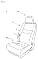
- Fig. 1 is a schematic perspective view of a vehicle seat
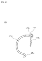
- Fig. 2 is a schematic perspective view of a seat frame
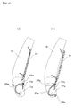
- Fig. 3 is a center sectional view (by the line I-I) of a lower frame and an energy absorbing member
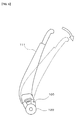
- Fig. 4 is a concept illustrative view showing a state of the energy absorbing member before and after rear surface collision.
- a vehicle seat S is provided with a seat back S1, a seat cushion S2, and a headrest HR attached to an upper part of the seat back S1.
- the seat back S1 and the seat cushion S2 of the present embodiment are formed by respectively attaching cushion materials 4 to a seat back frame 11 and a seating frame 12 (refer to Fig. 2 ) and covering outer peripheries of the cushion materials 4 with skin materials 5.
- the headrest HR is arbitrarily formed but provided with at least a head support portion supporting a head part of a passenger, and a pillar for equipping the head support portion on the side of the seat back S1.
- the backrest surface side of the seat back S1 indicates the front side, and the side of the seat back S1 where the headrest HR is attached indicates the upper side.
- the seat frame F is formed by mainly including the seat back frame 11 and the seating frame 12 described above, and a headrest frame (not shown).
- the seat back frame 11 is covered with the cushion material 4 (not shown) or the like so as to support the back of the passenger from the rear side, and in the present embodiment, formed into a substantially rectangular frame body.
- a lower end of the seat back frame 11 is coupled to the seating frame 12 via a reclining mechanism 20 so that reclining is adjustable.
- the seat back frame 11 is formed by mainly including side frames 15, 15 arranged on the side surface sides in the left and right direction, an upper frame 16 for coupling upper ends of the side frames 15, 15, and a lower frame 17 for coupling lower ends.
- the side frames 15 are a pair of extending members forming side surfaces of the seat back frame 11, arranged so as to be spaced from each other in the left and right direction and to have a predetermined length in the upper and lower direction. By respectively bending inward front ends and rear ends of main bodies of the flat plate-like side frames 15, 15, required strength is ensured.
- the upper frame 16 is a substantially U shape member. Side surface portions 16a, 16a of the upper frame 16 are arranged so as to be partially overlapped with upper parts of the side frames 15, 15, and integrally fixed and jointed to the side frames 15, 15 in the overlapped parts.
- the headrest frame (not shown) is arranged in the upper part of the seat back frame 11.
- a pillar (not shown) of the headrest frame is attached to pillar support portions 18, 18 provided in the upper frame 16.
- a pressure receiving member 21 supporting the cushion material 4 from the rear side is arranged between a pair of the side frames 15, 15.
- the lower frame 17 is a member formed by left and right side portions 17a, 17a which are fixed to the side frames 15, 15, and a coupling portion 17b for coupling the left and right side portions 17a, 17a.
- the side portions 17a, 17a are arranged so as to be partially overlapped with lower parts of the side frames 15, 15, and integrally fixed and jointed to the side frames 15, 15 in the overlapped parts.
- An energy absorbing member 25 described below is fixed to the coupling portion 17b for integrally coupling the left and right side portions 17a, 17a.
- the side portions 17a, 17a of the lower frame 17 are coupled to the seating frame 12 via the reclining mechanism 20.
- Fig. 3 is the center sectional view (by the line I-I) of the lower frame 17 and the energy absorbing member 25.
- the energy absorbing member 25 of the present embodiment is formed so as to have a substantially C shape section by curving a substantially rectangular plate-like member in the upper and lower direction, fixed to the coupling portion 17b of the lower frame 17, and arranged at a position sandwiched between the left and right side portions 17a, 17a.
- This energy absorbing member 25 is formed by a deformation portion 25a extending on the front side of the coupling portion 17b, a fixed end 25b formed on the upper part side of the deformed portion 25a, and a free end 25c formed on the opposite side of the fixed end 25b relative to the deformation portion 25a, that is, on the lower part side of the deformation portion 25a in the present embodiment.
- the energy absorbing member 25 is arranged. That is, the free end 25c on the lower part side of the energy absorbing member 25 is not fixed, and formed as a free end capable of moving downward or rearward in accordance with deformation of the deformation portion 25a by pressing from the backrest surface side.
- the free end 25c is arranged so as to extend on the opposite side of the fixed end 25b more than an end of the coupling portion 17b of the lower frame 17 on the opposite side of the side where the fixed end 25b is fixed.
- the free end 25c is arranged so as to extend on the lower side of the lower end of the coupling portion 17b.
- the lower part side of the energy absorbing member 25 may be fixed to the coupling portion 17b as the fixed end 25b, and the upper part side may be movable as the free end 25c at the time of the deformation.
- a front end of the free end 25c is turned up toward the front side, and the turned-up part is formed into a round shape. With such a shape, even when the energy absorbing member 25 is deformed by pressing from the backrest surface side, moved rearward, and brought into contact with the cushion material 4 or the skin material 5 arranged on the back surface side of the seat back S1, the cushion material 4 or the skin material 5 is not damaged.
- the energy absorbing member 25 is welded and jointed so that the fixed end 25b is continuous along the longitudinal direction of the coupling portion 17b of the lower frame 17, and a welding portion 19 is formed in the joint part. Size of the energy absorbing member 25 in the left and right direction is adjusted in a manner that left and right ends can be arranged distant from both of the side portions 17a, 17a of the lower frame 17. It should be noted that a method for fixing the fixed end 25b to the coupling portion 17b of the lower frame 17 may be rivet jointing, bolt fastening, or spot welding in addition to welding. The fixed end 25b may be caulked and fixed to the coupling portion 17b.
- the energy absorbing member 25 is desirably at a position where a lumbar part of the passenger is arranged on the backrest surface side of the deformation portion 25a. With such a positional relation, the lumbar part of the passenger moved rearward due to inertia at the time of the rear surface collision can press the energy absorbing member 25 through the cushion material 4 so as to deform the deformation portion 25a. Since shock to the lumbar part of the passenger positioned at height close to the reclining mechanism 20 can be absorbed by the deformation of the energy absorbing member 25 (the deformation portion 25a), the shock energy which is not absorbed by depressing a back part into a backrest surface can be absorbed. That is, together with a shock load inputted to the reclining mechanism 20, a shock load transmitted to the lumbar part of the passenger can be reduced.
- the energy absorbing member 25 is attached to be slightly distant from both of the inner sides of the side portions 17a, 17a of the lower frame 17.
- the deformation direction of the energy absorbing member 25 can be limited to one direction at any position. That is, by simplifying deformation behavior of the energy absorbing member 25, reproducibility of the plastic deformation is improved, so that variation is eliminated and a desired deformation characteristic can be obtained. Therefore, even in the case where a position displaced from the center of the energy absorbing member 25 is pressed by the lumbar part of the passenger, the change in the stress required for the plastic deformation is small.
- the energy absorbing member 25 can with certainty be deformed and a planned effect can be obtained. It should be noted that, since a fixing position of the energy absorbing member 25 is limited, an effect for improving an assembling property is also obtained.
- the energy absorbing member 25 arranged slightly distant from the inner sides of the left and right side portions 17a, 17a.
- the left and right side portions 17a, 17a are abutted with side ends of the energy absorbing member 25. Since the energy absorbing member 25 has a substantially C shape section, strength in the left and right direction is higher than that in the front and rear direction structurally. Therefore, deformation resistance is large against the stress imposed in the left and right direction at the time of the side surface collision or the like, so that deformation of the seat frame F can be prevented.
- the energy absorbing member 25 can be formed by a plastically-deformable metal or resin plate body, and in particular, desirably formed by a material having a high plastic deformability such as soft iron and aluminum alloy.
- a material having a high plastic deformability such as soft iron and aluminum alloy.
- energy to be absorbed can be adjusted. For example, when strength is increased by increasing the thickness of the energy absorbing member 25 or changing the material into a material having a high yield strength, larger energy can be absorbed. That is, by obtaining the desired deformation characteristic, the energy absorbing member 25 having an optimal energy absorbing characteristic can be manufactured, so that the seat frame F suitable for each type of a vehicle can be provided.
- the energy absorbing member can be deformed stepwise in accordance with the input load. For example, at the time of the rear surface collision, by forming several small holes or slits in parts where the load is inputted by the lumbar part of the passenger at an initial stage so that the energy absorbing member is easily deformed, the load imposed onto the reclining mechanism 20 via the seat back S1 at the initial stage of the rear surface collision can be reduced, and the shock load which the lumbar part of the passenger receives can also be reduced.
- Fig. 4 is an illustrative view showing a state of the energy absorbing member 25 at the time of the rear surface collision.
- Fig. 4 (a) shows the state before the collision
- Fig. 4(b) shows the state after the collision.
- the passenger receives the shock from the rear side and is moved rearward due to the inertia
- the back part of the passenger is depressed on the backrest surface side of the seat back S1 while pressing the pressure receiving member 21 rearward.
- the lumbar part of the passenger presses the energy absorbing member 25 rearward through the cushion material 4 (not shown) so as to plastically deform the energy absorbing member.
- the deformation portion 25a of the energy absorbing member 25 when the load in accordance with rearward movement of the passenger is imposed onto the deformation portion 25a of the energy absorbing member 25, the deformation portion 25a is plastically deformed downward or rearward in accordance with the imposed load.
- the free end 25c is moved rearward and sometimes brought into contact with the cushion material 4 or the skin material 5 arranged on the back surface side of the seat back S1.
- the free end since the free end is turned up into a round shape, the cushion material 4 or the skin material 5 is not damaged.
- this energy absorbing member 25 Due to the plastic deformation of this energy absorbing member 25, the shock load at the time of the rear surface collision is absorbed, so that the load imposed onto the seat back S1 can be reduced. In such a way, the shock load inputted to the reclining mechanism 20 is reduced, and the load above a limit imposed onto the reclining mechanism 20 is prevented. At the same time, the shock load applied onto the lumbar part of the passenger can also be reduced.
- the free end 25c of the energy absorbing member 25 is arranged so as to expand on the lower side of the lower end of the coupling portion 17b.
- the shock load applied onto the lumbar part of the passenger can also be reduced.
- the seat back S1 is not inclined rearward unlike a conventional mechanism using a notch 100, a chest part of the passenger can be more deeply depressed into the seat back S1.
- shear force imposed onto a cervical part can be furthermore reduced.
- the energy absorbing member 25 fixed to the coupling portion 17b of the lower frame 17 absorbs the energy at the time of the rear surface collision.
- the seat frame can be applied to various vehicle types.
- the seat frame F capable of reducing the input load to the reclining mechanism 20 and the vehicle seat S can be provided at low cost.
- the seat back S1 of a front seat of a motor vehicle is described in the present embodiment as a specific example, the present invention is not limited to this. The same configuration can also be applied to a seat back of a rear seat as a matter of course.
Landscapes
- Engineering & Computer Science (AREA)
- Aviation & Aerospace Engineering (AREA)
- Transportation (AREA)
- Mechanical Engineering (AREA)
- Seats For Vehicles (AREA)
- Chair Legs, Seat Parts, And Backrests (AREA)
Abstract
Description
- The present invention relates to a seat frame and a vehicle seat, particularly to a seat frame for reducing a load inputted to a reclining mechanism at the time of rear surface collision, and a vehicle seat.
- Conventionally, when a motor vehicle is collided at a rear part thereof or collides when backing up, so called at the time of rear surface collision, a seated passenger is sometimes radically moved rearward due to inertia and pushed onto a backrest surface of a seat back. Accordingly, there is a fear that an excessive load is inputted to a reclining mechanism for adjusting a reclining angle of the seat back.
- In order to prevent such an excessive load inputted to the reclining mechanism, as shown in
Fig. 5 , anotch 100 is formed in a lower side part of aseat back frame 111 in a seat frame for a vehicle seat of a motor vehicle or the like. At the time of the rear surface collision, a seat back (the seat back frame 111) can fall downward from a part where thisnotch 100 is formed. Thus, the excessive load above a limit inputted to a recliningmechanism 120 is prevented (for example, refer toPatent Documents 1 and 2). -
- Patent Document 1: Japanese Patent Application Publication No.
2003-335162 - Patent Document 2: Japanese Patent Application Publication No.
2006-347436 - In the techniques disclosed in
Patent Documents 1 and 2, since the entire seat back falls rearward taking thenotch 100 formed in the lower side part of theseat back frame 111 as a starting point at the time of the rear surface collision, the input load to the recliningmechanism 120 is reducible. However, since there is a need for ensuring a space for the seat back to fall on the rear side of the vehicle seat, it is sometimes difficult to apply the techniques depending on a vehicle type. - In consideration with the above problem, the present invention is to provide a seat frame applicable to various vehicle types, the seat frame capable of reducing an input load to a reclining mechanism at the time of rear surface collision, and a vehicle seat.
- With a seat frame according to
claim 1, the above problem is solved by a seat frame including a seat back frame attached to a seating frame via a reclining mechanism, the seat back frame including a pair of side frames arranged so as to be spaced from each other at least in the left and right direction and to extend in the upper and lower direction, a lower frame for coupling a pair of the side frames in the vicinity of the reclining mechanism, and an energy absorbing member attached on the front side of the lower frame, wherein the energy absorbing member is plastically deformable by pressing from the backrest surface side. - With the above configuration, when a seated passenger is radically moved rearward due to inertia and pushed onto a backrest surface of a seat back at the time of rear surface collision, a lumbar part of the passenger presses downward a deformation portion of the energy absorbing member via a cushion material so as to plastically deform the energy absorbing member. Since this energy absorbing member absorbs shock energy when being plastically deformed, a load inputted to the reclining mechanism can be reduced. Since the shock energy can be absorbed without inclining the seat back rearward, there is no need for a space on the rear side of a vehicle seat, so that the seat frame is applicable to various vehicle types.
- In Specific, favorably, as in claim 2, the lower frame includes a pair of side portions respectively fixed to a pair of the side frames, and a coupling portion for coupling a pair of the side portions, and the energy absorbing member has a plastically-deformable deformation portion arranged on the front side of the coupling portion, a fixed end formed so as to be continuous to one side of the deformation portion and fixed only to the coupling portion, and a free end formed on the opposite side of the fixed end relative to the deformation portion.
- With the above configuration, the fixed end formed so as to be continuous to the one side of the deformation portion is fixed only to the coupling portion, and an end formed on the opposite side of the fixed end relative to the deformation portion serves as the free end. Thus, the deformation direction of the energy absorbing member is limited to one direction, so that variation of deformation behavior is eliminated and a desired deformation characteristic can be obtained. Therefore, a planned effect can be obtained upon the rear surface collision in various situations. That is, even at the rear surface collision generated in various situations, the energy absorbing member is surely plastically deformed, so that the load inputted to the reclining mechanism can be reduced.
- Further, favorably, as in claim 3, the free end of the energy absorbing member is arranged so as to extend on the opposite side of the fixed end more than an end of the coupling portion on the opposite side of the side where the fixed end is fixed.
With the above configuration, the free end of the energy absorbing member is arranged so as to extend on the opposite side of the fixed end more than the end of the coupling portion on the opposite side of the side where the fixed end is fixed. Thus, even at the time of deformation of the energy absorbing member, the free end of the energy absorbing member is not brought into contact with the coupling portion of the lower frame. Therefore, even with a large deformation amount, the energy absorbing member can be smoothly deformed, and the shock energy can be absorbed relatively uniformly in any deformation processes. - Favorably, as in
claim 4, the free end of the energy absorbing member is turned up.
With the above configuration, since the free end is turned up, damage to a cushion material or a skin material arranged on the back surface side of the seat back can be prevented at the time of the deformation of the energy absorbing member. - In specific, favorably, as in
claim 5, the energy absorbing member is formed by a metal plate, and energy to be absorbed is variable depending on a shape, thickness, and a material of the energy absorbing member.
With the above configuration, the energy absorbing member having a different energy absorbing characteristic can be arranged depending on size of a vehicle or the like. By providing the energy absorbing member suitable for each type of the vehicle, versatility of the seat frame is improved. - With a vehicle seat according to claim 6, the above problem is solved by providing the seat frame according to any of
claims 1 to 5.
With such a configuration, the vehicle seat provided with the above operations and effects can be obtained. - With the seat frame according to
claim 1, since the energy absorbing member is plastically deformed at the time of the rear surface collision, the shock energy imposed onto the seat back is absorbed, so that the load inputted to the reclining mechanism can be reduced.
With the seat frame according to claim 2, the energy absorbing member having the desired deformation characteristic can be obtained. Thus, even upon the rear surface collision in various situations, the energy absorbing member is surely plastically deformed, so that the load inputted to the reclining mechanism can be reduced.
With the seat frame according to claim 3, even in the case where the deformation amount of the energy absorbing member is large, the shock energy can be absorbed.
With the seat frame according toclaim 4, at the time of the deformation of the energy absorbing member, the damage to the cushion material or the skin material arranged on the back surface side of the seat back can be prevented.
With the seat frame according toclaim 5, the energy absorbing member suitable for each type of the vehicle can be arranged, and the versatility of the seat frame is improved.
According to the vehicle seat of claim 6, the vehicle seat provided with characteristics ofclaims 1 to 5 can be provided. -
- [
Fig. 1 ] A schematic perspective view of a seat according to an embodiment of the present invention. - [
Fig. 2 ] A schematic perspective view of a seat frame according to the embodiment of the present invention. - [
Fig. 3 ] A center sectional view (by the line I-I) of a lower frame and an energy absorbing member according to the embodiment of the present invention. - [
Fig. 4 ] A concept illustrative view showing a state of the energy absorbing member before and after rear surface collision according to the embodiment of the present invention. - [
Fig. 5 ] An illustrative view showing operation of a conventional seat frame at the time of the rear surface collision. -
- S:
- Vehicle seat
- S1:
- Seat back
- S2:
- Seat cushion
- HR:
- Headrest
- F:
- Seat frame
- 4:
- Cushion material
- 5:
- Skin material
- 11, 111:
- Seat back frame
- 12:
- Seating frame
- 15:
- Side frame
- 16:
- Upper frame
- 16a:
- Side surface portion
- 17:
- Lower frame
- 17a:
- Side portion
- 17b:
- Coupling portion
- 18:
- Pillar support portion
- 19:
- Welding portion
- 20, 120:
- Reclining mechanism
- 21:
- Pressure receiving member
- 22:
- Wire
- 25:
- Energy absorbing member
- 25a:
- Deformation portion
- 25b:
- Fixed end
- 25c:
- Free end
- 100:
- Notch
- Hereinafter, an embodiment of the present invention will be described with reference to the drawings. It should be noted that members, arrangement, and the like described below do not limit the present invention but, as a matter of course, can variously be modified along the gist of the present invention.
-
Figs. 1 to 4 show an embodiment of the present invention.Fig. 1 is a schematic perspective view of a vehicle seat,Fig. 2 is a schematic perspective view of a seat frame,Fig. 3 is a center sectional view (by the line I-I) of a lower frame and an energy absorbing member, andFig. 4 is a concept illustrative view showing a state of the energy absorbing member before and after rear surface collision. - As shown in
Fig. 1 , a vehicle seat S according to the present embodiment is provided with a seat back S1, a seat cushion S2, and a headrest HR attached to an upper part of the seat back S1. The seat back S1 and the seat cushion S2 of the present embodiment are formed by respectively attachingcushion materials 4 to a seat backframe 11 and a seating frame 12 (refer toFig. 2 ) and covering outer peripheries of thecushion materials 4 withskin materials 5. It should be noted that the headrest HR is arbitrarily formed but provided with at least a head support portion supporting a head part of a passenger, and a pillar for equipping the head support portion on the side of the seat back S1.
The backrest surface side of the seat back S1 indicates the front side, and the side of the seat back S1 where the headrest HR is attached indicates the upper side. - Next, based on
Fig. 2 , a seat frame F according to the present embodiment will be described.
The seat frame F is formed by mainly including the seat backframe 11 and theseating frame 12 described above, and a headrest frame (not shown).
The seat backframe 11 is covered with the cushion material 4 (not shown) or the like so as to support the back of the passenger from the rear side, and in the present embodiment, formed into a substantially rectangular frame body. A lower end of the seat backframe 11 is coupled to theseating frame 12 via areclining mechanism 20 so that reclining is adjustable.
In more detail, the seat backframe 11 is formed by mainly including side frames 15, 15 arranged on the side surface sides in the left and right direction, anupper frame 16 for coupling upper ends of the side frames 15, 15, and alower frame 17 for coupling lower ends. - The side frames 15 are a pair of extending members forming side surfaces of the seat back
frame 11, arranged so as to be spaced from each other in the left and right direction and to have a predetermined length in the upper and lower direction. By respectively bending inward front ends and rear ends of main bodies of the flat plate-like side frames 15, 15, required strength is ensured.
Theupper frame 16 is a substantially U shape member.Side surface portions upper frame 16 are arranged so as to be partially overlapped with upper parts of the side frames 15, 15, and integrally fixed and jointed to the side frames 15, 15 in the overlapped parts. - In the upper part of the seat back
frame 11, the headrest frame (not shown) is arranged. A pillar (not shown) of the headrest frame is attached topillar support portions upper frame 16. - A
pressure receiving member 21 supporting thecushion material 4 from the rear side is arranged between a pair of the side frames 15, 15. As coupling members for supporting thepressure receiving member 21 and coupling the side frames 15, 15, twowires - The
lower frame 17 is a member formed by left and right side portions 17a, 17a which are fixed to the side frames 15, 15, and acoupling portion 17b for coupling the left and right side portions 17a, 17a. The side portions 17a, 17a are arranged so as to be partially overlapped with lower parts of the side frames 15, 15, and integrally fixed and jointed to the side frames 15, 15 in the overlapped parts. Anenergy absorbing member 25 described below is fixed to thecoupling portion 17b for integrally coupling the left and right side portions 17a, 17a.
The side portions 17a, 17a of thelower frame 17 are coupled to theseating frame 12 via thereclining mechanism 20. -
Fig. 3 is the center sectional view (by the line I-I) of thelower frame 17 and theenergy absorbing member 25.
Theenergy absorbing member 25 of the present embodiment is formed so as to have a substantially C shape section by curving a substantially rectangular plate-like member in the upper and lower direction, fixed to thecoupling portion 17b of thelower frame 17, and arranged at a position sandwiched between the left and right side portions 17a, 17a. Thisenergy absorbing member 25 is formed by adeformation portion 25a extending on the front side of thecoupling portion 17b, afixed end 25b formed on the upper part side of thedeformed portion 25a, and afree end 25c formed on the opposite side of thefixed end 25b relative to thedeformation portion 25a, that is, on the lower part side of thedeformation portion 25a in the present embodiment. - Specifically, by fixing only the
fixed end 25b formed on the upper part side of thedeformation portion 25a of theenergy absorbing member 25 only to thecoupling portion 17b of thelower frame 17, theenergy absorbing member 25 is arranged. That is, thefree end 25c on the lower part side of theenergy absorbing member 25 is not fixed, and formed as a free end capable of moving downward or rearward in accordance with deformation of thedeformation portion 25a by pressing from the backrest surface side.
In such a way, since one of the upper and lower ends of theenergy absorbing member 25 serves as the free end, in comparison to the case where the energy absorbing member is fixed at two points on the upper and lower sides, plastic deformation of thedeformation portion 25a can smoothly be performed, and further a change in deformation stress along with progress of the plastic deformation can be reduced. - The
free end 25c is arranged so as to extend on the opposite side of thefixed end 25b more than an end of thecoupling portion 17b of thelower frame 17 on the opposite side of the side where thefixed end 25b is fixed. In the present embodiment, as shown inFig. 3 , thefree end 25c is arranged so as to extend on the lower side of the lower end of thecoupling portion 17b. With such a configuration, even when theenergy absorbing member 25 is largely deformed, thefree end 25c is not brought into contact with thecoupling portion 17b of thelower frame 17. Therefore, irrespective of a deformation amount of theenergy absorbing member 25, shock energy can relatively be absorbed uniformly and continuously.
It should be noted that, although the upper part side of theenergy absorbing member 25 serves as thefixed end 25b, and the lower part side serves as thefree end 25c in the present embodiment, the lower part side of theenergy absorbing member 25 may be fixed to thecoupling portion 17b as thefixed end 25b, and the upper part side may be movable as thefree end 25c at the time of the deformation. - A front end of the
free end 25c is turned up toward the front side, and the turned-up part is formed into a round shape. With such a shape, even when theenergy absorbing member 25 is deformed by pressing from the backrest surface side, moved rearward, and brought into contact with thecushion material 4 or theskin material 5 arranged on the back surface side of the seat back S1, thecushion material 4 or theskin material 5 is not damaged. - The
energy absorbing member 25 is welded and jointed so that thefixed end 25b is continuous along the longitudinal direction of thecoupling portion 17b of thelower frame 17, and awelding portion 19 is formed in the joint part. Size of theenergy absorbing member 25 in the left and right direction is adjusted in a manner that left and right ends can be arranged distant from both of the side portions 17a, 17a of thelower frame 17.
It should be noted that a method for fixing thefixed end 25b to thecoupling portion 17b of thelower frame 17 may be rivet jointing, bolt fastening, or spot welding in addition to welding. Thefixed end 25b may be caulked and fixed to thecoupling portion 17b. - The
energy absorbing member 25 is desirably at a position where a lumbar part of the passenger is arranged on the backrest surface side of thedeformation portion 25a. With such a positional relation, the lumbar part of the passenger moved rearward due to inertia at the time of the rear surface collision can press theenergy absorbing member 25 through thecushion material 4 so as to deform thedeformation portion 25a. Since shock to the lumbar part of the passenger positioned at height close to thereclining mechanism 20 can be absorbed by the deformation of the energy absorbing member 25 (thedeformation portion 25a), the shock energy which is not absorbed by depressing a back part into a backrest surface can be absorbed. That is, together with a shock load inputted to thereclining mechanism 20, a shock load transmitted to the lumbar part of the passenger can be reduced. - As described above, the
energy absorbing member 25 is attached to be slightly distant from both of the inner sides of the side portions 17a, 17a of thelower frame 17. By not fixing the energy absorbing member to any of the left and right side portions 17a, 17a, the deformation direction of theenergy absorbing member 25 can be limited to one direction at any position. That is, by simplifying deformation behavior of theenergy absorbing member 25, reproducibility of the plastic deformation is improved, so that variation is eliminated and a desired deformation characteristic can be obtained. Therefore, even in the case where a position displaced from the center of theenergy absorbing member 25 is pressed by the lumbar part of the passenger, the change in the stress required for the plastic deformation is small. Upon the rear surface collision generated in various situations, theenergy absorbing member 25 can with certainty be deformed and a planned effect can be obtained.
It should be noted that, since a fixing position of theenergy absorbing member 25 is limited, an effect for improving an assembling property is also obtained. - Further, other effects due to the
energy absorbing member 25 arranged slightly distant from the inner sides of the left and right side portions 17a, 17a will be described.
In the case where the side frames 15 and the side portions 17a, 17a are deformed inward due to a load received from the side at the time of side surface collision, the left and right side portions 17a, 17a are abutted with side ends of theenergy absorbing member 25. Since theenergy absorbing member 25 has a substantially C shape section, strength in the left and right direction is higher than that in the front and rear direction structurally. Therefore, deformation resistance is large against the stress imposed in the left and right direction at the time of the side surface collision or the like, so that deformation of the seat frame F can be prevented. - The
energy absorbing member 25 can be formed by a plastically-deformable metal or resin plate body, and in particular, desirably formed by a material having a high plastic deformability such as soft iron and aluminum alloy. By selecting a shape, thickness, a material, and the like of thedeformation portion 25a, energy to be absorbed can be adjusted. For example, when strength is increased by increasing the thickness of theenergy absorbing member 25 or changing the material into a material having a high yield strength, larger energy can be absorbed. That is, by obtaining the desired deformation characteristic, theenergy absorbing member 25 having an optimal energy absorbing characteristic can be manufactured, so that the seat frame F suitable for each type of a vehicle can be provided. - By forming a hole or a slit at a predetermined point of the
energy absorbing member 25, the energy absorbing member can be deformed stepwise in accordance with the input load. For example, at the time of the rear surface collision, by forming several small holes or slits in parts where the load is inputted by the lumbar part of the passenger at an initial stage so that the energy absorbing member is easily deformed, the load imposed onto thereclining mechanism 20 via the seat back S1 at the initial stage of the rear surface collision can be reduced, and the shock load which the lumbar part of the passenger receives can also be reduced. - Next, operation of the
energy absorbing member 25 will be described based onFig. 4 .
Fig. 4 is an illustrative view showing a state of theenergy absorbing member 25 at the time of the rear surface collision.Fig. 4 (a) shows the state before the collision, andFig. 4(b) shows the state after the collision.
When the passenger receives the shock from the rear side and is moved rearward due to the inertia, the back part of the passenger is depressed on the backrest surface side of the seat back S1 while pressing thepressure receiving member 21 rearward. At this time, the lumbar part of the passenger presses theenergy absorbing member 25 rearward through the cushion material 4 (not shown) so as to plastically deform the energy absorbing member. Specifically, when the load in accordance with rearward movement of the passenger is imposed onto thedeformation portion 25a of theenergy absorbing member 25, thedeformation portion 25a is plastically deformed downward or rearward in accordance with the imposed load. In accordance with the deformation of thedeformation portion 25a, thefree end 25c is moved rearward and sometimes brought into contact with thecushion material 4 or theskin material 5 arranged on the back surface side of the seat back S1. However, since the free end is turned up into a round shape, thecushion material 4 or theskin material 5 is not damaged. - Due to the plastic deformation of this
energy absorbing member 25, the shock load at the time of the rear surface collision is absorbed, so that the load imposed onto the seat back S1 can be reduced. In such a way, the shock load inputted to thereclining mechanism 20 is reduced, and the load above a limit imposed onto thereclining mechanism 20 is prevented. At the same time, the shock load applied onto the lumbar part of the passenger can also be reduced. Thefree end 25c of theenergy absorbing member 25 is arranged so as to expand on the lower side of the lower end of thecoupling portion 17b. Thus, even when theenergy absorbing member 25 is largely deformed, thefree end 25c is not brought into contact with thecoupling portion 17b of thelower frame 17, so that the change in the deformation stress along with progress of the plastic deformation of thedeformation portion 25a can be reduced. - According to the present invention, as described above, by reducing the load inputted to the
reclining mechanism 20 at the time of the rear surface collision, damage to thereclining mechanism 20 is prevented, and at the same time, the shock load applied onto the lumbar part of the passenger can also be reduced.
Further, since the seat back S1 is not inclined rearward unlike a conventional mechanism using anotch 100, a chest part of the passenger can be more deeply depressed into the seat back S1. Thereby, by decreasing a relative distance between the head part and the headrest HR, shear force imposed onto a cervical part can be furthermore reduced. - In the present invention, the
energy absorbing member 25 fixed to thecoupling portion 17b of thelower frame 17 absorbs the energy at the time of the rear surface collision. Thus, there is no need for reclining the seat back S1 rearward. Therefore, there is no need for a space on the rear side of the vehicle seat S, and the seat frame can be applied to various vehicle types. Further, with a simple structure, the seat frame F capable of reducing the input load to thereclining mechanism 20 and the vehicle seat S can be provided at low cost. - It should be noted that, although the seat back S1 of a front seat of a motor vehicle is described in the present embodiment as a specific example, the present invention is not limited to this. The same configuration can also be applied to a seat back of a rear seat as a matter of course.
Claims (6)
- A seat frame, comprising:a seat back frame attached to a seating frame via a reclining mechanism, the seat back frame including:a pair of side frames arranged so as to be spaced from each other at least in a left and right direction and to extend in an upper and lower direction;a lower frame for coupling the pair of the side frames in a vicinity of the reclining mechanism; andan energy absorbing member attached on a front side of the lower frame, whereinthe energy absorbing member is plastically deformable by pressing from a backrest surface side.
- The seat frame according to claim 1, wherein
the lower frame includes a pair of side portions respectively fixed to the pair of the side frames, and a coupling portion for coupling the pair of the side portions, and
the energy absorbing member has a plastically-deformable deformation portion arranged on a front side of the coupling portion, a fixed end formed so as to be continuous to one side of the deformation portion and fixed only to the coupling portion, and a free end formed on an opposite side of the fixed end relative to the deformation portion. - The seat frame according to claim 2, wherein
the free end of the energy absorbing member is arranged so as to extend on the opposite side of the fixed end more than an end of the coupling portion on the opposite side of the side where the fixed end is fixed. - The seat frame according to any of claim 2 or 3, wherein
the free end of the energy absorbing member is turned up. - The seat frame according to claim 1, wherein
the energy absorbing member is formed by a metal plate, and
energy to be absorbed is variable depending on a shape, thickness, and a material of the energy absorbing member. - A vehicle seat, comprising
the seat frame according to any of claims 1 to 5.
Applications Claiming Priority (2)
| Application Number | Priority Date | Filing Date | Title |
|---|---|---|---|
| JP2008223743 | 2008-09-01 | ||
| PCT/JP2009/065088 WO2010024395A1 (en) | 2008-09-01 | 2009-08-28 | Seat frame and vehicle seat |
Publications (3)
| Publication Number | Publication Date |
|---|---|
| EP2325041A1 true EP2325041A1 (en) | 2011-05-25 |
| EP2325041A4 EP2325041A4 (en) | 2015-04-29 |
| EP2325041B1 EP2325041B1 (en) | 2018-05-23 |
Family
ID=41721558
Family Applications (1)
| Application Number | Title | Priority Date | Filing Date |
|---|---|---|---|
| EP09810043.1A Active EP2325041B1 (en) | 2008-09-01 | 2009-08-28 | Seat frame and vehicle seat |
Country Status (4)
| Country | Link |
|---|---|
| US (1) | US8727438B2 (en) |
| EP (1) | EP2325041B1 (en) |
| JP (5) | JP5498946B2 (en) |
| WO (1) | WO2010024395A1 (en) |
Cited By (3)
| Publication number | Priority date | Publication date | Assignee | Title |
|---|---|---|---|---|
| ES2434667R1 (en) * | 2011-06-16 | 2014-02-28 | Toyota Jidosha Kabushiki Kaisha | SEAT BOARD AND VEHICLE SEAT |
| CN104602958A (en) * | 2012-08-31 | 2015-05-06 | 提爱思科技股份有限公司 | Seat frame for vehicle seat |
| EP3575143A4 (en) * | 2017-01-24 | 2020-01-29 | Suzuki Motor Corporation | VEHICLE SEAT STRUCTURE |
Families Citing this family (19)
| Publication number | Priority date | Publication date | Assignee | Title |
|---|---|---|---|---|
| JP5802368B2 (en) * | 2010-07-21 | 2015-10-28 | テイ・エス テック株式会社 | Vehicle seat |
| GB2496802A (en) * | 2010-07-21 | 2013-05-22 | Ts Tech Co Ltd | Vehicle seat |
| CA2811212C (en) * | 2010-09-14 | 2018-07-10 | Basf Se | Energy absorbing bracket for a seat of a vehicle |
| US9010855B2 (en) * | 2010-09-17 | 2015-04-21 | Honda Motor Co., Ltd. | Vehicle seat |
| JP5598264B2 (en) * | 2010-11-05 | 2014-10-01 | トヨタ紡織株式会社 | Vehicle seat back |
| CN103269904B (en) * | 2010-12-24 | 2016-01-06 | 提爱思科技股份有限公司 | Seat |
| JP6004909B2 (en) | 2012-11-19 | 2016-10-12 | テイ・エス テック株式会社 | Vehicle seat |
| JP5864706B2 (en) * | 2014-11-06 | 2016-02-17 | テイ・エス テック株式会社 | Vehicle seat |
| JP2016175527A (en) * | 2015-03-19 | 2016-10-06 | テイ・エス テック株式会社 | Vehicle seat |
| CN108025664A (en) * | 2015-10-02 | 2018-05-11 | 提爱思科技股份有限公司 | Seat frame |
| JP6466535B2 (en) * | 2017-08-31 | 2019-02-06 | テイ・エス テック株式会社 | Vehicle seat |
| JP6880426B2 (en) * | 2020-01-16 | 2021-06-02 | テイ・エス テック株式会社 | Vehicle seat |
| US11279488B2 (en) * | 2020-02-20 | 2022-03-22 | B/E Aerospace, Inc. | Seat assembly with sacrificial backrest breakover feature |
| JP7303463B2 (en) * | 2020-04-28 | 2023-07-05 | テイ・エス テック株式会社 | vehicle seat |
| JP7017700B2 (en) * | 2020-04-28 | 2022-02-09 | テイ・エス テック株式会社 | Seat back frame, seat frame and vehicle seat |
| JP7108215B2 (en) * | 2021-02-03 | 2022-07-28 | テイ・エス テック株式会社 | vehicle seat |
| JP7707058B2 (en) * | 2021-12-27 | 2025-07-14 | 日本発條株式会社 | Seat back frame and vehicle seat |
| JP7506343B2 (en) * | 2022-01-26 | 2024-06-26 | テイ・エス テック株式会社 | Vehicle seats |
| CN217515015U (en) * | 2022-03-21 | 2022-09-30 | 延锋国际座椅系统有限公司 | Zero-gravity seat capable of achieving collision and quick return |
Family Cites Families (20)
| Publication number | Priority date | Publication date | Assignee | Title |
|---|---|---|---|---|
| US2144233A (en) * | 1937-06-04 | 1939-01-17 | Vernon B Stewart | Safety seat |
| JPS4928026A (en) * | 1972-07-20 | 1974-03-13 | ||
| JPS6088841U (en) * | 1983-11-25 | 1985-06-18 | 池田物産株式会社 | vehicle seat |
| DE3808316A1 (en) * | 1988-03-12 | 1989-09-21 | Keiper Recaro Gmbh Co | BACKREST FOR A VEHICLE SEAT, ESPECIALLY A MOTOR VEHICLE SEAT |
| ES2063846T3 (en) * | 1990-02-21 | 1995-01-16 | Vogel Ignaz Fahrzeugsitze | TRAVELER'S SEAT. |
| FR2728205B1 (en) * | 1994-12-19 | 1997-02-21 | Faure Bertrand Equipements Sa | ANTI-SHOCK BACKREST FOR VEHICLE SEAT |
| US6554356B1 (en) * | 1999-11-30 | 2003-04-29 | The C.E. White Co. | Shock absorbing vehicle seat frame |
| DE10029551C1 (en) * | 2000-06-15 | 2001-10-25 | Faurecia Autositze Gmbh & Co | Frame, for vehicle seat, has transverse strut that shortens longitudinally if it is loaded, but bends away from support surface at kink point if load exceeds limiting value |
| JP4151827B2 (en) | 2002-05-21 | 2008-09-17 | シロキ工業株式会社 | Vehicle seat |
| JP2004016708A (en) * | 2002-06-20 | 2004-01-22 | Shigeru Co Ltd | Seat back for vehicles |
| DE20217258U1 (en) * | 2002-11-08 | 2004-03-18 | Lear Corporation, Southfield | Headrest moving device |
| JP4169599B2 (en) * | 2003-01-06 | 2008-10-22 | 株式会社デルタツーリング | Seat structure |
| US7097242B2 (en) * | 2003-02-06 | 2006-08-29 | Lear Corporation | Anti-backdriving active head restraint |
| US6857698B2 (en) * | 2003-02-21 | 2005-02-22 | Lear Corporation | Seat side impact resistance mechanism |
| JP4245403B2 (en) * | 2003-05-06 | 2009-03-25 | 株式会社デルタツーリング | Seat structure |
| JP4330383B2 (en) * | 2003-06-20 | 2009-09-16 | 株式会社デルタツーリング | Low frequency vibration sheet |
| US7044544B2 (en) * | 2004-09-27 | 2006-05-16 | Lear Corporation | Vehicle seat assembly having active head restraint system |
| JP4860932B2 (en) * | 2005-02-04 | 2012-01-25 | テイ・エス テック株式会社 | Shock-absorbing automotive seat |
| JP4721334B2 (en) | 2005-06-17 | 2011-07-13 | テイ・エス テック株式会社 | Vehicle seat |
| JP2008037267A (en) * | 2006-08-07 | 2008-02-21 | T S Tec Kk | Headrest holding device and vehicle seat with the device |
-
2009
- 2009-08-28 US US13/061,251 patent/US8727438B2/en active Active
- 2009-08-28 JP JP2010526792A patent/JP5498946B2/en active Active
- 2009-08-28 EP EP09810043.1A patent/EP2325041B1/en active Active
- 2009-08-28 WO PCT/JP2009/065088 patent/WO2010024395A1/en not_active Ceased
-
2014
- 2014-03-10 JP JP2014046432A patent/JP5695243B2/en active Active
-
2015
- 2015-02-05 JP JP2015021336A patent/JP6109215B2/en active Active
- 2015-02-05 JP JP2015021335A patent/JP6005190B2/en not_active Expired - Fee Related
-
2017
- 2017-03-07 JP JP2017043254A patent/JP6367406B2/en active Active
Cited By (4)
| Publication number | Priority date | Publication date | Assignee | Title |
|---|---|---|---|---|
| ES2434667R1 (en) * | 2011-06-16 | 2014-02-28 | Toyota Jidosha Kabushiki Kaisha | SEAT BOARD AND VEHICLE SEAT |
| CN104602958A (en) * | 2012-08-31 | 2015-05-06 | 提爱思科技股份有限公司 | Seat frame for vehicle seat |
| CN104602958B (en) * | 2012-08-31 | 2016-09-21 | 提爱思科技股份有限公司 | The seat frame of auto use chair |
| EP3575143A4 (en) * | 2017-01-24 | 2020-01-29 | Suzuki Motor Corporation | VEHICLE SEAT STRUCTURE |
Also Published As
| Publication number | Publication date |
|---|---|
| JP2015091706A (en) | 2015-05-14 |
| JP5498946B2 (en) | 2014-05-21 |
| JP6367406B2 (en) | 2018-08-01 |
| EP2325041B1 (en) | 2018-05-23 |
| JPWO2010024395A1 (en) | 2012-01-26 |
| JP6005190B2 (en) | 2016-10-12 |
| US20110193379A1 (en) | 2011-08-11 |
| JP2017100726A (en) | 2017-06-08 |
| JP2014122037A (en) | 2014-07-03 |
| US8727438B2 (en) | 2014-05-20 |
| WO2010024395A1 (en) | 2010-03-04 |
| JP6109215B2 (en) | 2017-04-05 |
| EP2325041A4 (en) | 2015-04-29 |
| JP5695243B2 (en) | 2015-04-01 |
| JP2015083471A (en) | 2015-04-30 |
Similar Documents
| Publication | Publication Date | Title |
|---|---|---|
| EP2325041B1 (en) | Seat frame and vehicle seat | |
| US8136878B2 (en) | Vehicle seat | |
| US20220274513A1 (en) | Energy absorbing mounting structure | |
| KR101445149B1 (en) | Seat assembly having an impact load transfer structure | |
| AU2007312130B2 (en) | Floor underframe for vehicle | |
| US7275764B2 (en) | Vehicle occupant knee protection device | |
| WO2008131228A2 (en) | Tailor welded seat and components | |
| CN107107786A (en) | Deformable member for automobile seat | |
| JP5275622B2 (en) | Vehicle seat | |
| WO2006083024A1 (en) | Automobile seat with impact-absorbable seatback | |
| JP7247602B2 (en) | slide device | |
| CN110979118B (en) | Vehicle seat | |
| JP5348971B2 (en) | Vehicle seat | |
| JP2009286316A (en) | Load absorbing structure of vehicular seat | |
| JP5444765B2 (en) | Vehicle seat | |
| WO2006075413A1 (en) | Seat cushion frame of seat for automobile | |
| JP5122310B2 (en) | Vehicle front bumper device | |
| US8336966B2 (en) | Support pin component and vehicle seat having a support pin component | |
| JP2018020670A (en) | Vehicle seat | |
| JP3662349B2 (en) | Headrest adjustment mechanism | |
| JP2005247065A (en) | Vehicle headrest device | |
| JP2020100196A (en) | Vehicle seat structure |
Legal Events
| Date | Code | Title | Description |
|---|---|---|---|
| PUAI | Public reference made under article 153(3) epc to a published international application that has entered the european phase |
Free format text: ORIGINAL CODE: 0009012 |
|
| 17P | Request for examination filed |
Effective date: 20110311 |
|
| AK | Designated contracting states |
Kind code of ref document: A1 Designated state(s): AT BE BG CH CY CZ DE DK EE ES FI FR GB GR HR HU IE IS IT LI LT LU LV MC MK MT NL NO PL PT RO SE SI SK SM TR |
|
| AX | Request for extension of the european patent |
Extension state: AL BA RS |
|
| DAX | Request for extension of the european patent (deleted) | ||
| RA4 | Supplementary search report drawn up and despatched (corrected) |
Effective date: 20150327 |
|
| RIC1 | Information provided on ipc code assigned before grant |
Ipc: B60N 2/42 20060101AFI20150323BHEP Ipc: B60N 2/427 20060101ALI20150323BHEP Ipc: B60R 21/02 20060101ALI20150323BHEP Ipc: B60N 2/68 20060101ALI20150323BHEP |
|
| GRAP | Despatch of communication of intention to grant a patent |
Free format text: ORIGINAL CODE: EPIDOSNIGR1 |
|
| INTG | Intention to grant announced |
Effective date: 20171130 |
|
| RIN1 | Information on inventor provided before grant (corrected) |
Inventor name: NITSUMA, KENICHI |
|
| GRAS | Grant fee paid |
Free format text: ORIGINAL CODE: EPIDOSNIGR3 |
|
| GRAA | (expected) grant |
Free format text: ORIGINAL CODE: 0009210 |
|
| AK | Designated contracting states |
Kind code of ref document: B1 Designated state(s): AT BE BG CH CY CZ DE DK EE ES FI FR GB GR HR HU IE IS IT LI LT LU LV MC MK MT NL NO PL PT RO SE SI SK SM TR |
|
| REG | Reference to a national code |
Ref country code: GB Ref legal event code: FG4D |
|
| REG | Reference to a national code |
Ref country code: CH Ref legal event code: EP |
|
| REG | Reference to a national code |
Ref country code: IE Ref legal event code: FG4D |
|
| REG | Reference to a national code |
Ref country code: DE Ref legal event code: R096 Ref document number: 602009052456 Country of ref document: DE |
|
| REG | Reference to a national code |
Ref country code: AT Ref legal event code: REF Ref document number: 1001249 Country of ref document: AT Kind code of ref document: T Effective date: 20180615 |
|
| REG | Reference to a national code |
Ref country code: FR Ref legal event code: PLFP Year of fee payment: 10 |
|
| REG | Reference to a national code |
Ref country code: NL Ref legal event code: MP Effective date: 20180523 |
|
| REG | Reference to a national code |
Ref country code: LT Ref legal event code: MG4D |
|
| PG25 | Lapsed in a contracting state [announced via postgrant information from national office to epo] |
Ref country code: FI Free format text: LAPSE BECAUSE OF FAILURE TO SUBMIT A TRANSLATION OF THE DESCRIPTION OR TO PAY THE FEE WITHIN THE PRESCRIBED TIME-LIMIT Effective date: 20180523 Ref country code: LT Free format text: LAPSE BECAUSE OF FAILURE TO SUBMIT A TRANSLATION OF THE DESCRIPTION OR TO PAY THE FEE WITHIN THE PRESCRIBED TIME-LIMIT Effective date: 20180523 Ref country code: BG Free format text: LAPSE BECAUSE OF FAILURE TO SUBMIT A TRANSLATION OF THE DESCRIPTION OR TO PAY THE FEE WITHIN THE PRESCRIBED TIME-LIMIT Effective date: 20180823 Ref country code: ES Free format text: LAPSE BECAUSE OF FAILURE TO SUBMIT A TRANSLATION OF THE DESCRIPTION OR TO PAY THE FEE WITHIN THE PRESCRIBED TIME-LIMIT Effective date: 20180523 Ref country code: SE Free format text: LAPSE BECAUSE OF FAILURE TO SUBMIT A TRANSLATION OF THE DESCRIPTION OR TO PAY THE FEE WITHIN THE PRESCRIBED TIME-LIMIT Effective date: 20180523 Ref country code: NO Free format text: LAPSE BECAUSE OF FAILURE TO SUBMIT A TRANSLATION OF THE DESCRIPTION OR TO PAY THE FEE WITHIN THE PRESCRIBED TIME-LIMIT Effective date: 20180823 |
|
| PG25 | Lapsed in a contracting state [announced via postgrant information from national office to epo] |
Ref country code: HR Free format text: LAPSE BECAUSE OF FAILURE TO SUBMIT A TRANSLATION OF THE DESCRIPTION OR TO PAY THE FEE WITHIN THE PRESCRIBED TIME-LIMIT Effective date: 20180523 Ref country code: GR Free format text: LAPSE BECAUSE OF FAILURE TO SUBMIT A TRANSLATION OF THE DESCRIPTION OR TO PAY THE FEE WITHIN THE PRESCRIBED TIME-LIMIT Effective date: 20180824 Ref country code: LV Free format text: LAPSE BECAUSE OF FAILURE TO SUBMIT A TRANSLATION OF THE DESCRIPTION OR TO PAY THE FEE WITHIN THE PRESCRIBED TIME-LIMIT Effective date: 20180523 Ref country code: NL Free format text: LAPSE BECAUSE OF FAILURE TO SUBMIT A TRANSLATION OF THE DESCRIPTION OR TO PAY THE FEE WITHIN THE PRESCRIBED TIME-LIMIT Effective date: 20180523 |
|
| REG | Reference to a national code |
Ref country code: AT Ref legal event code: MK05 Ref document number: 1001249 Country of ref document: AT Kind code of ref document: T Effective date: 20180523 |
|
| PG25 | Lapsed in a contracting state [announced via postgrant information from national office to epo] |
Ref country code: AT Free format text: LAPSE BECAUSE OF FAILURE TO SUBMIT A TRANSLATION OF THE DESCRIPTION OR TO PAY THE FEE WITHIN THE PRESCRIBED TIME-LIMIT Effective date: 20180523 Ref country code: PL Free format text: LAPSE BECAUSE OF FAILURE TO SUBMIT A TRANSLATION OF THE DESCRIPTION OR TO PAY THE FEE WITHIN THE PRESCRIBED TIME-LIMIT Effective date: 20180523 Ref country code: RO Free format text: LAPSE BECAUSE OF FAILURE TO SUBMIT A TRANSLATION OF THE DESCRIPTION OR TO PAY THE FEE WITHIN THE PRESCRIBED TIME-LIMIT Effective date: 20180523 Ref country code: CZ Free format text: LAPSE BECAUSE OF FAILURE TO SUBMIT A TRANSLATION OF THE DESCRIPTION OR TO PAY THE FEE WITHIN THE PRESCRIBED TIME-LIMIT Effective date: 20180523 Ref country code: SK Free format text: LAPSE BECAUSE OF FAILURE TO SUBMIT A TRANSLATION OF THE DESCRIPTION OR TO PAY THE FEE WITHIN THE PRESCRIBED TIME-LIMIT Effective date: 20180523 Ref country code: EE Free format text: LAPSE BECAUSE OF FAILURE TO SUBMIT A TRANSLATION OF THE DESCRIPTION OR TO PAY THE FEE WITHIN THE PRESCRIBED TIME-LIMIT Effective date: 20180523 Ref country code: DK Free format text: LAPSE BECAUSE OF FAILURE TO SUBMIT A TRANSLATION OF THE DESCRIPTION OR TO PAY THE FEE WITHIN THE PRESCRIBED TIME-LIMIT Effective date: 20180523 |
|
| REG | Reference to a national code |
Ref country code: DE Ref legal event code: R097 Ref document number: 602009052456 Country of ref document: DE |
|
| PG25 | Lapsed in a contracting state [announced via postgrant information from national office to epo] |
Ref country code: SM Free format text: LAPSE BECAUSE OF FAILURE TO SUBMIT A TRANSLATION OF THE DESCRIPTION OR TO PAY THE FEE WITHIN THE PRESCRIBED TIME-LIMIT Effective date: 20180523 Ref country code: IT Free format text: LAPSE BECAUSE OF FAILURE TO SUBMIT A TRANSLATION OF THE DESCRIPTION OR TO PAY THE FEE WITHIN THE PRESCRIBED TIME-LIMIT Effective date: 20180523 |
|
| PG25 | Lapsed in a contracting state [announced via postgrant information from national office to epo] |
Ref country code: MC Free format text: LAPSE BECAUSE OF FAILURE TO SUBMIT A TRANSLATION OF THE DESCRIPTION OR TO PAY THE FEE WITHIN THE PRESCRIBED TIME-LIMIT Effective date: 20180523 |
|
| PLBE | No opposition filed within time limit |
Free format text: ORIGINAL CODE: 0009261 |
|
| REG | Reference to a national code |
Ref country code: CH Ref legal event code: PL |
|
| STAA | Information on the status of an ep patent application or granted ep patent |
Free format text: STATUS: NO OPPOSITION FILED WITHIN TIME LIMIT |
|
| PG25 | Lapsed in a contracting state [announced via postgrant information from national office to epo] |
Ref country code: LU Free format text: LAPSE BECAUSE OF NON-PAYMENT OF DUE FEES Effective date: 20180828 Ref country code: LI Free format text: LAPSE BECAUSE OF NON-PAYMENT OF DUE FEES Effective date: 20180831 Ref country code: CH Free format text: LAPSE BECAUSE OF NON-PAYMENT OF DUE FEES Effective date: 20180831 |
|
| 26N | No opposition filed |
Effective date: 20190226 |
|
| REG | Reference to a national code |
Ref country code: BE Ref legal event code: MM Effective date: 20180831 |
|
| PG25 | Lapsed in a contracting state [announced via postgrant information from national office to epo] |
Ref country code: SI Free format text: LAPSE BECAUSE OF FAILURE TO SUBMIT A TRANSLATION OF THE DESCRIPTION OR TO PAY THE FEE WITHIN THE PRESCRIBED TIME-LIMIT Effective date: 20180523 |
|
| PG25 | Lapsed in a contracting state [announced via postgrant information from national office to epo] |
Ref country code: BE Free format text: LAPSE BECAUSE OF NON-PAYMENT OF DUE FEES Effective date: 20180831 |
|
| PG25 | Lapsed in a contracting state [announced via postgrant information from national office to epo] |
Ref country code: MT Free format text: LAPSE BECAUSE OF NON-PAYMENT OF DUE FEES Effective date: 20180828 |
|
| PG25 | Lapsed in a contracting state [announced via postgrant information from national office to epo] |
Ref country code: TR Free format text: LAPSE BECAUSE OF FAILURE TO SUBMIT A TRANSLATION OF THE DESCRIPTION OR TO PAY THE FEE WITHIN THE PRESCRIBED TIME-LIMIT Effective date: 20180523 |
|
| PG25 | Lapsed in a contracting state [announced via postgrant information from national office to epo] |
Ref country code: HU Free format text: LAPSE BECAUSE OF FAILURE TO SUBMIT A TRANSLATION OF THE DESCRIPTION OR TO PAY THE FEE WITHIN THE PRESCRIBED TIME-LIMIT; INVALID AB INITIO Effective date: 20090828 Ref country code: PT Free format text: LAPSE BECAUSE OF FAILURE TO SUBMIT A TRANSLATION OF THE DESCRIPTION OR TO PAY THE FEE WITHIN THE PRESCRIBED TIME-LIMIT Effective date: 20180523 |
|
| PG25 | Lapsed in a contracting state [announced via postgrant information from national office to epo] |
Ref country code: MK Free format text: LAPSE BECAUSE OF NON-PAYMENT OF DUE FEES Effective date: 20180523 Ref country code: IE Free format text: LAPSE BECAUSE OF NON-PAYMENT OF DUE FEES Effective date: 20180828 Ref country code: CY Free format text: LAPSE BECAUSE OF FAILURE TO SUBMIT A TRANSLATION OF THE DESCRIPTION OR TO PAY THE FEE WITHIN THE PRESCRIBED TIME-LIMIT Effective date: 20180523 |
|
| PG25 | Lapsed in a contracting state [announced via postgrant information from national office to epo] |
Ref country code: IS Free format text: LAPSE BECAUSE OF FAILURE TO SUBMIT A TRANSLATION OF THE DESCRIPTION OR TO PAY THE FEE WITHIN THE PRESCRIBED TIME-LIMIT Effective date: 20180923 |
|
| PGFP | Annual fee paid to national office [announced via postgrant information from national office to epo] |
Ref country code: DE Payment date: 20250702 Year of fee payment: 17 |
|
| PGFP | Annual fee paid to national office [announced via postgrant information from national office to epo] |
Ref country code: GB Payment date: 20250703 Year of fee payment: 17 |
|
| PGFP | Annual fee paid to national office [announced via postgrant information from national office to epo] |
Ref country code: FR Payment date: 20250703 Year of fee payment: 17 |