EP2324924B1 - Microfluidic system - Google Patents
Microfluidic system Download PDFInfo
- Publication number
- EP2324924B1 EP2324924B1 EP10190865.5A EP10190865A EP2324924B1 EP 2324924 B1 EP2324924 B1 EP 2324924B1 EP 10190865 A EP10190865 A EP 10190865A EP 2324924 B1 EP2324924 B1 EP 2324924B1
- Authority
- EP
- European Patent Office
- Prior art keywords
- light
- microfluidic
- diffuser
- microfluidic system
- irradiation apparatus
- Prior art date
- Legal status (The legal status is an assumption and is not a legal conclusion. Google has not performed a legal analysis and makes no representation as to the accuracy of the status listed.)
- Not-in-force
Links
Images


Classifications
-
- F—MECHANICAL ENGINEERING; LIGHTING; HEATING; WEAPONS; BLASTING
- F16—ENGINEERING ELEMENTS AND UNITS; GENERAL MEASURES FOR PRODUCING AND MAINTAINING EFFECTIVE FUNCTIONING OF MACHINES OR INSTALLATIONS; THERMAL INSULATION IN GENERAL
- F16K—VALVES; TAPS; COCKS; ACTUATING-FLOATS; DEVICES FOR VENTING OR AERATING
- F16K99/00—Subject matter not provided for in other groups of this subclass
- F16K99/0001—Microvalves
- F16K99/0003—Constructional types of microvalves; Details of the cutting-off member
- F16K99/003—Valves for single use only
-
- B—PERFORMING OPERATIONS; TRANSPORTING
- B01—PHYSICAL OR CHEMICAL PROCESSES OR APPARATUS IN GENERAL
- B01L—CHEMICAL OR PHYSICAL LABORATORY APPARATUS FOR GENERAL USE
- B01L3/00—Containers or dishes for laboratory use, e.g. laboratory glassware; Droppers
- B01L3/50—Containers for the purpose of retaining a material to be analysed, e.g. test tubes
- B01L3/502—Containers for the purpose of retaining a material to be analysed, e.g. test tubes with fluid transport, e.g. in multi-compartment structures
- B01L3/5027—Containers for the purpose of retaining a material to be analysed, e.g. test tubes with fluid transport, e.g. in multi-compartment structures by integrated microfluidic structures, i.e. dimensions of channels and chambers are such that surface tension forces are important, e.g. lab-on-a-chip
- B01L3/502738—Containers for the purpose of retaining a material to be analysed, e.g. test tubes with fluid transport, e.g. in multi-compartment structures by integrated microfluidic structures, i.e. dimensions of channels and chambers are such that surface tension forces are important, e.g. lab-on-a-chip characterised by integrated valves
-
- F—MECHANICAL ENGINEERING; LIGHTING; HEATING; WEAPONS; BLASTING
- F16—ENGINEERING ELEMENTS AND UNITS; GENERAL MEASURES FOR PRODUCING AND MAINTAINING EFFECTIVE FUNCTIONING OF MACHINES OR INSTALLATIONS; THERMAL INSULATION IN GENERAL
- F16K—VALVES; TAPS; COCKS; ACTUATING-FLOATS; DEVICES FOR VENTING OR AERATING
- F16K99/00—Subject matter not provided for in other groups of this subclass
- F16K99/0001—Microvalves
- F16K99/0003—Constructional types of microvalves; Details of the cutting-off member
- F16K99/0032—Constructional types of microvalves; Details of the cutting-off member using phase transition or influencing viscosity
-
- F—MECHANICAL ENGINEERING; LIGHTING; HEATING; WEAPONS; BLASTING
- F16—ENGINEERING ELEMENTS AND UNITS; GENERAL MEASURES FOR PRODUCING AND MAINTAINING EFFECTIVE FUNCTIONING OF MACHINES OR INSTALLATIONS; THERMAL INSULATION IN GENERAL
- F16K—VALVES; TAPS; COCKS; ACTUATING-FLOATS; DEVICES FOR VENTING OR AERATING
- F16K99/00—Subject matter not provided for in other groups of this subclass
- F16K99/0001—Microvalves
- F16K99/0034—Operating means specially adapted for microvalves
- F16K99/0036—Operating means specially adapted for microvalves operated by temperature variations
- F16K99/004—Operating means specially adapted for microvalves operated by temperature variations using radiation
-
- B—PERFORMING OPERATIONS; TRANSPORTING
- B01—PHYSICAL OR CHEMICAL PROCESSES OR APPARATUS IN GENERAL
- B01L—CHEMICAL OR PHYSICAL LABORATORY APPARATUS FOR GENERAL USE
- B01L2300/00—Additional constructional details
- B01L2300/08—Geometry, shape and general structure
- B01L2300/0803—Disc shape
-
- B—PERFORMING OPERATIONS; TRANSPORTING
- B01—PHYSICAL OR CHEMICAL PROCESSES OR APPARATUS IN GENERAL
- B01L—CHEMICAL OR PHYSICAL LABORATORY APPARATUS FOR GENERAL USE
- B01L2300/00—Additional constructional details
- B01L2300/08—Geometry, shape and general structure
- B01L2300/0861—Configuration of multiple channels and/or chambers in a single devices
- B01L2300/087—Multiple sequential chambers
-
- B—PERFORMING OPERATIONS; TRANSPORTING
- B01—PHYSICAL OR CHEMICAL PROCESSES OR APPARATUS IN GENERAL
- B01L—CHEMICAL OR PHYSICAL LABORATORY APPARATUS FOR GENERAL USE
- B01L2300/00—Additional constructional details
- B01L2300/18—Means for temperature control
- B01L2300/1861—Means for temperature control using radiation
-
- B—PERFORMING OPERATIONS; TRANSPORTING
- B01—PHYSICAL OR CHEMICAL PROCESSES OR APPARATUS IN GENERAL
- B01L—CHEMICAL OR PHYSICAL LABORATORY APPARATUS FOR GENERAL USE
- B01L2400/00—Moving or stopping fluids
- B01L2400/04—Moving fluids with specific forces or mechanical means
- B01L2400/0403—Moving fluids with specific forces or mechanical means specific forces
- B01L2400/0409—Moving fluids with specific forces or mechanical means specific forces centrifugal forces
-
- B—PERFORMING OPERATIONS; TRANSPORTING
- B01—PHYSICAL OR CHEMICAL PROCESSES OR APPARATUS IN GENERAL
- B01L—CHEMICAL OR PHYSICAL LABORATORY APPARATUS FOR GENERAL USE
- B01L2400/00—Moving or stopping fluids
- B01L2400/06—Valves, specific forms thereof
- B01L2400/0677—Valves, specific forms thereof phase change valves; Meltable, freezing, dissolvable plugs; Destructible barriers
-
- F—MECHANICAL ENGINEERING; LIGHTING; HEATING; WEAPONS; BLASTING
- F16—ENGINEERING ELEMENTS AND UNITS; GENERAL MEASURES FOR PRODUCING AND MAINTAINING EFFECTIVE FUNCTIONING OF MACHINES OR INSTALLATIONS; THERMAL INSULATION IN GENERAL
- F16K—VALVES; TAPS; COCKS; ACTUATING-FLOATS; DEVICES FOR VENTING OR AERATING
- F16K99/00—Subject matter not provided for in other groups of this subclass
- F16K2099/0082—Microvalves adapted for a particular use
- F16K2099/0084—Chemistry or biology, e.g. "lab-on-a-chip" technology
Definitions
- Apparatuses and methods consistent with exemplary embodiments relate to a microfluidic device, a light irradiation apparatus, a microfluidic system including the same, and a method for driving the same, and more specifically, to a microfluidic device, a light irradiation apparatus, a microfluidic system including the same, and a method for driving the same, to uniformly heat a fluid sample present in the microfluidic device or smoothly operate a valve.
- microfluidic devices used for operations utilizing a small amount of fluid include a chamber to retain a small amount of fluid, a channel through which the fluid flows, and a valve to control fluid flow.
- a device to perform experiments including biochemical reactions on a small chip is referred to as a biochip, in particular, a device wherein treatment and operations of fluids through a series of steps are performed on one chip is referred to as a lab-on-a-chip.
- a driving pressure is required to transfer fluids in a microfluidic device.
- Capillary pressure or pressure applied by an additional pump is used as driving pressure.
- a disc-shaped microfluidic device called a "Lab CD” or “Lab-on-a-CD” in which chambers and channels are arranged rotates to operate fluids through centrifugal force.
- valve techniques to control fluid flows in these microfluidic devices are being researched.
- thermally activated valves using a material to undergo phase-transition from solid to liquid utilizing heat generated by absorbance of electromagnetic waves are being developed.
- related art light sources may have non-uniform light intensity distribution, a portion of the valve may be excessively heated or not heated, although light irradiation time is accurately controlled, thus providing incomplete phase-transition.
- these problems may be more serious in valve materials exhibiting poor heat conductivity such as paraffin.
- microfluidic devices separately using a plurality of light sources have different valve operation characteristics.
- it is not easy to impart identical valve operation performance to the microfluidic devices due to the differences in light intensity distribution between light sources provided in the respective microfluidic devices.
- the temperature of fluid samples required for the desired tests may be varied.
- uniform heating of fluid samples is required to perform a variety of tests such as acceleration of reactions of fluid samples with other materials, culturing of cells contained in fluid samples, extraction of nucleic acid through cell lysis, amplification of nucleic acid through polymerase chain reaction (PCR) cycles and the like.
- PCR polymerase chain reaction
- US 2008/274015 A1 discloses a microfluidic system with a rotatable disc-substrate, a spindle motor, and an energy source as for example a laser light source.
- the microfluidic device comprises a microfluidic structure with a chamber, a channel, and a valve.
- means influencing the laser light projected from the laser light source as for example a convex lens, a concave lens and the like.
- WO 2007/060523 A1 discloses a microfluidic structure with actuator components such as an injection pump. There is a microfluidic channel, a one-way valve and other means as well as means for optical measurement. Those means are in particular used for the purpose of an optical fluid detection.
- WO 2005/098431 A1 discloses a device for determining concentration for particular substances. Then, analyte test strip is used which comprises a hollow cavity, a sample distribution system and the like. The detector arrangement is used for measuring optical density of a corresponding sample which comprises a light source and may also comprise a diffuser or lens.
- the diffuser may be arranged on a light path between the light irradiation apparatus and the microfluidic device.
- the diffuser may be arranged on the microfluidic device.
- the diffuser may be formed by a method selected from sand-blasting, injection molding using a surface-treated die, applying a light-diffusion material to the substrate, adhering a light-diffusion film thereto and combinations thereof.
- the diffuser may be mounted on the light irradiation apparatus.
- the irradiation region may include at least one of the chamber containing a fluid sample and the valve.
- the microfluidic system may further include: a mask to prevent light of the light irradiation apparatus from being irradiated outside of the irradiation region of the microfluidic device.
- the mask may be made of a material absorbing or reflecting light.
- the lens may be adhered to a surface of the microfluidic device, or injection-molded integrally with the substrate.
- the diffuser may include a light guide unit to receive light energy from the light irradiation apparatus and emit the light to the irradiation region.
- the light guide unit may be a light pipe or an optical fiber.
- the diffuser may include at least one of injected materials including ground glasses, sand-blasted glass/polymer, opal glasses, light-diffusion films and light-diffusion materials.
- the light source of the light irradiation apparatus may be a laser, an LED, or a lamp operating at 0.1 Watts to 10 Watts.
- the substrate may be a disc-shaped revolving body and further include a spindle to rotate the microfluidic device, and the microfluidic device may operate based on centrifugal force generated by rotation of the spindle, enabling the fluid sample to pass through the channel.
- a microfluidic system including: a microfluidic device including a chamber containing a fluid sample, a channel enabling flow of the fluid sample, and a valve composed of a phase transition material to absorb light and then melt to control flow of the fluid sample passing through the channel; a light source to irradiate light energy to the valve; and a diffuser to diffuse light energy irradiated from the light source to allow the phase transition material to homogeneously melt.
- the valve may further include microfluidic heat-generating materials, which are dispersed in the phase-transition material and absorb microwave energy irradiated from the outside and generate heat.
- the microfluidic heat-generating material may be selected from the group consisting of polymer beads, quantum dots, gold (Au) nanoparticles, silver (Ag) nanoparticles, metal composite beads and magnetic beads and combinations thereof.
- the microfluidic heat-generating material may be a metal oxide particle.
- the microfluidic heat-generating material may include a dye emitting light in response to electromagnetic irradiation.
- the phase transition material may be selected from waxes, gels, thermoplastic resins and combinations thereof.
- the wax may be selected from the group consisting of paraffin waxes, microcrystalline waxes, synthetic waxes, natural waxes and combinations thereof.
- the gel may include at least one selected from polyacrylamides, polyacrylates, polymethacrylates and polyvinylamides.
- the thermoplastic resin may include at least one selected from cyclic olefin copolymers (COCs), polymethylmethacrylate (PMMA), polycarbonate (PC), polystyrene (PS), polyoxymethylene (POM), perfluoralkoxy (PFA), polyvinylchloride (PVC), polypropylene (PP), polyethylene terephthalate (PET), polyetheretherketone (PEEK), polyamide (PA), polysulfone (PSU), and polyvinylidene fluoride (PVDF).
- COCs cyclic olefin copolymers
- PMMA polymethylmethacrylate
- PC polycarbonate
- PS polystyrene
- POM polyoxymethylene
- PFA perfluoralkoxy
- PVC polyvinylchloride
- PP polypropylene
- PET polyethylene terephthalate
- PEEK polyetheretherketone
- PA polyamide
- PSU polysulfone
- PVDF
- the microfluidic system may further include: a lens provided between the diffuser and the valve, to concentrate light passing through the diffuser and irradiate the light to the microfluidic device.
- the diffuser may be arranged near the light source to impart spinning properties similar to a dot light source, to light passing through the diffuser.
- the microfluidic system may further include: a mask to prevent light of the light irradiation apparatus from being irradiated outside of the irradiation region of the microfluidic device.
- a microfluidic device including: a substrate including a microfluidic structure formed therein, the microfluidic structure including a chamber containing a fluid sample, a channel enabling flow of the fluid sample, and a valve composed of a phase transition material which melts upon absorbing energy, to control flow of the fluid sample passing through the channel; and a diffuser to diffuse and thus substantially uniformly distribute light irradiated from the light irradiation apparatus to an irradiation region of the microfluidic device.
- the diffuser may be formed by a method selected from sand-blasting, injection molding using a surface-treated die, applying a light-diffusion material to the substrate, adhering a light-diffusion film thereto and combinations thereof.
- a light irradiation apparatus for irradiating light to a microfluidic device including a chamber containing a fluid sample, a channel enabling flow of the fluid sample, and a valve to control flow of the fluid sample passing through the channel, the light irradiation apparatus including: a light source and a diffuser to diffuse and thus substantially uniformly distribute light irradiated from the light source to an irradiation region of the microfluidic device.
- the light irradiation apparatus may further include: a lens provided between the diffuser and the valve, to concentrate light passing through the diffuser and irradiate the light to the microfluidic device.
- the diffuser may include a light guide unit to receive light energy from the light irradiation apparatus and emit the light to the irradiation region.
- a method for driving a microfluidic system including: obtaining position information of the chamber containing a fluid sample; aiming the light irradiation apparatus at the selected at least one fluid sample and irradiating light thereto by operating the spindle using the position information; diffusing the irradiated light using the diffuser; and supplying energy to a fluid sample contained in at least one chamber by the diffused light.
- a method for driving a microfluidic system including: attaining position information of the chamber containing a fluid sample; aiming the light source at the selected at least one fluid sample and irradiating light thereto by operating the spindle using the position information; diffusing the irradiated light using the diffuser; and supplying energy to a fluid sample contained in at least one chamber by the diffused light to melt the phase transition material.
- the aiming the light source at the fluid sample and irradiating light thereto may be carried out by rotating the substrate and moving the light source in a reverse diameter direction from an upper portion of the substrate.
- a microfluidic device, a light irradiation apparatus, a microfluidic system including the same, and a method for driving the same according to exemplary embodiments will be described in detail with reference to the accompanying drawings, wherein like reference numerals refer to like elements throughout.
- micro of expressions such as “micro-fluidic device” or “micro-particle” only means the opposite of “macro”, and is not to be construed as being limited to a specific size unit.
- FIG. 1 is a perspective view illustrating a microfluidic system according to an exemplary embodiment
- FIG. 2 is a sectional view illustrating a portion of a microfluidic system according to an exemplary embodiment
- FIG. 3 is a view illustrating operation of the microfluidic system according to an exemplary embodiment.
- the microfluidic system 10 includes a microfluidic device 20 provided with a chamber 32, a channel 34 and a valve 36, a spindle 40 to rotate the microfluidic device 20, a light irradiation apparatus 50 to irradiate the microfluidic device 20, and a diffuser 60 to diffuse and substantially uniformly distribute light irradiated from the light irradiation apparatus 50 to an irradiation region of the microfluidic device 20.
- the microfluidic device 20 includes a disc-shaped rotatable substrate 22 and a microfluidic structure 30 provided in the substrate 22.
- the substrate 22 can be readily molded and may be provided with a surface made of a biologically inert plastic material such as acryl or PDMS. Materials for the substrate are not limited thereto, and exhibit superior chemical and biological stability, as well as excellent optical transmission and mechanical processability.
- the substrate 22 may be composed of a plurality of layers of plates, and grooves are formed in regions, where chambers or channels are formed, on the surface wherein adjacent plates come in contact with each other, and the grooves are joined together to provide chambers 32 and channels 34 in the substrate 22.
- the substrate 22 includes a first substrate 22a and a second substrate 22b adhered to the first substrate 22a.
- the first substrate 22a and the second substrate 22b are composed of a thermoplastic resin.
- the first substrate 22a to the second substrate 22b may be adhered together by various methods such as adhesion using an adhesive agent or a double-sided adhesive tape, or fusion through, for example, ultrasonic wave fusion or laser fusion.
- the microfluidic structure 30 includes at least one chamber 32 to accomodate a fluid sample, a channel 34 through which the fluid sample flows, connected to the chamber 32, and the valve 36 including a phase-transition material V that melts upon absorbing light energy, to control flow of the fluid sample which passes through the channel 34.
- the microfluidic device 20 is mounted on the spindle 40 which rotates the microfluidic device 20 at a high speed.
- the microfluidic device 20 has a hole 21 at the center thereof, enabling the microfluidic device 20 to be mounted on the spindle 40.
- the centrifugal force generated by rotation of the spindle 40 causes fluids in the chamber 32 or the channel 34 of the microfluidic device 20 to be forced towards the perimeter of the substrate 22.
- locations of the chamber 32, the channel 34 and the valve 36 are determined depending on desired biochemical applications such as centrifugation, immune serum reactions, and gene analysis, extraction and amplification of fluid samples.
- the chamber 32, the channel 34 and the valve 36 provided in the microfluidic structure 30 are symbolically simplified from various shapes of structures which may be practically provided, in FIGs. 1 and 2 , and the shape and structure of the microfluidic structure 30 is not limited to the shape and structure shown in the exemplary embodiment and may be designed to have various shapes according to applications thereof.
- the microfluidic structure 30 is provided with at least two chambers 32 which serve as a storage chamber, a mixing chamber, a reaction chamber and a culture chamber.
- the valve 36 may be provided in a region in which the chamber 32 contacts the channel 34 or in the middle of the channel 34 of the microfluidic device 20, and the channel 34 is provided in the middle of the channel 34 in an exemplary embodiment.
- the valve 36 is a thermally activated valve composed of a material containing the phase transition material V with a high melting point, and a plurality of microfluidic heat-generating materials P dispersed in the phase-transition material V, to absorb microwave energy irradiated from the outside and generate heat.
- the fluid sample may be kept under conditions suitable for desired functions at a predetermined temperature, whereas the microfluidic heat-generating materials P are dispersed or aggregated in the fluid sample, to absorb energy irradiated from the outside of the microfluidic device 20 and transfer the same to adjacent samples, thereby increasing the temperature of the fluid sample.
- phase transition material with the dispersed microfluidic heat-generating materials P for example, is injected in a molten phase into the channel 34 using a dispenser (not shown) and cured to cause the channel to close.
- the phase transition material V of the valve 36 may be a wax, which is melted, liquidated and expanded upon heating.
- waxes include paraffin waxes, microcrystalline waxes, synthetic waxes, natural waxes and the like.
- the phase transition material V may be a gel or a thermoplastic resin.
- useful gels include polyacrylamides, polyacrylates, polymethacrylates, polyvinylamides and the like.
- thermoplastic resins include cyclic olefin copolymers (COCs), polymethylmethacrylate (PMMA), polycarbonate (PC), polystyrene (PS), polyoxymethylene (POM), perfluoralkoxy (PFA), polyvinylchloride (PVC), polypropylene (PP), polyethylene terephthalate (PET), polyetheretherketone (PEEK), polyamide (PA), polysulfone (PSU), polyvinylidene fluoride (PVDF) and the like.
- COCs cyclic olefin copolymers
- PMMA polymethylmethacrylate
- PC polycarbonate
- PS polystyrene
- POM polyoxymethylene
- PFA perfluoralkoxy
- PVC polyvinylchlor
- the microfluidic heat-generating materials P may have a diameter of 1 nm to 100 ⁇ m so that they readily pass through the fine channels 34.
- the microfluidic heat-generating materials P undergo rapid temperature elevation to emit heat, when electromagnetic energy is supplied by a method such as laser irradiation and are homogeneously distributed in the phase transition material.
- the microfluidic heat-generating materials P may have a core-shell structure including a core containing a metal and a hydrophobic shell.
- the microfluidic heat-generating materials P include a core composed of iron (Fe) and a plurality of surfactants bound to iron (Fe) to surround the iron (Fe).
- the microfluidic heat-generating materials P may be stored in the form of a dispersion in a carrier oil.
- the carrier oil may be hydrophobic, to allow the microfluidic heat-generating materials P with a hydrophobic surface to be homogeneously distributed.
- the carrier oil, in which the microfluidic heat-generating materials P are dispersed, is added into the melted phase transition material V and the materials P are mixed with each other to prepare a valve material.
- the microfluidic heat-generating materials P are not limited to polymer beads mentioned above, and may be quantum dots, magnetic beads, gold (Au) nanoparticles, silver (Ag) nanoparticles, beads composed of a metal composition or carbon particles.
- the carbon particles include graphite particles.
- the fine heat-emitting particles P for example, may be metal oxide particles such as Al 2 O 3 , TiO 2 , Ta 2 O 3 , Fe 2 O 3 , Fe 3 O 4 or HfO 2 .
- the microfluidic heat-generating material P may be a dye which absorbs a predetermined spectrum of external electromagnetic waves and emits heat. Any dye may be used so long as it has a molecular structure miscible with the phase transition material. Examples of useful dyes include dyes with optical properties such as ADS905AM, infrared dyes with chemical formula C 62 H 96 N 6 SbF 6 or infrared dyes (Epolight2057) available from American Dye Source Inc., infrared dyes available from Epolin Inc. with an absorption spectrum suitable for near infrared light sources, and dyes such as Epolight2180, Epolight2189, carbon black and the like.
- the microfluidic system 10 includes the light irradiation apparatus 50 to irradiate electromagnetic waves and thus supply energy to a fluid sample accepted in the chamber 32 or the valve 36.
- the light irradiation apparatus 50 irradiates electromagnetic waves with a predetermined wavelength selected from various wavelengths of electromagnetic waves such as microwave, infrared, visible, ultraviolet and X-rays.
- the light irradiation apparatus 50 may intensely irradiate these electromagnetic waves near targets and may have a wavelength range in which the microfluidic heat-generating material P absorbs energy well.
- factors such as light sources to generate electromagnetic waves, and wavelength and output thereof may be determined depending on ingredients of and surface conditions of microfluidic heat-generating materials P contained in the microfluidic device.
- the light source of the light irradiation apparatus may have an output of 0.1 Watts to 10 Watts, and may be a laser light source to irradiate laser beams, a light emitting diode to irradiate visible or infrared light or a xenon lamp (Xenon).
- the laser light source may include at least one laser diode.
- the microfluidic system 10 may include a position adjustment unit (not shown) to control the position and/or direction of the light irradiation apparatus 50 and thus intensely transfer electromagnetic waves emitted therefrom to a desired region of the microfluidic device 20.
- the position adjustment unit moves the light irradiation apparatus 50 in the arrow direction represented in an upper portion of the light irradiation apparatus 50, that is, in a radial direction of the disc-shaped microfluidic device 20.
- the position adjustment unit which causes the light irradiation apparatus 50 to move along a straight line, may be realized through various mechanisms, is apparent to those skilled in the art and a detailed explanation thereof is thus omitted.
- the spindle 40 rotates the microfluidic device 20.
- the microfluidic system 10 includes a motor to rotate the microfluidic device 20 at a constant speed in a forward or reverse direction, that is, at a predetermined speed and at a predetermined angle, if necessary, and one or more elements related to the motor. Similar to the position adjustment unit (not shown) of the light irradiation apparatus 50, a detailed explanation of the spindle 40 is omitted.
- the light irradiation apparatus 50 intensively irradiates electromagnetic waves to irradiation regions of the microfluidic device 20, that is, the chambers 32 containing fluid samples to be irradiated and/or the valves 36.
- the microfluidic system 10 includes a diffuser 60 to diffuse light energy irradiated from the light irradiation apparatus 50 to irradiation regions of the microfluidic structure 30 and thus uniformly distribute the light thereto.
- the diffuser 60 may be provided in the form of a long rectangle in a lower region of the light irradiation apparatus 50 to cover the lower region of a flow path of the position adjustment unit of the light irradiation apparatus.
- the diffuser 60 is provided on a light path formed between the light irradiation apparatus 50 and the microfluidic device 20.
- the diffuser i.e., light diffusion medium
- the diffuser 60 may be positioned in a region provided between the light irradiation apparatus 50 and the microfluidic device 20.
- the diffuser 60 may be positioned in the microfluidic device 20, that is, near the side of the first substrate 22a, when it has high diffusion capability, and the microfluidic device 20 may be positioned near a light source of the light irradiation apparatus 50, when it has low diffusion capability.
- the distance between the diffuser 60 and the microfluidic device 20 increases, light intensity distribution becomes more uniform, but light energy loss may increase. Through various tests, a suitable position of the diffuser 60 may be optimized.
- the diffuser 60 may be a medium selected from ground glass, sand-blasted glass/polymer, opal glass, light-diffusion films for a liquid crystal display (LCD) backlight unit (BLU), light-diffusion films for LCD protection and various kinds of light-diffusion resins.
- LCD liquid crystal display
- BLU backlight unit
- FIG. 4 is a sectional view illustrating a portion of a microfluidic system according to another exemplary embodiment.
- the exemplary embodiment illustrated in FIG. 4 is the same as the exemplary embodiment illustrated in FIG. 2 except that a mask 70 and a lens 80 are further provided.
- the microfluidic system 10 shown in FIG. 4 further includes the mask 70 provided with a window having a size corresponding to or larger than the size of the valve 36, and the lens 80, provided between the diffuser 60 and the valve 36, to focus light emitted from the diffuser 60.
- the mask 70 may be composed of a material or structure to absorb or reflect light to prevent light diverged to the outside of irradiation regions from being irradiated to the microfluidic device 20.
- the mask 70 is realized on the upper surface of the first substrate 22a, may be integrated with the microfluidic device 20 and may be provided in an area provided between the diffuser 60 and the microfluidic device 20.
- the lens 80 may be provided in the form of a convex lens between the diffuser 60 and the valve 36, to concentrate light, which passes through the diffuser 60 and is then emitted, on the side of the valve 36 and thus improve light efficiency, thereby enabling reliable operation of the valve 36, although a low output laser light source is used.
- a light-concentration level can be optimized by suitably setting the focus distance and position of the lens 80.
- the microfluidic system 10 may be provided with both a mask 70 and a lens 80, as shown in FIG. 4 , and may be provided with either the mask 70 or the lens 80.
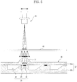
- FIG. 5 is a sectional view illustrating a portion of a microfluidic system according to another exemplary embodiment.
- This exemplary embodiment is the same as the exemplary embodiment illustrated in FIG. 2 except that a lens is added and thus integrated with the microfluidic device.
- the microfluidic system 10 according to the exemplary embodiment shown in FIG. 5 may be provided with a lens 81, performing the same functions as the lens 80 shown in FIG. 4 , which is integrated with a substrate 92.
- the microfluidic device 90 eliminates the necessity of mounting the lens and a lens barrel on the external surface thereof and the lens 81 can be formed integrally with the first substrate 22a by injection molding, thus enabling reduction of manufacturing costs of the microfluidic system.
- FIG. 6 is a sectional view illustrating a portion of a microfluidic system according to another exemplary embodiment.
- This exemplary embodiment is the same as the exemplary embodiment illustrated in FIG. 2 except that a diffuser 61 is integrated with the microfluidic device 100.
- the microfluidic system 10 may be provided with the diffuser 61 which is integrated with the upper surface of a first substrate 102a of the microfluidic device 100.
- a diffuser having superior light-emission capabilities can uniformize light diffusion and light intensity even at a short distance. For this reason, the diffuser 61 integrates with the first substrate 102a, thus reducing manufacturing costs of the microfluidic system 10.
- the diffuser 61 can be provided on the substrate 22 by sand-blasting, integrally molding the substrate provided with a diffuser using a surface-treated die used for injection molding performed on the substrate, or applying a light-diffusion material to the substrate or adhering a light-diffusion film thereto.
- FIG. 7 is a sectional view illustrating a portion of a microfluidic system according to another exemplary embodiment.
- This exemplary embodiment is the same as the exemplary embodiment illustrated in FIG. 2 except that a lens is provided and a position of a diffuser is different.
- the microfluidic system 10 may be provided with a light irradiation apparatus 150 including a diffuser 153 and a lens 155. That is, the diffuser 153 is arranged under the light source 151 such that it is near the light source 151, and a lens 155 to concentrate light emitted from the diffuser 153 is arranged in a lower region of the diffuser 153.
- the diffuser 153 and the lens 155 are provided in the light irradiation apparatus 150 such that they are arranged near the light source 151, to minimize stray light diverged to the outside of irradiation regions and thereby maximize light efficiency.
- valve 36 can be operated even by a low output light source, and the diffuser 153 and the lens 155 can be directly adhered to the light irradiation apparatus 150, thus reducing manufacturing costs of the microfluidic system 10. Beam size and orientation angle can be minimized and effects of stray light on reagents or fluids provided near the valve 36 can thus be minimized.
- FIG. 8 is a sectional view illustrating a portion of a microfluidic system according to another exemplary embodiment.
- This exemplary embodiment is the same as the exemplary embodiment illustrated in FIG. 2 except that a light guide unit 200 is used as a diffuser to emit light.
- the light guide unit 200 may be a light pipe or an optical fiber.
- the light guide unit 200 guides light of the light irradiation apparatus 50 to irradiation regions of the microfluidic device 20 to uniformize light intensity distribution of the light source.
- the input terminal of the light guide unit 200 extends to the side of the light source of the light irradiation apparatus 50 and the output terminal thereof extends to the side of irradiation regions of the microfluidic device 20.
- Light irradiated from the light source to the light guide unit 200 does not escape outside and is guided, while being repeatedly reflected, and is then uniformly distributed.
- the light guide unit 200 such as a light pipe or an optical fiber is composed of a flexible material and may thus be deformed. For this reason, when the position of the output terminal is controlled regardless of the position of the light source, light with substantially uniform intensity distribution can be supplied to irradiation regions of the microfluidic device 20 using the light guide unit 200.
- the following operation method is applicable to the afore-mentioned embodiments of the microfluidic system.
- the microfluidic system 10 attains position information of the valve 36 to be opened and position information of the chamber 32 containing fluid samples to be heated, included in the microfluidic device 20.
- a variety of methods for obtaining position information may be utilized. For example, position information of the microfluidic structure 30 in the microfluidic device 20 used for an information storing portion (not shown) of the microfluidic system 10 is pre-stored, and when each microfluidic device 20 is considered to be mounted on the spindle 40, position information of the microfluidic structure 30 present in the corresponding microfluidic device 20 is loaded and then used for system operation.
- the microfluidic system 10 can obtain information for subsequent operations only by confirming the position of a base point.
- the microfluidic device 20 can obtain position information of the valve 36, the channel 34, or the chamber 32 by imparting reference numerals to the valve 36, the channel 34, or the chamber 32 or a position corresponding thereto and allowing the microfluidic system 10 to recognize the reference numerals.
- the light irradiation apparatus 50 is pointed towards at least one valve 36 or the chamber 32 containing a fluid sample A using position information thus obtained.
- the pointing of the light irradiation apparatus 50 is carried out by detecting deviation between the position of the valve 36 selected on the microfluidic device 20 (or the position of the chamber 32 containing a fluid sample) and the position to which electromagnetic waves of the external energy source reach, based on a pointing initiation time, and controlling the target of the electromagnetic waves within the deviation using the spindle 40 and the position adjustment unit of the light irradiation apparatus.
- the microfluidic device 20 forwardly and reversely rotates using the spindle 40, such that the light irradiation apparatus 50 and the valve 36 (or chamber 32) are arranged at the equal angle, and the light irradiation apparatus 50 is moved in a radial direction using the position adjustment unit of the light irradiation apparatus, to allow the light irradiation apparatus 50 to aim at the selected valve.
- Selection of the valve 36 (or chamber 32), that the light irradiation apparatus 50 targets, is carried out by user input, or a preset program.
- control through programs is preferable.
- the irradiated light is diffused through the diffuser 60, energy is supplied to the selected valve 36 or chamber 32 by the diffused light and the phase transition material is homogeneously melted, to open the channel 34, or a fluid sample A is uniformly heated by the microfluidic heat-generating material P distributed in the fluid sample A of the chamber 32.
- light irradiated from the light irradiation apparatus 50 is uniformly supplied through the diffuser 60 to the chamber 32, thus uniformly heating fluid samples and thereby imparting an optimum temperature suitable for required tests to the fluid samples.
- a microfluidic system provided with a single light irradiation apparatus is illustrated in the afore-mentioned exemplary embodiments, a plurality of light irradiation apparatuses including a single light source and diffusers equal in number to the number of the light irradiation apparatuses in one microfluidic system may be provided.
Landscapes
- Engineering & Computer Science (AREA)
- General Engineering & Computer Science (AREA)
- Chemical & Material Sciences (AREA)
- Dispersion Chemistry (AREA)
- Mechanical Engineering (AREA)
- Health & Medical Sciences (AREA)
- Toxicology (AREA)
- Analytical Chemistry (AREA)
- General Health & Medical Sciences (AREA)
- Hematology (AREA)
- Clinical Laboratory Science (AREA)
- Chemical Kinetics & Catalysis (AREA)
- Physical Or Chemical Processes And Apparatus (AREA)
- Automatic Analysis And Handling Materials Therefor (AREA)
Description
- Apparatuses and methods consistent with exemplary embodiments relate to a microfluidic device, a light irradiation apparatus, a microfluidic system including the same, and a method for driving the same, and more specifically, to a microfluidic device, a light irradiation apparatus, a microfluidic system including the same, and a method for driving the same, to uniformly heat a fluid sample present in the microfluidic device or smoothly operate a valve.
- Generally, microfluidic devices used for operations utilizing a small amount of fluid include a chamber to retain a small amount of fluid, a channel through which the fluid flows, and a valve to control fluid flow. A device to perform experiments including biochemical reactions on a small chip is referred to as a biochip, in particular, a device wherein treatment and operations of fluids through a series of steps are performed on one chip is referred to as a lab-on-a-chip.
- A driving pressure is required to transfer fluids in a microfluidic device. Capillary pressure or pressure applied by an additional pump is used as driving pressure. Recently, a disc-shaped microfluidic device, called a "Lab CD" or "Lab-on-a-CD" in which chambers and channels are arranged rotates to operate fluids through centrifugal force.
- Various valve techniques to control fluid flows in these microfluidic devices are being researched. At present, thermally activated valves using a material to undergo phase-transition from solid to liquid utilizing heat generated by absorbance of electromagnetic waves are being developed.
- Operations of thermally activated valves sensitively depend on characteristics of a light source to transfer light energy to a valve material and light energy absorbance efficiency of the valve material.
- First, when light energy absorbance efficiency of the valve material is low, light irradiation for a long time and high light source output are disadvantageously required in order to cause phase-transition of the valve material.
- When light energy absorbance efficiency of the valve material is high, excessively long light irradiation time makes the valve material excessively hot, thus causing serious deformation of a substrate and biochemical variation of sample fluids adjacent to the valve material due to heat conduction. On the other hand, excessively short light irradiation time provides insufficient phase-transition, thus disadvantageously causing incomplete opening/closing of the valve.
- In addition, since related art light sources may have non-uniform light intensity distribution, a portion of the valve may be excessively heated or not heated, although light irradiation time is accurately controlled, thus providing incomplete phase-transition. In particular, for example, these problems may be more serious in valve materials exhibiting poor heat conductivity such as paraffin.
- There are differences in light intensity distribution between light sources having identical specifications. For this reason, disadvantageously, microfluidic devices separately using a plurality of light sources have different valve operation characteristics. In addition, upon mass-production of microfluidic devices, it is not easy to impart identical valve operation performance to the microfluidic devices due to the differences in light intensity distribution between light sources provided in the respective microfluidic devices.
- For accurate testing of fluid samples accepted in microfluidic devices, the temperature of fluid samples required for the desired tests may be varied.
- When the fluid sample temperature is lower than a desired test temperature, heating of the sample fluid is required to elevate the fluid sample temperature to a desired level. In this case, when light intensity distribution of light sources is non-uniform, uniform elevation of the fluid sample temperature is disadvantageously impossible.
- In addition, uniform heating of fluid samples is required to perform a variety of tests such as acceleration of reactions of fluid samples with other materials, culturing of cells contained in fluid samples, extraction of nucleic acid through cell lysis, amplification of nucleic acid through polymerase chain reaction (PCR) cycles and the like. Similarly, non-uniform light intensity distribution of light sources disadvantageously makes uniform elevation of fluid sample temperature impossible.
-
US 2008/274015 A1 discloses a microfluidic system with a rotatable disc-substrate, a spindle motor, and an energy source as for example a laser light source. The microfluidic device comprises a microfluidic structure with a chamber, a channel, and a valve. There are different examples for means influencing the laser light projected from the laser light source as for example a convex lens, a concave lens and the like. -
WO 2007/060523 A1 discloses a microfluidic structure with actuator components such as an injection pump. There is a microfluidic channel, a one-way valve and other means as well as means for optical measurement. Those means are in particular used for the purpose of an optical fluid detection. -
WO 2005/098431 A1 discloses a device for determining concentration for particular substances. Then, analyte test strip is used which comprises a hollow cavity, a sample distribution system and the like. The detector arrangement is used for measuring optical density of a corresponding sample which comprises a light source and may also comprise a diffuser or lens. - It is an object of the present invention to provide a microfluidic device to uniformly heat a fluid sample present in the microfluidic device and to accurately control operation of a valve present in the microfluidic device, such that temperature of a fluid sample contained in the chamber of the microfluidic device is uniformly elevated.
- This object is solved by the features of the claims.
- The diffuser may be arranged on a light path between the light irradiation apparatus and the microfluidic device.
- The diffuser may be arranged on the microfluidic device.
- The diffuser may be formed by a method selected from sand-blasting, injection molding using a surface-treated die, applying a light-diffusion material to the substrate, adhering a light-diffusion film thereto and combinations thereof.
- The diffuser may be mounted on the light irradiation apparatus.
- The irradiation region may include at least one of the chamber containing a fluid sample and the valve.
- The microfluidic system may further include: a mask to prevent light of the light irradiation apparatus from being irradiated outside of the irradiation region of the microfluidic device.
- The mask may be made of a material absorbing or reflecting light.
- The lens may be adhered to a surface of the microfluidic device, or injection-molded integrally with the substrate.
- The diffuser may include a light guide unit to receive light energy from the light irradiation apparatus and emit the light to the irradiation region.
- The light guide unit may be a light pipe or an optical fiber.
- The diffuser may include at least one of injected materials including ground glasses, sand-blasted glass/polymer, opal glasses, light-diffusion films and light-diffusion materials.
- The light source of the light irradiation apparatus may be a laser, an LED, or a lamp operating at 0.1 Watts to 10 Watts.
- The substrate may be a disc-shaped revolving body and further include a spindle to rotate the microfluidic device, and the microfluidic device may operate based on centrifugal force generated by rotation of the spindle, enabling the fluid sample to pass through the channel.
- In accordance with an aspect of another exemplary embodiment, there is provided a microfluidic system including: a microfluidic device including a chamber containing a fluid sample, a channel enabling flow of the fluid sample, and a valve composed of a phase transition material to absorb light and then melt to control flow of the fluid sample passing through the channel; a light source to irradiate light energy to the valve; and a diffuser to diffuse light energy irradiated from the light source to allow the phase transition material to homogeneously melt.
- The valve may further include microfluidic heat-generating materials, which are dispersed in the phase-transition material and absorb microwave energy irradiated from the outside and generate heat.
- The microfluidic heat-generating material may be selected from the group consisting of polymer beads, quantum dots, gold (Au) nanoparticles, silver (Ag) nanoparticles, metal composite beads and magnetic beads and combinations thereof.
- The microfluidic heat-generating material may be a metal oxide particle.
- The microfluidic heat-generating material may include a dye emitting light in response to electromagnetic irradiation.
- The phase transition material may be selected from waxes, gels, thermoplastic resins and combinations thereof.
- The wax may be selected from the group consisting of paraffin waxes, microcrystalline waxes, synthetic waxes, natural waxes and combinations thereof.
- The gel may include at least one selected from polyacrylamides, polyacrylates, polymethacrylates and polyvinylamides.
- The thermoplastic resin may include at least one selected from cyclic olefin copolymers (COCs), polymethylmethacrylate (PMMA), polycarbonate (PC), polystyrene (PS), polyoxymethylene (POM), perfluoralkoxy (PFA), polyvinylchloride (PVC), polypropylene (PP), polyethylene terephthalate (PET), polyetheretherketone (PEEK), polyamide (PA), polysulfone (PSU), and polyvinylidene fluoride (PVDF).
- The microfluidic system may further include: a lens provided between the diffuser and the valve, to concentrate light passing through the diffuser and irradiate the light to the microfluidic device.
- The diffuser may be arranged near the light source to impart spinning properties similar to a dot light source, to light passing through the diffuser.
- The microfluidic system may further include: a mask to prevent light of the light irradiation apparatus from being irradiated outside of the irradiation region of the microfluidic device.
- In accordance with an aspect of another exemplary embodiment, there is provided a microfluidic device including: a substrate including a microfluidic structure formed therein, the microfluidic structure including a chamber containing a fluid sample, a channel enabling flow of the fluid sample, and a valve composed of a phase transition material which melts upon absorbing energy, to control flow of the fluid sample passing through the channel; and a diffuser to diffuse and thus substantially uniformly distribute light irradiated from the light irradiation apparatus to an irradiation region of the microfluidic device.
- The diffuser may be formed by a method selected from sand-blasting, injection molding using a surface-treated die, applying a light-diffusion material to the substrate, adhering a light-diffusion film thereto and combinations thereof.
- In accordance with an aspect of another exemplary embodiment, there is provided a light irradiation apparatus for irradiating light to a microfluidic device including a chamber containing a fluid sample, a channel enabling flow of the fluid sample, and a valve to control flow of the fluid sample passing through the channel, the light irradiation apparatus including: a light source and a diffuser to diffuse and thus substantially uniformly distribute light irradiated from the light source to an irradiation region of the microfluidic device.
- The light irradiation apparatus may further include: a lens provided between the diffuser and the valve, to concentrate light passing through the diffuser and irradiate the light to the microfluidic device.
- The diffuser may include a light guide unit to receive light energy from the light irradiation apparatus and emit the light to the irradiation region.
- In accordance with an aspect of another exemplary embodiment, there is provided a method for driving a microfluidic system including: obtaining position information of the chamber containing a fluid sample; aiming the light irradiation apparatus at the selected at least one fluid sample and irradiating light thereto by operating the spindle using the position information; diffusing the irradiated light using the diffuser; and supplying energy to a fluid sample contained in at least one chamber by the diffused light.
- In accordance with an aspect of another exemplary embodiment, there is provided a method for driving a microfluidic system including: attaining position information of the chamber containing a fluid sample; aiming the light source at the selected at least one fluid sample and irradiating light thereto by operating the spindle using the position information; diffusing the irradiated light using the diffuser; and supplying energy to a fluid sample contained in at least one chamber by the diffused light to melt the phase transition material.
- The aiming the light source at the fluid sample and irradiating light thereto may be carried out by rotating the substrate and moving the light source in a reverse diameter direction from an upper portion of the substrate.
- The above and/or other aspects will become apparent and more readily appreciated from the following description of exemplary embodiments, taken in conjunction with the accompanying drawings of which:
-
FIG. 1 is a perspective view illustrating a microfluidic system according to an exemplary embodiment; -
FIG. 2 is a sectional view illustrating a portion of a microfluidic system according to an exemplary embodiment; -
FIG. 3 is a view illustrating operation of the microfluidic system according to an exemplary embodiment; -
FIG. 4 is a sectional view illustrating a portion of a microfluidic system according to another exemplary embodiment; -
FIG. 5 is a sectional view illustrating a portion of a microfluidic system according to another exemplary embodiment; -
FIG. 6 is a sectional view illustrating a portion of a microfluidic system according to another exemplary embodiment; -
FIG. 7 is a sectional view illustrating a portion of a microfluidic system according to another exemplary embodiment; and -
FIG. 8 is a sectional view illustrating a portion of a microfluidic system according to another exemplary embodiment. - A microfluidic device, a light irradiation apparatus, a microfluidic system including the same, and a method for driving the same according to exemplary embodiments will be described in detail with reference to the accompanying drawings, wherein like reference numerals refer to like elements throughout.
- Structures such as chambers and channels illustrated in the drawings may have a simplified shape and be exaggerated or reduced in scale. The prefix "micro" of expressions such as "micro-fluidic device" or "micro-particle" only means the opposite of "macro", and is not to be construed as being limited to a specific size unit.
-
FIG. 1 is a perspective view illustrating a microfluidic system according to an exemplary embodiment,FIG. 2 is a sectional view illustrating a portion of a microfluidic system according to an exemplary embodiment, andFIG. 3 is a view illustrating operation of the microfluidic system according to an exemplary embodiment. - Referring to
FIG. 1 , themicrofluidic system 10 according to an exemplary embodiment includes amicrofluidic device 20 provided with achamber 32, achannel 34 and avalve 36, aspindle 40 to rotate themicrofluidic device 20, alight irradiation apparatus 50 to irradiate themicrofluidic device 20, and adiffuser 60 to diffuse and substantially uniformly distribute light irradiated from thelight irradiation apparatus 50 to an irradiation region of themicrofluidic device 20. - The
microfluidic device 20 includes a disc-shapedrotatable substrate 22 and amicrofluidic structure 30 provided in thesubstrate 22. - The
substrate 22 can be readily molded and may be provided with a surface made of a biologically inert plastic material such as acryl or PDMS. Materials for the substrate are not limited thereto, and exhibit superior chemical and biological stability, as well as excellent optical transmission and mechanical processability. - The
substrate 22 may be composed of a plurality of layers of plates, and grooves are formed in regions, where chambers or channels are formed, on the surface wherein adjacent plates come in contact with each other, and the grooves are joined together to providechambers 32 andchannels 34 in thesubstrate 22. - For example, the
substrate 22 includes afirst substrate 22a and asecond substrate 22b adhered to thefirst substrate 22a. Thefirst substrate 22a and thesecond substrate 22b are composed of a thermoplastic resin. - The
first substrate 22a to thesecond substrate 22b may be adhered together by various methods such as adhesion using an adhesive agent or a double-sided adhesive tape, or fusion through, for example, ultrasonic wave fusion or laser fusion. - The
microfluidic structure 30 includes at least onechamber 32 to accomodate a fluid sample, achannel 34 through which the fluid sample flows, connected to thechamber 32, and thevalve 36 including a phase-transition material V that melts upon absorbing light energy, to control flow of the fluid sample which passes through thechannel 34. - In addition, the
microfluidic device 20 is mounted on thespindle 40 which rotates themicrofluidic device 20 at a high speed. Themicrofluidic device 20 has ahole 21 at the center thereof, enabling themicrofluidic device 20 to be mounted on thespindle 40. The centrifugal force generated by rotation of thespindle 40 causes fluids in thechamber 32 or thechannel 34 of themicrofluidic device 20 to be forced towards the perimeter of thesubstrate 22. - In the
microfluidic device 20, locations of thechamber 32, thechannel 34 and thevalve 36 are determined depending on desired biochemical applications such as centrifugation, immune serum reactions, and gene analysis, extraction and amplification of fluid samples. - That is, the
chamber 32, thechannel 34 and thevalve 36 provided in themicrofluidic structure 30 according to an exemplary embodiment are symbolically simplified from various shapes of structures which may be practically provided, inFIGs. 1 and2 , and the shape and structure of themicrofluidic structure 30 is not limited to the shape and structure shown in the exemplary embodiment and may be designed to have various shapes according to applications thereof. - The
microfluidic structure 30 is provided with at least twochambers 32 which serve as a storage chamber, a mixing chamber, a reaction chamber and a culture chamber. - The
valve 36 may be provided in a region in which thechamber 32 contacts thechannel 34 or in the middle of thechannel 34 of themicrofluidic device 20, and thechannel 34 is provided in the middle of thechannel 34 in an exemplary embodiment. - As shown in
FIG. 1 , thevalve 36 is a thermally activated valve composed of a material containing the phase transition material V with a high melting point, and a plurality of microfluidic heat-generating materials P dispersed in the phase-transition material V, to absorb microwave energy irradiated from the outside and generate heat. - The fluid sample may be kept under conditions suitable for desired functions at a predetermined temperature, whereas the microfluidic heat-generating materials P are dispersed or aggregated in the fluid sample, to absorb energy irradiated from the outside of the
microfluidic device 20 and transfer the same to adjacent samples, thereby increasing the temperature of the fluid sample. - The phase transition material with the dispersed microfluidic heat-generating materials P, for example, is injected in a molten phase into the
channel 34 using a dispenser (not shown) and cured to cause the channel to close. - The phase transition material V of the
valve 36 may be a wax, which is melted, liquidated and expanded upon heating. Examples of applicable waxes include paraffin waxes, microcrystalline waxes, synthetic waxes, natural waxes and the like. - The phase transition material V may be a gel or a thermoplastic resin. Examples of useful gels include polyacrylamides, polyacrylates, polymethacrylates, polyvinylamides and the like. In addition, examples of useful thermoplastic resins include cyclic olefin copolymers (COCs), polymethylmethacrylate (PMMA), polycarbonate (PC), polystyrene (PS), polyoxymethylene (POM), perfluoralkoxy (PFA), polyvinylchloride (PVC), polypropylene (PP), polyethylene terephthalate (PET), polyetheretherketone (PEEK), polyamide (PA), polysulfone (PSU), polyvinylidene fluoride (PVDF) and the like.
- The microfluidic heat-generating materials P may have a diameter of 1 nm to 100 µm so that they readily pass through the
fine channels 34. For example, the microfluidic heat-generating materials P undergo rapid temperature elevation to emit heat, when electromagnetic energy is supplied by a method such as laser irradiation and are homogeneously distributed in the phase transition material. As such, the microfluidic heat-generating materials P may have a core-shell structure including a core containing a metal and a hydrophobic shell. For example, the microfluidic heat-generating materials P include a core composed of iron (Fe) and a plurality of surfactants bound to iron (Fe) to surround the iron (Fe). - The microfluidic heat-generating materials P may be stored in the form of a dispersion in a carrier oil. The carrier oil may be hydrophobic, to allow the microfluidic heat-generating materials P with a hydrophobic surface to be homogeneously distributed. The carrier oil, in which the microfluidic heat-generating materials P are dispersed, is added into the melted phase transition material V and the materials P are mixed with each other to prepare a valve material.
- The microfluidic heat-generating materials P are not limited to polymer beads mentioned above, and may be quantum dots, magnetic beads, gold (Au) nanoparticles, silver (Ag) nanoparticles, beads composed of a metal composition or carbon particles. The carbon particles include graphite particles. In addition, the fine heat-emitting particles P, for example, may be metal oxide particles such as Al2O3, TiO2, Ta2O3, Fe2O3, Fe3O4 or HfO2.
- In addition, the microfluidic heat-generating material P may be a dye which absorbs a predetermined spectrum of external electromagnetic waves and emits heat. Any dye may be used so long as it has a molecular structure miscible with the phase transition material. Examples of useful dyes include dyes with optical properties such as ADS905AM, infrared dyes with chemical formula C62H96N6SbF6 or infrared dyes (Epolight2057) available from American Dye Source Inc., infrared dyes available from Epolin Inc. with an absorption spectrum suitable for near infrared light sources, and dyes such as Epolight2180, Epolight2189, carbon black and the like.
- The
microfluidic system 10 includes thelight irradiation apparatus 50 to irradiate electromagnetic waves and thus supply energy to a fluid sample accepted in thechamber 32 or thevalve 36. - The
light irradiation apparatus 50 irradiates electromagnetic waves with a predetermined wavelength selected from various wavelengths of electromagnetic waves such as microwave, infrared, visible, ultraviolet and X-rays. - In addition, the
light irradiation apparatus 50 may intensely irradiate these electromagnetic waves near targets and may have a wavelength range in which the microfluidic heat-generating material P absorbs energy well. For thelight irradiation apparatus 50, factors such as light sources to generate electromagnetic waves, and wavelength and output thereof may be determined depending on ingredients of and surface conditions of microfluidic heat-generating materials P contained in the microfluidic device. - The light source of the light irradiation apparatus, for example, may have an output of 0.1 Watts to 10 Watts, and may be a laser light source to irradiate laser beams, a light emitting diode to irradiate visible or infrared light or a xenon lamp (Xenon). The laser light source may include at least one laser diode.
- The
microfluidic system 10 may include a position adjustment unit (not shown) to control the position and/or direction of thelight irradiation apparatus 50 and thus intensely transfer electromagnetic waves emitted therefrom to a desired region of themicrofluidic device 20. In an exemplary embodiment, the position adjustment unit moves thelight irradiation apparatus 50 in the arrow direction represented in an upper portion of thelight irradiation apparatus 50, that is, in a radial direction of the disc-shapedmicrofluidic device 20. The position adjustment unit, which causes thelight irradiation apparatus 50 to move along a straight line, may be realized through various mechanisms, is apparent to those skilled in the art and a detailed explanation thereof is thus omitted. - In addition, the
spindle 40 rotates themicrofluidic device 20. Although not illustrated in the drawings, themicrofluidic system 10 includes a motor to rotate themicrofluidic device 20 at a constant speed in a forward or reverse direction, that is, at a predetermined speed and at a predetermined angle, if necessary, and one or more elements related to the motor. Similar to the position adjustment unit (not shown) of thelight irradiation apparatus 50, a detailed explanation of thespindle 40 is omitted. - In the
microfluidic system 10 shown inFIG. 1 , thelight irradiation apparatus 50 intensively irradiates electromagnetic waves to irradiation regions of themicrofluidic device 20, that is, thechambers 32 containing fluid samples to be irradiated and/or thevalves 36. - The
microfluidic system 10 includes adiffuser 60 to diffuse light energy irradiated from thelight irradiation apparatus 50 to irradiation regions of themicrofluidic structure 30 and thus uniformly distribute the light thereto. - As shown in
FIGs. 1 and2 , thediffuser 60 may be provided in the form of a long rectangle in a lower region of thelight irradiation apparatus 50 to cover the lower region of a flow path of the position adjustment unit of the light irradiation apparatus. - For example, the
diffuser 60 is provided on a light path formed between thelight irradiation apparatus 50 and themicrofluidic device 20. - The diffuser (i.e., light diffusion medium) diffuses light emitted from a predetermined direction to various directions. For this reason, after passing through the
diffuser 60, light has an increased diffusion angle and decreased light intensity variation according to diffusion angles, as shown inFIG. 2 . - In an exemplary embodiment, the
diffuser 60 may be positioned in a region provided between thelight irradiation apparatus 50 and themicrofluidic device 20. However, thediffuser 60 may be positioned in themicrofluidic device 20, that is, near the side of thefirst substrate 22a, when it has high diffusion capability, and themicrofluidic device 20 may be positioned near a light source of thelight irradiation apparatus 50, when it has low diffusion capability. As the distance between thediffuser 60 and themicrofluidic device 20 increases, light intensity distribution becomes more uniform, but light energy loss may increase. Through various tests, a suitable position of thediffuser 60 may be optimized. - For example, the
diffuser 60 may be a medium selected from ground glass, sand-blasted glass/polymer, opal glass, light-diffusion films for a liquid crystal display (LCD) backlight unit (BLU), light-diffusion films for LCD protection and various kinds of light-diffusion resins. - Next, a microfluidic device and a microfluidic system including the same according to another embodiment will be described.
-
FIG. 4 is a sectional view illustrating a portion of a microfluidic system according to another exemplary embodiment. - The exemplary embodiment illustrated in
FIG. 4 is the same as the exemplary embodiment illustrated inFIG. 2 except that amask 70 and alens 80 are further provided. - The following other exemplary embodiments employ elements different from those of the exemplary embodiment of
FIG. 2 and the same elements are denoted by the same reference numerals and a detailed explanation thereof is thus omitted. - The
microfluidic system 10 shown inFIG. 4 further includes themask 70 provided with a window having a size corresponding to or larger than the size of thevalve 36, and thelens 80, provided between thediffuser 60 and thevalve 36, to focus light emitted from thediffuser 60. Themask 70 may be composed of a material or structure to absorb or reflect light to prevent light diverged to the outside of irradiation regions from being irradiated to themicrofluidic device 20. As shown inFIG. 4 , themask 70 is realized on the upper surface of thefirst substrate 22a, may be integrated with themicrofluidic device 20 and may be provided in an area provided between thediffuser 60 and themicrofluidic device 20. - The
lens 80 may be provided in the form of a convex lens between thediffuser 60 and thevalve 36, to concentrate light, which passes through thediffuser 60 and is then emitted, on the side of thevalve 36 and thus improve light efficiency, thereby enabling reliable operation of thevalve 36, although a low output laser light source is used. - A light-concentration level can be optimized by suitably setting the focus distance and position of the
lens 80. - The
microfluidic system 10 may be provided with both amask 70 and alens 80, as shown inFIG. 4 , and may be provided with either themask 70 or thelens 80. - Next, a microfluidic device and a microfluidic system including the same according to another exemplary embodiment will be described.
-
FIG. 5 is a sectional view illustrating a portion of a microfluidic system according to another exemplary embodiment. - This exemplary embodiment is the same as the exemplary embodiment illustrated in
FIG. 2 except that a lens is added and thus integrated with the microfluidic device. - The
microfluidic system 10 according to the exemplary embodiment shown inFIG. 5 may be provided with alens 81, performing the same functions as thelens 80 shown inFIG. 4 , which is integrated with asubstrate 92. - Accordingly, the
microfluidic device 90 eliminates the necessity of mounting the lens and a lens barrel on the external surface thereof and thelens 81 can be formed integrally with thefirst substrate 22a by injection molding, thus enabling reduction of manufacturing costs of the microfluidic system. - Next, a microfluidic device and a microfluidic system including the same according to another exemplary embodiment will be described.
-
FIG. 6 is a sectional view illustrating a portion of a microfluidic system according to another exemplary embodiment. - This exemplary embodiment is the same as the exemplary embodiment illustrated in
FIG. 2 except that adiffuser 61 is integrated with themicrofluidic device 100. - The
microfluidic system 10 according to the exemplary embodiment shown inFIG. 6 may be provided with thediffuser 61 which is integrated with the upper surface of afirst substrate 102a of themicrofluidic device 100. - A diffuser having superior light-emission capabilities can uniformize light diffusion and light intensity even at a short distance. For this reason, the
diffuser 61 integrates with thefirst substrate 102a, thus reducing manufacturing costs of themicrofluidic system 10. - For example, the
diffuser 61 can be provided on thesubstrate 22 by sand-blasting, integrally molding the substrate provided with a diffuser using a surface-treated die used for injection molding performed on the substrate, or applying a light-diffusion material to the substrate or adhering a light-diffusion film thereto. - Next, a light irradiation apparatus and a microfluidic system including the same according to another exemplary embodiment will be described.
-
FIG. 7 is a sectional view illustrating a portion of a microfluidic system according to another exemplary embodiment. - This exemplary embodiment is the same as the exemplary embodiment illustrated in
FIG. 2 except that a lens is provided and a position of a diffuser is different. - The
microfluidic system 10 according to the exemplary embodiment shown inFIG. 7 may be provided with alight irradiation apparatus 150 including adiffuser 153 and alens 155. That is, thediffuser 153 is arranged under thelight source 151 such that it is near thelight source 151, and alens 155 to concentrate light emitted from thediffuser 153 is arranged in a lower region of thediffuser 153. - The
diffuser 153 and thelens 155 are provided in thelight irradiation apparatus 150 such that they are arranged near thelight source 151, to minimize stray light diverged to the outside of irradiation regions and thereby maximize light efficiency. - Accordingly, the
valve 36 can be operated even by a low output light source, and thediffuser 153 and thelens 155 can be directly adhered to thelight irradiation apparatus 150, thus reducing manufacturing costs of themicrofluidic system 10. Beam size and orientation angle can be minimized and effects of stray light on reagents or fluids provided near thevalve 36 can thus be minimized. - Next, a light irradiation apparatus and a microfluidic system including the same according to another exemplary embodiment will be described.
-
FIG. 8 is a sectional view illustrating a portion of a microfluidic system according to another exemplary embodiment. - This exemplary embodiment is the same as the exemplary embodiment illustrated in
FIG. 2 except that alight guide unit 200 is used as a diffuser to emit light. - For example, the
light guide unit 200 may be a light pipe or an optical fiber. Thelight guide unit 200 guides light of thelight irradiation apparatus 50 to irradiation regions of themicrofluidic device 20 to uniformize light intensity distribution of the light source. - The input terminal of the
light guide unit 200 extends to the side of the light source of thelight irradiation apparatus 50 and the output terminal thereof extends to the side of irradiation regions of themicrofluidic device 20. - Light irradiated from the light source to the
light guide unit 200 does not escape outside and is guided, while being repeatedly reflected, and is then uniformly distributed. Thelight guide unit 200 such as a light pipe or an optical fiber is composed of a flexible material and may thus be deformed. For this reason, when the position of the output terminal is controlled regardless of the position of the light source, light with substantially uniform intensity distribution can be supplied to irradiation regions of themicrofluidic device 20 using thelight guide unit 200. - Hereinafter, a method for driving a microfluidic system according to an exemplary embodiment will be described with reference to
FIGS. 2 and3 . - The following operation method is applicable to the afore-mentioned embodiments of the microfluidic system.
- First, when the
microfluidic device 20 is mounted on thespindle 40 of themicrofluidic system 10, themicrofluidic system 10 attains position information of thevalve 36 to be opened and position information of thechamber 32 containing fluid samples to be heated, included in themicrofluidic device 20. A variety of methods for obtaining position information may be utilized. For example, position information of themicrofluidic structure 30 in themicrofluidic device 20 used for an information storing portion (not shown) of themicrofluidic system 10 is pre-stored, and when eachmicrofluidic device 20 is considered to be mounted on thespindle 40, position information of themicrofluidic structure 30 present in the correspondingmicrofluidic device 20 is loaded and then used for system operation. In this case, themicrofluidic system 10 can obtain information for subsequent operations only by confirming the position of a base point. As another example, themicrofluidic device 20 can obtain position information of thevalve 36, thechannel 34, or thechamber 32 by imparting reference numerals to thevalve 36, thechannel 34, or thechamber 32 or a position corresponding thereto and allowing themicrofluidic system 10 to recognize the reference numerals. - Next, the
light irradiation apparatus 50 is pointed towards at least onevalve 36 or thechamber 32 containing a fluid sample A using position information thus obtained. - The pointing of the
light irradiation apparatus 50 is carried out by detecting deviation between the position of thevalve 36 selected on the microfluidic device 20 (or the position of thechamber 32 containing a fluid sample) and the position to which electromagnetic waves of the external energy source reach, based on a pointing initiation time, and controlling the target of the electromagnetic waves within the deviation using thespindle 40 and the position adjustment unit of the light irradiation apparatus. For example, themicrofluidic device 20 forwardly and reversely rotates using thespindle 40, such that thelight irradiation apparatus 50 and the valve 36 (or chamber 32) are arranged at the equal angle, and thelight irradiation apparatus 50 is moved in a radial direction using the position adjustment unit of the light irradiation apparatus, to allow thelight irradiation apparatus 50 to aim at the selected valve. Selection of the valve 36 (or chamber 32), that thelight irradiation apparatus 50 targets, is carried out by user input, or a preset program. In particular, in the case where themicrofluidic device 20 includes a plurality ofvalves 36 andchambers 32 and these elements sequentially operate, control through programs is preferable. - Next, light is irradiated to the targeted valve 36 (or chamber 32).
- The irradiated light is diffused through the
diffuser 60, energy is supplied to the selectedvalve 36 orchamber 32 by the diffused light and the phase transition material is homogeneously melted, to open thechannel 34, or a fluid sample A is uniformly heated by the microfluidic heat-generating material P distributed in the fluid sample A of thechamber 32. - Accordingly, light irradiated from the
light irradiation apparatus 50 is supplied through thediffuser 60 to thevalve 36 and the microfluidic heat-generating material P of thevalve 36 is thus heated, to accurately control operations of thevalve 36, and the deviation between a plurality of light sources of thelight irradiation apparatus 50 causes uniform operation of thevalve 36. - In addition, light irradiated from the
light irradiation apparatus 50 is uniformly supplied through thediffuser 60 to thechamber 32, thus uniformly heating fluid samples and thereby imparting an optimum temperature suitable for required tests to the fluid samples. - Although a microfluidic system provided with a single light irradiation apparatus is illustrated in the afore-mentioned exemplary embodiments, a plurality of light irradiation apparatuses including a single light source and diffusers equal in number to the number of the light irradiation apparatuses in one microfluidic system may be provided.
- Accordingly, when a plurality of light irradiation apparatuses having a single light source are provided in the microfluidic system and a plurality of light sources are simultaneously used, operation conditions of the light sources can be uniformized. As a result, valve operation characteristics can be secured and a predetermined temperature can thus be imparted to fluid samples although light intensities of light sources are varied.
- In addition, difference in valve operation characteristics between a plurality of microfluidic systems using an identical light source and difference in temperature between fluid samples can be minimized.
- Although a few exemplary embodiments have been shown and described, it would be appreciated by those skilled in the art that changes may be made in these embodiments without departing from the principles of the inventive concept, the scope of which is defined in the claims.
Claims (13)
- A microfluidic system (10) comprising:a microfluidic device (20, 90, 100) comprising a chamber (32) containing a fluid sample, a channel (34) enabling flow of the fluid sample, and a valve (35) to control flow of the fluid sample passing through the channel;a light irradiation apparatus (50, 150) to irradiate light energya diffuser (60, 61, 153, 200) to diffuse and thus substantially uniformly distribute light irradiated from the light irradiation apparatus (50, 150) to an irradiation region of the microfluidic device characterized in thata lens (80, 81, 155) is provided between the diffuser (60, 153) and the valve (35) adapted to concentrate light passing through the diffuser and to irradiate the light to the microfluidic device.
- The microfluidic system according to claim 1, wherein the diffuser (60, 61, 153, 200) is arranged in a light path between the light irradiation apparatus (50, 150) and the microfluidic device (20, 90, 100).
- The microfluidic system according to claim 1, wherein the diffuser (61) is arranged on the microfluidic device (100).
- The microfluidic system according to claim 3, wherein the diffuser (61) is formed by a method selected from sand-blasting, injection molding using a surface-treated die, applying a light-diffusion material to themicrofluidic device, adhering a light-diffusion film thereto and combinations thereof.
- The microfluidic system according to claim 1, wherein the diffuser (153, 200) is mounted on the light irradiation apparatus (50, 150).
- The microfluidic system according to claim 1, wherein the irradiation region includes at least one of the chamber (32) containing a fluid sample and the valve (36).
- The microfluidic system according to claim 1, further comprising:a mask (70) to prevent light of the light irradiation apparatus (50) from being irradiated outside of the irradiation region of the microfluidic device (20).
- The microfluidic system according to claim 7, wherein the mask (70) is made of a material absorbing or reflecting light.
- The microfluidic system according to claim 1, wherein the lens (80, 81, 155) is adhered to a surface of the microfluidic device (90), or injection-molded integrally with the microfluidic device.
- The microfluidic system according to claim 1, wherein the diffuser comprises a light guide unit (200) to receive light energy from the light irradiation apparatus (50) and emit the light to the irradiation region.
- The microfluidic system according to claim 10, wherein the light guide unit (200) is a light pipe or an optical fiber.
- The microfluidic system according to claim 1, wherein the diffuser (60, 61, 153) includes at least one of injected materials including ground glass, sand-blasted glass/polymer, opal glass, light-diffusion films and light-diffusion materials.
- The microfluidic system according to claim 1, wherein the light source (50, 150) of the light irradiation apparatus is a laser, a light emitting diode, or a lamp operating at 0.1 Watts to 10 Watts.
Applications Claiming Priority (1)
| Application Number | Priority Date | Filing Date | Title |
|---|---|---|---|
| KR1020090112881A KR20110056168A (en) | 2009-11-20 | 2009-11-20 | Microfluidic device, light irradiation device, microfluidic system including the same and driving method thereof |
Publications (3)
| Publication Number | Publication Date |
|---|---|
| EP2324924A2 EP2324924A2 (en) | 2011-05-25 |
| EP2324924A3 EP2324924A3 (en) | 2013-12-25 |
| EP2324924B1 true EP2324924B1 (en) | 2017-10-18 |
Family
ID=43608870
Family Applications (1)
| Application Number | Title | Priority Date | Filing Date |
|---|---|---|---|
| EP10190865.5A Not-in-force EP2324924B1 (en) | 2009-11-20 | 2010-11-11 | Microfluidic system |
Country Status (4)
| Country | Link |
|---|---|
| US (1) | US9057456B2 (en) |
| EP (1) | EP2324924B1 (en) |
| KR (1) | KR20110056168A (en) |
| CN (1) | CN102071242A (en) |
Families Citing this family (26)
| Publication number | Priority date | Publication date | Assignee | Title |
|---|---|---|---|---|
| US9370628B2 (en) * | 2011-06-05 | 2016-06-21 | University Of British Columbia | Wireless microactuators and control methods |
| TWI470224B (en) * | 2011-12-22 | 2015-01-21 | Univ Chang Gung | Detecting system and detecting method |
| EP2811952A1 (en) * | 2012-02-07 | 2014-12-17 | On Demand Therapeutics, Inc. | Drug delivery devices and methods of use thereof |
| TWI456196B (en) | 2012-04-24 | 2014-10-11 | Ind Tech Res Inst | Immunoassay test apparatus |
| KR20140009607A (en) * | 2012-07-11 | 2014-01-23 | 삼성전자주식회사 | Test device and control method thereof |
| KR101347373B1 (en) * | 2012-07-17 | 2014-01-06 | 국립대학법인 울산과학기술대학교 산학협력단 | Microfluidic device havimg valve, and fabricating mehtod thereof |
| KR101497193B1 (en) * | 2012-12-31 | 2015-03-03 | 고려대학교 산학협력단 | Apparatus and method for monitoring platelet function and drug response using centrifugation-based microfluidics |
| KR20140147536A (en) * | 2013-06-20 | 2014-12-30 | 삼성디스플레이 주식회사 | Light irradiation device and fabrication method for display device using the same |
| US10183290B2 (en) * | 2015-04-16 | 2019-01-22 | Advanced Technology Applications, Llc | Method for analyte examination |
| CN106816672A (en) * | 2015-12-01 | 2017-06-09 | 认知控管株式会社 | The preheating device of Electrically-driven vehicle battery |
| CN110291396B (en) * | 2016-10-07 | 2021-02-26 | 刘新宇 | Microfluidic analytical platform for autonomous immunoassays |
| CN121825134A (en) | 2017-02-09 | 2026-04-10 | 吉昂功能材料(东莞)有限公司 | Heat conductive polyvinyl halides |
| US10811285B2 (en) * | 2017-05-31 | 2020-10-20 | Taiwan Semiconductor Manufacturing Company, Ltd. | Vapor shield replacement system and method |
| EP3450960A1 (en) * | 2017-09-04 | 2019-03-06 | Biosurfit, S.A. | Detection system |
| KR20190043876A (en) * | 2017-10-19 | 2019-04-29 | 연세대학교 산학협력단 | Magnetic Labelling/Staining device using Magnetic Nano Particles |
| WO2019187294A1 (en) * | 2018-03-30 | 2019-10-03 | 富士フイルム株式会社 | Tip, mixing device, and mixing method |
| CN108489608B (en) * | 2018-06-01 | 2023-11-03 | 东莞东阳光医疗智能器件研发有限公司 | Light detection device |
| CN108679301B (en) * | 2018-09-06 | 2019-01-08 | 湖南乐准智芯生物科技有限公司 | Shielding system, control method and biochip between a kind of micro-valve and liquid |
| KR102073387B1 (en) * | 2019-08-19 | 2020-02-05 | 삼성디스플레이 주식회사 | Light irradiation device and fabrication method for display device using the same |
| CN112138735A (en) * | 2020-09-12 | 2020-12-29 | 深圳市和来生物技术有限公司 | Heating, temperature detection and optical detection device and method for micro-fluidic chip |
| KR102597565B1 (en) * | 2021-05-03 | 2023-11-06 | 성균관대학교산학협력단 | Pcr apparatus |
| EP4282948A1 (en) * | 2022-05-27 | 2023-11-29 | Finnadvance Oy | Cell culture apparatus and method |
| KR102839509B1 (en) * | 2022-07-20 | 2025-07-25 | 연세대학교 산학협력단 | Optofluidic Biochip for Controlling Fluid based on Optics and Methods of Manufacturing and Fluid Control Thereof |
| TWI849643B (en) * | 2022-12-23 | 2024-07-21 | 國立成功大學 | Improved structure of quantitative molecular detection chip |
| CN116574603B (en) * | 2023-07-14 | 2023-09-19 | 潍坊安普未来生物科技有限公司 | Isothermal amplification detection device and detection method |
| CN119972211B (en) * | 2025-02-18 | 2025-10-17 | 天府绛溪实验室 | Device for driving liquid to rotate by laser |
Family Cites Families (30)
| Publication number | Priority date | Publication date | Assignee | Title |
|---|---|---|---|---|
| US5709670A (en) * | 1994-05-03 | 1998-01-20 | Aquintel, Inc. | Surgical fluid and tissue loss monitor |
| US20020151078A1 (en) * | 2000-05-15 | 2002-10-17 | Kellogg Gregory J. | Microfluidics devices and methods for high throughput screening |
| KR100432438B1 (en) * | 2001-01-18 | 2004-05-22 | 주식회사 송산 | Prism Diffuser |
| US20050009101A1 (en) * | 2001-05-17 | 2005-01-13 | Motorola, Inc. | Microfluidic devices comprising biochannels |
| US6734436B2 (en) * | 2001-08-07 | 2004-05-11 | Sri International | Optical microfluidic devices and methods |
| AU2003224817B2 (en) * | 2002-04-01 | 2008-11-06 | Fluidigm Corporation | Microfluidic particle-analysis systems |
| AU2003302264A1 (en) * | 2002-12-20 | 2004-09-09 | Biotrove, Inc. | Assay apparatus and method using microfluidic arrays |
| CA2772050C (en) * | 2002-12-26 | 2016-09-06 | Meso Scale Technologies, Llc. | Assay cartridges and methods of using the same |
| JP2004317891A (en) * | 2003-04-17 | 2004-11-11 | Nec Saitama Ltd | Mobile electronic equipment with camera |
| US20050174251A1 (en) * | 2004-02-02 | 2005-08-11 | Terry Robert L.Iii | Wall supported fire and smoke alarm having laser light |
| ATE385572T1 (en) | 2004-03-05 | 2008-02-15 | Egomedical Swiss Ag | ANALYTE TEST SYSTEM FOR DETERMINING THE CONCENTRATION OF AN ANALYTE IN A PHYSIOLOGICAL LIQUID |
| US7359124B1 (en) * | 2004-04-30 | 2008-04-15 | Louisiana Tech University Research Foundation As A Division Of The Louisiana Tech University Foundation | Wide-angle variable focal length lens system |
| JP2006039463A (en) * | 2004-07-30 | 2006-02-09 | Dainippon Printing Co Ltd | Transmission screen |
| EP1650297B1 (en) * | 2004-10-19 | 2011-04-13 | Samsung Electronics Co., Ltd. | Method and apparatus for the rapid disruption of cells or viruses using micro magnetic beads and laser |
| US20070121113A1 (en) * | 2004-12-22 | 2007-05-31 | Cohen David S | Transmission-based optical detection systems |
| KR100647317B1 (en) * | 2005-02-03 | 2006-11-23 | 삼성전자주식회사 | Optical system for measuring multi-channel fluorescence and multi-channel fluorescence sample analyzer |
| US20060257290A1 (en) * | 2005-04-13 | 2006-11-16 | Fuji Photo Film Co., Ltd. | Fluid dispenser, fluid dispensing method and assay apparatus for assay in utilizing attenuated total reflection |
| US7527763B2 (en) * | 2005-07-05 | 2009-05-05 | 3M Innovative Properties Company | Valve control system for a rotating multiplex fluorescence detection device |
| US20090165876A1 (en) | 2005-11-22 | 2009-07-02 | Micah James Atkin | Microfluidic Structures |
| KR100851980B1 (en) | 2006-09-05 | 2008-08-12 | 삼성전자주식회사 | Centrifugal force based microfluidic device having heat-activative unit, microfluidic system comprinsing the same and method for driving the system |
| WO2008106782A1 (en) * | 2007-03-02 | 2008-09-12 | Universite Laval | Serial siphon valves for fluidic or microfluidic devices |
| KR101258434B1 (en) * | 2007-05-03 | 2013-05-02 | 삼성전자주식회사 | Microfluidic system and fabricating method of the same |
| KR101410752B1 (en) * | 2007-07-20 | 2014-06-23 | 삼성전자 주식회사 | An optical detection device, an optical detection method, and a microfluidic system including the optical detection device |
| JP2009157356A (en) * | 2007-12-04 | 2009-07-16 | Nippon Shokubai Co Ltd | Light diffusing plate and method of manufacturing light diffusing plate |
| US8143600B2 (en) * | 2008-02-18 | 2012-03-27 | Visiongate, Inc. | 3D imaging of live cells with ultraviolet radiation |
| KR100911567B1 (en) * | 2008-04-29 | 2009-08-10 | 현대자동차주식회사 | Vehicle dashboard |
| JP2010205713A (en) * | 2008-06-27 | 2010-09-16 | Seiko Instruments Inc | Lighting device, and display device using the same |
| EP2163306A1 (en) * | 2008-09-12 | 2010-03-17 | F. Hoffmann-la Roche AG | Multi-well plate with tailored chambers |
| KR20100039707A (en) * | 2008-10-08 | 2010-04-16 | 삼성전자주식회사 | Beam radiating device, bio-chemical analyzer with the beam radiating device, and bio-chemical analyzing system with the bio-chemical analyzer |
| JP4860013B2 (en) * | 2009-08-17 | 2012-01-25 | 三菱電機株式会社 | Display device |
-
2009
- 2009-11-20 KR KR1020090112881A patent/KR20110056168A/en not_active Abandoned
-
2010
- 2010-11-05 US US12/940,092 patent/US9057456B2/en active Active
- 2010-11-11 EP EP10190865.5A patent/EP2324924B1/en not_active Not-in-force
- 2010-11-17 CN CN2010105474453A patent/CN102071242A/en active Pending
Non-Patent Citations (1)
| Title |
|---|
| None * |
Also Published As
| Publication number | Publication date |
|---|---|
| KR20110056168A (en) | 2011-05-26 |
| EP2324924A2 (en) | 2011-05-25 |
| US9057456B2 (en) | 2015-06-16 |
| CN102071242A (en) | 2011-05-25 |
| US20110121196A1 (en) | 2011-05-26 |
| EP2324924A3 (en) | 2013-12-25 |
Similar Documents
| Publication | Publication Date | Title |
|---|---|---|
| EP2324924B1 (en) | Microfluidic system | |
| US7951332B2 (en) | Centrifugal force based microfluidic device for dilution and microfluidic system including the same | |
| US9101935B2 (en) | Microfluidic apparatus and control method thereof | |
| KR101130698B1 (en) | Valve unit, microfluidic device including the same, and driving method of the valve unit | |
| US7981385B2 (en) | Microfluidic device and microfluidic system with the same | |
| US20080058192A1 (en) | Centrifugal force based microfluidic device having thermal activation unit, microfluidic system including the same and method of operating the microfluidic system | |
| EP1980322B1 (en) | Centrifugal force-based microfluidic device and microfluidic system | |
| US8048387B2 (en) | Centrifugal microfluidic device having sample distribution structure and centrifugal microfluidic system including the centrifugal microfluidic device | |
| US8333935B2 (en) | Microfluidic device using microfluidic chip and microfluidic device using biomolecule microarray chip | |
| EP1920843A1 (en) | Valve unit, microfluidic device with the valve unit, and microfluidic substrate | |
| US20120261026A1 (en) | Microfluidic device | |
| US20110091356A1 (en) | Micro-fluidic device and sample testing method using the same |
Legal Events
| Date | Code | Title | Description |
|---|---|---|---|
| PUAI | Public reference made under article 153(3) epc to a published international application that has entered the european phase |
Free format text: ORIGINAL CODE: 0009012 |
|
| AK | Designated contracting states |
Kind code of ref document: A2 Designated state(s): AL AT BE BG CH CY CZ DE DK EE ES FI FR GB GR HR HU IE IS IT LI LT LU LV MC MK MT NL NO PL PT RO RS SE SI SK SM TR |
|
| AX | Request for extension of the european patent |
Extension state: BA ME |
|
| RAP1 | Party data changed (applicant data changed or rights of an application transferred) |
Owner name: SAMSUNG ELECTRONICS CO., LTD. |
|
| PUAL | Search report despatched |
Free format text: ORIGINAL CODE: 0009013 |
|
| AK | Designated contracting states |
Kind code of ref document: A3 Designated state(s): AL AT BE BG CH CY CZ DE DK EE ES FI FR GB GR HR HU IE IS IT LI LT LU LV MC MK MT NL NO PL PT RO RS SE SI SK SM TR |
|
| AX | Request for extension of the european patent |
Extension state: BA ME |
|
| RIC1 | Information provided on ipc code assigned before grant |
Ipc: F16K 99/00 20060101ALI20131120BHEP Ipc: B01L 3/00 20060101AFI20131120BHEP |
|
| 17P | Request for examination filed |
Effective date: 20140625 |
|
| RBV | Designated contracting states (corrected) |
Designated state(s): AL AT BE BG CH CY CZ DE DK EE ES FI FR GB GR HR HU IE IS IT LI LT LU LV MC MK MT NL NO PL PT RO RS SE SI SK SM TR |
|
| GRAP | Despatch of communication of intention to grant a patent |
Free format text: ORIGINAL CODE: EPIDOSNIGR1 |
|
| INTG | Intention to grant announced |
Effective date: 20170425 |
|
| RIN1 | Information on inventor provided before grant (corrected) |
Inventor name: SHIN, YONG MOO Inventor name: LEE, JONG GUN Inventor name: KIM, JIN TAE Inventor name: YEO, YEONG BAE Inventor name: PARK, JONG MYEON |
|
| GRAS | Grant fee paid |
Free format text: ORIGINAL CODE: EPIDOSNIGR3 |
|
| GRAA | (expected) grant |
Free format text: ORIGINAL CODE: 0009210 |
|
| AK | Designated contracting states |
Kind code of ref document: B1 Designated state(s): AL AT BE BG CH CY CZ DE DK EE ES FI FR GB GR HR HU IE IS IT LI LT LU LV MC MK MT NL NO PL PT RO RS SE SI SK SM TR |
|
| REG | Reference to a national code |
Ref country code: GB Ref legal event code: FG4D |
|
| REG | Reference to a national code |
Ref country code: CH Ref legal event code: EP |
|
| REG | Reference to a national code |
Ref country code: AT Ref legal event code: REF Ref document number: 937471 Country of ref document: AT Kind code of ref document: T Effective date: 20171115 Ref country code: IE Ref legal event code: FG4D |
|
| REG | Reference to a national code |
Ref country code: FR Ref legal event code: PLFP Year of fee payment: 8 |
|
| REG | Reference to a national code |
Ref country code: DE Ref legal event code: R096 Ref document number: 602010046017 Country of ref document: DE |
|
| REG | Reference to a national code |
Ref country code: NL Ref legal event code: MP Effective date: 20171018 |
|
| REG | Reference to a national code |
Ref country code: LT Ref legal event code: MG4D |
|
| REG | Reference to a national code |
Ref country code: AT Ref legal event code: MK05 Ref document number: 937471 Country of ref document: AT Kind code of ref document: T Effective date: 20171018 |
|
| PG25 | Lapsed in a contracting state [announced via postgrant information from national office to epo] |
Ref country code: NL Free format text: LAPSE BECAUSE OF FAILURE TO SUBMIT A TRANSLATION OF THE DESCRIPTION OR TO PAY THE FEE WITHIN THE PRESCRIBED TIME-LIMIT Effective date: 20171018 |
|
| PG25 | Lapsed in a contracting state [announced via postgrant information from national office to epo] |
Ref country code: ES Free format text: LAPSE BECAUSE OF FAILURE TO SUBMIT A TRANSLATION OF THE DESCRIPTION OR TO PAY THE FEE WITHIN THE PRESCRIBED TIME-LIMIT Effective date: 20171018 Ref country code: NO Free format text: LAPSE BECAUSE OF FAILURE TO SUBMIT A TRANSLATION OF THE DESCRIPTION OR TO PAY THE FEE WITHIN THE PRESCRIBED TIME-LIMIT Effective date: 20180118 Ref country code: LT Free format text: LAPSE BECAUSE OF FAILURE TO SUBMIT A TRANSLATION OF THE DESCRIPTION OR TO PAY THE FEE WITHIN THE PRESCRIBED TIME-LIMIT Effective date: 20171018 Ref country code: FI Free format text: LAPSE BECAUSE OF FAILURE TO SUBMIT A TRANSLATION OF THE DESCRIPTION OR TO PAY THE FEE WITHIN THE PRESCRIBED TIME-LIMIT Effective date: 20171018 Ref country code: SE Free format text: LAPSE BECAUSE OF FAILURE TO SUBMIT A TRANSLATION OF THE DESCRIPTION OR TO PAY THE FEE WITHIN THE PRESCRIBED TIME-LIMIT Effective date: 20171018 |
|
| PG25 | Lapsed in a contracting state [announced via postgrant information from national office to epo] |
Ref country code: AT Free format text: LAPSE BECAUSE OF FAILURE TO SUBMIT A TRANSLATION OF THE DESCRIPTION OR TO PAY THE FEE WITHIN THE PRESCRIBED TIME-LIMIT Effective date: 20171018 Ref country code: BG Free format text: LAPSE BECAUSE OF FAILURE TO SUBMIT A TRANSLATION OF THE DESCRIPTION OR TO PAY THE FEE WITHIN THE PRESCRIBED TIME-LIMIT Effective date: 20180118 Ref country code: RS Free format text: LAPSE BECAUSE OF FAILURE TO SUBMIT A TRANSLATION OF THE DESCRIPTION OR TO PAY THE FEE WITHIN THE PRESCRIBED TIME-LIMIT Effective date: 20171018 Ref country code: IS Free format text: LAPSE BECAUSE OF FAILURE TO SUBMIT A TRANSLATION OF THE DESCRIPTION OR TO PAY THE FEE WITHIN THE PRESCRIBED TIME-LIMIT Effective date: 20180218 Ref country code: GR Free format text: LAPSE BECAUSE OF FAILURE TO SUBMIT A TRANSLATION OF THE DESCRIPTION OR TO PAY THE FEE WITHIN THE PRESCRIBED TIME-LIMIT Effective date: 20180119 Ref country code: HR Free format text: LAPSE BECAUSE OF FAILURE TO SUBMIT A TRANSLATION OF THE DESCRIPTION OR TO PAY THE FEE WITHIN THE PRESCRIBED TIME-LIMIT Effective date: 20171018 Ref country code: LV Free format text: LAPSE BECAUSE OF FAILURE TO SUBMIT A TRANSLATION OF THE DESCRIPTION OR TO PAY THE FEE WITHIN THE PRESCRIBED TIME-LIMIT Effective date: 20171018 |
|
| REG | Reference to a national code |
Ref country code: DE Ref legal event code: R097 Ref document number: 602010046017 Country of ref document: DE |
|
| PG25 | Lapsed in a contracting state [announced via postgrant information from national office to epo] |
Ref country code: CZ Free format text: LAPSE BECAUSE OF FAILURE TO SUBMIT A TRANSLATION OF THE DESCRIPTION OR TO PAY THE FEE WITHIN THE PRESCRIBED TIME-LIMIT Effective date: 20171018 Ref country code: LI Free format text: LAPSE BECAUSE OF NON-PAYMENT OF DUE FEES Effective date: 20171130 Ref country code: SK Free format text: LAPSE BECAUSE OF FAILURE TO SUBMIT A TRANSLATION OF THE DESCRIPTION OR TO PAY THE FEE WITHIN THE PRESCRIBED TIME-LIMIT Effective date: 20171018 Ref country code: MC Free format text: LAPSE BECAUSE OF FAILURE TO SUBMIT A TRANSLATION OF THE DESCRIPTION OR TO PAY THE FEE WITHIN THE PRESCRIBED TIME-LIMIT Effective date: 20171018 Ref country code: CH Free format text: LAPSE BECAUSE OF NON-PAYMENT OF DUE FEES Effective date: 20171130 Ref country code: DK Free format text: LAPSE BECAUSE OF FAILURE TO SUBMIT A TRANSLATION OF THE DESCRIPTION OR TO PAY THE FEE WITHIN THE PRESCRIBED TIME-LIMIT Effective date: 20171018 Ref country code: EE Free format text: LAPSE BECAUSE OF FAILURE TO SUBMIT A TRANSLATION OF THE DESCRIPTION OR TO PAY THE FEE WITHIN THE PRESCRIBED TIME-LIMIT Effective date: 20171018 |
|
| PLBE | No opposition filed within time limit |
Free format text: ORIGINAL CODE: 0009261 |
|
| STAA | Information on the status of an ep patent application or granted ep patent |
Free format text: STATUS: NO OPPOSITION FILED WITHIN TIME LIMIT |
|
| PG25 | Lapsed in a contracting state [announced via postgrant information from national office to epo] |
Ref country code: RO Free format text: LAPSE BECAUSE OF FAILURE TO SUBMIT A TRANSLATION OF THE DESCRIPTION OR TO PAY THE FEE WITHIN THE PRESCRIBED TIME-LIMIT Effective date: 20171018 Ref country code: IT Free format text: LAPSE BECAUSE OF FAILURE TO SUBMIT A TRANSLATION OF THE DESCRIPTION OR TO PAY THE FEE WITHIN THE PRESCRIBED TIME-LIMIT Effective date: 20171018 Ref country code: PL Free format text: LAPSE BECAUSE OF FAILURE TO SUBMIT A TRANSLATION OF THE DESCRIPTION OR TO PAY THE FEE WITHIN THE PRESCRIBED TIME-LIMIT Effective date: 20171018 Ref country code: LU Free format text: LAPSE BECAUSE OF NON-PAYMENT OF DUE FEES Effective date: 20171111 Ref country code: SM Free format text: LAPSE BECAUSE OF FAILURE TO SUBMIT A TRANSLATION OF THE DESCRIPTION OR TO PAY THE FEE WITHIN THE PRESCRIBED TIME-LIMIT Effective date: 20171018 |
|
| REG | Reference to a national code |
Ref country code: BE Ref legal event code: MM Effective date: 20171130 |
|
| REG | Reference to a national code |
Ref country code: IE Ref legal event code: MM4A |
|
| 26N | No opposition filed |
Effective date: 20180719 |
|
| PG25 | Lapsed in a contracting state [announced via postgrant information from national office to epo] |
Ref country code: MT Free format text: LAPSE BECAUSE OF NON-PAYMENT OF DUE FEES Effective date: 20171111 |
|
| PG25 | Lapsed in a contracting state [announced via postgrant information from national office to epo] |
Ref country code: IE Free format text: LAPSE BECAUSE OF NON-PAYMENT OF DUE FEES Effective date: 20171111 |
|
| PG25 | Lapsed in a contracting state [announced via postgrant information from national office to epo] |
Ref country code: SI Free format text: LAPSE BECAUSE OF FAILURE TO SUBMIT A TRANSLATION OF THE DESCRIPTION OR TO PAY THE FEE WITHIN THE PRESCRIBED TIME-LIMIT Effective date: 20171018 Ref country code: BE Free format text: LAPSE BECAUSE OF NON-PAYMENT OF DUE FEES Effective date: 20171130 |
|
| PGFP | Annual fee paid to national office [announced via postgrant information from national office to epo] |
Ref country code: DE Payment date: 20181126 Year of fee payment: 9 |
|
| PGFP | Annual fee paid to national office [announced via postgrant information from national office to epo] |
Ref country code: FR Payment date: 20181130 Year of fee payment: 9 Ref country code: GB Payment date: 20181120 Year of fee payment: 9 |
|
| PG25 | Lapsed in a contracting state [announced via postgrant information from national office to epo] |
Ref country code: HU Free format text: LAPSE BECAUSE OF FAILURE TO SUBMIT A TRANSLATION OF THE DESCRIPTION OR TO PAY THE FEE WITHIN THE PRESCRIBED TIME-LIMIT; INVALID AB INITIO Effective date: 20101111 |
|
| PG25 | Lapsed in a contracting state [announced via postgrant information from national office to epo] |
Ref country code: CY Free format text: LAPSE BECAUSE OF NON-PAYMENT OF DUE FEES Effective date: 20171018 |
|
| PG25 | Lapsed in a contracting state [announced via postgrant information from national office to epo] |
Ref country code: MK Free format text: LAPSE BECAUSE OF FAILURE TO SUBMIT A TRANSLATION OF THE DESCRIPTION OR TO PAY THE FEE WITHIN THE PRESCRIBED TIME-LIMIT Effective date: 20171018 |
|
| PG25 | Lapsed in a contracting state [announced via postgrant information from national office to epo] |
Ref country code: TR Free format text: LAPSE BECAUSE OF FAILURE TO SUBMIT A TRANSLATION OF THE DESCRIPTION OR TO PAY THE FEE WITHIN THE PRESCRIBED TIME-LIMIT Effective date: 20171018 |
|
| PG25 | Lapsed in a contracting state [announced via postgrant information from national office to epo] |
Ref country code: PT Free format text: LAPSE BECAUSE OF FAILURE TO SUBMIT A TRANSLATION OF THE DESCRIPTION OR TO PAY THE FEE WITHIN THE PRESCRIBED TIME-LIMIT Effective date: 20171018 |
|
| REG | Reference to a national code |
Ref country code: DE Ref legal event code: R119 Ref document number: 602010046017 Country of ref document: DE |
|
| PG25 | Lapsed in a contracting state [announced via postgrant information from national office to epo] |
Ref country code: AL Free format text: LAPSE BECAUSE OF FAILURE TO SUBMIT A TRANSLATION OF THE DESCRIPTION OR TO PAY THE FEE WITHIN THE PRESCRIBED TIME-LIMIT Effective date: 20171018 |
|
| GBPC | Gb: european patent ceased through non-payment of renewal fee |
Effective date: 20191111 |
|
| PG25 | Lapsed in a contracting state [announced via postgrant information from national office to epo] |
Ref country code: DE Free format text: LAPSE BECAUSE OF NON-PAYMENT OF DUE FEES Effective date: 20200603 Ref country code: FR Free format text: LAPSE BECAUSE OF NON-PAYMENT OF DUE FEES Effective date: 20191130 Ref country code: GB Free format text: LAPSE BECAUSE OF NON-PAYMENT OF DUE FEES Effective date: 20191111 |