EP2324325B1 - Improvements in or relating to vibrating structure gyroscopes - Google Patents
Improvements in or relating to vibrating structure gyroscopes Download PDFInfo
- Publication number
- EP2324325B1 EP2324325B1 EP09785302A EP09785302A EP2324325B1 EP 2324325 B1 EP2324325 B1 EP 2324325B1 EP 09785302 A EP09785302 A EP 09785302A EP 09785302 A EP09785302 A EP 09785302A EP 2324325 B1 EP2324325 B1 EP 2324325B1
- Authority
- EP
- European Patent Office
- Prior art keywords
- annular resonator
- substrate
- transducer
- vibrating structure
- metal track
- Prior art date
- Legal status (The legal status is an assumption and is not a legal conclusion. Google has not performed a legal analysis and makes no representation as to the accuracy of the status listed.)
- Active
Links
Images



Classifications
-
- G—PHYSICS
- G01—MEASURING; TESTING
- G01C—MEASURING DISTANCES, LEVELS OR BEARINGS; SURVEYING; NAVIGATION; GYROSCOPIC INSTRUMENTS; PHOTOGRAMMETRY OR VIDEOGRAMMETRY
- G01C19/00—Gyroscopes; Turn-sensitive devices using vibrating masses; Turn-sensitive devices without moving masses; Measuring angular rate using gyroscopic effects
- G01C19/56—Turn-sensitive devices using vibrating masses, e.g. vibratory angular rate sensors based on Coriolis forces
- G01C19/567—Turn-sensitive devices using vibrating masses, e.g. vibratory angular rate sensors based on Coriolis forces using the phase shift of a vibration node or antinode
- G01C19/5677—Turn-sensitive devices using vibrating masses, e.g. vibratory angular rate sensors based on Coriolis forces using the phase shift of a vibration node or antinode of essentially two-dimensional [2D] vibrators, e.g. ring-shaped vibrators
- G01C19/5684—Turn-sensitive devices using vibrating masses, e.g. vibratory angular rate sensors based on Coriolis forces using the phase shift of a vibration node or antinode of essentially two-dimensional [2D] vibrators, e.g. ring-shaped vibrators the devices involving a micromechanical structure
Definitions
- This invention relates to a vibrating structure gyroscope, which is particularly, but not exclusively, suitable for use as a Coriolis type gyroscope constructed using Micro-Electro-Mechanical Systems techniques.
- Coriolis type gyroscopes fabricated using Micro-Electro-Mechanical Systems (MEMS) technology
- MEMS Micro-Electro-Mechanical Systems
- Coriolis type gyroscopes are now widely used for a range of high volume applications.
- MEMS Micro-Electro-Mechanical Systems
- Such gyroscopes can be utilised in advanced braking systems, active suspension, rollover detection and prevention applications and navigation applications.
- the performance requirements of gyroscopes for such applications are relatively undemanding, particularly when compared to typical aerospace and military applications, where gyroscopes are used for guidance and control.
- MEMS gyroscopes for such applications is largely based on their low cost per unit, which is achieved primarily by the wafer level fabrication techniques of MEMS processing that enables MEMS gyroscopes to be economically produced in large quantities.
- the performance level of MEMS gyroscopes is relatively modest in comparison with other classes of gyroscope, such as spinning wheel or fibre optic gyroscopes.
- the use of higher specification gyroscopes is typically restricted to aerospace and military applications as the unit cost of such gyroscopes is too high to be considered for higher volume automotive and commercial applications.
- the lower performance capability of MEMS gyroscopes prohibits their use in the majority of aerospace and military applications.
- UK patent GB2322196 describes a MEMS gyroscope that is used for automotive and commercial applications.
- the low cost and rugged nature of this MEMS gyroscope makes it attractive for use in guidance and control, navigation and platform stabilisation applications.
- the performance capability particularly in terms of the rate bias stability and signal to noise ratio, is typically insufficient to meet these requirements. It would therefore be advantageous to enhance the performance of such prior art apparatus.
- a known MEMS gyroscope 10 similar to that described in UK patent GB 2322196 , includes a sensing element comprising a planar silicon ring structure 12 that is externally supported by eight compliant legs 14a to 14h. These legs 14a to 14h are in turn attached to a rigid external frame 16.
- the gyroscope 10 is arranged to operate using a cos2 ⁇ vibration mode pair, as illustrated with referenced to Figure 2a and 2b .
- One of the vibration mode pair is excited as a primary carrier mode P, Figure 2a wherein the dotted line indicates the extremes of motion of the ring structure 12 in the primary carrier mode P.
- the primary carrier mode P is generated using at least one drive transducer and the secondary response mode S is detected using at least one pick-off transducer.
- the drive and pick-off transducers are arranged around the ring structure 12.
- metal track 24 is provided on an upper surface of a ring structure 20 and an external frame 22, over an insulating surface oxide layer.
- metal track 24 is repeated for eight circuits, one circuit for each drive and pick-off transducer.
- Each circuit of metal track 24 begins at a first bond-pad 26, runs along a first compliant leg 28, across an eighth segment 30 of the ring structure 20 and back along an adjacent compliant leg 32 to a second bond-pad 34.
- This circuit arrangement is repeated for each eighth segment 30 of the ring structure 20, such that each compliant leg 28 carries a metal track 24 for two adjacent transducers.
- a third metal track 36 is located along the centre of each compliant leg 28, 32, between the metal track 24 associated with adjacent transducers to reduce the cross-coupling effect between circuits associated with adjacent transducers.
- a magnetic field B is applied around the periphery of the ring structure 20 and arranged perpendicular to the plane of the ring structure 20.
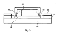
- the magnetic field is applied by a permanent magnet 38, located inside the circumference of the ring structure 20, and an upper pole piece 40 and lower pole piece 42 which are arranged to concentrate the magnetic field in a gap between the pole pieces 40, 42, in the vicinity of the periphery of the ring structure 20.
- the ring structure 20, compliant legs 28, 32 and external frame 22 are bonded onto a supporting glass substrate 44. This assembly is in turn bonded onto a glass support structure 46 together with the permanent magnet 38 and pole pieces 40, 42, which are assembled with the ring structure 20 located in the gap between the upper and lower pole piece 40, 42.
- V vBL
- v the peak velocity of the vibratory motion of the metal track 24 in the magnetic field
- B the magnetic field
- L the length of metal track 24 in the magnetic field.
- Such a MEMS gyroscope 10 will typically be operated in a closed loop mode of operation.
- the primary carrier mode P is driven at the resonance maximum using a primary drive transducer controlled by a Phase Locked Loop.
- the amplitude of motion of the ring structure 12 is maintained at a constant value by an Automatic Gain Control loop, which is arranged to compare the amplitude of motion of the ring structure 12, as measured at a primary pick-off transducer, to a fixed reference level and to dynamically adjust a drive signal to the primary drive transducer to maintain a constant signal level and hence a constant amplitude of motion of the ring structure 12.
- the magnitude of the Coriolis force induced when the ring structure 12 is rotated about the axis 18 normal to the plane of the ring structure 12, and hence the scalefactor of the MEMS gyroscope 10 is directly proportional to the amplitude of the primary carrier mode P motion.
- the Coriolis force will induce motion in the secondary response mode S, which is detected by a secondary pick-off transducer.
- the secondary response mode S motion is nulled by an appropriately controlled secondary drive transducer.
- the drive force required to maintain the null condition of the secondary response mode S provides a direct representation of the rotation rate applied about the axis 18.
- rate bias error there are a number of possible sources of rate bias error for a MEMS gyroscope 10.
- the two most significant errors for a MEMS gyroscope 10 are known to be the quadrature bias error, which arises due to imperfections in the geometry of the ring structure 12, and the cross-coupling error, which arises due to direct coupling of the primary drive signal into the secondary pick-off signal detected in a rate channel.
- a primary drive force applied by the primary drive transducer will excite both the primary carrier P and secondary response S modes to some extent.
- a phase locked loop circuit associated with the primary drive transducer will adjust the drive frequency to achieve a 90° phase shift between the primary carrier P and the secondary response S modes.
- motion will exist along the axis of the secondary response mode S that will be predominantly in quadrature phase with respect to the primary carrier mode P. In a closed loop system this motion will be nulled by a quadrature force component applied by the secondary drive transducer.
- Quadrature bias, ⁇ QUAD can be large in comparison to the rate signals that the MEMS gyroscope is required to measure.
- a typical rate measurement range for a MEMS gyroscope 10 used in an automotive application is ⁇ 100°/sec.
- the quadrature bias, ⁇ Q UAD if scaled in degrees per second, can be large, for example greater than ⁇ 100°/sec, in comparison to the rate signal and can vary significantly over the operating temperature range of the MEMS gyroscope 10.
- ⁇ E phase error
- ⁇ Err K ⁇ ⁇ ⁇ F ⁇ sin 4 ⁇ ⁇ ⁇ sin ⁇ E
- phase error ⁇ E
- ⁇ QUAD quadrature bias
- the phase error, ⁇ E will typically be relatively stable over the operating temperature range of the MEMS gyroscope 10.
- the quadrature bias, ⁇ QUAD will typically vary by a significant amount. This large variation results in a correspondingly large variation in the quadrature bias error and hence an instability in the rate bias performance.
- a third metal track 36 connected to ground is arranged between the two parallel metal tracks 24 to minimise the direct capacitive coupling between the metal tracks 24.
- This mechanism is known to contribute to rate bias, for example between 1 and 2 degrees per second of rate bias at ambient temperature. This value will scale as 1/Q 2 and the Quality Factor, Q, will vary by a significant amount, i.e. ⁇ 50%, over the operating temperature range of the MEMS gyroscope 10. Therefore, this mechanism makes a significant contribution to the rate bias variation over temperature, which, due to its non-linear nature, is difficult to compensate.
- GB2322196A discloses a vibrating structure gyroscope with eight compliant legs supporting a resonator and carrying electromagnetic drive means and sensors.
- the actuator and sensor tracks are on a common leg and are isolated from each other by intermediate tracks. This feature tends to increase the width of the legs.
- WO0120257A discloses a vibrating structure gyroscope with eight compliant legs supporting a resonator and piezoelectric actuators and sensors.
- magnetic transducers are employed with pairs of legs carrying the transducer conductors and straddling nodes of the resonator.
- the legs are not symmetric.
- GB 2276976A discloses A vibrating structure gyroscope, including:
- the present invention provides a vibrating structure gyroscope as in the above summary of GB 2276976A , characterised in that said at least one pick-off transducer is located in said magnetic field and has a continuous metal track comprising a first track section running from the substrate along the first leg member, along a section of the annular resonator and along the second leg member back to the substrate, said first and second leg members only carrying the metal track associated with a single pick-off transducer.
- the above magnetic pick-off transducer has the advantage over the capacitive transducer utilised in GB 2276976A that the symmetry of the legs can be improved, since each leg can carry a conductor track whereas in GB '976A, of the pairs legs forming a capacitive pick-off transducer, only one carries a conductor track.
- the continuous metal track further comprises at least a second track section continuing from the substrate along the first leg member, along a section of the annular resonator and along the second leg member back to the substrate, said track sections being connected in series and laterally spaced apart from each other.
- This feature enhances the driving oscillation and the pick-off sensitivity and hence increases the signal-to-noise ratio.
- each leg member includes a first radial section extending inwardly from said substrate, a circumferential section, and a second radial section arranged such that the first radial section and second radial section are connected to one another via the circumferential section, and the second radial section is connected to the external periphery of the annular resonator with said circumferential section located outside said magnetic field.
- This leg configuration is highly compliant and ensures that the current flowing through the circumferential section does not interfere with the motor or generator action of the current flowing through the track which runs along the section of the annular resonator. Furthermore the first radial sections, located outside the magnetic field, similarly do not cause any interference with the in-plane radial oscillation of the annular resonator and the effects of currents flowing in both the first and second radial sections, being antiparallel, tend to cancel each other.
- said second radial sections of the respective leg members are spaced apart with a spacing greater than the length of the second radial sections.
- This feature tends to maximise the length of the track portion which runs along the section of the annular resonator and which generates the desired motor action (in a drive transducer) or signal (in a pick-off transducer) in relation to the length of the radial sections and their associated conductor tracks, which do not.
- said first radial sections of said respective leg members are spaced apart with a spacing which is less than the length of said first radial sections.
- This feature tends to maximise the inductive cancellation of the currents running along the first radial sections.
- the flexible supports are preferably equiangularly spaced about the annular resonator.
- At least one primary drive transducer is arranged to cause the annular resonator to oscillate in a primary mode at the resonant frequency of the primary mode
- at least one primary pick-off transducer is arranged to detect oscillation of the annular resonator in the primary mode and to maintain the annular resonator at the resonant frequency of the primary mode
- at least one secondary pick-off transducer is arranged to detect oscillation of a secondary mode induced when angular velocity is applied around the axis substantially perpendicular to the annular resonator and at least one secondary drive transducer is arranged to null the induced secondary mode oscillation.
- the annular resonator, substrate and support arrangement may be arranged substantially in the same plane as one another.
- the drive and pick-off transducers may be arranged substantially coplanar with one another and with the substrate.
- the leg members may optionally be supported at one end from a central hub of the substrate located internally of the annular resonator and each leg member connected at the other end to the internal periphery of the annular resonator.
- each leg member may be supported at one end from the substrate externally of the annular resonator and each leg member connected at the other end to the external periphery of the annular resonator.
- the substrate may be sealed to form a sealed cavity encapsulating the annular resonator, the support arrangement and the drive and pick-off transducers.
- the support arrangement, annular resonator and substrate may be formed from silicon and an insulating layer may be arranged between metal tracks and the support arrangement, annular resonator and substrate.
- the variation in the quadrature bias for the prior art MEMS gyroscope 10 described with reference to Figures 1 to 4 is caused by variation in the frequency split of the primary carrier P and secondary response S mode frequencies and the position of the secondary response mode S over temperature.
- the differential expansion between the silicon of the external frame 22 and the glass support structure 46 tends to distort the external frame 22. This in turn distorts the compliant legs 14a to 14h in such a way that the primary carrier P and secondary response S modes are differentially perturbed thus affecting their frequencies and mode alignment with respect to the ring structure or annular resonator 12.
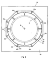
- a vibrating structure gyroscope 50 includes a planar silicon ring structure 52 that is externally supported by a support arrangement 54 having eight flexible supports 56a to 56h arranged to retain the ring structure within a substrate defining a rigid external frame 58.
- Each flexible support 56a to 56h includes a pair of compliant legs 60a and 60b that are attached at one end to the external periphery of the ring structure 52 and at the other end to the internal periphery of the external frame 58.
- each compliant leg 60a, 60b are symmetrical to one another and each compliant leg 60a, 60b includes a first radial section 62, an arcuate section 64 and a second radial section 66 arranged such that the first radial section 62 and second radial section 66 are connected to one another via the arcuate section 64, the first radial section 62 is connected to the internal periphery of the external frame 58 and the second radial section 66 is connected to the external periphery of the ring structure 52.
- the first and second radial sections provide compliance in the tangential direction (to ensure sensitivity to rotation about axis 68) and arcuate section 64 provides compliance in the radial direction.
- the close spacing (preferably less than half their length) of the first radial sections 62 ensures that the inductive effects of currents through their associated metal track portions (shown in Figure 7 ) are cancelled.
- ring structure 52, external frame 58 and support arrangement 54 can all be formed from a single substrate of silicon material using MEMS manufacturing techniques.
- the effect of distortion of the compliant legs 60a and 60b and its consequential effect on the alignment of the frequencies of the primary carrier and secondary response modes with respect to the ring structure 52 is reduced as the in-plane stiffness of the compliant legs 60a and 60b is reduced, thus isolating the ring structure 52 to a greater degree from external stress and strain.
- This is achieved by reducing the width of the compliant legs 60a and 60b.
- the use of a pair of compliant legs 60a and 60b will maintain the out of plane stiffness provided by the compliant legs 60a and 60b.
- the maintenance of a high out of plane stiffness is advantageous as this limits the motion of the ring structure 52 in response to shock and vibration inputs applied along an axis 68 normal to the plane of the ring structure 52. This is beneficial as it reduces the sensitivity of the vibrating structure gyroscope 50 to externally applied mechanical disturbances.
- the support arrangement 54 illustrated in Figure 5 has eight flexible supports 56a to 56h equiangularly spaced about the ring structure 52, each flexible support 56a, 56h having two compliant legs 60a, 60b, arranged as symmetric pairs with a combined in-plane stiffness that is significantly reduced compared to that described with reference to Figures 1 to 4 .
- This provides enhanced isolation from thermally induced stress and strain and maintains the out of plane stiffness required to minimise sensitivity to shock and vibration.
- the in-plane stiffness of an individual compliant leg 60a, 60b will vary approximately in proportion to the width of the compliant leg 60a, 60b cubed. Conversely, the out of plane stiffness varies linearly with the width of the compliant leg 60a, 60b.
- the width of the compliant leg 60a, 60b reduces the in-plane stiffness.
- the width of the compliant legs 14a to 14h for the device described in UK patent GB2322196 is nominally 60 micrometres compared to a width of 20 micrometres for the compliant legs 60a, 60b of the Figure 5 arrangement.
- the combined stiffness of the support arrangement 54 in response to in-plane displacement has been reduced by approximately a factor of four compared to the device described in UK patent GB2322196 .
- the relative stiffness in response to out of plane displacement of the support arrangement 54 according to the present arrangement is only slightly reduced when compared to the device of UK patent GB2322196 , by approximately 25%.
- the primary loop comprises a pair of inductive pick off transducers (constituted by the metal track sections shown in Figure 7 or Figure 8 ) on legs 56b and 56f respectively. These are connected via an amplifier 118 to a demodulator 144 for automatic gain control and a phase detector PD (130) to set the frequency of oscillation of the ring by means of a VCO (voltage controlled oscillator) 134 after a loop filter F(s) (132) . A 90 degree phase shift is used for the reference for the phase detector 130.
- drive signals applied to primary drive transducers (constituted by the metal track sections shown in Figure 7 or Figure 8 on legs 56d and 56h respectively) set the ring 52 into primary motion.
- the P phase is at 90 degrees with respect to the primary drive and is in phase with the primary pick off.
- the Q phase is in phase with the primary drive and 90 degrees out of phase with the primary pick off signal.
- Signals from secondary inductive pick off transducers (constituted by the metal tracks on legs 56c and 56g respectively), at 45 degrees with respect to the primary, are amplified in an amplifier 120 and go via two demodulators 154 (in phase P) and 156 (quadrature phase Q) to loop filters G(s) 158 and 160 and thence to in phase and quadrature remodulators 162 and 164 respectively. These two signals are then joined to form the secondary drive going to drive transducers constituted by the metal tracks on legs 56a and 56e respectively.
- the output rate signal from demodulator 126 uses the in-phase signal P component of the secondary drive.
- the secondary drive transducers are arranged to null the secondary mode oscillation (S) induced when angular velocity is applied about the sensitive axis 68.
- the beneficial effect of enhanced in-plane mechanical isolation of the ring structure 52 to thermally induced strains can be appreciated from a comparison the quadrature bias in degrees per second, indicated along the ordinate 70, against temperature in degrees Celsius indicated along the abscissa 72, of the device of UK patent GB2322196 , indicated as line 74, and the vibrating structure gyroscope 50 according to the present invention, indicated as line 76.
- Line 74 illustrates a greater variation over temperature compared to the line 76.
- the quadrature bias temperature stability of the present invention can exhibit an eight fold improvement over the prior art device of UK patent GB2322196 .
- a primary carrier mode is generated using at least one drive transducer and a secondary response mode is detected using at least one pick-off transducer.
- the drive and pick-off transducers are arranged around the ring structure 52, in this case, there are eight transducers equiangularly spaced around the ring structure 52.
- Four drive transducers one pair of transducers arranged to provide a primary drive to the ring structure 52 and one pair of transducers arranged to provide a secondary drive to the ring structure and four pick-off transducers, one pair of transducers arranged to provide a primary pick-off signal and one pair of transducers arranged to provide a secondary pick-off signal.
- a metal track 80 is provided on an upper surface of the ring structure 52, the external frame 58 and each compliant leg 60a, 60b over an insulating surface oxide layer, not illustrated.
- the metal track 80 is repeated for eight circuits, one circuit for each drive and pick-off transducer.
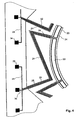
- Figure 7 illustrates the metal track 80 associated with flexible support 56e of Figure 5 .
- Each circuit of metal track 80 begins at a first bond-pad 82 on the external frame 58, runs along a first compliant leg 60a, across an eighth segment 84 of the ring structure 52 and back along the other compliant leg 60b to a second bond-pad 86 on the external frame 58. This circuit arrangement is repeated for each eighth segment 84 of the ring structure 52, such that each pair of compliant legs 60a and 60b only carries the metal track 80 associated with a single transducer.
- a separate third metal track 36 connected to ground is not required to minimise cross-coupling between metal tracks 24 running parallel to one another, wherein each metal track 24 is associated with a different drive or pick-off transducer. This is of particular importance where the metal track 24 associated with a primary drive transducer runs parallel to the metal track 24 associated with a secondary pick-off transducer along the same compliant leg 28 or 32.
- Routing the metal back 80 associated with different transducers along separate compliant legs 60a, 60b provides a reduction in the cross-coupling, ⁇ c , and hence in the cross-coupling bias error, ⁇ c , thus improving the overall rate bias temperature stability of the vibrating structure gyroscope 50.
- the compliant legs are symmetrically disposed about a line of symmetry LS and the portions of the metal track running from the respective compliant legs onto the ring structure 52 diverge from said line of symmetry to form a loop which is also substantially symmetrically disposed about said line of symmetry. This feature minimises disturbing motor forces acting on the compliant legs and maximises the gain of the transducer.
- a magnetic field is applied around the periphery of the ring structure 52, oriented perpendicular to the plane of the ring structure 52.
- the magnetic field is applied by a permanent magnet, located inside the circumference of the ring structure 52, and an upper pole piece and lower pole piece which are arranged to concentrate the magnetic field in a gap between the pole pieces in the vicinity of the periphery of the ring structure 52.
- the ring structure 52, compliant legs 60a, 60b and external frame 58 are bonded onto a supporting glass substrate. This assembly is in turn bonded onto a glass support structure together with the permanent magnet and pole pieces, which are assembled with the ring structure 52 located in the gap between the upper and lower pole piece.
- a metal track 80 is in motion within the magnetic field, a voltage will be generated across the metal track 80.
- a metal track 80 arranged in this manner will define a pick-off transducer.
- Such a MEMS gyroscope 52 will typically be operated in a closed loop mode of operation.
- the primary carrier mode is driven at the resonance maximum using a primary drive transducer controlled by a Phase Locked Loop.
- the amplitude of motion of the ring structure 52 is maintained at a constant value by an Automatic Gain Control loop, which is arranged to compare the amplitude of motion of the ring structure 52, as measured at the primary pick-off transducer, to a fixed reference level and to dynamically adjust a drive signal to a primary drive transducer to maintain a constant signal level and hence a constant amplitude of motion of the ring structure 52.
- the magnitude of the Coriolis force induced when the ring structure 52 is rotated about the axis 68 normal to the plane of the ring structure 52, and hence the scalefactor of the MEMS gyroscope 50 is directly proportional to the amplitude of the primary carrier mode motion.
- the Coriolis force will induce motion in the secondary response mode, which is detected by a secondary pick-off transducer.
- the secondary response mode motion is nulled by an appropriately controlled secondary drive transducer.
- the drive force required to maintain the null condition of the secondary response mode provides a direct representation of the rotation rate applied about the axis 68.
- a further advantage of the support arrangement 54 of the present invention is that there is sufficient area on each compliant leg 60a, 60b to fabricate a two turn metal track 80 circuit, that is a pair of laterally spaced parallel metal tracks 80, around one or more of the flexible supports 56a to 56h.
- a metal track 80 is provided on an upper surface of a ring structure 52, the external frame 58 and each compliant leg 60a, 60b over an insulating surface oxide layer, not illustrated.
- Figure 8 illustrates the metal track 80 associated with flexible support 56e of Figure 5 .
- Each circuit begins at the first bond-pad 82 on the external frame 58, runs along the first compliant leg 60a, across the eighth segment 84 of the ring structure 52 and back along the other compliant leg 60b, around the second bond-pad 86 on the external frame 58, back along the first complaint leg 60a, across the eighth segment 84 of the ring structure 52, along the other compliant leg 60b to the second bond-pad 86 on the external frame 58.
- the metal track 80 is arranged in a laterally spaced and parallel relation for each route about the complaint legs 60a, 60b and the eighth segment 84 of the ring structure 52. This circuit arrangement can be repeated for each eighth segment 84 of the ring structure 52, such that each pair of compliant legs 60a and 60b only carries the metal track 80 associated with a single transducer.
- Doubling the length of metal track 80 in the magnetic field i.e. increasing length L component in Equation 1 above, will increase the drive gain applied by a drive transducer by a factor of two. This enables the drive current required to achieve a given primary carrier mode amplitude to be reduced.
- the amount of drive coupling into the rate channel, and hence the cross-coupling bias, ⁇ C, will also be further reduced, which will benefit to the rate bias temperature stability.
- doubling the length of the metal track 80 in the magnetic field i.e. increasing the L component in Equation 2
- the noise level is dominated by the voltage noise of a secondary pick-off amplifier.
- doubling the pick-off transducer signal level will provide a two fold improvement in the rate equivalent signal to noise ratio of the vibrating structure gyroscope 50. Again, this provides additional performance enhancement for the vibrating structure gyroscope 50.
- the preferred embodiment of the present invention has an additional advantage over the prior art MEMS gyroscope 10.
- MEMS gyroscope 10 described in UK patent GB2322196
- a significant proportion of each compliant leg 14a to 14h is in close proximity to the ring structure 12 and hence to the region where the magnetic field intensity is at a maximum.
- the radial variation of the vertical component of the magnetic field, through the centre of the ring structure 12 and compliant legs 14a to 14h, is indicated as line 88.
- the radius of the magnetic field in millimetres (mm) is indicated along the abscissa and the vertical component of the magnetic field in milliTeslas (mT) is indicated along the ordinate.
- the magnetic field increases from the edge of the magnet, 2mm radius, and is at a maximum in the region of the gap, 3mm radius.
- the magnetic field reduces with increasing radius, greater than 3mm, but is still around ten percent of the peak value at a radius of 4mm. Accordingly, for the MEMS gyroscope of UK patent GB2322196 , a significant portion of each complaint leg 14a to 14h is located in a region of high magnetic field. When current is passed through the compliant legs 14a to 14h, significant forces will be generated in the plane of the ring structure 12, perpendicular to the path of the current flow.
- the symmetric pairs of compliant legs 60a, 60b are arranged such that the second radial sections 66 provide a greater separation for the first radial section 62 and arcuate section 64 from the gap of the magnetic field. Therefore, the amount of compliant leg 60a, 60b within the region of the magnetic field is reduced thus reducing the magnitude of the forces generated and the level of spurious signals induced in the metal track 80 associated with a pickoff transducer.
- the symmetric structure of the complaint legs 60a, 60b also ensures that the forces and signals generated on each complaint leg 60a, 60b of a given flexible support 56a to 56h will be substantially equal and opposite. Accordingly, such undesirable forces and signals will substantially cancel.
- the improved support arrangement 54 facilitates improvements to the quadrature bias temperature stability and hence the overall rate bias performance of the vibrating structure gyroscope 50.
- the improved support arrangement 54 further enables a metal track 80 circuit layout that reduces cross-coupling between the metal tracks 80 associated with drive and pick-off transducers, thereby enabling a further improvement to the rate bias temperature stability of the vibrating structure gyroscope 50.
- the improved support arrangement 54 can be implemented without substantial changes in the fabrication or assembly processes of the vibrating structure gyroscope 50, using the same permanent magnet, upper and lower pole pieces.
- the resulting vibrating structure gyroscope 50 can also incorporate the same control electronics, thus enabling improved quadrature bias temperature stability without an increase in unit cost of the vibrating structure gyroscope 50.
- the eight flexible supports can be arranged internal ly within the ring structure such that compliant legs are attached at one end to the internal periphery of the ring structure and at the other from a central hub of the substrate located internally of the ring structure.
- bond-on pads will be provided on the hub and the metal track is located on the hub, the compliant legs and the ring structure.
- the arrangement of the compliant legs and the track is otherwise similar to that described with reference to Figures 5 to 9 .
- the substrate that defines the external frame 58 can be sealed to form a sealed cavity encapsulating the ring structure 52, the flexible supports 56a to 56h and associated metal track 80, thereby inhibiting ingress of unwanted material within the sealed cavity.
Landscapes
- Physics & Mathematics (AREA)
- Engineering & Computer Science (AREA)
- General Physics & Mathematics (AREA)
- Radar, Positioning & Navigation (AREA)
- Remote Sensing (AREA)
- Gyroscopes (AREA)
Abstract
Description
- This invention relates to a vibrating structure gyroscope, which is particularly, but not exclusively, suitable for use as a Coriolis type gyroscope constructed using Micro-Electro-Mechanical Systems techniques.
- Coriolis type gyroscopes, fabricated using Micro-Electro-Mechanical Systems (MEMS) technology, are now widely used for a range of high volume applications. For example, in the automotive industry such gyroscopes can be utilised in advanced braking systems, active suspension, rollover detection and prevention applications and navigation applications. The performance requirements of gyroscopes for such applications are relatively undemanding, particularly when compared to typical aerospace and military applications, where gyroscopes are used for guidance and control.
- The suitability of MEMS gyroscopes for such applications is largely based on their low cost per unit, which is achieved primarily by the wafer level fabrication techniques of MEMS processing that enables MEMS gyroscopes to be economically produced in large quantities. The performance level of MEMS gyroscopes is relatively modest in comparison with other classes of gyroscope, such as spinning wheel or fibre optic gyroscopes. However, the use of higher specification gyroscopes is typically restricted to aerospace and military applications as the unit cost of such gyroscopes is too high to be considered for higher volume automotive and commercial applications. Conversely, the lower performance capability of MEMS gyroscopes prohibits their use in the majority of aerospace and military applications.
- UK patent
GB2322196 - Referring to
Figure 1 , a knownMEMS gyroscope 10, similar to that described in UK patentGB 2322196 silicon ring structure 12 that is externally supported by eightcompliant legs 14a to 14h. Theselegs 14a to 14h are in turn attached to a rigidexternal frame 16. Thegyroscope 10 is arranged to operate using a cos2θ vibration mode pair, as illustrated with referenced toFigure 2a and 2b . One of the vibration mode pair is excited as a primary carrier mode P,Figure 2a wherein the dotted line indicates the extremes of motion of thering structure 12 in the primary carrier mode P. When thering structure 12 is rotated around anaxis 18 normal to the plane of thering structure 12 Coriolis forces are generated, which couple energy into a secondary response mode S,Figure 2b wherein the dotted line indicates the extremes of motion of thering structure 12 in the secondary response mode S. The amplitude of the induced motion is directly proportional to the applied rotation rate about the axis normal to the plane of thering structure 12. - The primary carrier mode P is generated using at least one drive transducer and the secondary response mode S is detected using at least one pick-off transducer. The drive and pick-off transducers are arranged around the
ring structure 12. - Referring to
Figure 3 , in order to implement both drive and pick-off transducers, a metal track is provided on an upper surface of aring structure 20 and anexternal frame 22, over an insulating surface oxide layer. Referring toFigure 4 , wherein in like references have been used to indicate similar integers to those described with reference toFigure 3 ,metal track 24 is repeated for eight circuits, one circuit for each drive and pick-off transducer. Each circuit ofmetal track 24 begins at a first bond-pad 26, runs along a firstcompliant leg 28, across aneighth segment 30 of thering structure 20 and back along an adjacentcompliant leg 32 to a second bond-pad 34. This circuit arrangement is repeated for eacheighth segment 30 of thering structure 20, such that eachcompliant leg 28 carries ametal track 24 for two adjacent transducers. - A
third metal track 36 is located along the centre of eachcompliant leg metal track 24 associated with adjacent transducers to reduce the cross-coupling effect between circuits associated with adjacent transducers. - A magnetic field B is applied around the periphery of the
ring structure 20 and arranged perpendicular to the plane of thering structure 20. The magnetic field is applied by apermanent magnet 38, located inside the circumference of thering structure 20, and anupper pole piece 40 andlower pole piece 42 which are arranged to concentrate the magnetic field in a gap between thepole pieces ring structure 20. - The
ring structure 20,compliant legs external frame 22 are bonded onto a supportingglass substrate 44. This assembly is in turn bonded onto aglass support structure 46 together with thepermanent magnet 38 andpole pieces ring structure 20 located in the gap between the upper andlower pole piece - In operation, passing an alternating current through a
metal track 24 will generate a Lorentz force where themetal track 24 passes through the magnetic field. The magnitude of the force, Fl , will be given by:
where B is the magnetic field, I is the current and L is the length ofmetal track 24 in the magnetic field. If the frequency of the alternating current is at the resonance frequency of the primary carrier mode, thering structure 20 will be excited into resonant vibratory motion. Ametal track 24 arranged in this manner will define a drive transducer. - Where a
metal track 24 is in motion within the magnetic field, a voltage, V, will be generated across themetal track 24, which is given by:
where v is the peak velocity of the vibratory motion of themetal track 24 in the magnetic field, B is the magnetic field and L is the length ofmetal track 24 in the magnetic field. Ametal track 24 arranged in this manner will define a pick-off transducer. - Such a
MEMS gyroscope 10 will typically be operated in a closed loop mode of operation. In this mode, the primary carrier mode P is driven at the resonance maximum using a primary drive transducer controlled by a Phase Locked Loop. The amplitude of motion of thering structure 12 is maintained at a constant value by an Automatic Gain Control loop, which is arranged to compare the amplitude of motion of thering structure 12, as measured at a primary pick-off transducer, to a fixed reference level and to dynamically adjust a drive signal to the primary drive transducer to maintain a constant signal level and hence a constant amplitude of motion of thering structure 12. The magnitude of the Coriolis force induced when thering structure 12 is rotated about theaxis 18 normal to the plane of thering structure 12, and hence the scalefactor of theMEMS gyroscope 10 is directly proportional to the amplitude of the primary carrier mode P motion. The Coriolis force will induce motion in the secondary response mode S, which is detected by a secondary pick-off transducer. In the closed loop mode of operation, the secondary response mode S motion is nulled by an appropriately controlled secondary drive transducer. The drive force required to maintain the null condition of the secondary response mode S provides a direct representation of the rotation rate applied about theaxis 18. - Generally, there are a number of possible sources of rate bias error for a
MEMS gyroscope 10. The two most significant errors for aMEMS gyroscope 10 are known to be the quadrature bias error, which arises due to imperfections in the geometry of thering structure 12, and the cross-coupling error, which arises due to direct coupling of the primary drive signal into the secondary pick-off signal detected in a rate channel. - In an ideal case, wherein the electronic circuits are suitably phased and there are identical carrier and response mode frequencies for the
ring structure 12, there will be no motion detected at a secondary pick-off transducer when theMEMS gyrosdope 12 is not subject to rotation aboutaxis 18. However, in reality, small geometric imperfections of thering structure 12, arising during the fabrication process, will give rise to a small splitting of the primary carrier P and secondary response S mode frequencies. This frequency split also tends to fix the angular position of the primary carrier P and the secondary response S modes at an arbitrary angle, α, with respect to a primary drive transducer arranged at α=0°. Accordingly, if the arbitrary angle is not zero, α≠0°, a primary drive force applied by the primary drive transducer will excite both the primary carrier P and secondary response S modes to some extent. A phase locked loop circuit associated with the primary drive transducer will adjust the drive frequency to achieve a 90° phase shift between the primary carrier P and the secondary response S modes. However, motion will exist along the axis of the secondary response mode S that will be predominantly in quadrature phase with respect to the primary carrier mode P. In a closed loop system this motion will be nulled by a quadrature force component applied by the secondary drive transducer. - The quadrature drive level required to null the motion along the axis of the secondary response mode S is referred to as the quadrature bias, Ω QUAD , and is defined as:

where ΔF is the mode frequency split, α is the mode angle with respect to the primary drive axis and K is a constant including terms for the modal coupling coefficient and the secondary drive and primary pick-off gains. - Quadrature bias, Ω QUAD , can be large in comparison to the rate signals that the MEMS gyroscope is required to measure. A typical rate measurement range for a
MEMS gyroscope 10 used in an automotive application is ±100°/sec. The quadrature bias, ΩQUAD, if scaled in degrees per second, can be large, for example greater than ±100°/sec, in comparison to the rate signal and can vary significantly over the operating temperature range of theMEMS gyroscope 10. Where a phase error, Φ E , exists, a small proportion of this error signal will appear on the rate channel. This will give rise to a rate bias error, Ω Err , which is given by:
- Even a relatively small phase error, Φ E , can give rise to a significant rate bis error, Ω Err . Any variation in the quadrature signal or the phase error, Φ E , with temperature will cause the quadrature bias, Ω QUAD, to vary which will severely limit the accuracy and stability of the
MEMS gyroscope 10. The phase error, Φ E , will typically be relatively stable over the operating temperature range of theMEMS gyroscope 10. However, the quadrature bias, Ω QUAD , will typically vary by a significant amount. This large variation results in a correspondingly large variation in the quadrature bias error and hence an instability in the rate bias performance. - The dominant contribution to the cross-coupling of the primary drive signal into the secondary pick-off, and hence the rate channel, arises due to the close proximity of the
metal tracks 24 associated with adjacent transducers, which run parallel to one another along a singlecompliant leg third metal track 36 connected to ground is arranged between the twoparallel metal tracks 24 to minimise the direct capacitive coupling between themetal tracks 24. However, a significant electrical coupling still exists between the two metal tracks 24. The magnitude of the cross-coupling bias error, Ωc, arising from this coupling is defined as:
where Φc is the coupling coefficient, F is the resonance frequency, and Q is the Quality Factor of the resonance mode. This mechanism is known to contribute to rate bias, for example between 1 and 2 degrees per second of rate bias at ambient temperature. This value will scale as 1/Q2 and the Quality Factor, Q, will vary by a significant amount, i.e. ±50%, over the operating temperature range of theMEMS gyroscope 10. Therefore, this mechanism makes a significant contribution to the rate bias variation over temperature, which, due to its non-linear nature, is difficult to compensate. -
GB2322196A -
WO0120257A -
GB 2276976A - a substantially planar annular resonator;
- a substrate;
- at least one drive transducer arranged to cause the annular resonator to oscillate in a primary in-plane mode at the resonant frequency of the primary mode and having an associated flexible support including first and second leg members which have a radially-extending line of symmetry (LS) between them;
- a support arrangement including a plurality of flexible supports arranged to support the annular resonator from the substrate and to allow the annular resonator to oscillate in the primary in-plane mode and to oscillate in a secondary in-plane mode in response to an angular velocity applied around an axis substantially perpendicular to the plane of the annular resonator, and
- at least one pick-off transducer arranged to detect oscillation of the annular resonator in the secondary in-plane mode and having an associated flexible support including first and second leg members which have a radially-extending line of symmetry between them;
wherein a magnetic field is arranged perpendicular to the plane of the annular resonator such that the drive transducers are located within the magnetic field,
wherein said at least one drive transducer includes a metal track on the annular resonator and on the flexible supports, and has a continuous metal track comprising a first track section running from the substrate along the first leg member, along a section of the annular resonator and along the second leg member back to the substrate, said first and second leg members only carrying the metal track associated with a single drive transducer, - The present invention provides a vibrating structure gyroscope as in the above summary of
GB 2276976A - The above magnetic pick-off transducer has the advantage over the capacitive transducer utilised in
GB 2276976A - Preferably the continuous metal track further comprises at least a second track section continuing from the substrate along the first leg member, along a section of the annular resonator and along the second leg member back to the substrate, said track sections being connected in series and laterally spaced apart from each other.
- This feature enhances the driving oscillation and the pick-off sensitivity and hence increases the signal-to-noise ratio.
- Preferably each leg member includes a first radial section extending inwardly from said substrate, a circumferential section, and a second radial section arranged such that the first radial section and second radial section are connected to one another via the circumferential section, and the second radial section is connected to the external periphery of the annular resonator with said circumferential section located outside said magnetic field.
- This leg configuration is highly compliant and ensures that the current flowing through the circumferential section does not interfere with the motor or generator action of the current flowing through the track which runs along the section of the annular resonator. Furthermore the first radial sections, located outside the magnetic field, similarly do not cause any interference with the in-plane radial oscillation of the annular resonator and the effects of currents flowing in both the first and second radial sections, being antiparallel, tend to cancel each other.
- Preferably said second radial sections of the respective leg members are spaced apart with a spacing greater than the length of the second radial sections.
- This feature tends to maximise the length of the track portion which runs along the section of the annular resonator and which generates the desired motor action (in a drive transducer) or signal (in a pick-off transducer) in relation to the length of the radial sections and their associated conductor tracks, which do not.
- Preferably said first radial sections of said respective leg members are spaced apart with a spacing which is less than the length of said first radial sections.
- This feature tends to maximise the inductive cancellation of the currents running along the first radial sections.
- The flexible supports are preferably equiangularly spaced about the annular resonator.
- In a preferred embodiment at least one primary drive transducer is arranged to cause the annular resonator to oscillate in a primary mode at the resonant frequency of the primary mode, at least one primary pick-off transducer is arranged to detect oscillation of the annular resonator in the primary mode and to maintain the annular resonator at the resonant frequency of the primary mode, at least one secondary pick-off transducer is arranged to detect oscillation of a secondary mode induced when angular velocity is applied around the axis substantially perpendicular to the annular resonator and at least one secondary drive transducer is arranged to null the induced secondary mode oscillation.
- The annular resonator, substrate and support arrangement may be arranged substantially in the same plane as one another. The drive and pick-off transducers may be arranged substantially coplanar with one another and with the substrate.
- The leg members may optionally be supported at one end from a central hub of the substrate located internally of the annular resonator and each leg member connected at the other end to the internal periphery of the annular resonator. Alternatively, each leg member may be supported at one end from the substrate externally of the annular resonator and each leg member connected at the other end to the external periphery of the annular resonator.
- The substrate may be sealed to form a sealed cavity encapsulating the annular resonator, the support arrangement and the drive and pick-off transducers.
- The support arrangement, annular resonator and substrate may be formed from silicon and an insulating layer may be arranged between metal tracks and the support arrangement, annular resonator and substrate.
- Preferred embodiments of the invention will now be described, by way of example only, with reference to the accompanying drawings, in which:
-
Figure 1 illustrates, in schematic plan view, a MEMS gyroscope according to the prior art; -
Figure 2a schematically illustrates a ring structure according to the prior art and the action of radial displacement of a primary carrier mode P; -
Figure 2b schematically illustrates a ring structure according to the prior art and the action of radial displacement of a secondary response mode S; -
Figure 3 illustrates, in elevation sectional view, a MEMS gyroscope according to the prior art; -
Figure 4 illustrates, in partial plan view, a metal track arrangement according to the prior art; -
Figure 5 illustrates, in plan view, a vibrating structure gyroscope according to the present invention; -
Figure 6 illustrates, in graph form, a comparison of quadrature bias as a function of operating temperature of a MEMS gyroscope according to the prior art and a vibrating structure gyroscope according to the present invention; -
Figure 7 illustrates, in partial plan view, a metal track arrangement according to the present invention; -
Figure 8 illustrates, in partial plan view, an alternative metal track arrangement according to the present invention; -
Figure 9 illustrate, in graph form, radial variation in the vertical component of a magnetic field in an embodiment of the present invention, and -
Figure 10 is a block diagram illustrating the electronic signal processing arrangement of the embodiments ofFigures 5 ,7 and8 . - The inventor has appreciated that the variation in the quadrature bias for the prior
art MEMS gyroscope 10 described with reference toFigures 1 to 4 , is caused by variation in the frequency split of the primary carrier P and secondary response S mode frequencies and the position of the secondary response mode S over temperature. The differential expansion between the silicon of theexternal frame 22 and theglass support structure 46 tends to distort theexternal frame 22. This in turn distorts thecompliant legs 14a to 14h in such a way that the primary carrier P and secondary response S modes are differentially perturbed thus affecting their frequencies and mode alignment with respect to the ring structure orannular resonator 12. - Referring to
Figure 5 , a vibratingstructure gyroscope 50, includes a planarsilicon ring structure 52 that is externally supported by a support arrangement 54 having eightflexible supports 56a to 56h arranged to retain the ring structure within a substrate defining a rigidexternal frame 58. Eachflexible support 56a to 56h includes a pair ofcompliant legs ring structure 52 and at the other end to the internal periphery of theexternal frame 58. In this example, thecompliant legs compliant leg radial section 62, anarcuate section 64 and a secondradial section 66 arranged such that the firstradial section 62 and secondradial section 66 are connected to one another via thearcuate section 64, the firstradial section 62 is connected to the internal periphery of theexternal frame 58 and the secondradial section 66 is connected to the external periphery of thering structure 52. - The first and second radial sections provide compliance in the tangential direction (to ensure sensitivity to rotation about axis 68) and
arcuate section 64 provides compliance in the radial direction. The close spacing (preferably less than half their length) of the firstradial sections 62 ensures that the inductive effects of currents through their associated metal track portions (shown inFigure 7 ) are cancelled. - It will be understood that the
ring structure 52,external frame 58 and support arrangement 54 can all be formed from a single substrate of silicon material using MEMS manufacturing techniques. - In this manner, the effect of distortion of the
compliant legs ring structure 52 is reduced as the in-plane stiffness of thecompliant legs ring structure 52 to a greater degree from external stress and strain. This is achieved by reducing the width of thecompliant legs compliant legs compliant legs ring structure 52 in response to shock and vibration inputs applied along anaxis 68 normal to the plane of thering structure 52. This is beneficial as it reduces the sensitivity of the vibratingstructure gyroscope 50 to externally applied mechanical disturbances. - Accordingly, the support arrangement 54 illustrated in
Figure 5 has eightflexible supports 56a to 56h equiangularly spaced about thering structure 52, eachflexible support compliant legs Figures 1 to 4 . This provides enhanced isolation from thermally induced stress and strain and maintains the out of plane stiffness required to minimise sensitivity to shock and vibration. The in-plane stiffness of an individualcompliant leg compliant leg compliant leg compliant leg compliant legs 14a to 14h for the device described in UK patentGB2322196 compliant legs Figure 5 arrangement. The combined stiffness of the support arrangement 54 in response to in-plane displacement has been reduced by approximately a factor of four compared to the device described in UK patentGB2322196 GB2322196 - Referring to
Figure 10 , the primary loop comprises a pair of inductive pick off transducers (constituted by the metal track sections shown inFigure 7 orFigure 8 ) onlegs amplifier 118 to ademodulator 144 for automatic gain control and a phase detector PD (130) to set the frequency of oscillation of the ring by means of a VCO (voltage controlled oscillator) 134 after a loop filter F(s) (132) . A 90 degree phase shift is used for the reference for thephase detector 130. After passing through thegain control 148 and again stage 166, drive signals applied to primary drive transducers (constituted by the metal track sections shown inFigure 7 orFigure 8 onlegs ring 52 into primary motion. - The P phase is at 90 degrees with respect to the primary drive and is in phase with the primary pick off. The Q phase is in phase with the primary drive and 90 degrees out of phase with the primary pick off signal.
- Signals from secondary inductive pick off transducers (constituted by the metal tracks on
legs amplifier 120 and go via two demodulators 154 (in phase P) and 156 (quadrature phase Q) to loop filters G(s) 158 and 160 and thence to in phase and quadrature remodulators 162 and 164 respectively. These two signals are then joined to form the secondary drive going to drive transducers constituted by the metal tracks onlegs - The output rate signal from demodulator 126 uses the in-phase signal P component of the secondary drive.
- In use, the secondary drive transducers are arranged to null the secondary mode oscillation (S) induced when angular velocity is applied about the
sensitive axis 68. - Referring to
Figure 6 , the beneficial effect of enhanced in-plane mechanical isolation of thering structure 52 to thermally induced strains can be appreciated from a comparison the quadrature bias in degrees per second, indicated along theordinate 70, against temperature in degrees Celsius indicated along theabscissa 72, of the device of UK patentGB2322196 line 74, and the vibratingstructure gyroscope 50 according to the present invention, indicated asline 76.Line 74 illustrates a greater variation over temperature compared to theline 76. For example, the quadrature bias temperature stability of the present invention can exhibit an eight fold improvement over the prior art device of UK patentGB2322196 - In the
Figure 5 arrangement, a primary carrier mode is generated using at least one drive transducer and a secondary response mode is detected using at least one pick-off transducer. The drive and pick-off transducers are arranged around thering structure 52, in this case, there are eight transducers equiangularly spaced around thering structure 52. Four drive transducers, one pair of transducers arranged to provide a primary drive to thering structure 52 and one pair of transducers arranged to provide a secondary drive to the ring structure and four pick-off transducers, one pair of transducers arranged to provide a primary pick-off signal and one pair of transducers arranged to provide a secondary pick-off signal. - Referring to
Figure 7 , wherein like references have been used to indicate similar integers to those described with reference toFigure 5 , in order to implement both drive and pick-off transducers, ametal track 80 is provided on an upper surface of thering structure 52, theexternal frame 58 and eachcompliant leg metal track 80 is repeated for eight circuits, one circuit for each drive and pick-off transducer.Figure 7 illustrates themetal track 80 associated withflexible support 56e ofFigure 5 . Each circuit ofmetal track 80 begins at a first bond-pad 82 on theexternal frame 58, runs along a firstcompliant leg 60a, across aneighth segment 84 of thering structure 52 and back along the othercompliant leg 60b to a second bond-pad 86 on theexternal frame 58. This circuit arrangement is repeated for eacheighth segment 84 of thering structure 52, such that each pair ofcompliant legs metal track 80 associated with a single transducer. - Accordingly, as was the case in the prior art, a separate
third metal track 36 connected to ground is not required to minimise cross-coupling betweenmetal tracks 24 running parallel to one another, wherein eachmetal track 24 is associated with a different drive or pick-off transducer. This is of particular importance where themetal track 24 associated with a primary drive transducer runs parallel to themetal track 24 associated with a secondary pick-off transducer along the samecompliant leg - Routing the metal back 80 associated with different transducers along separate
compliant legs structure gyroscope 50. - The compliant legs are symmetrically disposed about a line of symmetry LS and the portions of the metal track running from the respective compliant legs onto the
ring structure 52 diverge from said line of symmetry to form a loop which is also substantially symmetrically disposed about said line of symmetry. This feature minimises disturbing motor forces acting on the compliant legs and maximises the gain of the transducer. - As with the prior art, a magnetic field is applied around the periphery of the
ring structure 52, oriented perpendicular to the plane of thering structure 52. The magnetic field is applied by a permanent magnet, located inside the circumference of thering structure 52, and an upper pole piece and lower pole piece which are arranged to concentrate the magnetic field in a gap between the pole pieces in the vicinity of the periphery of thering structure 52. - The
ring structure 52,compliant legs external frame 58 are bonded onto a supporting glass substrate. This assembly is in turn bonded onto a glass support structure together with the permanent magnet and pole pieces, which are assembled with thering structure 52 located in the gap between the upper and lower pole piece. - As previously described, passing an alternating current through the
metal track 80 will generate a Lorentz force where themetal track 80 passes through the magnetic field. If the frequency of the alternating current is at the resonance frequency of the primary carrier mode, thering structure 52 will be excited into resonant vibratory motionA metal track 80 arranged in this manner will define a drive transducer. - Where a
metal track 80 is in motion within the magnetic field, a voltage will be generated across themetal track 80. Ametal track 80 arranged in this manner will define a pick-off transducer. - Such a
MEMS gyroscope 52 will typically be operated in a closed loop mode of operation. In this mode, the primary carrier mode is driven at the resonance maximum using a primary drive transducer controlled by a Phase Locked Loop. The amplitude of motion of thering structure 52 is maintained at a constant value by an Automatic Gain Control loop, which is arranged to compare the amplitude of motion of thering structure 52, as measured at the primary pick-off transducer, to a fixed reference level and to dynamically adjust a drive signal to a primary drive transducer to maintain a constant signal level and hence a constant amplitude of motion of thering structure 52. The magnitude of the Coriolis force induced when thering structure 52 is rotated about theaxis 68 normal to the plane of thering structure 52, and hence the scalefactor of theMEMS gyroscope 50 is directly proportional to the amplitude of the primary carrier mode motion. The Coriolis force will induce motion in the secondary response mode, which is detected by a secondary pick-off transducer. In the closed loop mode of operation, the secondary response mode motion is nulled by an appropriately controlled secondary drive transducer. The drive force required to maintain the null condition of the secondary response mode provides a direct representation of the rotation rate applied about theaxis 68. - Referring to
Figure 8 , wherein like references have been used to indicate similar integers to those described with reference toFigures 5 and7 , a further advantage of the support arrangement 54 of the present invention is that there is sufficient area on eachcompliant leg turn metal track 80 circuit, that is a pair of laterally spacedparallel metal tracks 80, around one or more of theflexible supports 56a to 56h. In order to implement such a drive or pick-off transducer, ametal track 80 is provided on an upper surface of aring structure 52, theexternal frame 58 and eachcompliant leg Figure 8 illustrates themetal track 80 associated withflexible support 56e ofFigure 5 . Each circuit begins at the first bond-pad 82 on theexternal frame 58, runs along the firstcompliant leg 60a, across theeighth segment 84 of thering structure 52 and back along the othercompliant leg 60b, around the second bond-pad 86 on theexternal frame 58, back along thefirst complaint leg 60a, across theeighth segment 84 of thering structure 52, along the othercompliant leg 60b to the second bond-pad 86 on theexternal frame 58. It will be noted that themetal track 80 is arranged in a laterally spaced and parallel relation for each route about thecomplaint legs eighth segment 84 of thering structure 52. This circuit arrangement can be repeated for eacheighth segment 84 of thering structure 52, such that each pair ofcompliant legs metal track 80 associated with a single transducer. - This effectively doubles the length of the
metal track 80 within the magnetic field applied to thering structure 52. Accordingly, the gain of each drive and pick-off transducer is thereby also doubled. Such an arrangement would not be practical for the prior art apparatus due to the limitations on the geometry of themetal track 24 as imposed by the fabrication process. These limitations require a minimum separation betweenadjacent metal tracks 24 of more than five microns and a similar separation between the edge of themetal track 24 and the edge of thecomplaint leg - Doubling the length of
metal track 80 in the magnetic field, i.e. increasing length L component in Equation 1 above, will increase the drive gain applied by a drive transducer by a factor of two. This enables the drive current required to achieve a given primary carrier mode amplitude to be reduced. The amount of drive coupling into the rate channel, and hence the cross-coupling bias, ^C, will also be further reduced, which will benefit to the rate bias temperature stability. - Furthermore, doubling the length of the
metal track 80 in the magnetic field, i.e. increasing the L component inEquation 2, will also increase the signal provided at a pick-off transducer by a factor of two, for a given amplitude of motion. For such a vibratingstructure gyroscope 50, operating in a closed loop mode, the noise level is dominated by the voltage noise of a secondary pick-off amplifier. Accordingly, doubling the pick-off transducer signal level will provide a two fold improvement in the rate equivalent signal to noise ratio of the vibratingstructure gyroscope 50. Again, this provides additional performance enhancement for the vibratingstructure gyroscope 50. - The preferred embodiment of the present invention has an additional advantage over the prior
art MEMS gyroscope 10. In theMEMS gyroscope 10 described in UK patentGB2322196 compliant leg 14a to 14h is in close proximity to thering structure 12 and hence to the region where the magnetic field intensity is at a maximum. Referring toFigure 9 , the radial variation of the vertical component of the magnetic field, through the centre of thering structure 12 andcompliant legs 14a to 14h, is indicated asline 88. The radius of the magnetic field in millimetres (mm) is indicated along the abscissa and the vertical component of the magnetic field in milliTeslas (mT) is indicated along the ordinate. As will be observed, the magnetic field increases from the edge of the magnet, 2mm radius, and is at a maximum in the region of the gap, 3mm radius. The magnetic field reduces with increasing radius, greater than 3mm, but is still around ten percent of the peak value at a radius of 4mm. Accordingly, for the MEMS gyroscope of UK patentGB2322196 complaint leg 14a to 14h is located in a region of high magnetic field. When current is passed through thecompliant legs 14a to 14h, significant forces will be generated in the plane of thering structure 12, perpendicular to the path of the current flow. These forces are undesirable as they will excite motion of thering structure 12 by exerting a force at the point of attachment of acompliant leg 14a to 14h. These forces are not aligned to the forces generated on thering structure 12 and tend to rotate the net resultant drive force applied by a drive transducer away from the desired alignment. These forces also tend to oppose the drive force applied by a drive transducer to thering structure 12 resulting in a reduction of the drive efficiency. The motion of thecompliant legs 14a to 14h supportingmetal tracks 24 associated with pick-off transducers is also problematic, as this will induce signals that interfere with the desired signals generated by the motion of thering structure 12 and thus degrade the accuracy of theMEMS gyroscope 10. - In the present invention, the symmetric pairs of
compliant legs radial sections 66 provide a greater separation for the firstradial section 62 andarcuate section 64 from the gap of the magnetic field. Therefore, the amount ofcompliant leg metal track 80 associated with a pickoff transducer. The symmetric structure of thecomplaint legs complaint leg flexible support 56a to 56h will be substantially equal and opposite. Accordingly, such undesirable forces and signals will substantially cancel. - Accordingly, the improved support arrangement 54 facilitates improvements to the quadrature bias temperature stability and hence the overall rate bias performance of the vibrating
structure gyroscope 50. The improved support arrangement 54 further enables ametal track 80 circuit layout that reduces cross-coupling between the metal tracks 80 associated with drive and pick-off transducers, thereby enabling a further improvement to the rate bias temperature stability of the vibratingstructure gyroscope 50. The improved support arrangement 54 can be implemented without substantial changes in the fabrication or assembly processes of the vibratingstructure gyroscope 50, using the same permanent magnet, upper and lower pole pieces. The resulting vibratingstructure gyroscope 50 can also incorporate the same control electronics, thus enabling improved quadrature bias temperature stability without an increase in unit cost of the vibratingstructure gyroscope 50. - It will be understood that other configurations of the flexible supports are possible. For example, the eight flexible supports can be arranged internal ly within the ring structure such that compliant legs are attached at one end to the internal periphery of the ring structure and at the other from a central hub of the substrate located internally of the ring structure. In this embodiment, bond-on pads will be provided on the hub and the metal track is located on the hub, the compliant legs and the ring structure. The arrangement of the compliant legs and the track is otherwise similar to that described with reference to
Figures 5 to 9 . - Furthermore, the substrate that defines the
external frame 58 can be sealed to form a sealed cavity encapsulating thering structure 52, theflexible supports 56a to 56h and associatedmetal track 80, thereby inhibiting ingress of unwanted material within the sealed cavity.
Claims (14)
- A vibrating structure gyroscope (50), including:a substantially planar annular resonator (52);a substrate (58);at least one drive transducer arranged to cause the annular resonator to oscillate in a primary in-plane mode at the resonant frequency of the primary mode and having an associated flexible support including first and second leg members (60a, 60b) which have a radially-extending line of symmetry (LS) between thema support arrangement (54) including a plurality of flexible supports (56a - 56h) arranged to support the annular resonator from the substrate and to allow the annular resonator to oscillate in the primary in-plane mode (P) and to oscillate in a secondary in-plane mode (S) in response to an angular velocity applied around an axis (68) substantially perpendicular to the plane of the annular resonator, andat least one pick-off transducer arranged to detect oscillation of the annular resonator in the secondary in-plane mode and having an associated flexible support including first and second leg members (60a, 60b) which have a radially-extending line of symmetry (LS) between them;
wherein a magnetic field (B) is arranged perpendicular to the plane of the annular resonator (52) such that the drive transducers are located within the magnetic field;
wherein said at least one drive transducer includes a metal track (80) on the annular resonator and on the flexible supports, and has a continuous metal track comprising a first track section running from the substrate along the first leg member (60a), along a section of the annular resonator (52) and along the second leg member (60b) back to the substrate, said first and second leg members only carrying the metal track (80) associated with a single drive transducer,
characterised in that said at least one pick-off transducer is located in said magnetic field and has a continuous metal track comprising a first track section running from the substrate along the first leg member (60a), along a section (84) of the annular resonator (52) and along the second leg member (60b) back to the substrate (58), said first and second leg members (60a, 60b) only carrying the metal track (80) associated with a single pick-off transducer. - A vibrating structure gyroscope (50) as claimed in Claim 1, wherein the continuous metal track (80) further comprises at least a second track section continuing from the substrate (58) along the first leg member (60a), along a section of the annular resonator (52) and along the second leg member (60b) back to the substrate, said track sections being connected in series and laterally spaced apart from each other.
- A vibrating structure gyroscope (50) as claimed in claim 1 or claim 2 wherein each leg member (60a, 60b) includes a first radial section (62) extending inwardly from said substrate (58), a circumferential section (64) and a second radial section (66) arranged such that the first radial section (62 )and second radial section (66) are connected to one another via the circumferential section (64), and the second radial section (66) is connected to the external periphery of the annular resonator (52) with said circumferential section (64) located outside said magnetic field (B).
- A vibrating structure gyroscope (50) as claimed in claim 3 wherein said second radial sections (66) of the respective leg members (60a, 60b) are spaced apart with a spacing greater than the length of the second radial sections.
- A vibrating structure gyroscope (50) as claimed in claim 3 or claim 4 wherein said first radial sections (62) of said respective leg members (60a, 60b) are spaced apart with a spacing which is less than the length of said first radial sections.
- A vibrating structure gyroscope (50), as claimed in any preceding claim, wherein a ring pole magnetic arrangement (20) is arranged to concentrate the magnetic field (B) on said annular resonator (52).
- A vibrating structure gyroscope (50), as claimed in any preceding claim, wherein said flexible supports (56a - 56h) are equiangularly spaced about said annular resonator (52).
- A vibrating structure gyroscope (50), as claimed in any preceding claim, wherein at least one secondary drive transducer is arranged to null the secondary mode oscillation (S) induced when angular velocity is applied about said axis (68).
- A vibrating structure gyroscope (50), as claimed in any preceding claim, wherein the annular resonator (52), substrate (58) and support arrangement (54) are substantially coplanar.
- A vibrating structure gyroscope (50), as claimed in any preceding claim, wherein the drive and pick-off transducers are substantially coplanar with one another and with the substrate (58).
- A vibrating structure gyroscope (50), as claimed in any of Claims 1 to 10, wherein the leg members (60a, 60b) are radially compliant legs, each leg member being connected at one end to the substrate (58) and supporting the annular resonator (52) at the other end.
- A vibrating struture gyroscope (50) as claimed in claim 11 wherein the annular resonator (52) is disposed within the substrate (58) and each leg member (60a, 60b) extends radially inwardly to the external periphery of the annular resonator from said one end to said other end.
- A vibrating structure gyroscope (50), as claimed in any preceding claim, wherein the substrate (58) is sealed to form a sealed cavity encapsulating the annular resonator (52), the support arrangement (54) and the drive and pick-off transducers.
- A vibrating structure gyroscope (50), as claimed in any preceding claim, wherein the support arrangement (54), annular resonator (52) and substrate (58) are formed from silicon.
Applications Claiming Priority (2)
| Application Number | Priority Date | Filing Date | Title |
|---|---|---|---|
| GBGB0812788.8A GB0812788D0 (en) | 2008-07-12 | 2008-07-12 | Improvements in or relating to vibrating structure gyroscopes |
| PCT/GB2009/050824 WO2010007406A2 (en) | 2008-07-12 | 2009-07-10 | Improvements in or relating to vibrating structure gyroscopes |
Publications (2)
| Publication Number | Publication Date |
|---|---|
| EP2324325A2 EP2324325A2 (en) | 2011-05-25 |
| EP2324325B1 true EP2324325B1 (en) | 2012-01-18 |
Family
ID=39722195
Family Applications (1)
| Application Number | Title | Priority Date | Filing Date |
|---|---|---|---|
| EP09785302A Active EP2324325B1 (en) | 2008-07-12 | 2009-07-10 | Improvements in or relating to vibrating structure gyroscopes |
Country Status (9)
| Country | Link |
|---|---|
| US (1) | US8555717B2 (en) |
| EP (1) | EP2324325B1 (en) |
| JP (1) | JP5410518B2 (en) |
| KR (1) | KR101613568B1 (en) |
| CN (1) | CN102089620B (en) |
| AT (1) | ATE542110T1 (en) |
| GB (1) | GB0812788D0 (en) |
| NO (1) | NO20110051A1 (en) |
| WO (1) | WO2010007406A2 (en) |
Families Citing this family (28)
| Publication number | Priority date | Publication date | Assignee | Title |
|---|---|---|---|---|
| RU2423667C1 (en) * | 2010-05-11 | 2011-07-10 | Открытое акционерное общество "Раменское приборостроительное конструкторское бюро" (ОАО "РПКБ") | Detecting element of vibration gyroscope |
| GB201200128D0 (en) * | 2012-01-05 | 2012-02-15 | Atlantic Inertial Systems Ltd | Strain decoupled sensor |
| DE102014105205B4 (en) * | 2013-04-26 | 2026-05-07 | Maxim Integrated Products, Inc. | Gyroscope shock and disturbance measurement circuit |
| GB201307773D0 (en) | 2013-04-30 | 2013-06-12 | Atlantic Inertial Systems Ltd | MEMS sensors |
| US9410806B2 (en) * | 2013-08-26 | 2016-08-09 | Robert Bosch Gmbh | System and method for gyroscope zero-rate-offset drift reduction through demodulation phase error correction |
| FI126070B (en) | 2014-01-28 | 2016-06-15 | Murata Manufacturing Co | Improved ring gyroscope structure and gyroscope |
| CN105486298A (en) * | 2015-11-27 | 2016-04-13 | 上海新跃仪表厂 | MEMS diamond multi-ring gyroscope and processing method thereof |
| US12265359B2 (en) * | 2016-07-06 | 2025-04-01 | Ecole Polytechnique Federale De Lausanne (Epfl) | General 2 degree of freedom isotropic harmonic oscillator and associated time base without escapement or with simplified escapement |
| GB2560334A (en) * | 2017-03-07 | 2018-09-12 | Atlantic Inertial Systems Ltd | Gyroscope in-field prognostics |
| GB2565298B (en) * | 2017-08-07 | 2022-03-16 | Atlantic Inertial Systems Ltd | Angular rate sensors |
| US10655964B2 (en) * | 2017-08-08 | 2020-05-19 | Hrl Laboratories, Llc | High quality factor MEMS silicon flower-of-life vibratory gyroscope |
| JP7258760B2 (en) * | 2017-09-21 | 2023-04-17 | 住友精密工業株式会社 | Angular rate sensor |
| GB2570732B (en) | 2018-02-06 | 2023-01-11 | Atlantic Inertial Systems Ltd | Angular rate sensors |
| GB2580116B (en) * | 2018-12-21 | 2023-07-19 | Atlantic Inertial Systems Ltd | Gyroscope |
| CN109900262B (en) * | 2019-04-08 | 2021-08-10 | 瑞声科技(新加坡)有限公司 | Gyroscope |
| CN110058041A (en) * | 2019-04-08 | 2019-07-26 | 瑞声科技(新加坡)有限公司 | Gyroscope |
| CN110044346A (en) * | 2019-04-08 | 2019-07-23 | 瑞声科技(新加坡)有限公司 | Gyroscope |
| US11121661B2 (en) * | 2019-06-20 | 2021-09-14 | Cirrus Logic, Inc. | Minimizing transducer settling time |
| GB201911534D0 (en) * | 2019-08-12 | 2019-09-25 | Atlantic Inertial Systems Ltd | Improved noise performance for vibrating structure gyroscopes |
| CN114096802B (en) * | 2020-05-15 | 2024-03-01 | 深圳市汇顶科技股份有限公司 | A kind of gyroscope and inertial sensor |
| US12287202B2 (en) | 2020-07-03 | 2025-04-29 | Sumitomo Precision Products Co., Ltd. | Vibrating-type gyroscope element and angular velocity sensor comprising same |
| CN115917249A (en) | 2020-07-03 | 2023-04-04 | 住友精密工业株式会社 | Vibration type gyro element and angular velocity sensor including the vibration type gyro element |
| EP3985352B1 (en) * | 2020-10-16 | 2023-12-27 | Atlantic Inertial Systems Limited | Gyroscope |
| EP3985351A1 (en) * | 2020-10-16 | 2022-04-20 | Atlantic Inertial Systems Limited | Quadrature bias error reduction for vibrating structure gyroscopes |
| EP4140941B1 (en) | 2021-08-24 | 2025-10-22 | Atlantic Inertial Systems Limited | Fabrication of mems structures from fused silica for inertial sensors |
| WO2023079849A1 (en) * | 2021-11-05 | 2023-05-11 | 住友精密工業株式会社 | Vibration type gyroscope, and angular velocity sensor provided with same |
| CA3253130A1 (en) * | 2022-03-11 | 2025-07-08 | Sumitomo Precision Products Co., Ltd. | Vibrating gyro element and gyroscope |
| CN116124111A (en) * | 2023-04-13 | 2023-05-16 | 中国人民解放军国防科技大学 | An electromagnetic fused silica ring micro-gyroscope and its preparation method |
Family Cites Families (14)
| Publication number | Priority date | Publication date | Assignee | Title |
|---|---|---|---|---|
| DE69102590T2 (en) | 1990-05-18 | 1994-10-06 | British Aerospace | Inertial sensors. |
| GB2276976B (en) * | 1993-04-07 | 1996-10-23 | British Aerospace | Method of manufacturing a motion sensor |
| GB2322196B (en) | 1997-02-18 | 2000-10-18 | British Aerospace | A vibrating structure gyroscope |
| GB9819821D0 (en) | 1998-09-12 | 1998-11-04 | Secr Defence | Improvements relating to micro-machining |
| US6272925B1 (en) | 1999-09-16 | 2001-08-14 | William S. Watson | High Q angular rate sensing gyroscope |
| JP3643116B2 (en) | 2002-06-28 | 2005-04-27 | 住友精密工業株式会社 | Conductive film for movable electric circuit and vibratory gyro |
| GB0227084D0 (en) | 2002-11-20 | 2002-12-24 | Bae Systems Plc | Method and apparatus for measuring scalefactor variation in a vibrating structure gyroscope |
| FR2856789B1 (en) * | 2003-06-27 | 2005-08-26 | Thales Sa | GYROMETER WITH VIBRANT MASS |
| WO2005075939A1 (en) | 2004-02-04 | 2005-08-18 | Bae Systems Plc | Method for reducing bias error in a vibrating structure gyroscope |
| TWI245902B (en) | 2004-05-14 | 2005-12-21 | Chung Shan Inst Of Science | Microstructure angular velocity sensor device |
| JP2006064539A (en) | 2004-08-26 | 2006-03-09 | Matsushita Electric Works Ltd | Gyroscope sensor and method for detecting angular speed |
| JP5036218B2 (en) * | 2006-05-29 | 2012-09-26 | 住友精密工業株式会社 | Angular velocity sensor |
| IL181367A (en) * | 2007-02-15 | 2013-03-24 | Elbit Systems Electro Optics Elop Ltd | Vibratory gyroscopic device for determining angular velocity |
| US7992438B2 (en) * | 2007-11-28 | 2011-08-09 | Chung Shan Institute Of Science And Technology, Armaments Bureau, M.N.D. | Multiaxial gyroscope |
-
2008
- 2008-07-12 GB GBGB0812788.8A patent/GB0812788D0/en not_active Ceased
-
2009
- 2009-07-10 WO PCT/GB2009/050824 patent/WO2010007406A2/en not_active Ceased
- 2009-07-10 US US13/003,468 patent/US8555717B2/en active Active
- 2009-07-10 CN CN200980127065.XA patent/CN102089620B/en active Active
- 2009-07-10 EP EP09785302A patent/EP2324325B1/en active Active
- 2009-07-10 KR KR1020117001271A patent/KR101613568B1/en active Active
- 2009-07-10 AT AT09785302T patent/ATE542110T1/en active
- 2009-07-10 JP JP2011517244A patent/JP5410518B2/en active Active
-
2011
- 2011-01-12 NO NO20110051A patent/NO20110051A1/en not_active Application Discontinuation
Also Published As
| Publication number | Publication date |
|---|---|
| CN102089620A (en) | 2011-06-08 |
| CN102089620B (en) | 2014-01-08 |
| GB0812788D0 (en) | 2008-08-20 |
| WO2010007406A2 (en) | 2010-01-21 |
| US20110167911A1 (en) | 2011-07-14 |
| KR101613568B1 (en) | 2016-04-19 |
| KR20110028510A (en) | 2011-03-18 |
| ATE542110T1 (en) | 2012-02-15 |
| NO20110051A1 (en) | 2011-04-12 |
| JP5410518B2 (en) | 2014-02-05 |
| US8555717B2 (en) | 2013-10-15 |
| WO2010007406A3 (en) | 2010-10-14 |
| JP2011528103A (en) | 2011-11-10 |
| EP2324325A2 (en) | 2011-05-25 |
Similar Documents
| Publication | Publication Date | Title |
|---|---|---|
| US8555717B2 (en) | Vibrating structure gyroscopes | |
| US7958781B2 (en) | Vibrating structure gyroscope | |
| US8087295B2 (en) | Dual-axis resonator gyroscope | |
| US5226321A (en) | Vibrating planar gyro | |
| US5889208A (en) | Angular velocity sensor having cantilever beams | |
| EP2577324B1 (en) | Mems inertial sensor and method of inertial sensing | |
| JP2872213B2 (en) | Vibration structure gyroscope | |
| KR20070032936A (en) | Resonant magnetometer device | |
| KR20020064378A (en) | Accelerometer | |
| JP6278604B2 (en) | Vibration gyro with bias correction function | |
| US10018686B1 (en) | Ultra-low noise sensor for magnetic fields | |
| JP2015072277A (en) | MEMS gyroscope with reduced magnetic sensitivity | |
| JP2013096801A (en) | Vibrating structure gyroscope with excellent output stability | |
| US10866098B2 (en) | Angular rate sensor arranged to determine amplitude of motion of secondary mode of vibration at resonant frequency | |
| CN111670338B (en) | Angle sensor with Coriolis vibrating gyroscope resonator | |
| US10928199B2 (en) | Angular rate sensors having supporting structures which comprise one passive supporting structure | |
| US20040118204A1 (en) | Vibratory gyroscopic rate sensor | |
| US12507595B2 (en) | Quadrature bias error reduction for vibrating structure gyroscopes | |
| EP2163848A1 (en) | Improvements in or relating to vibrating structure gyroscopes | |
| CN101558284B (en) | Improvements in or relating to a gyroscope | |
| CN121311736A (en) | Inertial angle sensor of electromechanical microsystem with micromachining | |
| EP1944574A1 (en) | Improvements in or relating to a gyroscope | |
| JP2017150997A (en) | Vibration gyro with reduced bias |
Legal Events
| Date | Code | Title | Description |
|---|---|---|---|
| PUAI | Public reference made under article 153(3) epc to a published international application that has entered the european phase |
Free format text: ORIGINAL CODE: 0009012 |
|
| 17P | Request for examination filed |
Effective date: 20110210 |
|
| AK | Designated contracting states |
Kind code of ref document: A2 Designated state(s): AT BE BG CH CY CZ DE DK EE ES FI FR GB GR HR HU IE IS IT LI LT LU LV MC MK MT NL NO PL PT RO SE SI SK SM TR |
|
| AX | Request for extension of the european patent |
Extension state: AL BA RS |
|
| GRAP | Despatch of communication of intention to grant a patent |
Free format text: ORIGINAL CODE: EPIDOSNIGR1 |
|
| GRAC | Information related to communication of intention to grant a patent modified |
Free format text: ORIGINAL CODE: EPIDOSCIGR1 |
|
| DAX | Request for extension of the european patent (deleted) | ||
| GRAS | Grant fee paid |
Free format text: ORIGINAL CODE: EPIDOSNIGR3 |
|
| GRAA | (expected) grant |
Free format text: ORIGINAL CODE: 0009210 |
|
| AK | Designated contracting states |
Kind code of ref document: B1 Designated state(s): AT BE BG CH CY CZ DE DK EE ES FI FR GB GR HR HU IE IS IT LI LT LU LV MC MK MT NL NO PL PT RO SE SI SK SM TR |
|
| REG | Reference to a national code |
Ref country code: GB Ref legal event code: FG4D |
|
| REG | Reference to a national code |
Ref country code: CH Ref legal event code: EP |
|
| REG | Reference to a national code |
Ref country code: AT Ref legal event code: REF Ref document number: 542110 Country of ref document: AT Kind code of ref document: T Effective date: 20120215 Ref country code: IE Ref legal event code: FG4D |
|
| REG | Reference to a national code |
Ref country code: DE Ref legal event code: R096 Ref document number: 602009004815 Country of ref document: DE Effective date: 20120315 |
|
| REG | Reference to a national code |
Ref country code: NL Ref legal event code: VDEP Effective date: 20120118 |
|
| REG | Reference to a national code |
Ref country code: NO Ref legal event code: T2 Effective date: 20120118 |
|
| LTIE | Lt: invalidation of european patent or patent extension |
Effective date: 20120118 |
|
| PG25 | Lapsed in a contracting state [announced via postgrant information from national office to epo] |
Ref country code: LT Free format text: LAPSE BECAUSE OF FAILURE TO SUBMIT A TRANSLATION OF THE DESCRIPTION OR TO PAY THE FEE WITHIN THE PRESCRIBED TIME-LIMIT Effective date: 20120118 Ref country code: NL Free format text: LAPSE BECAUSE OF FAILURE TO SUBMIT A TRANSLATION OF THE DESCRIPTION OR TO PAY THE FEE WITHIN THE PRESCRIBED TIME-LIMIT Effective date: 20120118 Ref country code: IS Free format text: LAPSE BECAUSE OF FAILURE TO SUBMIT A TRANSLATION OF THE DESCRIPTION OR TO PAY THE FEE WITHIN THE PRESCRIBED TIME-LIMIT Effective date: 20120518 Ref country code: HR Free format text: LAPSE BECAUSE OF FAILURE TO SUBMIT A TRANSLATION OF THE DESCRIPTION OR TO PAY THE FEE WITHIN THE PRESCRIBED TIME-LIMIT Effective date: 20120118 Ref country code: BE Free format text: LAPSE BECAUSE OF FAILURE TO SUBMIT A TRANSLATION OF THE DESCRIPTION OR TO PAY THE FEE WITHIN THE PRESCRIBED TIME-LIMIT Effective date: 20120118 Ref country code: BG Free format text: LAPSE BECAUSE OF FAILURE TO SUBMIT A TRANSLATION OF THE DESCRIPTION OR TO PAY THE FEE WITHIN THE PRESCRIBED TIME-LIMIT Effective date: 20120418 |
|
| PG25 | Lapsed in a contracting state [announced via postgrant information from national office to epo] |
Ref country code: LV Free format text: LAPSE BECAUSE OF FAILURE TO SUBMIT A TRANSLATION OF THE DESCRIPTION OR TO PAY THE FEE WITHIN THE PRESCRIBED TIME-LIMIT Effective date: 20120118 Ref country code: PL Free format text: LAPSE BECAUSE OF FAILURE TO SUBMIT A TRANSLATION OF THE DESCRIPTION OR TO PAY THE FEE WITHIN THE PRESCRIBED TIME-LIMIT Effective date: 20120118 Ref country code: FI Free format text: LAPSE BECAUSE OF FAILURE TO SUBMIT A TRANSLATION OF THE DESCRIPTION OR TO PAY THE FEE WITHIN THE PRESCRIBED TIME-LIMIT Effective date: 20120118 Ref country code: PT Free format text: LAPSE BECAUSE OF FAILURE TO SUBMIT A TRANSLATION OF THE DESCRIPTION OR TO PAY THE FEE WITHIN THE PRESCRIBED TIME-LIMIT Effective date: 20120518 Ref country code: GR Free format text: LAPSE BECAUSE OF FAILURE TO SUBMIT A TRANSLATION OF THE DESCRIPTION OR TO PAY THE FEE WITHIN THE PRESCRIBED TIME-LIMIT Effective date: 20120419 |
|
| REG | Reference to a national code |
Ref country code: AT Ref legal event code: MK05 Ref document number: 542110 Country of ref document: AT Kind code of ref document: T Effective date: 20120118 |
|
| PG25 | Lapsed in a contracting state [announced via postgrant information from national office to epo] |
Ref country code: CY Free format text: LAPSE BECAUSE OF FAILURE TO SUBMIT A TRANSLATION OF THE DESCRIPTION OR TO PAY THE FEE WITHIN THE PRESCRIBED TIME-LIMIT Effective date: 20120118 |
|
| PG25 | Lapsed in a contracting state [announced via postgrant information from national office to epo] |
Ref country code: RO Free format text: LAPSE BECAUSE OF FAILURE TO SUBMIT A TRANSLATION OF THE DESCRIPTION OR TO PAY THE FEE WITHIN THE PRESCRIBED TIME-LIMIT Effective date: 20120118 Ref country code: DK Free format text: LAPSE BECAUSE OF FAILURE TO SUBMIT A TRANSLATION OF THE DESCRIPTION OR TO PAY THE FEE WITHIN THE PRESCRIBED TIME-LIMIT Effective date: 20120118 Ref country code: EE Free format text: LAPSE BECAUSE OF FAILURE TO SUBMIT A TRANSLATION OF THE DESCRIPTION OR TO PAY THE FEE WITHIN THE PRESCRIBED TIME-LIMIT Effective date: 20120118 Ref country code: SI Free format text: LAPSE BECAUSE OF FAILURE TO SUBMIT A TRANSLATION OF THE DESCRIPTION OR TO PAY THE FEE WITHIN THE PRESCRIBED TIME-LIMIT Effective date: 20120118 Ref country code: SE Free format text: LAPSE BECAUSE OF FAILURE TO SUBMIT A TRANSLATION OF THE DESCRIPTION OR TO PAY THE FEE WITHIN THE PRESCRIBED TIME-LIMIT Effective date: 20120118 Ref country code: CZ Free format text: LAPSE BECAUSE OF FAILURE TO SUBMIT A TRANSLATION OF THE DESCRIPTION OR TO PAY THE FEE WITHIN THE PRESCRIBED TIME-LIMIT Effective date: 20120118 |
|
| PLBE | No opposition filed within time limit |
Free format text: ORIGINAL CODE: 0009261 |
|
| STAA | Information on the status of an ep patent application or granted ep patent |
Free format text: STATUS: NO OPPOSITION FILED WITHIN TIME LIMIT |
|
| PG25 | Lapsed in a contracting state [announced via postgrant information from national office to epo] |
Ref country code: SK Free format text: LAPSE BECAUSE OF FAILURE TO SUBMIT A TRANSLATION OF THE DESCRIPTION OR TO PAY THE FEE WITHIN THE PRESCRIBED TIME-LIMIT Effective date: 20120118 |
|
| 26N | No opposition filed |
Effective date: 20121019 |
|
| PG25 | Lapsed in a contracting state [announced via postgrant information from national office to epo] |
Ref country code: AT Free format text: LAPSE BECAUSE OF FAILURE TO SUBMIT A TRANSLATION OF THE DESCRIPTION OR TO PAY THE FEE WITHIN THE PRESCRIBED TIME-LIMIT Effective date: 20120118 |
|
| REG | Reference to a national code |
Ref country code: DE Ref legal event code: R097 Ref document number: 602009004815 Country of ref document: DE Effective date: 20121019 |
|
| PG25 | Lapsed in a contracting state [announced via postgrant information from national office to epo] |
Ref country code: MC Free format text: LAPSE BECAUSE OF NON-PAYMENT OF DUE FEES Effective date: 20120731 Ref country code: MK Free format text: LAPSE BECAUSE OF FAILURE TO SUBMIT A TRANSLATION OF THE DESCRIPTION OR TO PAY THE FEE WITHIN THE PRESCRIBED TIME-LIMIT Effective date: 20120118 |
|
| PG25 | Lapsed in a contracting state [announced via postgrant information from national office to epo] |
Ref country code: ES Free format text: LAPSE BECAUSE OF FAILURE TO SUBMIT A TRANSLATION OF THE DESCRIPTION OR TO PAY THE FEE WITHIN THE PRESCRIBED TIME-LIMIT Effective date: 20120429 |
|
| REG | Reference to a national code |
Ref country code: IE Ref legal event code: MM4A |
|
| PG25 | Lapsed in a contracting state [announced via postgrant information from national office to epo] |
Ref country code: MT Free format text: LAPSE BECAUSE OF FAILURE TO SUBMIT A TRANSLATION OF THE DESCRIPTION OR TO PAY THE FEE WITHIN THE PRESCRIBED TIME-LIMIT Effective date: 20120118 Ref country code: IE Free format text: LAPSE BECAUSE OF NON-PAYMENT OF DUE FEES Effective date: 20120710 |
|
| PGFP | Annual fee paid to national office [announced via postgrant information from national office to epo] |
Ref country code: IT Payment date: 20130719 Year of fee payment: 5 |
|
| REG | Reference to a national code |
Ref country code: CH Ref legal event code: PL |
|
| PG25 | Lapsed in a contracting state [announced via postgrant information from national office to epo] |
Ref country code: TR Free format text: LAPSE BECAUSE OF FAILURE TO SUBMIT A TRANSLATION OF THE DESCRIPTION OR TO PAY THE FEE WITHIN THE PRESCRIBED TIME-LIMIT Effective date: 20120118 Ref country code: LI Free format text: LAPSE BECAUSE OF NON-PAYMENT OF DUE FEES Effective date: 20130731 Ref country code: CH Free format text: LAPSE BECAUSE OF NON-PAYMENT OF DUE FEES Effective date: 20130731 |
|
| PG25 | Lapsed in a contracting state [announced via postgrant information from national office to epo] |
Ref country code: SM Free format text: LAPSE BECAUSE OF FAILURE TO SUBMIT A TRANSLATION OF THE DESCRIPTION OR TO PAY THE FEE WITHIN THE PRESCRIBED TIME-LIMIT Effective date: 20120118 Ref country code: LU Free format text: LAPSE BECAUSE OF NON-PAYMENT OF DUE FEES Effective date: 20120710 |
|
| PG25 | Lapsed in a contracting state [announced via postgrant information from national office to epo] |
Ref country code: HU Free format text: LAPSE BECAUSE OF FAILURE TO SUBMIT A TRANSLATION OF THE DESCRIPTION OR TO PAY THE FEE WITHIN THE PRESCRIBED TIME-LIMIT Effective date: 20090710 |
|
| PG25 | Lapsed in a contracting state [announced via postgrant information from national office to epo] |
Ref country code: IT Free format text: LAPSE BECAUSE OF NON-PAYMENT OF DUE FEES Effective date: 20140710 |
|
| REG | Reference to a national code |
Ref country code: FR Ref legal event code: PLFP Year of fee payment: 8 |
|
| REG | Reference to a national code |
Ref country code: FR Ref legal event code: PLFP Year of fee payment: 9 |
|
| REG | Reference to a national code |
Ref country code: FR Ref legal event code: PLFP Year of fee payment: 10 |
|
| P01 | Opt-out of the competence of the unified patent court (upc) registered |
Effective date: 20230630 |
|
| PGFP | Annual fee paid to national office [announced via postgrant information from national office to epo] |
Ref country code: GB Payment date: 20250619 Year of fee payment: 17 |
|
| PGFP | Annual fee paid to national office [announced via postgrant information from national office to epo] |
Ref country code: NO Payment date: 20250623 Year of fee payment: 17 |
|
| PGFP | Annual fee paid to national office [announced via postgrant information from national office to epo] |
Ref country code: FR Payment date: 20250620 Year of fee payment: 17 |
|
| PGFP | Annual fee paid to national office [announced via postgrant information from national office to epo] |
Ref country code: DE Payment date: 20250620 Year of fee payment: 17 |