EP2324282B1 - Double sided light fixture - Google Patents
Double sided light fixture Download PDFInfo
- Publication number
- EP2324282B1 EP2324282B1 EP09811068.7A EP09811068A EP2324282B1 EP 2324282 B1 EP2324282 B1 EP 2324282B1 EP 09811068 A EP09811068 A EP 09811068A EP 2324282 B1 EP2324282 B1 EP 2324282B1
- Authority
- EP
- European Patent Office
- Prior art keywords
- leds
- light fixture
- head
- moving head
- yoke
- Prior art date
- Legal status (The legal status is an assumption and is not a legal conclusion. Google has not performed a legal analysis and makes no representation as to the accuracy of the status listed.)
- Active
Links
Images


Classifications
-
- F—MECHANICAL ENGINEERING; LIGHTING; HEATING; WEAPONS; BLASTING
- F21—LIGHTING
- F21V—FUNCTIONAL FEATURES OR DETAILS OF LIGHTING DEVICES OR SYSTEMS THEREOF; STRUCTURAL COMBINATIONS OF LIGHTING DEVICES WITH OTHER ARTICLES, NOT OTHERWISE PROVIDED FOR
- F21V21/00—Supporting, suspending, or attaching arrangements for lighting devices; Hand grips
- F21V21/14—Adjustable mountings
- F21V21/30—Pivoted housings or frames
-
- F—MECHANICAL ENGINEERING; LIGHTING; HEATING; WEAPONS; BLASTING
- F21—LIGHTING
- F21W—INDEXING SCHEME ASSOCIATED WITH SUBCLASSES F21K, F21L, F21S and F21V, RELATING TO USES OR APPLICATIONS OF LIGHTING DEVICES OR SYSTEMS
- F21W2131/00—Use or application of lighting devices or systems not provided for in codes F21W2102/00-F21W2121/00
- F21W2131/40—Lighting for industrial, commercial, recreational or military use
- F21W2131/406—Lighting for industrial, commercial, recreational or military use for theatres, stages or film studios
-
- F—MECHANICAL ENGINEERING; LIGHTING; HEATING; WEAPONS; BLASTING
- F21—LIGHTING
- F21Y—INDEXING SCHEME ASSOCIATED WITH SUBCLASSES F21K, F21L, F21S and F21V, RELATING TO THE FORM OR THE KIND OF THE LIGHT SOURCES OR OF THE COLOUR OF THE LIGHT EMITTED
- F21Y2115/00—Light-generating elements of semiconductor light sources
- F21Y2115/10—Light-emitting diodes [LED]
Definitions
- the present invention relates to a moving head light fixture, which moving head light fixture comprises a light generating head, which head is carried in a yoke, which head is rotatable to the yoke, which yoke is rotatable to a base, which head comprises electronic circuits for LED control.
- FR 2 838 178 discloses a spotlight.
- the spotlight has a face which supports a large number of red, green and blue luminescent diodes which are controlled by an electronic card at the rear to produce various color shades.
- the spotlight housing may be rotated about an horizontal axis by a motor and toothed belt and about a vertical axis by a motor and toothed belt.
- DE 199 17 401 discloses a lighting body comprising a number of LEDs mounted on at least one board and electrically interconnected, whereby the board is mounted between two plates of which at least one has openings corresponding to the LEDs on the board. The board with the LEDs and the plates are joined together to form a panel of sandwich construction.
- DE 199 17 401 discloses an embodiment where two panels of the lighting body have been provided. An outer panel has an opening into which an inner panel is fitted and connected to the outer panel through hinges. Further, the inner panel has a central opening and the inner edges of the opening are connected to suspension rod a by a hinge. The suspension rod is attached to a ceiling.
- a lighting device 1 including a spherical illuminating device, which is mounted on a base via a bearing arm.
- the illuminating device comprises a hollow ball formed of two half shells connected at a joint and has on its inside a cavity in which a lamp socket with an incandescent lamp is arranged. Both half shells have light transmission openings comprising colored lenses through which light from the incandescent lamp can pass.
- a moving head light fixture as described in the preamble to claim 1 where the moving head further comprises a front end and a rear end, which front end and rear end comprise a number of LEDs, and the LEDs at the front end and the LEDs at the rear end are independently controllable and configured to generate light into different directions
- the moving head light fixture which is able at the same time to generate a light into different directions.
- the light sources can be formed out of a multiple of single light sources and these light sources can generate light at different colors. In this way it should be possible by means of an external command to the moving head light fixture to control the color of the light as well in the front direction and also in the opposite rear direction.
- the moving head is in one embodiment barrel shaped.
- the barrel-shaped light fixture can rotate more or less freely in a yoke so that a double light beam can scan the room if the light barrel is rotated.
- a double rotation of the head can perform a double light beam which is moving in two different directions.
- the light sources can be formed of High Power LEDs.
- High Power LEDs for the light sources, it is possible to generate a relatively high intensity of light which light output can be further improved if the LEDs are operated together with TIR lenses which are able to concentrate the generated light from the LEDs.
- the light sources can also be formed of UV LEDs.
- the UV LEDs can be extremely powerful but in order to generate a visible light, a color conversion is necessary. This color conversion can be performed in a phosphor filter that can be placed above the UV LEDs or integrated into TIR lenses. These phosphor filters can convert the UV light into white light which will be highly intensive.
- the light sources can be formed of a video array consisting of low/medium power LEDs. It is possible at the end of the barrels to form a video array of e.g. LEDs so that the video output is generated from the end of the barrel.
- the light sources can be formed of white LEDs.
- white LEDs it is possible in the front of the LEDs to perform an active filtration and in this way generate colored light. Otherwise by non-filtration, it is possible to generate an extremely powerful light beam of white light.
- the light sources can be formed of Electrode Less Plasma Source (ELPS) bulb.
- ELPS Electrode Less Plasma Source
- the ELSP can for instance be embodied as described in US6737809 and its continuations or as described in WO0173806 .
- the barrel shaped casing can act as a heat sink.
- the barrel is formed of a number of dishes. These dishes are forming a very powerful heat sink. There will be extremely good airflow between the dishes and in that way effective cooling is achieved. Irrespective of which kind of light sources are used part of the power supplied to the light sources are coming out in the form of heat which has to be removed from the barrel.
- An active fan cooling can be built in the barrel shaped head to remove heat from the casing.
- a cooling fan can be placed in the barrel in order to increase the air circulation inside the barrel and also the air circulation between the dishes forming the barrel.
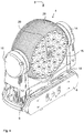
- FIG. 1 shows the first possible embodiment for the invention.
- a moving head light fixture 2 comprises a head 4 which head is rotatably supported in a yoke 6. Said yoke is rotatably supported by a base 8.
- the yoke comprises a first arm 10, a second arm 12 which first arm 10 ends in a bearing 14 which second arm 12 ends in a bearing 16.
- the bearings 14 and 16 are carrying the head 4.
- the head comprises at the front a number of lenses covering independent light sources.
- the lenses are forming three concentric circles at the figure 1 which outer circle is built of 16 lenses 20 where an circle placed inside comprises 12 lenses 22 and inside is further a circle of lenses comprising eight lenses 24.
- a blower 26 In the centre of the front end of the barrel is indicated a blower 26. Outside at the head 4 is indicated cooling dishes 28.
- Figure 2 shows the moving head light fixture seen from the rear with the head 4 is seen from the back side.
- the head 4 is carried at a yoke 6 which yoke is carried by a base 8.
- the yoke comprises legs 10 and 12 and bearings 14 and 16.
- the head 4 has a rear surface 25 comprises a first circle of lenses 30, a second light of lenses 32 and an inner circle of lenses 34. In the centre is shown a blower 36.
- Figure 3 shows the moving head light fixture 2 seen from the side.
- the head 4 is carried at the yoke 6 and the yoke 6 is carried by the base 1.
- the yoke 6 comprises a first leg 10 and a bearing 14 for carrying the head 4.
- the head 4 comprises a front end 15 and a rear end 25. Further is indicated the dishes 28 at figure 3 .
- Figure 4 shows a three-dimensional drawing of the invention. At figure 4 is seen the moving head light fixture seen from the front.
- the head 4 is carried by a yoke 6 and the yoke is carried by the base 8.
- the yoke comprises legs 10, 12 and bearings 14, 16.
- the yoke 6 comprises a bearing 18 by which it is rotating in relation to the base 8.
- the head 4 comprises the front end 15 which comprises three concentric circles of lenses where the outer circle comprises lenses 20, the next inner circle comprises lenses 22 and the inner circle comprises lenses 24. In the centre is indicated a blower 26. Further at figure 4 the dishes 28 are seen.
- a color emitting TIR lens or a parabolic reflector below the lenses 20, 22, 24 or 30, 32, 34 could be placed a color emitting TIR lens or a parabolic reflector.
- the light sources themselves can be different from light emitting diodes or it could be microwave resonators using bulbs for light generation.
Landscapes
- Engineering & Computer Science (AREA)
- General Engineering & Computer Science (AREA)
- Non-Portable Lighting Devices Or Systems Thereof (AREA)
Description
- The present invention relates to a moving head light fixture, which moving head light fixture comprises a light generating head, which head is carried in a yoke, which head is rotatable to the yoke, which yoke is rotatable to a base, which head comprises electronic circuits for LED control.
- Single sided moving head light fixtures are well-known.
-
FR 2 838 178 -
DE 199 17 401 discloses a lighting body comprising a number of LEDs mounted on at least one board and electrically interconnected, whereby the board is mounted between two plates of which at least one has openings corresponding to the LEDs on the board. The board with the LEDs and the plates are joined together to form a panel of sandwich construction.DE 199 17 401 discloses an embodiment where two panels of the lighting body have been provided. An outer panel has an opening into which an inner panel is fitted and connected to the outer panel through hinges. Further, the inner panel has a central opening and the inner edges of the opening are connected to suspension rod a by a hinge. The suspension rod is attached to a ceiling. -
DE 297 20 165 discloses a lighting device 1 including a spherical illuminating device, which is mounted on a base via a bearing arm. The illuminating device comprises a hollow ball formed of two half shells connected at a joint and has on its inside a cavity in which a lamp socket with an incandescent lamp is arranged. Both half shells have light transmission openings comprising colored lenses through which light from the incandescent lamp can pass. - It is the object of the pending application to form a double-sided moving head light fixture.
- This can be achieved by a moving head light fixture as described in the preamble to claim 1 where the moving head further comprises a front end and a rear end, which front end and rear end comprise a number of LEDs, and the LEDs at the front end and the LEDs at the rear end are independently controllable and configured to generate light into different directions
- Hereby it can be achieved that the moving head light fixture which is able at the same time to generate a light into different directions. By having independent control over the light sources in both directions, it is possible to control the light from an external controller independently in both directions. The light sources can be formed out of a multiple of single light sources and these light sources can generate light at different colors. In this way it should be possible by means of an external command to the moving head light fixture to control the color of the light as well in the front direction and also in the opposite rear direction.
- The moving head is in one embodiment barrel shaped. The barrel-shaped light fixture can rotate more or less freely in a yoke so that a double light beam can scan the room if the light barrel is rotated. As the yoke can also be rotated in relation to a base, a double rotation of the head can perform a double light beam which is moving in two different directions.
- The light sources can be formed of High Power LEDs. By using High Power LEDs for the light sources, it is possible to generate a relatively high intensity of light which light output can be further improved if the LEDs are operated together with TIR lenses which are able to concentrate the generated light from the LEDs.
- The light sources can also be formed of UV LEDs. The UV LEDs can be extremely powerful but in order to generate a visible light, a color conversion is necessary. This color conversion can be performed in a phosphor filter that can be placed above the UV LEDs or integrated into TIR lenses. These phosphor filters can convert the UV light into white light which will be highly intensive.
- The light sources can be formed of a video array consisting of low/medium power LEDs. It is possible at the end of the barrels to form a video array of e.g. LEDs so that the video output is generated from the end of the barrel.
- The light sources can be formed of white LEDs. By using white LEDs it is possible in the front of the LEDs to perform an active filtration and in this way generate colored light. Otherwise by non-filtration, it is possible to generate an extremely powerful light beam of white light.
- The light sources can be formed of Electrode Less Plasma Source (ELPS) bulb. By using the ELPS technology, it is possible to generate light at different colors but also white light can be generated and the light output will be extremely powerful. The ELSP can for instance be embodied as described in
US6737809 and its continuations or as described inWO0173806 - The barrel shaped casing can act as a heat sink. The barrel is formed of a number of dishes. These dishes are forming a very powerful heat sink. There will be extremely good airflow between the dishes and in that way effective cooling is achieved. Irrespective of which kind of light sources are used part of the power supplied to the light sources are coming out in the form of heat which has to be removed from the barrel.
- An active fan cooling can be built in the barrel shaped head to remove heat from the casing. In order to increase the cooling, a cooling fan can be placed in the barrel in order to increase the air circulation inside the barrel and also the air circulation between the dishes forming the barrel.
-
-
Figure 1 shows the first possible embodiment for the invention. -
Figure 2 shows the moving head light fixture seen from the rear. -
Figure 3 shows the movinghead light fixture 2 seen from the side. -
Figure 4 shows a three-dimensional drawing of the invention. -
Figure 1 shows the first possible embodiment for the invention. A movinghead light fixture 2 comprises ahead 4 which head is rotatably supported in ayoke 6. Said yoke is rotatably supported by abase 8. The yoke comprises afirst arm 10, asecond arm 12 whichfirst arm 10 ends in abearing 14 whichsecond arm 12 ends in abearing 16. Thebearings head 4. The head comprises at the front a number of lenses covering independent light sources. The lenses are forming three concentric circles at thefigure 1 which outer circle is built of 16lenses 20 where an circle placed inside comprises 12lenses 22 and inside is further a circle of lenses comprising eightlenses 24. In the centre of the front end of the barrel is indicated ablower 26. Outside at thehead 4 is indicatedcooling dishes 28. -
Figure 2 shows the moving head light fixture seen from the rear with thehead 4 is seen from the back side. Thehead 4 is carried at ayoke 6 which yoke is carried by abase 8. The yoke compriseslegs bearings head 4 has arear surface 25 comprises a first circle oflenses 30, a second light oflenses 32 and an inner circle oflenses 34. In the centre is shown ablower 36. -
Figure 3 shows the movinghead light fixture 2 seen from the side. Thehead 4 is carried at theyoke 6 and theyoke 6 is carried by the base 1. Theyoke 6 comprises afirst leg 10 and abearing 14 for carrying thehead 4. Thehead 4 comprises afront end 15 and arear end 25. Further is indicated thedishes 28 atfigure 3 . -
Figure 4 shows a three-dimensional drawing of the invention. Atfigure 4 is seen the moving head light fixture seen from the front. Thehead 4 is carried by ayoke 6 and the yoke is carried by thebase 8. The yoke compriseslegs bearings - The
yoke 6 comprises abearing 18 by which it is rotating in relation to thebase 8. Thehead 4 comprises thefront end 15 which comprises three concentric circles of lenses where the outer circle compriseslenses 20, the next inner circle compriseslenses 22 and the inner circle compriseslenses 24. In the centre is indicated ablower 26. Further atfigure 4 thedishes 28 are seen. - Below the
lenses
Claims (8)
- Moving head light fixture (2), which moving head light fixture comprises a light generating head (4), which head is carried in a yoke (6), said yoke comprises a first arm (10) and a second arm (12) where said first arm comprises a bearing (14) and said second arm comprises a bearing (16), said bearings are carrying said head and which head is rotatable to the yoke, which yoke is rotatable to a base (8), which head comprises a number of LEDs and electronic circuits for LED control, characterized in that said moving head comprises a front end (15) and rear end (25), which front end and rear end comprise a said number of LEDs and said LEDs at said front end and said LEDs at said rear end are independently controllable and configured to generate light into different directions, where at least one of said number of LEDs at said front end is formed of High Power LEDs and where said number of LEDs of said rear end form a video array of low/medium power LEDs.
- Moving head light fixture according to claim 1, characterized in that the moving head is barrel shaped.
- Moving head light fixture according to claims 1-2, characterized in that at least one of said number of LEDs are formed of UV LEDs.
- Moving head light fixture according to claims 1-3, characterized in that at least one of said number of LEDs are formed of white LEDs.
- Moving head light fixture according to claims 1-4, characterized in that the barrel shaped casing acts as a heat sink.
- Moving head light fixture according to claim 5, characterized in that and active fan cooling is built in the barrel shaped head to remove heat from the casing.
- Moving head light fixture according to claims 1-6, characterized in said front end comprises a number of lenses covering independent LEDs.
- Moving Head light fixture according to claims 1-7, characterized in that said front end comprises TIR lenses configured to concentrate the generated light from said High Power LEDs.
Applications Claiming Priority (2)
| Application Number | Priority Date | Filing Date | Title |
|---|---|---|---|
| DKPA200801234 | 2008-09-05 | ||
| PCT/DK2009/050226 WO2010025737A1 (en) | 2008-09-05 | 2009-09-04 | Double sided light fixture |
Publications (3)
| Publication Number | Publication Date |
|---|---|
| EP2324282A1 EP2324282A1 (en) | 2011-05-25 |
| EP2324282A4 EP2324282A4 (en) | 2014-03-19 |
| EP2324282B1 true EP2324282B1 (en) | 2017-12-06 |
Family
ID=41796763
Family Applications (1)
| Application Number | Title | Priority Date | Filing Date |
|---|---|---|---|
| EP09811068.7A Active EP2324282B1 (en) | 2008-09-05 | 2009-09-04 | Double sided light fixture |
Country Status (4)
| Country | Link |
|---|---|
| US (1) | US8469546B2 (en) |
| EP (1) | EP2324282B1 (en) |
| CN (1) | CN102144123B (en) |
| WO (1) | WO2010025737A1 (en) |
Cited By (1)
| Publication number | Priority date | Publication date | Assignee | Title |
|---|---|---|---|---|
| WO2021094280A1 (en) * | 2019-11-13 | 2021-05-20 | Signify Holding B.V. | Lighting device |
Families Citing this family (34)
| Publication number | Priority date | Publication date | Assignee | Title |
|---|---|---|---|---|
| US8708535B2 (en) * | 2010-02-16 | 2014-04-29 | Martin Professional A/S | Illumination device with interlocked yoke shell parts |
| US8950895B2 (en) | 2010-04-23 | 2015-02-10 | Martin Professional Aps | Moving head light fixture with protruding diffuser cover and multiple light sources |
| US9326347B2 (en) | 2010-04-23 | 2016-04-26 | Martin Professional Aps | Light fixture with background display using diffuse pixels between nondiffuse light sources |
| CA2774787C (en) * | 2011-04-18 | 2018-08-21 | Kirkor Kiremitci | Oscillating photo light therapy device |
| CA2774786C (en) | 2011-04-18 | 2019-07-02 | Kirkor Kiremitci | Photo light therapy and massaging apparatus |
| US8545043B2 (en) * | 2011-11-10 | 2013-10-01 | Day Sun Industrial Corp. | Illumination device for providing synchronous forward and backward lighting |
| USD679446S1 (en) * | 2011-11-17 | 2013-04-02 | Myotek Pacific Corp. | LED spot lamp |
| CN102418868B (en) * | 2011-12-07 | 2014-02-19 | 胡宇峰 | Universal swinging angle revolving light |
| USD694926S1 (en) * | 2011-12-09 | 2013-12-03 | Martin Professional A/S | Lighting fixture |
| FR2988464B1 (en) * | 2012-03-20 | 2015-05-15 | Ayrton | LUMINOUS DEVICE COMPRISING A PROJECTOR COMPRISING A PLURALITY OF LIGHT SOURCES |
| USD694466S1 (en) * | 2012-09-21 | 2013-11-26 | Martin Professional A/S | Yoke for a lighting fixture |
| USD694462S1 (en) * | 2012-09-21 | 2013-11-26 | Martin Professional A/S | Head for a lighting fixture |
| USD694467S1 (en) * | 2012-09-21 | 2013-11-26 | Martin Professional A/S | Base for a lighting fixture |
| CN103162099A (en) * | 2013-03-05 | 2013-06-19 | 长春亿思达科技发展集团有限公司 | Light-emitting diode (LED) flashlight |
| CN103225789B (en) * | 2013-04-27 | 2015-12-09 | 广州市浩洋电子有限公司 | A kind of two-way bright dipping computer stage lighting |
| US9587805B2 (en) * | 2013-09-20 | 2017-03-07 | Osram Sylvania Inc. | Solid-state luminaire with electronically adjustable light beam distribution |
| CN103727441A (en) * | 2013-12-19 | 2014-04-16 | 张孙贤 | Enameled-wire LED multicolor flashing lamp |
| USD743078S1 (en) * | 2014-02-05 | 2015-11-10 | Revolution Display, Llc | Moving stage light with light tube |
| USD712087S1 (en) * | 2014-03-06 | 2014-08-26 | Martin Professional Aps | Light lens |
| US20180156430A1 (en) * | 2014-11-20 | 2018-06-07 | Sgm Light A/S | Moving head lamp |
| CN105716033B (en) * | 2016-03-31 | 2019-11-12 | 广州市浩洋电子股份有限公司 | A multi-lamp stage lamp |
| CN110792996A (en) * | 2019-11-11 | 2020-02-14 | 西安弘创信息技术有限责任公司 | LED combined mother and child lamp of intelligent lighting system |
| US11073268B1 (en) * | 2020-10-27 | 2021-07-27 | GVM Photographic Equipment Inc. | Double-sided LED panel light |
| USD957507S1 (en) | 2021-04-14 | 2022-07-12 | ZhiSheng Xu | Double-sided on-camera light with cold shoe head |
| US11577856B1 (en) | 2022-02-28 | 2023-02-14 | Honeywell International Inc. | Dual sided aircraft light assembly |
| USD1092816S1 (en) * | 2022-04-06 | 2025-09-09 | Glp German Light Products Gmbh | Spot light for stage lighting |
| USD1036736S1 (en) * | 2022-06-05 | 2024-07-23 | Shenzhen Snc Opto Electronic Co., Ltd | LED lamp |
| USD1023384S1 (en) * | 2022-06-09 | 2024-04-16 | Linlin Zhao | Stage light |
| USD1032903S1 (en) * | 2022-07-19 | 2024-06-25 | MercuryPM Pty Ltd | Spotlight |
| USD1035956S1 (en) * | 2022-08-02 | 2024-07-16 | Wuxi AHLights Technology Co., LTD | LED beam pattern moving head light |
| USD1023387S1 (en) * | 2022-09-16 | 2024-04-16 | Xiaozhu Zhang | Stage light |
| USD1036737S1 (en) * | 2022-11-03 | 2024-07-23 | Harman International Industries, Incorporated | Lighting device |
| CN222459348U (en) * | 2024-05-31 | 2025-02-11 | 广州市浩洋电子股份有限公司 | A stage light with waterproof support frame |
| CN119713204A (en) * | 2025-02-26 | 2025-03-28 | 吕梁学院 | General venue place disinfection illumination heat preservation device |
Citations (1)
| Publication number | Priority date | Publication date | Assignee | Title |
|---|---|---|---|---|
| FR2838178A1 (en) * | 2002-04-09 | 2003-10-10 | Oxo | MULTIDIRECTIONAL LED PROJECTOR |
Family Cites Families (10)
| Publication number | Priority date | Publication date | Assignee | Title |
|---|---|---|---|---|
| US3878506A (en) * | 1973-08-03 | 1975-04-15 | David W Young | Airport lighting and radar reflector combination |
| DE29720165U1 (en) | 1997-11-14 | 1998-02-12 | Dapo-Leuchten Vertriebs GmbH, 68789 St Leon-Rot | Lighting device |
| DE19917401A1 (en) * | 1999-04-16 | 2000-10-26 | Hauke Haller | Lighting body has board between two plates, of which at least one has openings corresponding. to LEDs on board; board with LEDs and plates are joined together to form panel |
| DE20007235U1 (en) * | 1999-05-19 | 2000-07-27 | Agon Tech Corp., Chung-Ho, Taipeh | General purpose lamp |
| WO2001073806A1 (en) | 2000-03-27 | 2001-10-04 | Digital Reflections, Inc. | Improved high intensity light source |
| DE20007687U1 (en) * | 2000-04-26 | 2001-01-04 | Superstar Lighting Co., Ltd., San Chung, Taipeh | Lighting device |
| US6737809B2 (en) | 2000-07-31 | 2004-05-18 | Luxim Corporation | Plasma lamp with dielectric waveguide |
| US7600891B2 (en) * | 2006-09-07 | 2009-10-13 | Belliveau Richard S | Theatre light apparatus incorporating LED tracking system |
| US20100328466A1 (en) * | 2006-11-01 | 2010-12-30 | Videolarm, Inc. | Infrared illuminator with variable beam angle |
| US7954981B2 (en) * | 2008-06-10 | 2011-06-07 | Martin Professional A/S | Light source module for a light fixture |
-
2009
- 2009-09-04 CN CN2009801344691A patent/CN102144123B/en active Active
- 2009-09-04 WO PCT/DK2009/050226 patent/WO2010025737A1/en not_active Ceased
- 2009-09-04 EP EP09811068.7A patent/EP2324282B1/en active Active
- 2009-09-04 US US13/062,584 patent/US8469546B2/en active Active
Patent Citations (1)
| Publication number | Priority date | Publication date | Assignee | Title |
|---|---|---|---|---|
| FR2838178A1 (en) * | 2002-04-09 | 2003-10-10 | Oxo | MULTIDIRECTIONAL LED PROJECTOR |
Cited By (1)
| Publication number | Priority date | Publication date | Assignee | Title |
|---|---|---|---|---|
| WO2021094280A1 (en) * | 2019-11-13 | 2021-05-20 | Signify Holding B.V. | Lighting device |
Also Published As
| Publication number | Publication date |
|---|---|
| US20110199770A1 (en) | 2011-08-18 |
| US8469546B2 (en) | 2013-06-25 |
| WO2010025737A1 (en) | 2010-03-11 |
| EP2324282A4 (en) | 2014-03-19 |
| EP2324282A1 (en) | 2011-05-25 |
| CN102144123B (en) | 2013-01-16 |
| CN102144123A (en) | 2011-08-03 |
Similar Documents
| Publication | Publication Date | Title |
|---|---|---|
| US8469546B2 (en) | Double sided light fixture | |
| US6634779B2 (en) | Method and apparatus for linear led lighting | |
| JP4653120B2 (en) | Lighting equipment | |
| US20050174780A1 (en) | LED light | |
| CN110345414A (en) | Lighting device | |
| US11873986B2 (en) | Fan lamp with directional light and floodlight and retractable blade assembly | |
| US8388178B2 (en) | LED cyclorama light | |
| CN103225789B (en) | A kind of two-way bright dipping computer stage lighting | |
| CN104819414A (en) | Stage lamp for lighting at multiple angles | |
| TWI512232B (en) | Light emitting diode bulb | |
| EP2753877A1 (en) | Led cooling system | |
| EP2550673B1 (en) | Plasma light source automated luminaire | |
| CN102829350B (en) | Multifunctional LED (Light-emitting Diode) lamp with double light sources | |
| KR101057678B1 (en) | Lighting equipment | |
| US10324266B1 (en) | LED light projection with multiple lenses | |
| CN212057006U (en) | Fan lamp | |
| CN103375693A (en) | Lighting device, omnidirectional lighting lamp and reshaped lamp both with same | |
| CN204611519U (en) | A kind of stage lighting of multi-angle luminescence | |
| CN202209646U (en) | LED (Light Emitting Diode) lamp capable of lighting in side direction | |
| CN105822925B (en) | Corn lamp | |
| CN212057007U (en) | Fan lamp | |
| JP4106525B2 (en) | LED lighting device | |
| CN222669720U (en) | Lamp with starlight and colorful effects | |
| CN117308005B (en) | LED illuminating lamp | |
| CN102865519B (en) | A kind of concealed Down lamp of shaking the head |
Legal Events
| Date | Code | Title | Description |
|---|---|---|---|
| PUAI | Public reference made under article 153(3) epc to a published international application that has entered the european phase |
Free format text: ORIGINAL CODE: 0009012 |
|
| 17P | Request for examination filed |
Effective date: 20110314 |
|
| AK | Designated contracting states |
Kind code of ref document: A1 Designated state(s): AT BE BG CH CY CZ DE DK EE ES FI FR GB GR HR HU IE IS IT LI LT LU LV MC MK MT NL NO PL PT RO SE SI SK SM TR |
|
| AX | Request for extension of the european patent |
Extension state: AL BA RS |
|
| DAX | Request for extension of the european patent (deleted) | ||
| A4 | Supplementary search report drawn up and despatched |
Effective date: 20140217 |
|
| RIC1 | Information provided on ipc code assigned before grant |
Ipc: F21S 10/00 20060101AFI20140211BHEP Ipc: F21W 131/406 20060101ALI20140211BHEP |
|
| 17Q | First examination report despatched |
Effective date: 20161221 |
|
| GRAP | Despatch of communication of intention to grant a patent |
Free format text: ORIGINAL CODE: EPIDOSNIGR1 |
|
| INTG | Intention to grant announced |
Effective date: 20170627 |
|
| GRAS | Grant fee paid |
Free format text: ORIGINAL CODE: EPIDOSNIGR3 |
|
| GRAA | (expected) grant |
Free format text: ORIGINAL CODE: 0009210 |
|
| AK | Designated contracting states |
Kind code of ref document: B1 Designated state(s): AT BE BG CH CY CZ DE DK EE ES FI FR GB GR HR HU IE IS IT LI LT LU LV MC MK MT NL NO PL PT RO SE SI SK SM TR |
|
| REG | Reference to a national code |
Ref country code: GB Ref legal event code: FG4D |
|
| REG | Reference to a national code |
Ref country code: AT Ref legal event code: REF Ref document number: 952710 Country of ref document: AT Kind code of ref document: T Effective date: 20171215 Ref country code: CH Ref legal event code: EP |
|
| REG | Reference to a national code |
Ref country code: IE Ref legal event code: FG4D |
|
| REG | Reference to a national code |
Ref country code: DE Ref legal event code: R096 Ref document number: 602009049771 Country of ref document: DE |
|
| REG | Reference to a national code |
Ref country code: NL Ref legal event code: MP Effective date: 20171206 |
|
| REG | Reference to a national code |
Ref country code: LT Ref legal event code: MG4D |
|
| PG25 | Lapsed in a contracting state [announced via postgrant information from national office to epo] |
Ref country code: NO Free format text: LAPSE BECAUSE OF FAILURE TO SUBMIT A TRANSLATION OF THE DESCRIPTION OR TO PAY THE FEE WITHIN THE PRESCRIBED TIME-LIMIT Effective date: 20180306 Ref country code: SE Free format text: LAPSE BECAUSE OF FAILURE TO SUBMIT A TRANSLATION OF THE DESCRIPTION OR TO PAY THE FEE WITHIN THE PRESCRIBED TIME-LIMIT Effective date: 20171206 Ref country code: FI Free format text: LAPSE BECAUSE OF FAILURE TO SUBMIT A TRANSLATION OF THE DESCRIPTION OR TO PAY THE FEE WITHIN THE PRESCRIBED TIME-LIMIT Effective date: 20171206 Ref country code: ES Free format text: LAPSE BECAUSE OF FAILURE TO SUBMIT A TRANSLATION OF THE DESCRIPTION OR TO PAY THE FEE WITHIN THE PRESCRIBED TIME-LIMIT Effective date: 20171206 Ref country code: LT Free format text: LAPSE BECAUSE OF FAILURE TO SUBMIT A TRANSLATION OF THE DESCRIPTION OR TO PAY THE FEE WITHIN THE PRESCRIBED TIME-LIMIT Effective date: 20171206 |
|
| REG | Reference to a national code |
Ref country code: AT Ref legal event code: MK05 Ref document number: 952710 Country of ref document: AT Kind code of ref document: T Effective date: 20171206 |
|
| PG25 | Lapsed in a contracting state [announced via postgrant information from national office to epo] |
Ref country code: BG Free format text: LAPSE BECAUSE OF FAILURE TO SUBMIT A TRANSLATION OF THE DESCRIPTION OR TO PAY THE FEE WITHIN THE PRESCRIBED TIME-LIMIT Effective date: 20180306 Ref country code: HR Free format text: LAPSE BECAUSE OF FAILURE TO SUBMIT A TRANSLATION OF THE DESCRIPTION OR TO PAY THE FEE WITHIN THE PRESCRIBED TIME-LIMIT Effective date: 20171206 Ref country code: LV Free format text: LAPSE BECAUSE OF FAILURE TO SUBMIT A TRANSLATION OF THE DESCRIPTION OR TO PAY THE FEE WITHIN THE PRESCRIBED TIME-LIMIT Effective date: 20171206 Ref country code: GR Free format text: LAPSE BECAUSE OF FAILURE TO SUBMIT A TRANSLATION OF THE DESCRIPTION OR TO PAY THE FEE WITHIN THE PRESCRIBED TIME-LIMIT Effective date: 20180307 |
|
| PG25 | Lapsed in a contracting state [announced via postgrant information from national office to epo] |
Ref country code: NL Free format text: LAPSE BECAUSE OF FAILURE TO SUBMIT A TRANSLATION OF THE DESCRIPTION OR TO PAY THE FEE WITHIN THE PRESCRIBED TIME-LIMIT Effective date: 20171206 |
|
| PG25 | Lapsed in a contracting state [announced via postgrant information from national office to epo] |
Ref country code: SK Free format text: LAPSE BECAUSE OF FAILURE TO SUBMIT A TRANSLATION OF THE DESCRIPTION OR TO PAY THE FEE WITHIN THE PRESCRIBED TIME-LIMIT Effective date: 20171206 Ref country code: EE Free format text: LAPSE BECAUSE OF FAILURE TO SUBMIT A TRANSLATION OF THE DESCRIPTION OR TO PAY THE FEE WITHIN THE PRESCRIBED TIME-LIMIT Effective date: 20171206 Ref country code: CZ Free format text: LAPSE BECAUSE OF FAILURE TO SUBMIT A TRANSLATION OF THE DESCRIPTION OR TO PAY THE FEE WITHIN THE PRESCRIBED TIME-LIMIT Effective date: 20171206 |
|
| REG | Reference to a national code |
Ref country code: FR Ref legal event code: PLFP Year of fee payment: 10 |
|
| PG25 | Lapsed in a contracting state [announced via postgrant information from national office to epo] |
Ref country code: SM Free format text: LAPSE BECAUSE OF FAILURE TO SUBMIT A TRANSLATION OF THE DESCRIPTION OR TO PAY THE FEE WITHIN THE PRESCRIBED TIME-LIMIT Effective date: 20171206 Ref country code: PL Free format text: LAPSE BECAUSE OF FAILURE TO SUBMIT A TRANSLATION OF THE DESCRIPTION OR TO PAY THE FEE WITHIN THE PRESCRIBED TIME-LIMIT Effective date: 20171206 Ref country code: RO Free format text: LAPSE BECAUSE OF FAILURE TO SUBMIT A TRANSLATION OF THE DESCRIPTION OR TO PAY THE FEE WITHIN THE PRESCRIBED TIME-LIMIT Effective date: 20171206 Ref country code: IT Free format text: LAPSE BECAUSE OF FAILURE TO SUBMIT A TRANSLATION OF THE DESCRIPTION OR TO PAY THE FEE WITHIN THE PRESCRIBED TIME-LIMIT Effective date: 20171206 Ref country code: AT Free format text: LAPSE BECAUSE OF FAILURE TO SUBMIT A TRANSLATION OF THE DESCRIPTION OR TO PAY THE FEE WITHIN THE PRESCRIBED TIME-LIMIT Effective date: 20171206 |
|
| REG | Reference to a national code |
Ref country code: DE Ref legal event code: R097 Ref document number: 602009049771 Country of ref document: DE |
|
| REG | Reference to a national code |
Ref country code: DE Ref legal event code: R081 Ref document number: 602009049771 Country of ref document: DE Owner name: HARMAN PROFESSIONAL DENMARK APS, DK Free format text: FORMER OWNER: MARTIN PROFESSIONAL A/S, AARHUS, DK |
|
| PLBE | No opposition filed within time limit |
Free format text: ORIGINAL CODE: 0009261 |
|
| STAA | Information on the status of an ep patent application or granted ep patent |
Free format text: STATUS: NO OPPOSITION FILED WITHIN TIME LIMIT |
|
| 26N | No opposition filed |
Effective date: 20180907 |
|
| PG25 | Lapsed in a contracting state [announced via postgrant information from national office to epo] |
Ref country code: SI Free format text: LAPSE BECAUSE OF FAILURE TO SUBMIT A TRANSLATION OF THE DESCRIPTION OR TO PAY THE FEE WITHIN THE PRESCRIBED TIME-LIMIT Effective date: 20171206 Ref country code: DK Free format text: LAPSE BECAUSE OF FAILURE TO SUBMIT A TRANSLATION OF THE DESCRIPTION OR TO PAY THE FEE WITHIN THE PRESCRIBED TIME-LIMIT Effective date: 20171206 |
|
| PG25 | Lapsed in a contracting state [announced via postgrant information from national office to epo] |
Ref country code: MC Free format text: LAPSE BECAUSE OF FAILURE TO SUBMIT A TRANSLATION OF THE DESCRIPTION OR TO PAY THE FEE WITHIN THE PRESCRIBED TIME-LIMIT Effective date: 20171206 |
|
| REG | Reference to a national code |
Ref country code: CH Ref legal event code: PL |
|
| REG | Reference to a national code |
Ref country code: BE Ref legal event code: MM Effective date: 20180930 |
|
| REG | Reference to a national code |
Ref country code: IE Ref legal event code: MM4A |
|
| PG25 | Lapsed in a contracting state [announced via postgrant information from national office to epo] |
Ref country code: LU Free format text: LAPSE BECAUSE OF NON-PAYMENT OF DUE FEES Effective date: 20180904 |
|
| PG25 | Lapsed in a contracting state [announced via postgrant information from national office to epo] |
Ref country code: IE Free format text: LAPSE BECAUSE OF NON-PAYMENT OF DUE FEES Effective date: 20180904 |
|
| PG25 | Lapsed in a contracting state [announced via postgrant information from national office to epo] |
Ref country code: CH Free format text: LAPSE BECAUSE OF NON-PAYMENT OF DUE FEES Effective date: 20180930 Ref country code: BE Free format text: LAPSE BECAUSE OF NON-PAYMENT OF DUE FEES Effective date: 20180930 Ref country code: LI Free format text: LAPSE BECAUSE OF NON-PAYMENT OF DUE FEES Effective date: 20180930 |
|
| PGFP | Annual fee paid to national office [announced via postgrant information from national office to epo] |
Ref country code: FR Payment date: 20190820 Year of fee payment: 11 |
|
| PG25 | Lapsed in a contracting state [announced via postgrant information from national office to epo] |
Ref country code: MT Free format text: LAPSE BECAUSE OF NON-PAYMENT OF DUE FEES Effective date: 20180904 |
|
| PG25 | Lapsed in a contracting state [announced via postgrant information from national office to epo] |
Ref country code: TR Free format text: LAPSE BECAUSE OF FAILURE TO SUBMIT A TRANSLATION OF THE DESCRIPTION OR TO PAY THE FEE WITHIN THE PRESCRIBED TIME-LIMIT Effective date: 20171206 |
|
| PG25 | Lapsed in a contracting state [announced via postgrant information from national office to epo] |
Ref country code: PT Free format text: LAPSE BECAUSE OF FAILURE TO SUBMIT A TRANSLATION OF THE DESCRIPTION OR TO PAY THE FEE WITHIN THE PRESCRIBED TIME-LIMIT Effective date: 20171206 Ref country code: HU Free format text: LAPSE BECAUSE OF FAILURE TO SUBMIT A TRANSLATION OF THE DESCRIPTION OR TO PAY THE FEE WITHIN THE PRESCRIBED TIME-LIMIT; INVALID AB INITIO Effective date: 20090904 |
|
| PG25 | Lapsed in a contracting state [announced via postgrant information from national office to epo] |
Ref country code: CY Free format text: LAPSE BECAUSE OF FAILURE TO SUBMIT A TRANSLATION OF THE DESCRIPTION OR TO PAY THE FEE WITHIN THE PRESCRIBED TIME-LIMIT Effective date: 20171206 Ref country code: MK Free format text: LAPSE BECAUSE OF NON-PAYMENT OF DUE FEES Effective date: 20171206 |
|
| PG25 | Lapsed in a contracting state [announced via postgrant information from national office to epo] |
Ref country code: IS Free format text: LAPSE BECAUSE OF FAILURE TO SUBMIT A TRANSLATION OF THE DESCRIPTION OR TO PAY THE FEE WITHIN THE PRESCRIBED TIME-LIMIT Effective date: 20180406 |
|
| PG25 | Lapsed in a contracting state [announced via postgrant information from national office to epo] |
Ref country code: FR Free format text: LAPSE BECAUSE OF NON-PAYMENT OF DUE FEES Effective date: 20200930 |
|
| P01 | Opt-out of the competence of the unified patent court (upc) registered |
Effective date: 20230527 |
|
| PGFP | Annual fee paid to national office [announced via postgrant information from national office to epo] |
Ref country code: DE Payment date: 20250820 Year of fee payment: 17 |
|
| PGFP | Annual fee paid to national office [announced via postgrant information from national office to epo] |
Ref country code: GB Payment date: 20250820 Year of fee payment: 17 |