EP2323945B1 - Method and system for cork removal - Google Patents
Method and system for cork removal Download PDFInfo
- Publication number
- EP2323945B1 EP2323945B1 EP09806519.6A EP09806519A EP2323945B1 EP 2323945 B1 EP2323945 B1 EP 2323945B1 EP 09806519 A EP09806519 A EP 09806519A EP 2323945 B1 EP2323945 B1 EP 2323945B1
- Authority
- EP
- European Patent Office
- Prior art keywords
- cover
- gas
- gas cell
- sealing member
- cell
- Prior art date
- Legal status (The legal status is an assumption and is not a legal conclusion. Google has not performed a legal analysis and makes no representation as to the accuracy of the status listed.)
- Active
Links
Images


Classifications
-
- B—PERFORMING OPERATIONS; TRANSPORTING
- B67—OPENING, CLOSING OR CLEANING BOTTLES, JARS OR SIMILAR CONTAINERS; LIQUID HANDLING
- B67B—APPLYING CLOSURE MEMBERS TO BOTTLES JARS, OR SIMILAR CONTAINERS; OPENING CLOSED CONTAINERS
- B67B7/00—Hand- or power-operated devices for opening closed containers
- B67B7/02—Hand- or power-operated devices for opening closed containers for removing stoppers
- B67B7/06—Other cork removers
- B67B7/08—Other cork removers using air or gas pressure
-
- B—PERFORMING OPERATIONS; TRANSPORTING
- B65—CONVEYING; PACKING; STORING; HANDLING THIN OR FILAMENTARY MATERIAL
- B65D—CONTAINERS FOR STORAGE OR TRANSPORT OF ARTICLES OR MATERIALS, e.g. BAGS, BARRELS, BOTTLES, BOXES, CANS, CARTONS, CRATES, DRUMS, JARS, TANKS, HOPPERS, FORWARDING CONTAINERS; ACCESSORIES, CLOSURES, OR FITTINGS THEREFOR; PACKAGING ELEMENTS; PACKAGES
- B65D39/00—Closures arranged within necks or pouring openings or in discharge apertures, e.g. stoppers
- B65D39/16—Closures arranged within necks or pouring openings or in discharge apertures, e.g. stoppers with handles or other special means facilitating manual actuation
Description
- The invention is in the field of drink and food industries, and in special it deals with removal of corks out of wine bottles. In particular the invention relates to a cover for a container according to the preamble of claim 1 and to a method according to the preamble of claim 13, as known from
US 3,135,410 . - Good wines are often sold in glass bottles having cork cover for sealing. To drink the wine, a waiter or an owner of the bottle has to remove the cork out of the bottle. A special device, a wine opener or a corkscrew, is screwed into the cork and a lever arm of the opener is used to extract the cork out of the bottleneck.
- For comparison, food/drink hermetically sealed metal containers or cans had been sold in the past without any attached can opener, and part of them are so made also nowadays. To use them while traveling, the user had to take with him a can opener. However, for many years already, most cans are sold with an attached opener and can be easily opened without a need to provide a can opener.
- It would be advantageous to provide a system and a method for opening wine bottles having a cork without any need for a special opener, or in other words to have opening means as part of the bottle.
- It is provided according to the present invention, a cover for a container having internal volume and an opening according to claim 1.
- In some embodiments, the container is a bottle and the sealing member is a cork.
- In some embodiments, the compressed gas has initial pressure from 1.5 to 3.0 bar, and it includes air, nitrogen, or helium.
- In some embodiments, the cover includes safety means to prevent accidental activation of the gas channel mechanism.
- In some embodiments, the gas channel mechanism includes an elongated duct having a sharp end, the sharp end is adapted for penetrating the sealing member upon pushing of the elongated duct towards the container. The portion of the sealing member penetrated by the sharp end is preferably 1-3 mm thick. The gas channel mechanism preferably includes means for hiding the sharp end within the sealing member while the compressed gas pushes the cover outwardly, thereby preventing injury by the sharp end of a person opening the cover. The elongated duct is preferably cylindrically shaped with an outside diameter from 1.0 to 2.0 mm.
- In some embodiments, the gas cell is cylindrically shaped with an outside diameter from 8 to 12 mm.
- In some embodiments, the sealing member is made of cork, wood, paper, polymer, or rubber. The gas cell is made of aluminum, steel, or polymer.
- It is also provided according to the present invention, a method for handling an opening of a container having internal volume according to claim 13.
- Preferably, activating includes the actions of rotating the gas cell relative to the ferrule, sliding the gas cell within the ferrule towards the container, breaking out a diaphragm sealing the gas cell, and penetrating the sealing member.
- The subject matter regarded as the invention is particularly pointed out and distinctly claimed in the concluding portion of the specification. The invention, however, both as to system organization and method of operation, together with features and advantages thereof, may best be understood by reference to the following detailed description when read with the accompanied drawings in which:
-
Fig. 1 illustrates a bottle of wine opened by a gas jet from within a cork. -
Fig. 2a depicts a gas cell within a cork with a channel gas mechanism before activation. -
Fig. 2b is an expanded view of the upper part of the gas channel mechanism before activation. -
Fig. 3a depicts the gas channel mechanism after activation. -
Fig. 3b is an expanded view of the upper part of the gas channel mechanism after activation. -
Fig. 3c is an expanded view of a part of the gas channel mechanism after activation. -
Fig. 4 illustrates a flow chart of a method for handling an opening of a container. -
Fig. 5a is an exploded view of the gas cell and the gas channel mechanism. -
Fig. 5b is an exploded view of the ferrule and the gas cell having the gas channel mechanism there within. -
Fig. 5c is a top perspective view of the cover with a handle before activation of the gas channel mechanism. -
Fig. 6a shows the ferrule and the gas cell before activation. -
Fig. 6b shows the ferrule and the gas cell after rotation. -
Fig. 6c shows the ferrule and the gas cell after sliding the gas cell within the ferrule towards the bottle. -
Fig. 7 shows a safety measure for preventing uncontrolled activation of the gas channel mechanism. -
Fig. 8 illustrates a flow chart of a method for activating the gas channel mechanism. - The present invention will now be described in terms of specific example embodiments. It is to be understood that the invention is not limited to the example embodiments disclosed. It should also be understood that not every feature of the methods and systems handling the described cover is necessary to implement the invention as claimed in any particular one of the appended claims. Various elements and features of device are described to fully enable the invention. It should also be understood that throughout this disclosure, where a method is shown or described, the steps of the method may be performed in any order or simultaneously, unless it is clear from the context that one step depends on another being performed first.
- Before explaining several embodiments of the invention in detail, it is to be understood that the invention is not limited in its application to the details of construction and the arrangement of the components set forth in the following description or illustrated in the drawings. The invention is capable of other embodiments or of being practiced or carried out in various ways within the scope of the appended claims. Also, it is to be understood that the phraseology and terminology employed herein is for the purpose of description and should not be regarded as limiting.
- Unless otherwise defined, all technical and scientific terms used herein have the same meaning as commonly understood by one of ordinary skill in the art to which this invention belongs. The systems, methods, and examples provided herein are illustrative only and not intended to be limiting.
- In the description and claims of the present application, each of the verbs "comprise", "include" and "have", and conjugates thereof, are used to indicate that the object or objects of the verb are not necessarily a complete listing of members, components, elements or parts of the subject or subjects of the verb.
- Referring to
Fig. 1 , it is provided acover 10 for acontainer 20 havinginternal volume 30 and anopening 40. In the example ofFig. 1 , thecontainer 10 is awine bottle 20 having acork 50 as a sealing member for opening 40 which is disposed at the end ofbottleneck 55.Fig. 1 illustrates the opening ofbottle 10, whereas agas jet 60 is sprayed into theinternal volume 30 abovewine level 70, increasing the gas pressure involume 30. The increased pressure pushes cover 10 outwardly, either completely or at least enough to allow a user to conveniently removecover 10 by tiltingcover 10 aside. Also shown inFig. 1 is arotating handle 80 which operation is explained bellow. -
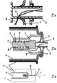
Figs. 2 and3 illustrate the mechanism for sprayinggas jet 60 intointernal volume 30.Fig. 2a depictscover 10 at rest, before openingbottle 20.Cover 10 includescork 50 for sealingopening 40, agas cell 90 containing compressed gas, and agas channel mechanism 100 for constituting a gas channel between thegas cell 90 and theinternal volume 30. Preferably, the compressed gas has an initial pressure level from 1.5 to 3.0 bar, and the gas includes air, nitrogen, or helium.Cylindrical gas cell 90 preferably has an outside diameter from 8 to 12 mm. - A
ferrule 110 is disposed betweengas cell 90 and an interior part ofcork 50, whereasgas cell 90 is slidably coupled toferrule 110. - The
gas channel mechanism 100 includes anelongated duct 120 having asharp end 130.Sharp end 130 is adapted for penetratingcork 50 upon pushing ofelongated duct 120 towardscontainer 10. For that aim,elongated duct 120 is preferably cylindrically shaped with an outside diameter from 1.0 to 2.0 mm. The portion ofcork 50 to be penetrated by thesharp end 130 is preferably 1-3 mm thick. -
Duct 120 has anaperture 135 on a side, for connecting the duct interior tovolume 140, which is enclosed betweenduct 120 and an enclosingannulus 145.Duct 120 is attached to acylinder 150, which in turn is attached tocylindrical post 155. Aspring 160 is disposed onpost 155, supported bycylinder 150 on one end and limited by anhousing 165 on the other end. Adiaphragm 170 seals abore 175 inhousing 165, and a thickelastic ring 180 encirclesduct 120outside housing 165. - Referring now to
Figs. 3a, 3b and 3c , activating the gas channel mechanism is made by slidably pushinggas cell 90 insideferrule 110 towardsbottle 20. Assharp edge 130 approaches the cork, there is some resistance to penetration and the end ofpost 155 breaks diaphragm 170. Consequently, the compressed gas residing ingas cell 90 expands intovolume 185. At the same time, the movement ofpost 155, attachedcylinder 150 andduct 120 towards the interior ofgas cell 90, slidesannulus 145 relative toduct 120 and exposesaperture 135 tovolume 185. Consequently, the compressed gas flows intoduct 120, as exemplified bygas flow line 190. - Further pushing of
gas cell 90 towardsbottle 20 applies force onspring 160 which in turn pushesduct 120 towardsbottle 20 such thatsharp end 130 penetratescork 50, allowing the compressed gas enter intointernal volume 30, thus constituting a gas channel betweengas cell 90 andinternal volume 30. The compressed gas pushes cover 10 outwardly, facilitating opening ofbottle 20.Bottle 20 may be opened either by total removal ofcover 10 out of opening 40 by the pressurized gas, or by enabling the user to complete the cover removal by tilting the cover aside. -
Gas channel mechanism 100 preferably includes means for hidingsharp end 130 while the compressed gas pushescork 50 outwardly, thereby preventing injury bysharp end 130 of aperson opening cover 10. Thickelastic ring 180 ofFigs 2 and3 serves as an exemplary hiding means. While pushinggas cell 90 towardsbottle 20, thickelastic ring 180 is pressed againstcork 50 and becomes somewhat thinner. As pushinggas cell 90 stops and cover 10 gets out by the compressed gas,ring 180 expands enough to drawduct 120 intogas cell 90, hidingsharp end 130 insidecork 50. - Referring now to
Fig. 4 , it is provided amethod 200 for handling an opening of a container havinginternal volume 30.Method 200 includes thestep 210 of assembling acover 10, and thestep 220 of installingcover 10 on opening 40 for sealing.Cover 10 includes a sealingmember 50 adapted for sealing theopening 40, agas cell 90 containing-compressed gas, and agas channel mechanism 100 adapted for constituting a gas channel betweengas cell 90 andinternal volume 30. Preferably,method 200 also includes thestep 230 of activatinggas channel mechanism 100 to constitute a gas channel betweengas cell 90 andinternal volume 30. - In some embodiments, cover 10 includes safety means to prevent accidental activation of the
gas channel mechanism 100, as shown inFigs 5 and6 .Fig. 5a is an exploded view ofgas cell 90 andgas channel mechanism 100. To assemblemechanism 100 intogas cell 90,housing 165 is screwed ontogas cell 90. Twopins 250 are disposed on opposing sides ofgas cell 90 close to the end receivinggas channel mechanism 110, and aslit 260 is made on the end ofcell 90 opposite to thegas channel mechanism 100. -
Fig. 5b is an exploded view offerrule 110 andgas cell 90.Ferrule 110 has two L-shaped slots on opposing sides close to the end ofgas cell 90 receivinggas channel mechanism 110. Each slot has alongitudinal leg 280 and atransverse leg 290.Gas cell 90 is inserted withinferrule 110 such that two opposingpins 250 get initially into two opposinglongitudinal legs 280, and then moving alongtransverse leg 290, until resting in a safety position illustrated inFig. 6a . To get out the rest position, a series of actions which could not occur accidentally should be taken as detailed below. As a second safety measure,rotating handle 80 is attached to cover 10, preventing access toslit 260, as shown inFig. 5c . - Once a user wants to open
bottle 20, the user removesrotating handle 80 fromcover 10, puts it inslit 260 and rotatesgas cell 90 such thatpins 250 move intransverse leg 290 until they accesslongitudinal leg 280, as shown inFig. 6b . Then, the user pushesgas cell 90 towardsbottle 20, such thatgas cell 90 slides insideferrule 110 withpins 250 moving alonglongitudinal slot leg 280 towardsbottle 20. Asduct 120 approachescork 50, it is stressed back intohousing 165, breakingdiaphragm 170, and the activation ofgas channel mechanism 100 propagates to constitute a gas channel betweengas cell 90 andinternal volume 30, as described above. -
Fig. 7 illustrates an additional safety measure for preventing premature breaking ofdiaphragm 170. For that sake twopins 300 are attached togas cell 90, while two inverted wedges 305 are attached toduct 120. A ring 310 is also attached toduct 120. Initially, pins 300 and inverted wedges 305 are aligned such thatduct 120 is kept away ofdiaphragm 170. Then, asduct 120 penetrates sealingmember 50 and the gas cell is being rotated as described above, inverted wedges 305 move away ofpins 300, allowingpins 300 to approach ring 310, and thus allowingduct 120 to entergas cell 90 and breakdiaphragm 170. - Referring now to
Fig. 8 , it illustrates a flow chart of a method 350 for activatinggas channel mechanism 100. The method includesstep 360 of rotatinggas cell 90 relative to ferrule 110, step 370 of slidinggas cell 90 withinferrule 110 towardsbottle 20,step 380 of breaking out adiaphragm 170 sealinggas cell 90, and step 390 of penetratingcork 50. - Although the invention has been described in conjunction with specific embodiments thereof, it is evident that many alternatives, modifications and variations will be apparent to those skilled in the art. Accordingly, it is intended to embrace all such alternatives, modifications and variations that fall within the scope of the appended claims. In particular, the present invention is not limited by the examples described.
Claims (16)
- A cover (10) for a container (20) having internal volume (30) and at least one opening(40), the cover(10) comprising:(a) a sealing member(50) for sealed closing of said at least one opening(40);(b) a gas cell(90) containing compressed gas, said gas cell(90) being coupled to said sealing member(50); and(c) a gas channel mechanism(100) adapted for constituting a gas channel between said gas cell(90) and said internal volume(30);characterized in that the cover further includes:(d) a ferrule (110) disposed between said gas cell (90) and said sealing member (50), said gas cell(90) being slidably coupled to said ferrule (110);wherein initially said gas cell(90) has compressed gas therein, and upon constituting of said gas channel, said compressed gas penetrates said internal volume(30), and the compressed gas pushes said cover(10) outwardly, thus facilitating opening of the container(20).
- The cover (10) of claim 1 wherein said container (20) is a bottle and the sealing member (50) is a cork.
- The cover (10) of claim 1 wherein said compressed gas has initial pressure from 1.5 to 3.0 bar.
- The cover (10) of claim 1 wherein said compressed gas includes at least one of a group of gases consisting of air, nitrogen, and helium.
- The cover (10) of claim 1 wherein the cover (10) further includes at least one safety mechanism (305) to prevent accidental activation of said gas channel mechanism.
- The cover (10) of claim 1 wherein said gas channel mechanism(100) includes an elongated duct (120) having a sharp end (130), said sharp end (130) adapted for penetrating said sealing member (50) upon pushing of said elongated duct (120) towards said container (20).
- The cover (10) of claim 6 wherein the portion of said sealing member (50) penetrated by said sharp end (130) upon constituting a gas channel is 1-3 mm thick.
- The cover (10) of claim 6 wherein said gas channel mechanism includes means (180) for hiding said sharp end (130) while the compressed gas pushes said sealing member (50) outwardly, thereby preventing injury by the sharp end (130) of a person opening the cover (10).
- The cover (10) of claim 6 wherein said elongated duct (120) is cylindrically shaped with an outside diameter from 1.0 to 2.0 mm.
- The cover (10) of claim 1 wherein said gas cell (90) is cylindrically shaped with an outside diameter from 8 to 12 mm.
- The cover (10) of claim 1 wherein said sealing member (50) is made of at least one material selected of a group of materials consisting of cork, wood, paper, polymer, and rubber.
- The cover (10) of claim 1 wherein said gas cell (90) is made of at least one material selected of a group of materials consisting of aluminum, steel, and polymer.
- A method (200) for handling an opening (40) of a container (20) having internal volume (30), the method (200) including:(a) assembling (210) a cover (10), said cover (10) comprising:(i) a sealing member (50) adapted for sealing e said opening (40) ;(ii) a gas cell (90) containing compressed gas; and(iii) a gas channel mechanism (100) adapted for constituting a gas channel between said gas cell (90) and said internal volume (30);the gas channel mechanism (100) including (iv) an elongated duct (120) for a compressed gas flow, having a sharp end (130) characterized in that the cover includes(v) a ferrule (110), said ferrule (110) being disposed between said gas cell (90) and said sealing member (50), and said gas cell (90) is slidably coupled to said ferrule (110),
and the method including(b) installing (220) said cover (10) on said opening (40) for sealing. - The method (200) of claim 13 wherein the method (200) further includes the step of:(c) activating (230) said gas channel mechanism (100) to constitute a gas channel between said gas cell (90) and said internal volume (30).
- The method (200) of claims 13 wherein said activating includes the actions of:(A) rotating (360) said gas cell (90) relative to said ferrule (110) ;(B) sliding (370) said gas cell (90) within said ferrule (110) towards said container (20);(C) breaking (380) out a diaphtagm(170) sealing the gas cell (90); and(D) penetrating (390) said sealing member (50).
- The method (200) of claim 13 wherein said container (20) is a bottle and the sealing member (50) is a cork.
Applications Claiming Priority (2)
| Application Number | Priority Date | Filing Date | Title |
|---|---|---|---|
| US8771008P | 2008-08-10 | 2008-08-10 | |
| PCT/IB2009/053506 WO2010018527A1 (en) | 2008-08-10 | 2009-08-10 | Method and system for cork removal |
Publications (3)
| Publication Number | Publication Date |
|---|---|
| EP2323945A1 EP2323945A1 (en) | 2011-05-25 |
| EP2323945A4 EP2323945A4 (en) | 2013-06-26 |
| EP2323945B1 true EP2323945B1 (en) | 2016-04-20 |
Family
ID=41668754
Family Applications (1)
| Application Number | Title | Priority Date | Filing Date |
|---|---|---|---|
| EP09806519.6A Active EP2323945B1 (en) | 2008-08-10 | 2009-08-10 | Method and system for cork removal |
Country Status (2)
| Country | Link |
|---|---|
| EP (1) | EP2323945B1 (en) |
| WO (1) | WO2010018527A1 (en) |
Families Citing this family (3)
| Publication number | Priority date | Publication date | Assignee | Title |
|---|---|---|---|---|
| WO2016125062A2 (en) * | 2015-02-02 | 2016-08-11 | O.D.S. Exit Technologies Projects Ltd. | Bung for self-release |
| US10000320B2 (en) * | 2015-03-13 | 2018-06-19 | John Paul Gagne | Wine cork with built-in gas activated mini-corkscrew |
| US11939114B2 (en) | 2022-04-11 | 2024-03-26 | David SHABTAY | Self-opening and self-plugging bottle stopper |
Family Cites Families (3)
| Publication number | Priority date | Publication date | Assignee | Title |
|---|---|---|---|---|
| US3135410A (en) * | 1964-01-20 | 1964-06-02 | Stero Chemical Mfg Co | Ejective pressurized cork |
| US5020395A (en) * | 1987-01-13 | 1991-06-04 | Mackey Edward R | Pressurized cork-removal apparatus for wine bottles and other containers |
| US5012703A (en) * | 1990-02-05 | 1991-05-07 | Helmut Reinbacher | Cork removal apparatus |
-
2009
- 2009-08-10 WO PCT/IB2009/053506 patent/WO2010018527A1/en active Application Filing
- 2009-08-10 EP EP09806519.6A patent/EP2323945B1/en active Active
Also Published As
| Publication number | Publication date |
|---|---|
| WO2010018527A1 (en) | 2010-02-18 |
| EP2323945A1 (en) | 2011-05-25 |
| EP2323945A4 (en) | 2013-06-26 |
Similar Documents
| Publication | Publication Date | Title |
|---|---|---|
| US11793349B2 (en) | Bottle opening and additive dispensing apparatus | |
| US7481134B2 (en) | Bottle opener with integrated wrapper cutter | |
| US6622595B1 (en) | Cork extractor tool | |
| EP2323945B1 (en) | Method and system for cork removal | |
| CN104507850A (en) | Device for extracting a beverage from within a container | |
| EP2694429B1 (en) | Sommelier's corkscrew | |
| US9850116B2 (en) | Cork and bottle cap removing bullet apparatus and related methods | |
| US4996895A (en) | Pocket hand corkscrew | |
| NL1020028C1 (en) | Safe and quick bottle opener for removing a cork stopper | |
| WO2020136457A1 (en) | Bottle opening sealer with an indicator window | |
| US4759238A (en) | Pocket corkscrew | |
| US3773264A (en) | Pressure actuated trigger assembly for mixing dual liquids | |
| US20140102259A1 (en) | Carabiner Bottle Opener | |
| US6386069B1 (en) | Stopper extractor | |
| US4574663A (en) | Cork extractor | |
| GB2426507A (en) | Closure for bottles containing effervescent liquids | |
| CN102398881B (en) | Bottle opener | |
| JP4829735B2 (en) | Aerosol container injection device | |
| DK200200049U3 (en) | Safe and fast bottle opener for removing a cork stopper | |
| US20190010038A1 (en) | Bottle opener and methods to use the same | |
| KR200282251Y1 (en) | Safe and quick bottle opener for removing a cork stopper | |
| KR20190003071U (en) | A safe cutter/opener of the glass ampoule | |
| JPH0632845Y2 (en) | Two-liquid mixing type aerosol device | |
| US3017700A (en) | Can opener or the like | |
| JPH0647567Y2 (en) | Two-liquid mixing type aerosol device |
Legal Events
| Date | Code | Title | Description |
|---|---|---|---|
| PUAI | Public reference made under article 153(3) epc to a published international application that has entered the european phase |
Free format text: ORIGINAL CODE: 0009012 |
|
| 17P | Request for examination filed |
Effective date: 20110310 |
|
| AK | Designated contracting states |
Kind code of ref document: A1 Designated state(s): AT BE BG CH CY CZ DE DK EE ES FI FR GB GR HR HU IE IS IT LI LT LU LV MC MK MT NL NO PL PT RO SE SI SK SM TR |
|
| AX | Request for extension of the european patent |
Extension state: AL BA RS |
|
| DAX | Request for extension of the european patent (deleted) | ||
| A4 | Supplementary search report drawn up and despatched |
Effective date: 20130528 |
|
| RIC1 | Information provided on ipc code assigned before grant |
Ipc: B67B 7/08 20060101AFI20130522BHEP Ipc: B65D 39/16 20060101ALI20130522BHEP |
|
| 17Q | First examination report despatched |
Effective date: 20140605 |
|
| GRAP | Despatch of communication of intention to grant a patent |
Free format text: ORIGINAL CODE: EPIDOSNIGR1 |
|
| INTG | Intention to grant announced |
Effective date: 20150224 |
|
| GRAS | Grant fee paid |
Free format text: ORIGINAL CODE: EPIDOSNIGR3 |
|
| GRAA | (expected) grant |
Free format text: ORIGINAL CODE: 0009210 |
|
| AK | Designated contracting states |
Kind code of ref document: B1 Designated state(s): AT BE BG CH CY CZ DE DK EE ES FI FR GB GR HR HU IE IS IT LI LT LU LV MC MK MT NL NO PL PT RO SE SI SK SM TR |
|
| REG | Reference to a national code |
Ref country code: GB Ref legal event code: FG4D |
|
| REG | Reference to a national code |
Ref country code: CH Ref legal event code: EP |
|
| REG | Reference to a national code |
Ref country code: AT Ref legal event code: REF Ref document number: 792226 Country of ref document: AT Kind code of ref document: T Effective date: 20160515 |
|
| REG | Reference to a national code |
Ref country code: IE Ref legal event code: FG4D |
|
| REG | Reference to a national code |
Ref country code: DE Ref legal event code: R096 Ref document number: 602009038066 Country of ref document: DE |
|
| REG | Reference to a national code |
Ref country code: LT Ref legal event code: MG4D |
|
| REG | Reference to a national code |
Ref country code: FR Ref legal event code: PLFP Year of fee payment: 8 |
|
| REG | Reference to a national code |
Ref country code: AT Ref legal event code: MK05 Ref document number: 792226 Country of ref document: AT Kind code of ref document: T Effective date: 20160420 |
|
| REG | Reference to a national code |
Ref country code: NL Ref legal event code: MP Effective date: 20160420 |
|
| PG25 | Lapsed in a contracting state [announced via postgrant information from national office to epo] |
Ref country code: NL Free format text: LAPSE BECAUSE OF FAILURE TO SUBMIT A TRANSLATION OF THE DESCRIPTION OR TO PAY THE FEE WITHIN THE PRESCRIBED TIME-LIMIT Effective date: 20160420 Ref country code: FI Free format text: LAPSE BECAUSE OF FAILURE TO SUBMIT A TRANSLATION OF THE DESCRIPTION OR TO PAY THE FEE WITHIN THE PRESCRIBED TIME-LIMIT Effective date: 20160420 Ref country code: PL Free format text: LAPSE BECAUSE OF FAILURE TO SUBMIT A TRANSLATION OF THE DESCRIPTION OR TO PAY THE FEE WITHIN THE PRESCRIBED TIME-LIMIT Effective date: 20160420 Ref country code: NO Free format text: LAPSE BECAUSE OF FAILURE TO SUBMIT A TRANSLATION OF THE DESCRIPTION OR TO PAY THE FEE WITHIN THE PRESCRIBED TIME-LIMIT Effective date: 20160720 Ref country code: LT Free format text: LAPSE BECAUSE OF FAILURE TO SUBMIT A TRANSLATION OF THE DESCRIPTION OR TO PAY THE FEE WITHIN THE PRESCRIBED TIME-LIMIT Effective date: 20160420 |
|
| PG25 | Lapsed in a contracting state [announced via postgrant information from national office to epo] |
Ref country code: AT Free format text: LAPSE BECAUSE OF FAILURE TO SUBMIT A TRANSLATION OF THE DESCRIPTION OR TO PAY THE FEE WITHIN THE PRESCRIBED TIME-LIMIT Effective date: 20160420 Ref country code: HR Free format text: LAPSE BECAUSE OF FAILURE TO SUBMIT A TRANSLATION OF THE DESCRIPTION OR TO PAY THE FEE WITHIN THE PRESCRIBED TIME-LIMIT Effective date: 20160420 Ref country code: PT Free format text: LAPSE BECAUSE OF FAILURE TO SUBMIT A TRANSLATION OF THE DESCRIPTION OR TO PAY THE FEE WITHIN THE PRESCRIBED TIME-LIMIT Effective date: 20160822 Ref country code: LV Free format text: LAPSE BECAUSE OF FAILURE TO SUBMIT A TRANSLATION OF THE DESCRIPTION OR TO PAY THE FEE WITHIN THE PRESCRIBED TIME-LIMIT Effective date: 20160420 Ref country code: GR Free format text: LAPSE BECAUSE OF FAILURE TO SUBMIT A TRANSLATION OF THE DESCRIPTION OR TO PAY THE FEE WITHIN THE PRESCRIBED TIME-LIMIT Effective date: 20160721 Ref country code: SE Free format text: LAPSE BECAUSE OF FAILURE TO SUBMIT A TRANSLATION OF THE DESCRIPTION OR TO PAY THE FEE WITHIN THE PRESCRIBED TIME-LIMIT Effective date: 20160420 Ref country code: ES Free format text: LAPSE BECAUSE OF FAILURE TO SUBMIT A TRANSLATION OF THE DESCRIPTION OR TO PAY THE FEE WITHIN THE PRESCRIBED TIME-LIMIT Effective date: 20160420 |
|
| PG25 | Lapsed in a contracting state [announced via postgrant information from national office to epo] |
Ref country code: BE Free format text: LAPSE BECAUSE OF FAILURE TO SUBMIT A TRANSLATION OF THE DESCRIPTION OR TO PAY THE FEE WITHIN THE PRESCRIBED TIME-LIMIT Effective date: 20160420 Ref country code: IT Free format text: LAPSE BECAUSE OF FAILURE TO SUBMIT A TRANSLATION OF THE DESCRIPTION OR TO PAY THE FEE WITHIN THE PRESCRIBED TIME-LIMIT Effective date: 20160420 |
|
| REG | Reference to a national code |
Ref country code: DE Ref legal event code: R097 Ref document number: 602009038066 Country of ref document: DE |
|
| PG25 | Lapsed in a contracting state [announced via postgrant information from national office to epo] |
Ref country code: SK Free format text: LAPSE BECAUSE OF FAILURE TO SUBMIT A TRANSLATION OF THE DESCRIPTION OR TO PAY THE FEE WITHIN THE PRESCRIBED TIME-LIMIT Effective date: 20160420 Ref country code: DK Free format text: LAPSE BECAUSE OF FAILURE TO SUBMIT A TRANSLATION OF THE DESCRIPTION OR TO PAY THE FEE WITHIN THE PRESCRIBED TIME-LIMIT Effective date: 20160420 Ref country code: EE Free format text: LAPSE BECAUSE OF FAILURE TO SUBMIT A TRANSLATION OF THE DESCRIPTION OR TO PAY THE FEE WITHIN THE PRESCRIBED TIME-LIMIT Effective date: 20160420 Ref country code: RO Free format text: LAPSE BECAUSE OF FAILURE TO SUBMIT A TRANSLATION OF THE DESCRIPTION OR TO PAY THE FEE WITHIN THE PRESCRIBED TIME-LIMIT Effective date: 20160420 Ref country code: CZ Free format text: LAPSE BECAUSE OF FAILURE TO SUBMIT A TRANSLATION OF THE DESCRIPTION OR TO PAY THE FEE WITHIN THE PRESCRIBED TIME-LIMIT Effective date: 20160420 |
|
| PLBE | No opposition filed within time limit |
Free format text: ORIGINAL CODE: 0009261 |
|
| STAA | Information on the status of an ep patent application or granted ep patent |
Free format text: STATUS: NO OPPOSITION FILED WITHIN TIME LIMIT |
|
| PG25 | Lapsed in a contracting state [announced via postgrant information from national office to epo] |
Ref country code: SM Free format text: LAPSE BECAUSE OF FAILURE TO SUBMIT A TRANSLATION OF THE DESCRIPTION OR TO PAY THE FEE WITHIN THE PRESCRIBED TIME-LIMIT Effective date: 20160420 |
|
| 26N | No opposition filed |
Effective date: 20170123 |
|
| PG25 | Lapsed in a contracting state [announced via postgrant information from national office to epo] |
Ref country code: MC Free format text: LAPSE BECAUSE OF FAILURE TO SUBMIT A TRANSLATION OF THE DESCRIPTION OR TO PAY THE FEE WITHIN THE PRESCRIBED TIME-LIMIT Effective date: 20160420 |
|
| REG | Reference to a national code |
Ref country code: CH Ref legal event code: PL |
|
| GBPC | Gb: european patent ceased through non-payment of renewal fee |
Effective date: 20160810 |
|
| PG25 | Lapsed in a contracting state [announced via postgrant information from national office to epo] |
Ref country code: CH Free format text: LAPSE BECAUSE OF NON-PAYMENT OF DUE FEES Effective date: 20160831 Ref country code: LI Free format text: LAPSE BECAUSE OF NON-PAYMENT OF DUE FEES Effective date: 20160831 |
|
| PG25 | Lapsed in a contracting state [announced via postgrant information from national office to epo] |
Ref country code: SI Free format text: LAPSE BECAUSE OF FAILURE TO SUBMIT A TRANSLATION OF THE DESCRIPTION OR TO PAY THE FEE WITHIN THE PRESCRIBED TIME-LIMIT Effective date: 20160420 |
|
| REG | Reference to a national code |
Ref country code: IE Ref legal event code: MM4A |
|
| PG25 | Lapsed in a contracting state [announced via postgrant information from national office to epo] |
Ref country code: IE Free format text: LAPSE BECAUSE OF NON-PAYMENT OF DUE FEES Effective date: 20160810 Ref country code: GB Free format text: LAPSE BECAUSE OF NON-PAYMENT OF DUE FEES Effective date: 20160810 |
|
| REG | Reference to a national code |
Ref country code: FR Ref legal event code: PLFP Year of fee payment: 9 |
|
| PG25 | Lapsed in a contracting state [announced via postgrant information from national office to epo] |
Ref country code: LU Free format text: LAPSE BECAUSE OF NON-PAYMENT OF DUE FEES Effective date: 20160810 |
|
| PG25 | Lapsed in a contracting state [announced via postgrant information from national office to epo] |
Ref country code: CY Free format text: LAPSE BECAUSE OF FAILURE TO SUBMIT A TRANSLATION OF THE DESCRIPTION OR TO PAY THE FEE WITHIN THE PRESCRIBED TIME-LIMIT Effective date: 20160420 Ref country code: HU Free format text: LAPSE BECAUSE OF FAILURE TO SUBMIT A TRANSLATION OF THE DESCRIPTION OR TO PAY THE FEE WITHIN THE PRESCRIBED TIME-LIMIT; INVALID AB INITIO Effective date: 20090810 |
|
| PG25 | Lapsed in a contracting state [announced via postgrant information from national office to epo] |
Ref country code: TR Free format text: LAPSE BECAUSE OF FAILURE TO SUBMIT A TRANSLATION OF THE DESCRIPTION OR TO PAY THE FEE WITHIN THE PRESCRIBED TIME-LIMIT Effective date: 20160420 Ref country code: MK Free format text: LAPSE BECAUSE OF FAILURE TO SUBMIT A TRANSLATION OF THE DESCRIPTION OR TO PAY THE FEE WITHIN THE PRESCRIBED TIME-LIMIT Effective date: 20160420 Ref country code: IS Free format text: LAPSE BECAUSE OF FAILURE TO SUBMIT A TRANSLATION OF THE DESCRIPTION OR TO PAY THE FEE WITHIN THE PRESCRIBED TIME-LIMIT Effective date: 20160420 Ref country code: MT Free format text: LAPSE BECAUSE OF NON-PAYMENT OF DUE FEES Effective date: 20160831 |
|
| PG25 | Lapsed in a contracting state [announced via postgrant information from national office to epo] |
Ref country code: BG Free format text: LAPSE BECAUSE OF FAILURE TO SUBMIT A TRANSLATION OF THE DESCRIPTION OR TO PAY THE FEE WITHIN THE PRESCRIBED TIME-LIMIT Effective date: 20160420 |
|
| REG | Reference to a national code |
Ref country code: FR Ref legal event code: PLFP Year of fee payment: 10 |
|
| REG | Reference to a national code |
Ref country code: DE Ref legal event code: R082 Ref document number: 602009038066 Country of ref document: DE Representative=s name: NOVAGRAAF BREVETS, FR Ref country code: DE Ref legal event code: R081 Ref document number: 602009038066 Country of ref document: DE Owner name: WINE UP LTD., IL Free format text: FORMER OWNER: SOUSSAN, NAHMAN, JERUSALEM, IL |
|
| PGFP | Annual fee paid to national office [announced via postgrant information from national office to epo] |
Ref country code: DE Payment date: 20220228 Year of fee payment: 13 |
|
| PGFP | Annual fee paid to national office [announced via postgrant information from national office to epo] |
Ref country code: FR Payment date: 20220815 Year of fee payment: 14 |
|
| REG | Reference to a national code |
Ref country code: DE Ref legal event code: R119 Ref document number: 602009038066 Country of ref document: DE |
|
| PG25 | Lapsed in a contracting state [announced via postgrant information from national office to epo] |
Ref country code: DE Free format text: LAPSE BECAUSE OF NON-PAYMENT OF DUE FEES Effective date: 20230301 |