EP2323440A1 - Method, apparatus and system for reducing power consumption in a mesh network - Google Patents
Method, apparatus and system for reducing power consumption in a mesh network Download PDFInfo
- Publication number
- EP2323440A1 EP2323440A1 EP20100251943 EP10251943A EP2323440A1 EP 2323440 A1 EP2323440 A1 EP 2323440A1 EP 20100251943 EP20100251943 EP 20100251943 EP 10251943 A EP10251943 A EP 10251943A EP 2323440 A1 EP2323440 A1 EP 2323440A1
- Authority
- EP
- European Patent Office
- Prior art keywords
- power consumption
- wireless communications
- communications apparatus
- consumption information
- packet
- Prior art date
- Legal status (The legal status is an assumption and is not a legal conclusion. Google has not performed a legal analysis and makes no representation as to the accuracy of the status listed.)
- Granted
Links
Images


Classifications
-
- H—ELECTRICITY
- H04—ELECTRIC COMMUNICATION TECHNIQUE
- H04W—WIRELESS COMMUNICATION NETWORKS
- H04W40/00—Communication routing or communication path finding
- H04W40/02—Communication route or path selection, e.g. power-based or shortest path routing
- H04W40/04—Communication route or path selection, e.g. power-based or shortest path routing based on wireless node resources
- H04W40/08—Communication route or path selection, e.g. power-based or shortest path routing based on wireless node resources based on transmission power
-
- H—ELECTRICITY
- H04—ELECTRIC COMMUNICATION TECHNIQUE
- H04L—TRANSMISSION OF DIGITAL INFORMATION, e.g. TELEGRAPHIC COMMUNICATION
- H04L45/00—Routing or path finding of packets in data switching networks
- H04L45/34—Source routing
-
- Y—GENERAL TAGGING OF NEW TECHNOLOGICAL DEVELOPMENTS; GENERAL TAGGING OF CROSS-SECTIONAL TECHNOLOGIES SPANNING OVER SEVERAL SECTIONS OF THE IPC; TECHNICAL SUBJECTS COVERED BY FORMER USPC CROSS-REFERENCE ART COLLECTIONS [XRACs] AND DIGESTS
- Y02—TECHNOLOGIES OR APPLICATIONS FOR MITIGATION OR ADAPTATION AGAINST CLIMATE CHANGE
- Y02D—CLIMATE CHANGE MITIGATION TECHNOLOGIES IN INFORMATION AND COMMUNICATION TECHNOLOGIES [ICT], I.E. INFORMATION AND COMMUNICATION TECHNOLOGIES AIMING AT THE REDUCTION OF THEIR OWN ENERGY USE
- Y02D30/00—Reducing energy consumption in communication networks
- Y02D30/70—Reducing energy consumption in communication networks in wireless communication networks
Landscapes
- Engineering & Computer Science (AREA)
- Computer Networks & Wireless Communication (AREA)
- Signal Processing (AREA)
- Mobile Radio Communication Systems (AREA)
Abstract
Description
- The present invention generally relates to methods, apparatuses, and systems for reducing power consumption in a mesh network. The present invention also relates to a wireless communications program and a non-transitory recording media storing a wireless communications program.
- With the progress of wireless technologies, devices that have been connected using wires are increasingly connected wirelessly. For example, Ethernet networking technology according to the IEEE 802.3 standard has been the mainstream technology for local area networks (LAN). However, in recent years, wireless LAN connection technology according to the IEEE 802.11 standards has been adopted in increasing number of information communications devices. Wireless communications technologies, due to the high degree of freedom they offer, are expected to be used in realizing mesh networks that are dynamically configured.
-
Patent Documents Patent Documents - Patent Document 1:
JP 2007-74564A - Patent Document 2:
JP 2008-219526A - The disadvantages of the prior art may be overcome by the present invention which, in one aspect, is a wireless communications apparatus in a network of a plurality of the wireless communications apparatuses connected by a plurality of routes. The apparatus includes a packet generating unit configured to generate a packet for each of the plurality of routes in the network; an operating unit configured to generate power consumption information for each of the routes, the power consumption information indicating power consumption for transmitting the packet; an attaching unit configured to attach the power consumption information to the corresponding packet; and a transmit unit configured to transmit the packets to which the power consumption information is attached via the corresponding routes.
- In another aspect, the invention provides a wireless communications apparatus in a network of a plurality of the wireless communications apparatuses connected by a plurality of routes. The apparatus includes a receiving unit configured to receive a packet to which power consumption information is attached, the power consumption information indicating power consumption for transferring the packet in the network; an acquiring unit configured to acquire the power consumption information attached to the packet received by the receiving unit; and a decision unit configured to determine one of the plurality of routes that has the minimum power consumption by comparing the power consumption information acquired by the acquiring unit regarding one route with that of another route in the network.
- In another aspect, the invention provides a network communications system having a transmitting wireless communications apparatus, a receiving wireless communications apparatus, and a plurality of interposed wireless communications apparatuses. The transmitting communications apparatus includes a packet generating unit configured to generate a packet for each of the plurality of routes in the network; an operating unit configured to generate power consumption information for each of the routes, the power consumption information indicating power consumption for transmitting the packet; an attaching unit configured to attach the power consumption information to the corresponding packet; and a transmit unit configured to transmit the packets to which the power consumption information is attached via the corresponding routes. The receiving wireless communications apparatus includes a receiving unit configured to receive a packet to which power consumption information is attached, the power consumption information indicating power consumption for transferring the packet in the network; an acquiring unit configured to acquire the power consumption information attached to the packet received by the receiving unit; and a decision unit configured to determine one of the plurality of routes that has the minimum power consumption by comparing the power consumption information acquired by the acquiring unit regarding one of the routes with that of another of the routes in the network.
- In yet another aspect, the invention provides a communications method for a network having a transmitting wireless communications apparatus, a receiving wireless communications apparatus, and a plurality of interposed wireless communications apparatuses. The method includes generating a packet in the transmitting wireless communications apparatus for each of a plurality of routes of the network; generating power consumption information for each of the routes, the power consumption information indicating power consumption by the transmitting wireless communications apparatus for transmitting the packet; attaching the power consumption information to the corresponding packet; transmitting the packets to which the power consumption information is attached from the transmitting wireless communications apparatus via the corresponding routes; and receiving by the receiving wireless communications apparatus the packets transmitted in the transmitting step to which other power consumption information is attached. The other power consumption information indicates power consumed by transferring of the packet in the network. The method also includes acquiring the power consumption information attached to the received packets in the receiving wireless communications apparatus; and determining in the receiving wireless communications apparatus one of the plurality of routes in the network that has the minimum power consumption by comparing the power consumption information of one of the routes with that of another of the routes.
-
-
FIG. 1 illustrates a mesh network; -
FIG. 2 is a functional diagram of a wireless communications apparatus according to an embodiment of the present invention; -
FIG. 3 is a flowchart of a process performed by a transmitting wireless communications apparatus; -
FIG. 4 illustrates a packet; -
FIG. 5 illustrates a table associating the nodes with transmission power; -
FIG. 6 illustrates a table associating transmission power with power consumption; -
FIG. 7 is a flowchart of a process performed by an interposed wireless communications apparatus or a receiving wireless communications apparatus; -
FIG. 8 illustrates the flow of a packet in a network; -
FIG. 9 is a flowchart of a process for transmitting a real data packet; -
FIG. 10 illustrates a mesh network according to another embodiment of the present invention; -
FIG. 11 is a block diagram of the wireless communications apparatus according to an embodiment of the present invention; -
FIG. 12 illustrates an example of a mesh network; -
FIG. 13 illustrates another example of a mesh network; -
FIG. 14 is a functional block diagram of wireless communications apparatus according to an embodiment of the present invention; -
FIG. 15 is a flowchart of an operation of the transmitting wireless communications apparatus; and -
FIG. 16 is a flowchart of an operation of the interposed wireless communications apparatus or the transmitting wireless communications apparatus. -
FIG. 1 illustrates a meshnetwork including nodes 1 through 5. The mesh network (which may be hereafter simply referred to as a "network") may be used in a small-sized office. Thenodes 1 through 5 correspond to wireless communications apparatuses. The "wireless communications apparatus" herein refers to an apparatus for transmitting and receiving information or data wirelessly. Examples of wireless communications technologies include wireless LAN according to the IEEE 802.11x standard, and a wireless communications protocol according to the IEEE 802.15.1 standard, such as Bluetooth and ZigBee (registered trademark). - The wireless communications apparatus at
node 1 may be connected to, or implemented by, a personal computer (PC) of a user, such as an employee of an office. The wireless communications apparatus atnode 1 is referred to as a transmittingwireless communications apparatus 100. The wireless communications apparatus atnode 5 may be connected to, or implemented by, an image forming apparatus. The wireless communications apparatus atnode 5 is referred to as a receivingwireless communications apparatus 200. - The wireless communications apparatuses at
nodes 2 through 4 are referred to as interposedwireless communications apparatuses 50. The interposedwireless communications apparatuses 50 may be used for relaying or transferring data such as a data packet. The interposedwireless communications apparatuses 50 may be connected to or implemented by devices or apparatuses (such as PCs) of other users, such as other office employees. - The transmitting wireless communications apparatus 100 (node 1) transmits data such as image data generated on the user's PC to the receiving wireless communications apparatus 200 (node 5) via
nodes 2 through 4. The receivingwireless communications apparatus 200 atnode 5 may subject the image data to an image forming process. Hereafter, the term "node" and the term "wireless communications apparatus" may be used interchangeably. - The transmitting
wireless communications apparatus 100 knows an address, such as an IP address, of the receivingwireless communications apparatus 200. All of the nodes know the addresses of adjacent nodes. For example,node 1 knows the addresses ofnodes node 2 knows the address ofnode 4, and so on. Further, the nodes know a transmission power required for transmitting data, such as a data packet, to adjacent nodes. For example,node 1 knows the transmission power required for transmitting a packet tonodes node 2 knows the transmission power for transmitting a packet tonode 4. -
FIG. 2 is a functional block diagram of the transmittingwireless communications apparatus 100. The transmittingwireless communications apparatus 100 includes atransceiver unit 12, aRF unit 14, a baseband modulating/demodulating unit 16, aprotocol control unit 18, a RAM (random access memory) 20, a CPU (central processing unit) 22, and a ROM (read-only memory) 24. Theprotocol control unit 18, theRAM 20, theCPU 22, and theROM 24 are connected via abus 50. The functional structure illustrated inFIG. 2 is common to the interposedwireless communications apparatuses 50 atnodes 2 through 4 and the receiving wireless communications apparatus 200 (node 5). - A wireless communications method according to an embodiment of the present invention includes a route-determining step and a real data transmit step. After a route is determined in the route-determining step, real data (such as image data) is transmitted in the real data transmit step.
- In the route-determining step, the transmitting wireless communications apparatus 100 (node 1) generates a routing packet and wirelessly transmits it. The routing packet is desired to be eventually received by the receiving wireless communications apparatus 200 (node 5). The routing packet is generated for each route between
node 1 andnode 5. In the network illustrated inFIG. 1 , there are two routes betweennodes nodes nodes nodes nodes wireless communications apparatus 100. -
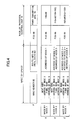
FIG. 3 is a flowchart of a routing packet generating process performed bynode 1.FIG. 4 illustrates a format of a routing packet P generated bynode 1 or by any ofnodes 2 through 4.FIG. 4 also illustrates examples of data items contained in the routing packet P generated by nodes 1 (X), 2 (Y), and 4 (z). - The process of
FIG. 3 is described with reference to a case where the transmittingwireless communications apparatus 100 generates the routing packet A for theroute including nodes FIG. 2 ) of theCPU 22 of the transmitting wireless communications apparatus 100 (node 1) generates aMAC header 62 in the RAM 20 (step S2). TheMAC header 62 generated at node 1 ("X") ofFIG. 4 includes the address of the next node (node 2) and the address of the final node 5 (receiving wireless communications apparatus 200). The "next node" may be an interposedwireless communications apparatus 50 or the receivingwireless communications apparatus 200. - The header/routing
info generating unit 132 of theCPU 22 then generatesroute information 64 in theRAM 20. Theroute information 64 is then attached to theMAC header 62. Theroute information 64 indicates a route from the node (node 1) that initially transmitted the routing packet to the current node. For example, theroute information 64 generated at node 1 (X) includes the address ofnode 1. Then, aFCS generating unit 87 of theprotocol control unit 18 calculates a FCS (frame check sequence) 68 (step S4). - Thus, the
MAC header 62 and theroute information 64 are generated by the header/routinginfo generating unit 132 of theCPU 22, while theFCS 68 is generated by theFCS generating unit 87 of theprotocol control unit 18. At this point, the packet does not yet include power consumption information. Such a packet prior to the addition of power consumption information may be referred to as "non-power-consumption-information-attached packet". Namely, the non-power-consumption-information-attached packet is generated by the header/routinginfo generating unit 132 of theCPU 22 and by theFCS generating unit 87 of theprotocol control unit 18. Thus, the header/routinginfo generating unit 132 and theFCS generating unit 87 may be collectively referred to as a "packet generating unit". The packet generating unit generates the non-power-consumption-information-attached packets for theroute including nodes route including nodes - Next, the
CPU 22 sets a transmission power in afirst register 88 of the protocol control unit 18 (step S6). TheCPU 22 of all nodes may retain a table 70 in advance. In the table 70, the adjacent nodes are associated with transmission power values for transmitting a packet to the adjacent nodes.FIG. 5 illustrates an example of the table 70, showing the transmission power required for transmitting a packet from the transmitting wireless communications apparatus 100 (node 1) to theadjacent nodes node 1 tonode 2 is -45 dBm. The transmission power required for transmitting a packet fromnode 1 tonode 3 is -30 dBm. - Thus, when the routing packet A is generated by
node 1, the corresponding transmission power is -45 dBm. Therefore, theCPU 22 sets the information in thefirst register 88 of theprotocol control unit 18, indicating that the transmission power is -45 dBm (step S6). Theprotocol control unit 18 sends the transmission power information stored in thefirst register 88 to theRF unit 14. The table 70 may be created by determining the transmission power for each node in accordance with the following equation:
- Next, an operating
unit 82 of theprotocol control unit 18 generates power consumption information for each route (step S8). The power consumption information indicates a value of power consumption involved in the transmission (or transfer) of the routing packet A to the adjacent node (node 2 in the present example). The power consumption information may be generated by various methods. In the following, two methods of generating the power consumption information from the transmission power information stored in thefirst register 88 are described. - In the first method, a converting
unit 822 in the operatingunit 82 and a table 80 are used. An example of the table 80 is illustrated inFIG. 6 , in which transmission power information and power consumption information are associated with each other. For example, when the transmission power is -50 dBm, the corresponding power consumption is 120 mW. The table 80 may be generated and stored in thetable storing unit 84 in advance. Because the transmission power for transmitting the packet fromnode 1 tonode 2 is -45 dBm, the convertingunit 822 converts the transmission power information (-45 dBm) to power consumption information indicating 130 mW by referring to the table 80. - In the second method, a calculating
unit 824 of the operatingunit 82 calculates power consumption information from the transmission power information in thefirst register 88 in accordance with a predetermined calculation formula. The predetermined calculation formula may be experimentally determined from transmission power values and power consumption values corresponding to the transmission power values in advance. The calculation formula may be retained in the calculatingunit 82. The power consumption information may be generated by other methods. - By using the first method that utilizes the table 80, calculation cost or processing load may be reduced. By using the second method involving a calculation formula, power consumption information corresponding to transmission power information that is not specified in the table 80 may be calculated. For example, the second method may enable the determination of an appropriate power consumption value when the exact transmission power, such as a value of -47 dBm, is not described in the table 80.
- The
MAC header 62 and theroute information 64 generated on theRAM 20 are transmitted to theprotocol control unit 18. In step S12 (FIG. 3 ), the attachingunit 86 attaches thepower consumption information 70 after theFCS 68. Namely, thepower consumption information 70 is included in the routing packet, thus obtaining the routing packet illustrated inFIG. 4 . The routing packet A is then transmitted to a baseband modulating/demodulating unit 16. The baseband modulating/demodulating unit 16 subjects the routing packet A to an OFDM (orthogonal frequency-division multiplexing) digital modulation process. After the OFDM process, the routing packet A is transmitted tonode 2 by atransceiver unit 12. -
FIG. 7 is a flowchart of a process flow between the interposed wireless communications apparatuses 50 (nodes 2 through 4) and the receiving wireless communications apparatus 200 (node 5). A flow of the routing packet is illustrated inFIG. 8 . The functional structure of thenodes 2 through 5 may be the same as illustrated inFIG. 2 . -
Node 1 transmits the routing packet A to node 2 (step S202 ofFIG. 8 ). Thetransceiver unit 12 ofnode 2 receives the routing packet A (step S101 ofFIG. 7 ). Thetransceiver unit 12 provides the received routing packet A to theRF unit 14. The routing packet A is thereafter stored in theRAM 20 via the baseband modulating/demodulating unit 16 and theprotocol control unit 18. - The analyzing
unit 128 of theCPU 22 analyzes theMAC header 62 contained in the routing packet A (step S102), and acquires the addresses ofnodes destination determining unit 126 of theCPU 22 determines whether the address of thefinal node 5 corresponds to the address of the current node, i.e., node 2 (step S104). Because the address of thefinal node 5 does not correspond to the address of node 2 (NO in S104), the process advances to step S106. - In step S106, a
rewriting unit 130 of theCPU 12 rewrites theMAC header 62 of the routing packet A stored in theRAM 20. Specifically, the address ofnode 2 shown in theMAC header 62 of the packet (X) inFIG. 4 is replaced with the address of the next node (node 4), as shown in theMAC header 62 generated by node 2 (Y). As a result, the routing packet A is transmitted fromnode 2 tonode 4. - Further, the
rewriting unit 130 ofnode 2 updates theroute information 64 by attaching the address ofnode 2. As a result of the updating, theroute information 64 indicates that the route is fromnode 1 tonode 2. For example, theroute information 64 is updated from "address ofnode 1 ", to, "address ofnode 1→address ofnode 2". Thereafter, theFCS generating unit 87 of theprotocol control unit 18 generates theFCS 68 in step S108. - The power
information acquiring unit 122 of theCPU 22 acquires thepower consumption information 70 in the routing packet A stored in theRAM 20. Thepower consumption information 70 is then stored in asecond register 90. - In step S110, as described above with reference to "Method of Generating a Routing Packet", the
CPU 22 sets transmission power information in thefirst register 88 of theprotocol control unit 18. The transmission power information indicates the amount of electric power required for wirelessly transmitting the routing packet A to the next node (node 4). The operatingunit 82 generates power consumption information based on the transmission power information stored in thefirst register 88. The power consumption information may be generated by various methods, such as the above-described first or the second method. For example, the power consumption for wireless transmission of the packet fromnode 2 tonode 4 may be 180 mW. - In step S112, an updating
unit 826 of the operatingunit 82 adds the power consumption value of 180 mW for wireless transmission fromnode 2 tonode 4 to the power consumption value of 130 mW stored in thefirst register 88. Then, the updatingunit 826 updates thepower consumption information 70 with the added result, i.e., a power consumption value of 310 mW. Thus, the operatingunit 82 of node 2 (interposed wireless communications apparatus) generates the power consumption information by summing the power consumption value generated from the transmission power required for transmitting the routing packet fromnode 1 tonode 2, and the power consumption value generated from the transmission power required for transmitting the packet fromnode 2 to node 4 (another interposed wireless communications apparatus) or node 5 (receiving wireless communications apparatus 200). - In step S114, the thus updated
power consumption information 70 is attached after theFCS 68 by the attachingunit 86, thus including thepower consumption information 70 in the routing packet A. The routing packet A with the updated power consumption information is then processed by the baseband modulating/demodulating unit 16, converted into a wireless signal by theRF unit 14, and then transmitted tonode 4 by the transceiver unit 12 (step S116 and step S204). - The processes of steps S101 through S116 are also performed by
node 4.Node 4 sets a power consumption value of 150 mW corresponding to the transmission power that is set for the transmission of the packet fromnode 4 tonode 5. The wireless communications apparatus ofnode 4 changes the "Next node" information in theMAC header 62 from the address ofnode 2 to the address ofnode 5, as illustrated inFIG. 4 (z) . Further, theroute information 64 is updated from "address ofnode 1 → address ofnode 2", with, "address ofnode 1→address ofnode 2→address ofnode 4". Also, thepower consumption information 70 is updated to 310+150=460 mW. - The routing packet A containing the information indicated by "z" in
FIG. 4 with the updated power consumption information and the like is transmitted to node 5 (receiving wireless communications apparatus 200). Total power consumption for transmitting the packet fromnode 1 tonode 5 is 460 mW. On the other hand, when the routing packet B is transmitted via the route ofnodes - Thus, the transceiver unit of an interposed
wireless communications apparatus 50 transfers the routing packet to the next interposedwireless communications apparatus 50 or the receivingwireless communications apparatus 200. - A process performed by the receiving wireless communications apparatus 200 (node 5) is described with reference to the flowchart of
FIG. 7 . In step S101, the receivingwireless communications apparatus 200 receives the routing packets A and B fromnode 4. The routing packets A and B are stored in theRAM 20 via theRF unit 14, the baseband modulating/demodulating unit 16, and theprotocol control unit 18. In step S102, theMAC header 62 of the routing packets A and B is analyzed by the analyzingunit 128 of theCPU 22. - In step S104, the analyzing
unit 128 of theCPU 22 determines whether the final node address in theMAC header 62 corresponds to the address ofnode 5. Because the final node address in theMAC header 62 is the address of node 5 (YES in step S104), the process advances to step S118. - In step S118, the receiving
wireless communications apparatus 200 stands by for a duration of time (step S118 and step S208) in order to receive all of the routing packets for all routes. Thereafter, the powerinformation acquiring unit 122 of theCPU 22 acquires the power consumption information for the routes (the route ofnodes nodes information acquiring unit 122 acquires the power consumption information (=460 mW) attached to the routing packet A and the power consumption information (=400 mW) attached to the routing packet B. - In step S120, the
decision unit 124 determines the routing packet having the minimum power consumption by comparing the power consumption information acquired from the routing packets A and B by the powerinformation acquiring unit 122. - For example, the power consumption information attached to the routing packet A indicates 460 mW, while the power consumption information attached to the routing packet B indicates 400 mW. Thus, the
decision unit 124 selects the routing packet B as the routing packet having the minimum power consumption. Thedecision unit 124 therefore determines that the route corresponding to the routing packet B - (
nodes - In step S126, the protocol control unit 8 creates a route-determination packet indicating that the route has been selected. The route-determination packet is used for notifying the interposed wireless communications apparatuses in the selected route. In step S128, the
transceiver unit 2 transmits the route-determination packet. - The route-determination packet is transferred back to
node 1 via the selected route, i.e., vianodes transceiver unit 2 ofnode 4 transfers the route-determination packet to node 3 (steps S212 through S216). -
FIG. 9 is a flowchart of a real data transmit process in which real data (such as image data) is transmitted bynode 1 via the route determined by the above-described route-determining process. The flow ofFIG. 9 is similar to the flow ofFIG. 3 with the exception that steps S6, S8, and S12 of the latter are omitted. - In step S902, the
CPU 22 creates theMAC header 62. Alternatively, theMAC header 62 created in the route-determining process and then stored in theRAM 20 may be used in this step. In step S904, theCPU 22 attaches real data (image data) to the MAC header and calculates a FCS (frame check sequence). In step S906, the FCS is attached to the real data, thus generating a real data packet. The packet is transmitted by thetransceiver unit 12. - In step S218, the transmitting wireless communications apparatus 100 (node 1) transmits the real data packet to
node 3 from whichnode 1 received the route-determination packet. In step S220,node 3 transmits the received real data packet tonode 4 from whichnode 3 received the route-determination packet. In step S222,node 4 transmits the received real data packet tonode 5 from whichnode 4 received the route-determination packet. In this way, node 5 (receiving wireless communications apparatus 200) receives the image data from the transmitting wireless communications apparatus 100 (node 1). In step S224,node 5 transmits an ACK signal tonode 4, indicating a safe reception of the real data packet. In step S226,node 4 transfers the ACK signal received fromnode 5 tonode 3 from whichnode 4 received the real data packet. In step S228,node 3 transfers the ACK signal received fromnode 4 tonode 1 that transmitted the real data packet. By receiving the ACK signal,node 1 recognizes that the real data packet has been safely received bynode 5. - Thus, in accordance the present embodiment, a route with the minimum power consumption can be determined from a plurality of routes, and the transmitting
wireless communications apparatus 100 can transmit real data, such as image data, via the determined route. Thus, consumption of power required for transmitting real data can be minimized. - The operating
unit 82 may convert transmission power information into power consumption information for the following reason. The transmission power information is determined by equation (1). Transmission power is not dependent on the type of thetransceiver unit 12 of the interposed wireless communications apparatus. Transmission power may not be dependent on the type of an antenna of the interposed wireless communications apparatus. - On the other hand, power consumption is dependent on the type of the
transceiver unit 12 of the interposed wireless communications apparatus. Thus, power consumption information can be appropriately determined by the operatingunit 82 even if the type of the transmitting wireless communications apparatus is changed. - The power consumption information may be attached at the end of the routing packet as illustrated in
FIG. 4 for the following reason. In accordance with the present embodiment, all of the interposedwireless communications apparatuses 50 in the network are capable of processing the power consumption information. However, if one or more of the interposed wireless communications apparatuses are not capable of processing the power consumption information, and if the power consumption information is attached at a location other than at the end of the routing packet (such as next to the MAC header 62), the power consumption information cannot be processed, resulting in an error in the one or more wireless communications apparatuses. - By attaching the power consumption information at the end of the routing packet, the interposed
wireless communications apparatus 50 that is not capable of processing power consumption information can perform a process by deleting the power consumption information. Thus, no error is caused in the interposedwireless communications apparatuses 50 not capable of processing power consumption information in a network. -
FIG. 10 illustrates anetwork having routes 1, ..., m, ..., and M, where M is an integer of 3 or more. Each of the routes includes n1, ... , nm, ... , nM interposedwireless communications apparatuses 50. Hereafter, the m-th interposedwireless communications apparatus 50 in the route m is designated as "50mnm" or "node mnm". - The packet generating unit (header/routing
info generating unit 132 andFCS generating unit 87 inFIG. 2 ) of the transmittingwireless communications apparatus 100 generates routing packets Pm(1,...,m,...,M) for each of the M routes (in steps S2 and S4 inFIG. 3 ). Thus, the packet generating unit generates M packets. - After step S6 (
FIG. 3 ), the operatingunit 82 of the transmittingwireless communications apparatus 100 generates power consumption information 70m for each of the M routes, indicating the amount of power consumed by transmitting the packet to the nextwireless communications apparatus 50. The routing packet Pm to which the power consumption information 70m is attached is transmitted by thetransceiver unit 2. - Next, a process performed by the interposed wireless communications apparatus 50mnm (node mnm) after steps S106, S108, and S110 in
FIG. 7 is described. In step S112, a total of power consumed by the transmission of the routing packet Pm fromnode 1 to node mnm is stored in thesecond register 90. Then, node mnm determines the power consumption for transmitting the routing packet Pm to the next node mnm+1. The thus determined power consumption is added by the updatingunit 826 to the power consumption value stored in the second register, thereby updating thepower consumption information 70 of the routing packet Pm. The subsequent process is similar to the process of steps S114 and S116 and is therefore not described herein. - Thus, when the packet is transmitted from
node 1 to node Q via any one of theroutes 1, ..., m, ..., and M, each of the interposed wireless communications apparatuses successively adds a power consumption value. Namely, the updatingunit 826 of each interposed wireless communications apparatus (seeFIG. 2 ) adds the value of power consumption by the previous transmission of the routing packet to the power consumption for transmitting the routing packet to the next interposed wireless communications apparatus or the receiving wireless communications apparatus. - In accordance with the present embodiment, the transmitting
wireless communications apparatus 100, the receivingwireless communications apparatus 200, and the interposedwireless communications apparatuses 50 include all of the functional units illustrated inFIG. 2 . Alternatively, one or more of the nodes may not include all of the illustrated functional units as needed. - In accordance with an embodiment, the transmitting wireless communications apparatus 100 (node 1) may be configured to broadcast the routing packet including the power consumption information. Transmission power used for calculating the power consumption information may be set between the transmitting
wireless communications apparatus 100 and one of the interposed wireless communications apparatuses that can wirelessly communicate with the transmittingwireless communications apparatus 100. - The interposed wireless communications apparatuses (
nodes 2 and 3) that received the routing packet via broadcasting may then broadcast the routing packet. When broadcasting the routing packet, the interposed wireless communications apparatuses (nodes 2 and 3) each adds to the power consumption information in the routing packet a power consumption value calculated by using a transmission power value that is set between the interposed wireless communications apparatus (nodes 2 and 3) and one of the other interposed wireless communications apparatuses that can wirelessly communicate withnodes - The interposed wireless communications apparatus (node 4) that received the routing packet broadcast by the interposed wireless communications apparatuses (
nodes 2 and 3) broadcasts the routing packet. When broadcasting the routing packet, the interposed wireless communications apparatus (node 4) adds to the power consumption information in the routing packet a power consumption value calculated by using a transmission power value set between the wireless communications apparatus (node 4) and one of the other interposed wireless communications apparatuses that can wirelessly communicate with the wireless communications apparatus (node 4) or the receiving wireless communications apparatus. - The receiving
wireless communications apparatus 200 receives the routing packet broadcast by the interposed wireless communications apparatus (node 4). The receivingwireless communications apparatus 200 determines a route based on the received routing packet. For example, the route may be determined based on the power consumption information in the routing packet, such that the power consumption can be minimized. The receivingwireless communications apparatus 200 then transmits a route-determination packet including the route information determined based on the routing packet. The route-determination packet is transferred between the interposed wireless communications apparatuses included in the route information and eventually received by the transmittingwireless communications apparatus 100. -
FIG. 11 is a block diagram of a hardware structure of the transmittingwireless communications apparatus 100, the receivingwireless communications apparatus 200, or thewireless communications apparatus 50 according to the present embodiment. - The structure includes a
CPU 22, aRAM 20, aROM 24, a network I/F unit 516, aninput unit 517, adisplay unit 518, and an external storage I/F unit 514. - The
CPU 22 is an operating unit configured to control the various units of the apparatus or a computer and perform various data operations or processes. TheCPU 22 may be configured to perform a process in accordance with a program stored in theRAM 20. TheCPU 22 may receive data from an input unit or a storage unit, operate or process the data, and then output resultant data to an output unit or the storage unit. - The
RAM 20 is a storage unit in which an OS (operating system) or an application software program executed by theCPU 22 and various data may be saved or temporarily stored. TheROM 24 is another storage unit in which data related to the application software may be stored. - The network I/
F unit 516 provides an interface for enabling communication with a network such as a LAN (Local Area Network) or a WAN (Wide Area Network) which may be set up using wired or wireless data transmission routes. Thus, the network I/F unit 516 enables communications with other wireless communications apparatuses or the like. - The
input unit 517 and thedisplay unit 518 may include an LCD (Liquid Crystal Display) having key switches (hardware keys) and a touch panel function. The touch panel function may include software keys for a graphical user interface (GUI). Theinput unit 517 and thedisplay unit 518 may include a display/input unit configured to provide a user interface (UI) when a user utilizes a function of the wireless communications apparatus. - The external storage I/
F unit 514 provides an interface with a recording medium 515 (such as a flash memory) which may be connected to the wireless communications apparatus via a data transmission route such as a USB (Universal Serial Bus) cable. - A program stored in the
recording medium 515 may be installed in thewireless communications apparatus F unit 514, so that the installed program can be executed by the wireless communications apparatus, which may include a PC. -
FIG. 12 illustrates a meshnetwork including nodes 1 through 5 (wireless communications apparatuses). Initially, the route passing throughnodes - In the example of
FIG. 12 ,node 3 has been moved away fromnodes node 1 tonode 3 and fromnode 3 tonode 4. As a result, power consumption increases. Thus, it is more preferable to select another route that requires lower power consumption than continue with the current route having the increased power consumption. -
FIG. 13 illustrates an example in which a wireless communications apparatus in a selected route is replaced with another wireless communications apparatus. At the time of route setting, the selected route may includenode 3. The route may be determined by transmitting a routing packet and acquiring power consumption information contained in the route-determination packet. For example, the route vianodes FIG. 13 , the route that has been originally set includednode 3. However, becausenode 3 became unable to communicate after the route setting,node 6 is used instead for transferring data fromnode 1 tonode 4, thus modifying the route. When transmission of the real data is continued with the modified route, power consumption may increase. - When
node 6 is included in the route, the transmission power that is set for transmitting the real data as calculated in accordance with equation (1) may increase for transmitting the real data both fromnode 1 tonode 6 and fromnode 6 tonode 4. When the transmission power thus increases, the power consumption also increases. - Thus, in accordance with the present embodiment, each wireless communications apparatus attaches power consumption information to the real data that is transmitted after the route setting when transmitting the real data. The receiving
wireless communications apparatus 200 determines whether to request routing (route-determining process) by the transmittingwireless communications apparatus 100 based on the power consumption information contained in the received real data. -
FIG. 14 is a block diagram of the wireless communications apparatus according to the present embodiment. The wireless communications apparatus is similar to the apparatus ofFIG. 2 with the exception that a powerconsumption determination unit 134 and arouting requesting unit 136 are additionally provided. - When the wireless communications apparatus is the receiving
wireless communications apparatus 200, the powerconsumption determination unit 134 determines whether routing should be performed based on the power consumption information contained in the real data packet received from an interposed wireless communications apparatus. For example, the powerconsumption determination unit 134 retains power consumption information ("reference power consumption") when a route to be used is determined based on the routing packet. Upon reception of real data from the interposed wireless communications apparatus, the powerconsumption determination unit 134 determines whether the power consumption information contained in the real data is greater than the reference power consumption. The reference power consumption may include a margin so that routing (route-determining process) is not conducted too frequently. For example, when the amount of movement of the node is small, the power consumption may not be changed much from the reference power consumption. Similarly, when the wireless communications apparatus that is rendered incapable of performing communications is replaced with a nearby wireless communications apparatus for relaying data, the power consumption may not be changed much from the reference power consumption. - When the power consumption information value contained in the real data is greater than the reference power consumption, the power
consumption determination unit 134 determines that routing should be conducted because the power consumption by the network as a whole can be expected to increase. The reference power consumption may include a margin, as mentioned above. On the other hand, when the power consumption value contained in the real data is equal to or less than the reference power consumption which may include a margin, the powerconsumption determination unit 134 may determine that routing should not be conducted because the power consumption of the network as a whole is not increased. Upon determining that routing should be conducted, the powerconsumption determination unit 134 instructs therouting requesting unit 136 to conduct the route-determination process. - The
routing requesting unit 136, upon reception of a routing instruction from the powerconsumption determination unit 134, requests routing packets from the transmittingwireless communications apparatus 100. For example, therouting requesting unit 136 is configured to transmit a packet for requesting the transmission of the routing packets. - Upon reception of the packet requesting the transmission of the routing packets from the receiving
wireless communications apparatus 200, the transmittingwireless communications apparatus 100 transmits the routing packets. Based on the routing packets, a route that would minimize power consumption is set. -
FIG. 15 is a flowchart of an operation of the transmittingwireless communications apparatus 100 according to the present embodiment. In step S1502, the header/routinginfo generating unit 132 of theCPU 22 generates theMAC header 62 on theRAM 20. TheMAC header 62 includes the address of the next node, as described above with reference toFIG. 4 . TheMAC header 62 may also include the address of the final node (receiving wireless communications apparatus 200). The "next node" refers to one or more of the interposed wireless communications apparatuses capable of communicating with the current node that are included in the route that has been set, or the receiving wireless communications apparatus. - The header/routing
info generating unit 132 of theCPU 22 generatesreal data 66 on theRAM 20 and adds thereal data 66 to theMAC header 62. Next, in step S1504, theFCS generating unit 87 of theprotocol control unit 18 calculates theFCS 68. In step S1504, the header/routinginfo generating unit 132 of theCPU 22 generates theMAC header 62 and thereal data 66. TheFCS generating unit 87 of theprotocol control unit 18 generates theFCS 68. - In step S1506, the
CPU 22 sets a transmission power value in thefirst register 88 of theprotocol control unit 18. Theprotocol control unit 18 then notifies theRF unit 14 of the transmission power value stored in thefirst register 88. In step S1508, the operatingunit 82 of theprotocol control unit 18 generates power consumption information to be attached to thereal data 66 that is to be relayed to the next node. The operatingunit 82 may generate the power consumption information by the above-described first and/or the second method. - The
MAC header 62 and thereal data 66 generated on theRAM 20 are transmitted to theprotocol control unit 18. In step S1510, the attachingunit 86 attaches thepower consumption information 70 after theFCS 68. Namely, thepower consumption information 70 is included in the real data packet, which is then transmitted to the baseband modulating/demodulating unit 16. The baseband modulating/demodulating unit 16 subjects the real data packet to an OFDM (orthogonal frequency-division multiplexing digital modulation) process. Thereafter, the routing packet A is transmitted by thetransceiver unit 12 in step S1512. -
FIG. 16 is a flowchart of an operation of the interposedwireless communications apparatus 50 and the transmittingwireless communications apparatus 100. In step S1602, the interposedwireless communications apparatus 50 receives the real data packet from the transmittingwireless communications apparatus 100 via thetransceiver unit 12. The real data packet is then fed to theRF unit 14. The real data packet is then stored in theRAM 20 via the baseband modulating/demodulating unit 16 and theprotocol control unit 18. - In step S1604, the analyzing
unit 128 of theCPU 22 analyzes theMAC header 62 contained in the real data packet. In step S1606, thedestination determining unit 126 of theCPU 22 determines whether the address of the final node corresponds to the address of the interposedwireless communications apparatus 50. - If the address of the final node does not correspond to the address of the interposed wireless communications apparatus 50 (NO in step S1606), the power
information acquiring unit 122 of theCPU 22 acquires thepower consumption information 70 in the real data packet stored in theRAM 20, and stores thepower consumption information 70 in thesecond register 90. - In step S1610, the
CPU 22 sets a transmission power value in thefirst register 88 within theprotocol control unit 18. The transmission power value is the electric power required for wirelessly transmitting the real data packet to the next node. The operatingunit 82 generates power consumption information based on the transmission power information stored in thefirst register 88. The power consumption information may be generated by the above-described first or second method. - The updating
unit 826 of the operatingunit 82 adds the power consumption value generated by the operatingunit 82 to the power consumption value stored in thesecond register 90. The updatingunit 826 then updates thepower consumption information 70 with the calculated value of power consumption (step S1612). In other words, the operatingunit 82 of the interposed wireless communications apparatus generates the power consumption information by adding the power consumption value generated from the transmission power required for transmitting the real data packet from the transmittingwireless communications apparatus 100 to the interposed wireless communications apparatus, to the power consumption value generated from the transmission power required for transmission of the real data packet from the interposed wireless communications apparatus to the next interposed wireless communications apparatus or the receiving wireless communications apparatus. - In step S1614, the attaching
unit 86 attaches the updatedpower consumption information 70 after theFCS 68. Namely, thepower consumption information 70 is included in the real data packet. The real data packet to which the updated power consumption information is attached is processed by the baseband modulating/demodulating unit 16, converted into a wireless signal by theRF unit 14, and then transmitted by the transceiver unit 12 (step S1616). - If it is determined in step S1606 that the address of the final node corresponds to the address of the intermediate wireless communications apparatus (YES in step S1606), the power
consumption determination unit 134 of theCPU 22 determines whether the power consumption value contained in the real data packet is increased over the power consumption value at the time of initial route setting (step S1608). If the power consumption value contained in the real data packet is increased over the power consumption value at the time of initial route setting (YES in step S1618), the powerconsumption determination unit 134 determines that a routing request should be made. Specifically, the powerconsumption determination unit 134 instructs therouting requesting unit 136 to send a routing request to the transmittingwireless communications apparatus 100. Upon reception of the routing request instruction from the powerconsumption determination unit 134, therouting requesting unit 136 of theCPU 22 transmits a routing requesting packet to the transmittingwireless communications apparatus 100. - On the other hand, if it is determined in step S1618 that the power consumption value contained in the real data packet is not more than the power consumption at the time of initial route setting (NO in step S1618), the process returns to step S1602 because the power consumption has not increased and there is no need for additional routing.
- In accordance with the present embodiment, the value of the reference power consumption may be set by a user. In this way, it can be determined whether routing should be conducted in accordance with user requests. For example, when it is desired to reduce power consumption even if routing is conducted very frequently, the reference power consumption value may be set to a low value. Conversely, when it is desired to reduce the time required for routing even if power consumption is increased somewhat, the reference power consumption value may be set to a high value. Thus, the reference power consumption value can be set to an appropriate value depending on the environment in which the wireless communications apparatus is used, so that an appropriate route can be selected.
- In accordance with the present embodiment, the wireless communications apparatus may include a display unit for displaying power consumption information. The display unit allows the user to monitor power consumption, thereby facilitating the management of the network. For example, the number of the wireless communications apparatuses in a network can be increased or decreased depending on the amount of power consumption.
- The wireless communications apparatus may also include a notifying unit for issuing a notification when it is determined that a routing is to be conducted. Further, the wireless communications apparatus may include a routing initiating unit for initiating the routing process. For example, in response to the notification that a routing is to be conducted, a user may or may not instruct the routing initiating unit to initiate a routing.
- Although this invention has been described in detail with reference to certain embodiments, variations and modifications exist within the scope and spirit of the invention as described and defined in the following claims.
Claims (15)
- A wireless communications apparatus in a network of a plurality of wireless communications apparatuses connected by a plurality of routes,
the apparatus comprising:a packet generating unit configured to generate a packet for each of the plurality of routes in the network;an operating unit configured to generate power consumption information for each of the routes, the power consumption information indicating power consumption for transmitting the corresponding packets;an attaching unit configured to attach the power consumption information to the packets; anda transmit unit configured to transmit the packets to which the power consumption information is attached via the corresponding routes. - The wireless communications apparatus according to claim 1, wherein the operating unit generates the power consumption information based on transmission power information for transmitting the packets.
- The wireless communications apparatus according to claim 1 or 2, wherein the attaching unit attaches the power consumption information at the end of the packets.
- A wireless communications apparatus in a network of a plurality of wireless communications apparatuses connected by a plurality of routes,
the apparatus comprising:a receiving unit configured to receive a packet to which power consumption information is attached, the power consumption information indicating power consumption for transferring the packet in the network;an acquiring unit configured to acquire the power consumption information attached to the packet received by the receiving unit; anda decision unit configured to determine one of the plurality of routes that has the minimum power consumption by comparing the power consumption information acquired by the acquiring unit regarding the one route with that of another of the routes in the network. - The wireless communications apparatus according to claim 4, further comprising:a power consumption determination unit configured to determine whether the power consumption indicated by the power consumption information acquired by the acquiring unit is greater than a predetermined threshold value; anda routing requesting unit configured to request one of the wireless communications apparatuses that transmitted the packet to perform a routing process when the power consumption determination unit determines that the power consumption indicated by the power consumption information is greater than the predetermined threshold value.
- The wireless communications apparatus according to claim 5, wherein the predetermined threshold value is associated with the power consumption corresponding to the route determined by the decision unit.
- The wireless communications apparatus according to claim 5 or 6, further comprising:a notifying unit configured to notify a user about the routing process requested by the routing requesting unit.
- The wireless communications apparatus according to any one of claims 4 through 7, further comprising a display unit configured to display the power consumption information acquired by the acquiring unit.
- A network communications system having a transmitting wireless communications apparatus, a receiving wireless communications apparatus, and a plurality of interposed wireless communications apparatuses;
wherein the transmitting communications apparatus includes:a packet generating unit configured to generate a packet for each of a plurality of routes in the network;an operating unit configured to generate power consumption information for each of the routes, the power consumption information indicating power consumption for transmitting the packets;an attaching unit configured to attach the power consumption information to the packets; anda transmit unit configured to transmit the packets to which the power consumption information is attached via the corresponding routes, andthe receiving wireless communications apparatus includesa receiving unit configured to receive the packets to which power consumption information is attached, the power consumption information indicating power consumption for transferring the corresponding packets in the network;an acquiring unit configured to acquire the power consumption information attached to the packets received by the receiving unit; anda decision unit configured to determine one of the plurality of routes that has the minimum power consumption by comparing the power consumption information acquired by the acquiring unit regarding the one of the routes with that of another of the routes in the network. - A network communications system having a transmitting wireless communications apparatus comprising a wireless communications apparats in accordance with any one of claims 1 to 3 and a wireless communications apparatus in accordance with any one of claims 4 to 8.
- The network communications system according to claim 9, the receiving wireless communications apparatus further comprising:a power consumption determination unit configured to determine whether the power consumption indicated by the power consumption information acquired by the acquiring unit is greater than a predetermined threshold value; anda routing requesting unit configured to request one of the wireless communications apparatuses that transmitted the packets to perform a routing process when the power consumption determination unit determines that the power consumption indicated by the power consumption information is greater than the predetermined threshold value.
- A communications method for a network having a transmitting wireless communications apparatus, a receiving wireless communications apparatus, and a plurality of interposed wireless communications apparatuses,
the method comprising:generating a packet in the transmitting wireless communications apparatus for each of a plurality of routes of the network;generating power consumption information for each of the routes, the power consumption information indicating power consumption by the transmitting wireless communications apparatus for transmitting the packets;attaching the power consumption information to the packets;transmitting the packets to which the power consumption information is attached from the transmitting wireless communications apparatus via the corresponding routes;receiving by the receiving wireless communications apparatus the packets transmitted in the transmitting step to which other power consumption information is attached,the other power consumption information indicating power consumption by transferring of the packets in the network;acquiring the power consumption information attached to the received packets in the receiving wireless communications apparatus; anddetermining in the receiving wireless communications apparatus one of the plurality of routes in the network that has the minimum power consumption by comparing the power consumption information of one of the routes with that of another of the routes. - The communications method according to claim 12, further comprising:determining whether the power consumption indicated by the power consumption information acquired in the acquiring step is greater than a predetermined threshold value; andrequesting a routing process from the wireless communications apparatus that transmitted the packets when it is determined in the determining step that the power consumption indicated by the power consumption information is greater than the predetermined threshold value.
- A computer-readable program for causing a computer to perform as the wireless communications apparatus according to any one of claims 1 through 8.
- A non-transitory computer-readable recording medium in which the program of claim 14 is recorded.
Applications Claiming Priority (2)
| Application Number | Priority Date | Filing Date | Title |
|---|---|---|---|
| JP2009262237 | 2009-11-17 | ||
| JP2010138332A JP5560941B2 (en) | 2009-11-17 | 2010-06-17 | Wireless communication apparatus, wireless communication system, wireless communication method, wireless communication program, and recording medium |
Publications (2)
| Publication Number | Publication Date |
|---|---|
| EP2323440A1 true EP2323440A1 (en) | 2011-05-18 |
| EP2323440B1 EP2323440B1 (en) | 2013-01-23 |
Family
ID=43608684
Family Applications (1)
| Application Number | Title | Priority Date | Filing Date |
|---|---|---|---|
| EP20100251943 Not-in-force EP2323440B1 (en) | 2009-11-17 | 2010-11-17 | Method, apparatus and system for reducing power consumption in a mesh network |
Country Status (3)
| Country | Link |
|---|---|
| US (1) | US8599743B2 (en) |
| EP (1) | EP2323440B1 (en) |
| JP (1) | JP5560941B2 (en) |
Cited By (4)
| Publication number | Priority date | Publication date | Assignee | Title |
|---|---|---|---|---|
| WO2013181754A1 (en) | 2012-06-07 | 2013-12-12 | Alcatel Lucent | Oam power packet |
| WO2015090348A1 (en) * | 2013-12-16 | 2015-06-25 | Telefonaktiebolaget L M Ericsson (Publ) | Method and apparatus for data packet transmission |
| US9237506B2 (en) | 2011-07-29 | 2016-01-12 | Texecom Limited | Method for improving performance and reducing power consumption of a wireless network arrangement |
| EP4106406A1 (en) * | 2021-06-18 | 2022-12-21 | Deutsche Telekom AG | Method for the routing of data packets, among a plurality of network nodes of a telecommunications network, while taking into account energy intensity regarding the transmission of such data packets, telecommunications network or network node, program, and computer-readable medium |
Families Citing this family (6)
| Publication number | Priority date | Publication date | Assignee | Title |
|---|---|---|---|---|
| JP2013135450A (en) * | 2011-12-27 | 2013-07-08 | Fujitsu Ltd | Network control method, network system and transfer device |
| JP6128365B2 (en) * | 2012-06-18 | 2017-05-17 | 沖電気工業株式会社 | Wireless communication terminal, wireless network system, and transmission power control method and program |
| US9025461B2 (en) * | 2012-08-01 | 2015-05-05 | Qualcomm Incorporated | Power optimized behavior in mesh networks |
| EP2941054A4 (en) * | 2012-12-26 | 2016-03-30 | Fujitsu Ltd | Information processing method, communication method, communication nodes, system, and information processing program |
| CN109514633B (en) * | 2018-11-07 | 2021-06-15 | 太仓新绿杰实业有限公司 | Honeycomb paperboard cutting device |
| CN114979826B (en) * | 2022-05-16 | 2023-01-10 | 北京智芯微电子科技有限公司 | Power consumption control method, system, equipment and chip of multimode communication equipment |
Citations (5)
| Publication number | Priority date | Publication date | Assignee | Title |
|---|---|---|---|---|
| WO2002041521A2 (en) * | 2000-11-07 | 2002-05-23 | Hrl Laboratories, Llc | Power management for throughput enhancement in wireless ad-hoc networks |
| EP1341346A2 (en) * | 2002-03-01 | 2003-09-03 | NTT DoCoMo, Inc. | Wireless communication system for multi-hop connection, source station, radio station and pilot signal used therein |
| JP2007074564A (en) | 2005-09-08 | 2007-03-22 | Oki Electric Ind Co Ltd | Network routing method and radio station |
| US20080010385A1 (en) * | 2006-03-28 | 2008-01-10 | Samsung Electronics Co., Ltd | Routing method in consideration of power and transmission delay in wireless ad hoc network and terminal device adopting the same |
| JP2008219526A (en) | 2007-03-05 | 2008-09-18 | Univ Of Electro-Communications | Radio terminal |
Family Cites Families (19)
| Publication number | Priority date | Publication date | Assignee | Title |
|---|---|---|---|---|
| US6700964B2 (en) * | 2001-07-23 | 2004-03-02 | Securelogix Corporation | Encapsulation, compression and encryption of PCM data |
| US6697337B1 (en) * | 2001-09-17 | 2004-02-24 | Networks Associates Technology, Inc. | Method and apparatus for capture, analysis and display of packet information sent in an IEEE 802.11 wireless network |
| GB0220660D0 (en) * | 2002-09-05 | 2002-10-16 | Nokia Corp | Signal propogation delay routing |
| AU2002357353A1 (en) * | 2002-12-20 | 2004-07-22 | International Business Machines Corporation | Maximum lifetime routing in wireless ad-hoc networks |
| CA2491747A1 (en) * | 2003-05-06 | 2004-11-18 | Samsung Electronics Co., Ltd. | Route discovery device and method in a mobile ad-hoc network |
| WO2004114690A1 (en) * | 2003-06-05 | 2004-12-29 | Meshnetworks, Inc. | Optimal routing in ad hac wireless communication network |
| US20060185013A1 (en) * | 2003-06-18 | 2006-08-17 | Telefonaktiebolaget Lm Ericsson (Publ) | Method, system and apparatus to support hierarchical mobile ip services |
| KR100605745B1 (en) * | 2004-01-06 | 2006-07-31 | 삼성전자주식회사 | Determination apparatus and method path for data transmission in mobile communication system which consist of nodes |
| JP2006237849A (en) * | 2005-02-23 | 2006-09-07 | Sharp Corp | Communication system and data transmitter |
| US7630326B1 (en) * | 2005-03-11 | 2009-12-08 | Dust Networks, Inc. | Application-driven agile networks |
| US7684337B2 (en) * | 2006-01-17 | 2010-03-23 | Mitsubishi Electric Research Laboratories, Inc. | Method and system for communicating in cooperative relay networks |
| DE602006001201D1 (en) * | 2006-03-13 | 2008-06-26 | Ntt Docomo Inc | Method and device for controlling the transmission of data from multiple sensor nodes |
| US8059578B2 (en) * | 2006-07-24 | 2011-11-15 | Harris Corporation | System and method for synchronizing TDMA mesh networks |
| JP5230918B2 (en) | 2006-09-04 | 2013-07-10 | 三菱電機株式会社 | Wireless multi-hop communication device and communication method |
| JP2009011803A (en) | 2007-06-06 | 2009-01-22 | Hirata Seiki:Kk | Forceps for endoscopic surgical operation |
| JP5019965B2 (en) | 2007-06-15 | 2012-09-05 | 株式会社リコー | Image processing device, expansion board, and electrical equipment |
| US20090010189A1 (en) * | 2007-07-07 | 2009-01-08 | Nagra Sundeep S | Network with remaining battery life routing metric |
| US7944899B2 (en) * | 2007-08-15 | 2011-05-17 | Oracle America, Inc. | Predictive routing technique in the ad hoc wireless network |
| JP4954096B2 (en) * | 2008-01-10 | 2012-06-13 | 株式会社リコー | COMMUNICATION DEVICE, COMMUNICATION METHOD, PROGRAM, AND COMPUTER-READABLE RECORDING MEDIUM |
-
2010
- 2010-06-17 JP JP2010138332A patent/JP5560941B2/en not_active Expired - Fee Related
- 2010-11-15 US US12/946,038 patent/US8599743B2/en not_active Expired - Fee Related
- 2010-11-17 EP EP20100251943 patent/EP2323440B1/en not_active Not-in-force
Patent Citations (5)
| Publication number | Priority date | Publication date | Assignee | Title |
|---|---|---|---|---|
| WO2002041521A2 (en) * | 2000-11-07 | 2002-05-23 | Hrl Laboratories, Llc | Power management for throughput enhancement in wireless ad-hoc networks |
| EP1341346A2 (en) * | 2002-03-01 | 2003-09-03 | NTT DoCoMo, Inc. | Wireless communication system for multi-hop connection, source station, radio station and pilot signal used therein |
| JP2007074564A (en) | 2005-09-08 | 2007-03-22 | Oki Electric Ind Co Ltd | Network routing method and radio station |
| US20080010385A1 (en) * | 2006-03-28 | 2008-01-10 | Samsung Electronics Co., Ltd | Routing method in consideration of power and transmission delay in wireless ad hoc network and terminal device adopting the same |
| JP2008219526A (en) | 2007-03-05 | 2008-09-18 | Univ Of Electro-Communications | Radio terminal |
Non-Patent Citations (1)
| Title |
|---|
| TSUDAKA K ET AL: "Power control routing for multi hop wireless ad-hoc network", GLOBECOM'01. 2001 IEEE GLOBAL TELECOMMUNICATIONS CONFERENCE. SAN ANTONIO, TX, NOV. 25 - 29, 2001; [IEEE GLOBAL TELECOMMUNICATIONS CONFERENCE], NEW YORK, NY : IEEE, US, vol. 5, 25 November 2001 (2001-11-25), pages 2819 - 2824, XP010747553, ISBN: 978-0-7803-7206-1, DOI: 10.1109/GLOCOM.2001.965944 * |
Cited By (10)
| Publication number | Priority date | Publication date | Assignee | Title |
|---|---|---|---|---|
| US9237506B2 (en) | 2011-07-29 | 2016-01-12 | Texecom Limited | Method for improving performance and reducing power consumption of a wireless network arrangement |
| WO2013181754A1 (en) | 2012-06-07 | 2013-12-12 | Alcatel Lucent | Oam power packet |
| CN104350706A (en) * | 2012-06-07 | 2015-02-11 | 阿尔卡特朗讯公司 | Oam power packet |
| EP2859687A4 (en) * | 2012-06-07 | 2016-02-17 | Alcatel Lucent | Oam power packet |
| CN104350706B (en) * | 2012-06-07 | 2018-04-13 | 阿尔卡特朗讯公司 | OAM power is grouped |
| WO2015090348A1 (en) * | 2013-12-16 | 2015-06-25 | Telefonaktiebolaget L M Ericsson (Publ) | Method and apparatus for data packet transmission |
| EP3085160B1 (en) * | 2013-12-16 | 2018-07-04 | Telefonaktiebolaget LM Ericsson (publ) | Method and apparatus for data packet transmission |
| US10178599B2 (en) | 2013-12-16 | 2019-01-08 | Telefonaktiebolaget Lm Ericsson (Publ) | Method and apparatus for data packet transmission |
| EP4106406A1 (en) * | 2021-06-18 | 2022-12-21 | Deutsche Telekom AG | Method for the routing of data packets, among a plurality of network nodes of a telecommunications network, while taking into account energy intensity regarding the transmission of such data packets, telecommunications network or network node, program, and computer-readable medium |
| WO2022263194A1 (en) * | 2021-06-18 | 2022-12-22 | Deutsche Telekom Ag | Method for the routing of data packets, among a plurality of network nodes of a telecommunications network, while taking into account energy intensity regarding the transmission of such data packets, telecommunications network or network node, program, and computer-readable medium |
Also Published As
| Publication number | Publication date |
|---|---|
| JP2011130406A (en) | 2011-06-30 |
| JP5560941B2 (en) | 2014-07-30 |
| EP2323440B1 (en) | 2013-01-23 |
| US20110116402A1 (en) | 2011-05-19 |
| US8599743B2 (en) | 2013-12-03 |
Similar Documents
| Publication | Publication Date | Title |
|---|---|---|
| EP2323440B1 (en) | Method, apparatus and system for reducing power consumption in a mesh network | |
| CN108028802B (en) | Construction of self-organizing mesh networks using 802.11AD technology | |
| CN105122893B (en) | For realizing the system and method for multiband service discovery | |
| CN101730280B (en) | Method for selecting channels in wireless local area network, access point and terminal | |
| US10560929B2 (en) | Resource request method and system, device, and network side node | |
| BRPI0612324A2 (en) | method and device for selecting a multiband access point to associate it with a multiband mobile station | |
| CN104541569A (en) | Method and apparatus for generating P2P group for Wi-Fi direct service | |
| KR20140123121A (en) | Method for data transmission in multi-hop network and apparatus therefor | |
| KR20150105433A (en) | Communication control method, user equipment, network server, and system | |
| US20080165692A1 (en) | Method and system for opportunistic data communication | |
| CN103181145A (en) | Method and system for synchronization of audio/video (a/v) stream format change in wireless communication systems | |
| US20190349738A1 (en) | Communication apparatus and communication method | |
| EP4221292A1 (en) | Acquiring current time in a network | |
| US20140136645A1 (en) | Content distribution system, cache server, and content distribution method | |
| US10887888B2 (en) | Methods and modules for handling channels in a radio spectrum | |
| JP7381574B2 (en) | Group communication execution device and method | |
| JP2014207608A (en) | Radio relay system between ieee802.11 standard communication and ieee802.15.4 standard communication | |
| CN113055210A (en) | Method and equipment for sending interface information | |
| US9509559B2 (en) | Bandwidth control apparatus, bandwidth control method, and bandwidth control program | |
| KR101697289B1 (en) | System for integrating multi wireless networks based on software defined network and method therefor | |
| JP5608913B2 (en) | Wireless terminal having automatic ID update function | |
| JP5397331B2 (en) | Communication terminal, route selection method and communication method | |
| JP5523786B2 (en) | Wireless communication system and wireless device | |
| KR101280077B1 (en) | Method and apparatus for determining a level of involvement of mesh points in a wireless communication system | |
| JP7292825B2 (en) | Communication device, control method and program |
Legal Events
| Date | Code | Title | Description |
|---|---|---|---|
| PUAI | Public reference made under article 153(3) epc to a published international application that has entered the european phase |
Free format text: ORIGINAL CODE: 0009012 |
|
| 17P | Request for examination filed |
Effective date: 20101214 |
|
| AK | Designated contracting states |
Kind code of ref document: A1 Designated state(s): AL AT BE BG CH CY CZ DE DK EE ES FI FR GB GR HR HU IE IS IT LI LT LU LV MC MK MT NL NO PL PT RO RS SE SI SK SM TR |
|
| AX | Request for extension of the european patent |
Extension state: BA ME |
|
| RIC1 | Information provided on ipc code assigned before grant |
Ipc: H04W 40/08 20090101AFI20120504BHEP Ipc: H04W 84/18 20090101ALN20120504BHEP Ipc: H04L 12/56 20060101ALN20120504BHEP |
|
| GRAP | Despatch of communication of intention to grant a patent |
Free format text: ORIGINAL CODE: EPIDOSNIGR1 |
|
| GRAS | Grant fee paid |
Free format text: ORIGINAL CODE: EPIDOSNIGR3 |
|
| GRAA | (expected) grant |
Free format text: ORIGINAL CODE: 0009210 |
|
| RIC1 | Information provided on ipc code assigned before grant |
Ipc: H04L 12/721 20130101ALN20121213BHEP Ipc: H04W 40/08 20090101AFI20121213BHEP Ipc: H04W 84/18 20090101ALN20121213BHEP |
|
| AK | Designated contracting states |
Kind code of ref document: B1 Designated state(s): AL AT BE BG CH CY CZ DE DK EE ES FI FR GB GR HR HU IE IS IT LI LT LU LV MC MK MT NL NO PL PT RO RS SE SI SK SM TR |
|
| REG | Reference to a national code |
Ref country code: GB Ref legal event code: FG4D |
|
| REG | Reference to a national code |
Ref country code: CH Ref legal event code: EP |
|
| REG | Reference to a national code |
Ref country code: AT Ref legal event code: REF Ref document number: 595498 Country of ref document: AT Kind code of ref document: T Effective date: 20130215 Ref country code: CH Ref legal event code: EP |
|
| REG | Reference to a national code |
Ref country code: IE Ref legal event code: FG4D |
|
| REG | Reference to a national code |
Ref country code: DE Ref legal event code: R096 Ref document number: 602010004815 Country of ref document: DE Effective date: 20130321 |
|
| REG | Reference to a national code |
Ref country code: AT Ref legal event code: MK05 Ref document number: 595498 Country of ref document: AT Kind code of ref document: T Effective date: 20130123 |
|
| REG | Reference to a national code |
Ref country code: LT Ref legal event code: MG4D |
|
| REG | Reference to a national code |
Ref country code: NL Ref legal event code: VDEP Effective date: 20130123 |
|
| PG25 | Lapsed in a contracting state [announced via postgrant information from national office to epo] |
Ref country code: NO Free format text: LAPSE BECAUSE OF FAILURE TO SUBMIT A TRANSLATION OF THE DESCRIPTION OR TO PAY THE FEE WITHIN THE PRESCRIBED TIME-LIMIT Effective date: 20130423 Ref country code: BE Free format text: LAPSE BECAUSE OF FAILURE TO SUBMIT A TRANSLATION OF THE DESCRIPTION OR TO PAY THE FEE WITHIN THE PRESCRIBED TIME-LIMIT Effective date: 20130123 Ref country code: ES Free format text: LAPSE BECAUSE OF FAILURE TO SUBMIT A TRANSLATION OF THE DESCRIPTION OR TO PAY THE FEE WITHIN THE PRESCRIBED TIME-LIMIT Effective date: 20130504 Ref country code: AT Free format text: LAPSE BECAUSE OF FAILURE TO SUBMIT A TRANSLATION OF THE DESCRIPTION OR TO PAY THE FEE WITHIN THE PRESCRIBED TIME-LIMIT Effective date: 20130123 Ref country code: SE Free format text: LAPSE BECAUSE OF FAILURE TO SUBMIT A TRANSLATION OF THE DESCRIPTION OR TO PAY THE FEE WITHIN THE PRESCRIBED TIME-LIMIT Effective date: 20130123 Ref country code: LT Free format text: LAPSE BECAUSE OF FAILURE TO SUBMIT A TRANSLATION OF THE DESCRIPTION OR TO PAY THE FEE WITHIN THE PRESCRIBED TIME-LIMIT Effective date: 20130123 Ref country code: BG Free format text: LAPSE BECAUSE OF FAILURE TO SUBMIT A TRANSLATION OF THE DESCRIPTION OR TO PAY THE FEE WITHIN THE PRESCRIBED TIME-LIMIT Effective date: 20130423 Ref country code: IS Free format text: LAPSE BECAUSE OF FAILURE TO SUBMIT A TRANSLATION OF THE DESCRIPTION OR TO PAY THE FEE WITHIN THE PRESCRIBED TIME-LIMIT Effective date: 20130523 |
|
| PG25 | Lapsed in a contracting state [announced via postgrant information from national office to epo] |
Ref country code: PT Free format text: LAPSE BECAUSE OF FAILURE TO SUBMIT A TRANSLATION OF THE DESCRIPTION OR TO PAY THE FEE WITHIN THE PRESCRIBED TIME-LIMIT Effective date: 20130523 Ref country code: SI Free format text: LAPSE BECAUSE OF FAILURE TO SUBMIT A TRANSLATION OF THE DESCRIPTION OR TO PAY THE FEE WITHIN THE PRESCRIBED TIME-LIMIT Effective date: 20130123 Ref country code: PL Free format text: LAPSE BECAUSE OF FAILURE TO SUBMIT A TRANSLATION OF THE DESCRIPTION OR TO PAY THE FEE WITHIN THE PRESCRIBED TIME-LIMIT Effective date: 20130123 Ref country code: NL Free format text: LAPSE BECAUSE OF FAILURE TO SUBMIT A TRANSLATION OF THE DESCRIPTION OR TO PAY THE FEE WITHIN THE PRESCRIBED TIME-LIMIT Effective date: 20130123 Ref country code: GR Free format text: LAPSE BECAUSE OF FAILURE TO SUBMIT A TRANSLATION OF THE DESCRIPTION OR TO PAY THE FEE WITHIN THE PRESCRIBED TIME-LIMIT Effective date: 20130424 Ref country code: FI Free format text: LAPSE BECAUSE OF FAILURE TO SUBMIT A TRANSLATION OF THE DESCRIPTION OR TO PAY THE FEE WITHIN THE PRESCRIBED TIME-LIMIT Effective date: 20130123 Ref country code: LV Free format text: LAPSE BECAUSE OF FAILURE TO SUBMIT A TRANSLATION OF THE DESCRIPTION OR TO PAY THE FEE WITHIN THE PRESCRIBED TIME-LIMIT Effective date: 20130123 |
|
| PG25 | Lapsed in a contracting state [announced via postgrant information from national office to epo] |
Ref country code: HR Free format text: LAPSE BECAUSE OF FAILURE TO SUBMIT A TRANSLATION OF THE DESCRIPTION OR TO PAY THE FEE WITHIN THE PRESCRIBED TIME-LIMIT Effective date: 20130123 Ref country code: RS Free format text: LAPSE BECAUSE OF FAILURE TO SUBMIT A TRANSLATION OF THE DESCRIPTION OR TO PAY THE FEE WITHIN THE PRESCRIBED TIME-LIMIT Effective date: 20130123 |
|
| PG25 | Lapsed in a contracting state [announced via postgrant information from national office to epo] |
Ref country code: EE Free format text: LAPSE BECAUSE OF FAILURE TO SUBMIT A TRANSLATION OF THE DESCRIPTION OR TO PAY THE FEE WITHIN THE PRESCRIBED TIME-LIMIT Effective date: 20130123 Ref country code: SK Free format text: LAPSE BECAUSE OF FAILURE TO SUBMIT A TRANSLATION OF THE DESCRIPTION OR TO PAY THE FEE WITHIN THE PRESCRIBED TIME-LIMIT Effective date: 20130123 Ref country code: DK Free format text: LAPSE BECAUSE OF FAILURE TO SUBMIT A TRANSLATION OF THE DESCRIPTION OR TO PAY THE FEE WITHIN THE PRESCRIBED TIME-LIMIT Effective date: 20130123 Ref country code: CZ Free format text: LAPSE BECAUSE OF FAILURE TO SUBMIT A TRANSLATION OF THE DESCRIPTION OR TO PAY THE FEE WITHIN THE PRESCRIBED TIME-LIMIT Effective date: 20130123 Ref country code: RO Free format text: LAPSE BECAUSE OF FAILURE TO SUBMIT A TRANSLATION OF THE DESCRIPTION OR TO PAY THE FEE WITHIN THE PRESCRIBED TIME-LIMIT Effective date: 20130123 |
|
| PG25 | Lapsed in a contracting state [announced via postgrant information from national office to epo] |
Ref country code: CY Free format text: LAPSE BECAUSE OF FAILURE TO SUBMIT A TRANSLATION OF THE DESCRIPTION OR TO PAY THE FEE WITHIN THE PRESCRIBED TIME-LIMIT Effective date: 20130123 |
|
| PLBE | No opposition filed within time limit |
Free format text: ORIGINAL CODE: 0009261 |
|
| STAA | Information on the status of an ep patent application or granted ep patent |
Free format text: STATUS: NO OPPOSITION FILED WITHIN TIME LIMIT |
|
| PG25 | Lapsed in a contracting state [announced via postgrant information from national office to epo] |
Ref country code: IT Free format text: LAPSE BECAUSE OF FAILURE TO SUBMIT A TRANSLATION OF THE DESCRIPTION OR TO PAY THE FEE WITHIN THE PRESCRIBED TIME-LIMIT Effective date: 20130123 |
|
| 26N | No opposition filed |
Effective date: 20131024 |
|
| REG | Reference to a national code |
Ref country code: DE Ref legal event code: R097 Ref document number: 602010004815 Country of ref document: DE Effective date: 20131024 |
|
| PG25 | Lapsed in a contracting state [announced via postgrant information from national office to epo] |
Ref country code: MC Free format text: LAPSE BECAUSE OF FAILURE TO SUBMIT A TRANSLATION OF THE DESCRIPTION OR TO PAY THE FEE WITHIN THE PRESCRIBED TIME-LIMIT Effective date: 20130123 |
|
| REG | Reference to a national code |
Ref country code: FR Ref legal event code: ST Effective date: 20140731 |
|
| REG | Reference to a national code |
Ref country code: IE Ref legal event code: MM4A |
|
| PG25 | Lapsed in a contracting state [announced via postgrant information from national office to epo] |
Ref country code: IE Free format text: LAPSE BECAUSE OF NON-PAYMENT OF DUE FEES Effective date: 20131117 |
|
| PG25 | Lapsed in a contracting state [announced via postgrant information from national office to epo] |
Ref country code: FR Free format text: LAPSE BECAUSE OF NON-PAYMENT OF DUE FEES Effective date: 20131202 |
|
| PG25 | Lapsed in a contracting state [announced via postgrant information from national office to epo] |
Ref country code: SM Free format text: LAPSE BECAUSE OF FAILURE TO SUBMIT A TRANSLATION OF THE DESCRIPTION OR TO PAY THE FEE WITHIN THE PRESCRIBED TIME-LIMIT Effective date: 20130123 |
|
| PG25 | Lapsed in a contracting state [announced via postgrant information from national office to epo] |
Ref country code: TR Free format text: LAPSE BECAUSE OF FAILURE TO SUBMIT A TRANSLATION OF THE DESCRIPTION OR TO PAY THE FEE WITHIN THE PRESCRIBED TIME-LIMIT Effective date: 20130123 |
|
| REG | Reference to a national code |
Ref country code: CH Ref legal event code: PL |
|
| PG25 | Lapsed in a contracting state [announced via postgrant information from national office to epo] |
Ref country code: MK Free format text: LAPSE BECAUSE OF FAILURE TO SUBMIT A TRANSLATION OF THE DESCRIPTION OR TO PAY THE FEE WITHIN THE PRESCRIBED TIME-LIMIT Effective date: 20130123 Ref country code: CH Free format text: LAPSE BECAUSE OF NON-PAYMENT OF DUE FEES Effective date: 20141130 Ref country code: HU Free format text: LAPSE BECAUSE OF FAILURE TO SUBMIT A TRANSLATION OF THE DESCRIPTION OR TO PAY THE FEE WITHIN THE PRESCRIBED TIME-LIMIT; INVALID AB INITIO Effective date: 20101117 Ref country code: LI Free format text: LAPSE BECAUSE OF NON-PAYMENT OF DUE FEES Effective date: 20141130 Ref country code: LU Free format text: LAPSE BECAUSE OF NON-PAYMENT OF DUE FEES Effective date: 20131117 |
|
| PG25 | Lapsed in a contracting state [announced via postgrant information from national office to epo] |
Ref country code: MT Free format text: LAPSE BECAUSE OF FAILURE TO SUBMIT A TRANSLATION OF THE DESCRIPTION OR TO PAY THE FEE WITHIN THE PRESCRIBED TIME-LIMIT Effective date: 20130123 |
|
| PG25 | Lapsed in a contracting state [announced via postgrant information from national office to epo] |
Ref country code: AL Free format text: LAPSE BECAUSE OF FAILURE TO SUBMIT A TRANSLATION OF THE DESCRIPTION OR TO PAY THE FEE WITHIN THE PRESCRIBED TIME-LIMIT Effective date: 20130123 |
|
| PGFP | Annual fee paid to national office [announced via postgrant information from national office to epo] |
Ref country code: DE Payment date: 20191121 Year of fee payment: 10 |
|
| PGFP | Annual fee paid to national office [announced via postgrant information from national office to epo] |
Ref country code: GB Payment date: 20191120 Year of fee payment: 10 |
|
| REG | Reference to a national code |
Ref country code: DE Ref legal event code: R119 Ref document number: 602010004815 Country of ref document: DE |
|
| GBPC | Gb: european patent ceased through non-payment of renewal fee |
Effective date: 20201117 |
|
| PG25 | Lapsed in a contracting state [announced via postgrant information from national office to epo] |
Ref country code: GB Free format text: LAPSE BECAUSE OF NON-PAYMENT OF DUE FEES Effective date: 20201117 Ref country code: DE Free format text: LAPSE BECAUSE OF NON-PAYMENT OF DUE FEES Effective date: 20210601 |