EP2323411A1 - Image display apparatus - Google Patents
Image display apparatus Download PDFInfo
- Publication number
- EP2323411A1 EP2323411A1 EP09809963A EP09809963A EP2323411A1 EP 2323411 A1 EP2323411 A1 EP 2323411A1 EP 09809963 A EP09809963 A EP 09809963A EP 09809963 A EP09809963 A EP 09809963A EP 2323411 A1 EP2323411 A1 EP 2323411A1
- Authority
- EP
- European Patent Office
- Prior art keywords
- color
- value
- saturation
- hue
- designated
- Prior art date
- Legal status (The legal status is an assumption and is not a legal conclusion. Google has not performed a legal analysis and makes no representation as to the accuracy of the status listed.)
- Withdrawn
Links
Images


Classifications
-
- G—PHYSICS
- G09—EDUCATION; CRYPTOGRAPHY; DISPLAY; ADVERTISING; SEALS
- G09G—ARRANGEMENTS OR CIRCUITS FOR CONTROL OF INDICATING DEVICES USING STATIC MEANS TO PRESENT VARIABLE INFORMATION
- G09G3/00—Control arrangements or circuits, of interest only in connection with visual indicators other than cathode-ray tubes
- G09G3/20—Control arrangements or circuits, of interest only in connection with visual indicators other than cathode-ray tubes for presentation of an assembly of a number of characters, e.g. a page, by composing the assembly by combination of individual elements arranged in a matrix no fixed position being assigned to or needed to be assigned to the individual characters or partial characters
- G09G3/34—Control arrangements or circuits, of interest only in connection with visual indicators other than cathode-ray tubes for presentation of an assembly of a number of characters, e.g. a page, by composing the assembly by combination of individual elements arranged in a matrix no fixed position being assigned to or needed to be assigned to the individual characters or partial characters by control of light from an independent source
- G09G3/36—Control arrangements or circuits, of interest only in connection with visual indicators other than cathode-ray tubes for presentation of an assembly of a number of characters, e.g. a page, by composing the assembly by combination of individual elements arranged in a matrix no fixed position being assigned to or needed to be assigned to the individual characters or partial characters by control of light from an independent source using liquid crystals
- G09G3/3607—Control arrangements or circuits, of interest only in connection with visual indicators other than cathode-ray tubes for presentation of an assembly of a number of characters, e.g. a page, by composing the assembly by combination of individual elements arranged in a matrix no fixed position being assigned to or needed to be assigned to the individual characters or partial characters by control of light from an independent source using liquid crystals for displaying colours or for displaying grey scales with a specific pixel layout, e.g. using sub-pixels
-
- G—PHYSICS
- G09—EDUCATION; CRYPTOGRAPHY; DISPLAY; ADVERTISING; SEALS
- G09G—ARRANGEMENTS OR CIRCUITS FOR CONTROL OF INDICATING DEVICES USING STATIC MEANS TO PRESENT VARIABLE INFORMATION
- G09G3/00—Control arrangements or circuits, of interest only in connection with visual indicators other than cathode-ray tubes
- G09G3/20—Control arrangements or circuits, of interest only in connection with visual indicators other than cathode-ray tubes for presentation of an assembly of a number of characters, e.g. a page, by composing the assembly by combination of individual elements arranged in a matrix no fixed position being assigned to or needed to be assigned to the individual characters or partial characters
- G09G3/2003—Display of colours
-
- G—PHYSICS
- G09—EDUCATION; CRYPTOGRAPHY; DISPLAY; ADVERTISING; SEALS
- G09G—ARRANGEMENTS OR CIRCUITS FOR CONTROL OF INDICATING DEVICES USING STATIC MEANS TO PRESENT VARIABLE INFORMATION
- G09G5/00—Control arrangements or circuits for visual indicators common to cathode-ray tube indicators and other visual indicators
- G09G5/02—Control arrangements or circuits for visual indicators common to cathode-ray tube indicators and other visual indicators characterised by the way in which colour is displayed
-
- H—ELECTRICITY
- H04—ELECTRIC COMMUNICATION TECHNIQUE
- H04N—PICTORIAL COMMUNICATION, e.g. TELEVISION
- H04N1/00—Scanning, transmission or reproduction of documents or the like, e.g. facsimile transmission; Details thereof
- H04N1/46—Colour picture communication systems
- H04N1/56—Processing of colour picture signals
- H04N1/60—Colour correction or control
- H04N1/6058—Reduction of colour to a range of reproducible colours, e.g. to ink- reproducible colour gamut
-
- H—ELECTRICITY
- H04—ELECTRIC COMMUNICATION TECHNIQUE
- H04N—PICTORIAL COMMUNICATION, e.g. TELEVISION
- H04N1/00—Scanning, transmission or reproduction of documents or the like, e.g. facsimile transmission; Details thereof
- H04N1/46—Colour picture communication systems
- H04N1/56—Processing of colour picture signals
- H04N1/60—Colour correction or control
- H04N1/62—Retouching, i.e. modification of isolated colours only or in isolated picture areas only
-
- H—ELECTRICITY
- H04—ELECTRIC COMMUNICATION TECHNIQUE
- H04N—PICTORIAL COMMUNICATION, e.g. TELEVISION
- H04N9/00—Details of colour television systems
- H04N9/64—Circuits for processing colour signals
- H04N9/643—Hue control means, e.g. flesh tone control
-
- H—ELECTRICITY
- H04—ELECTRIC COMMUNICATION TECHNIQUE
- H04N—PICTORIAL COMMUNICATION, e.g. TELEVISION
- H04N9/00—Details of colour television systems
- H04N9/64—Circuits for processing colour signals
- H04N9/68—Circuits for processing colour signals for controlling the amplitude of colour signals, e.g. automatic chroma control circuits
-
- G—PHYSICS
- G09—EDUCATION; CRYPTOGRAPHY; DISPLAY; ADVERTISING; SEALS
- G09G—ARRANGEMENTS OR CIRCUITS FOR CONTROL OF INDICATING DEVICES USING STATIC MEANS TO PRESENT VARIABLE INFORMATION
- G09G2320/00—Control of display operating conditions
- G09G2320/06—Adjustment of display parameters
- G09G2320/0666—Adjustment of display parameters for control of colour parameters, e.g. colour temperature
-
- G—PHYSICS
- G09—EDUCATION; CRYPTOGRAPHY; DISPLAY; ADVERTISING; SEALS
- G09G—ARRANGEMENTS OR CIRCUITS FOR CONTROL OF INDICATING DEVICES USING STATIC MEANS TO PRESENT VARIABLE INFORMATION
- G09G2340/00—Aspects of display data processing
- G09G2340/06—Colour space transformation
-
- G—PHYSICS
- G09—EDUCATION; CRYPTOGRAPHY; DISPLAY; ADVERTISING; SEALS
- G09G—ARRANGEMENTS OR CIRCUITS FOR CONTROL OF INDICATING DEVICES USING STATIC MEANS TO PRESENT VARIABLE INFORMATION
- G09G2360/00—Aspects of the architecture of display systems
- G09G2360/16—Calculation or use of calculated indices related to luminance levels in display data
-
- G—PHYSICS
- G09—EDUCATION; CRYPTOGRAPHY; DISPLAY; ADVERTISING; SEALS
- G09G—ARRANGEMENTS OR CIRCUITS FOR CONTROL OF INDICATING DEVICES USING STATIC MEANS TO PRESENT VARIABLE INFORMATION
- G09G3/00—Control arrangements or circuits, of interest only in connection with visual indicators other than cathode-ray tubes
- G09G3/20—Control arrangements or circuits, of interest only in connection with visual indicators other than cathode-ray tubes for presentation of an assembly of a number of characters, e.g. a page, by composing the assembly by combination of individual elements arranged in a matrix no fixed position being assigned to or needed to be assigned to the individual characters or partial characters
- G09G3/34—Control arrangements or circuits, of interest only in connection with visual indicators other than cathode-ray tubes for presentation of an assembly of a number of characters, e.g. a page, by composing the assembly by combination of individual elements arranged in a matrix no fixed position being assigned to or needed to be assigned to the individual characters or partial characters by control of light from an independent source
- G09G3/3406—Control of illumination source
Definitions
- the present invention relates to a video display device for correcting a color in an arbitrary portion of a color range in a color reproduction range of an input video signal, based on each of a luminance, a saturation, and a hue.
- a conventional and ordinary video display device comprises a display (hereinafter, referred to as "standard color gamut display”) displayable of a video in colors in a color reproduction range conforming to the sRGB (standard RGB) standard, a national standard of IEC (International Electrotechnical Commission).
- sRGB standard RGB
- IEC International Electrotechnical Commission
- a liquid crystal display device having; a backlight that has an LED of a high color purity in light emission colors as a light source and, a liquid crystal panel (an example of a display) illuminated by the backlight, displays video in colors in a color reproduction range (hereinafter, referred to as "expanded color reproduction range") wider than that of the sRGB standard.
- a display hereinafter, referred to as "wide color gamut display” is displayable of brighter (higher saturation) colors than the standard color gamut display.
- FIG. 10 shows a case when conducting video display based on a video signal conforming to the sRGB standard.
- the figure shows, on an u' v' chromaticity diagram, a color reproduction range CS1 displayed on the standard color gamut display and a color reproduction range CS2 displayed on the wide color gamut display.
- the positions of three points P1r, P1g, and P1b in the color reproduction range CS1 of the standard color gamut display show red, green, and blue of the highest saturation in the color reproduction range CS1, respectively.
- the positions of three points P2r, P2g, and P2b in the color reproduction range CS2 of the wide color gamut display show red, green, and blue of the highest saturation in the color reproduction range CS2, respectively.
- the color reproduction range CS2 is broader than the color reproduction range CS1, and the wide color gamut display is therefore displayable of colors having the saturation higher than that of the standard color gamut display.
- a straight line L1r (an equal hue line of red) is shown with a thick dash line that represents a color range of an equal hue from achromatic colors (position of a point Pw) of the lowest saturation to red (position of a point P1r) of the highest saturation in the standard color reproduction range CS1.
- a straight line L2r (an equal hue line of red) is shown with a thick dash line that represents a color range of an equal hue from achromatic colors (position of a point Pw) of the lowest saturation to red (position of a point P2r) of the highest saturation in the expanded color reproduction range CS2.
- the solid lines L0r, L0g, L0b, L0c, L0m, and L0y represent the equal hue lines of each color: red, green, blue, cyan, magenta, and yellow.
- the visually equal hue lines L0r, L0g, L0b, L0c, L0m, and L0y for each color shown in FIG. 10 are also described in the Nonpatent literature 1.
- the visually equal hue line of red L0r has a shape curved in a direction having a convexed shape near the yellow hue.
- the red equal hue line L1r in the standard color reproduction range CS 1 is a straight line, however, closely resembles to the visually equal hue line of red L0r. Therefore, when video display based on a video signal conforming to the sRGB standard is conducted on the standard color gamut display, the reddish video is reproduced by colors having approximately the same hues from achromatic colors (position of the point Pw) to a color of the highest saturation (position of the point P1r).
- the color reproduction range CS1 of the standard color gamut display is narrow, and thus, the brightness for displaying red having a high saturation lacks.
- the red equal hue line L1r in the standard color reproduction range CS1 has red of the highest saturation (the position P2r) that closely resembles to the visual red of a high saturation. Therefore, when video display based on a video signal conforming to the sRGB standard is conducted on the wide color gamut display, with respect to red having an extremely high saturation, the primary color the video signal indicates is reproduced highly brightly in the video.
- an equal hue line of red L 1r in the standard color reproduction range CS 1 is a straight line and, in the portion of an intermediate saturation, has a great gap against the visually equal hue line of red L0r.
- a video signal may be subjected to color gamut compression processing, so that the video is displayed in the standard color reproduction range CS 1 on the wide color gamut display.
- color gamut compression processing causes an unfavorable correction of a signal value in the color region not requiring a color adjustment.
- the wide color gamut display displayable of bright red having a high saturation cannot be fully utilized.
- the color adjustment can be executed with a high degree of freedom and the parameter setting for the color adjustment is easy.
- the present invention has been completed on the basis of the above circumstances, and its object is to provide a video display device capable of color adjustments for eliminating a color deviation in a portion of a color region in a color reproduction range and correcting a color in an arbitrary portion in a color region to a favorable color, and moreover, the video display device easily implementing a parameter setting for such a color adjustment.
- a video display device corrects a signal value of an input video signal and displays a video based on a corrected video signal on a display, the video display device comprising each element shown in the following (1) to (3).
- a video display device conducts a color adjustment (correction of a signal value of the input video signal) of a designated portion of a color region (the designated color region) in a color reproduction range of the input video signal. Accordingly, when a color deviation occurs in a portion of a color region in a color reproduction range, a video display device according to the present invention can conduct a video display, eliminating the color deviation with the input video signal used as it is, while utilizing the content of the input video signal as it is in other color regions.
- a video display device is preferable not only for eliminating a color deviation but for conducting a color adjustment for correcting a color in an arbitrary portion of a color region to a favorable color.
- the wide color gamut display displayable of bright primary colors (R, G, and B) each having a high saturation can be fully utilized, eliminating a color deviation of a color (skin tone and the like) having an intermediate saturation.
- a signal value indicating a color within the designated color region a signal value of a color at the core (center) in the designated color region is corrected by the correction quantity in accordance with the reference correction coefficient that has been set, whereas signal values of other colors are corrected by the correction quantity gradually smaller as a position of the color approaches a boundary position of the designated color region.
- the reference correction coefficient may be applied to a color region occupying a predetermined range at the center of the designated color region, and this case, the core may be a position occupying a predetermined range around the center of the designated color region.
- designation (setting) of the designated color region and a correction coefficient for a color as color adjustment parameters is conducted separately for each of three independent parameters: luminance, saturation, and hue, which specify a color. Therefore, there is no need to consider the mutual interference of each parameter, allowing an easy setting of color adjustment parameters.
- the designated color region setting means may set a center value of each of a luminance, a saturation, and a hue in the designated color region or a designated value of a width of each of the luminance, the saturation, and the hue based on the center value in accordance with an operation input, so as to set a designated range of each of the luminance, the saturation, and the hue.
- This allows an user to directly set (input) the center position of the designated color region as a reference of the color adjustment (signal value correction) and a correction coefficient (the reference correction coefficient) of a color in the center position. Accordingly, the relationship between a setting value (designated value) and a result of the color adjustment can be easily understood.
- the designated color region setting means may set a designated value of a width of each of the luminance, the saturation, and the hue by selecting from a plurality of predetermined candidate values in accordance with an operation input. This facilitates a setting (designation) of color adjustment parameters, even though the degree of freedom of the color adjustment might be somewhat sacrificed.
- the core may be a portion occupying a range of a previously set ratio with respect to the designated color region around the center position in the designated color region.
- the signal correcting means may conduct the processing shown in the following (4-1).
- the signal correcting means may conduct the processing shown in the following (4-2).
- the present invention with a color deviation occurred in a partial color region in a color reproduction range using an input video signal as it is, like in a case of conducting a video display on a wide color gamut display based on a video signal conforming to the sRGB standard, the color deviation can be eliminated by an easy setting of color adjustment parameters. While in other color regions, a video display can be conducted fully utilizing the content of an input video signal as it is. Furthermore, the present invention also enables an easy color adjustment, when a color in an arbitrary partial color region in the entire color reproduction range is required to be converted into a favorable color without a sense of discomfort.
- the liquid crystal display device X includes a video signal input unit 1, a video processing circuit 2, a liquid crystal driving circuit 3, a liquid crystal panel 4, an LED feed circuit 5, an LED backlight 6, a light control circuit 7, and a main control circuit 8, and the like.
- the LED backlight 6 having an LED as a light source illuminates the liquid crystal panel 4.
- the LEDs are aligned on the rear surface side of the liquid crystal panel 4 displaying a video, being a light source constituted by a white LED or LEDs of three RGB colors (three LEDs).
- the liquid crystal panel 4 illuminated by the LED backlight 6 is an example of a wide color gamut display for, when the input video signal conforming to the sRGB standard is input to the liquid crystal driving circuit 3 through the video signal input unit 1 and the video processing circuit 2, displaying video in colors in the expanded color reproduction range CS2 (see FIG. 10 ) wider than the color reproduction range of the sRGB standard (the standard color reproduction range CS1 in FIG. 10 ).
- a backlight having a light source other than an LED may be employed.
- the video signal input unit 1 is an interface for inputting a video signal.
- a video signal input through the video signal input unit 1 is referred to as "input video signal”.
- the video processing circuit 2 executes various signal processing based on the input video signal. For example, the video processing circuit 2 corrects a signal value of the input video signal in accordance with a command from the main control circuit 8. More particularly, upon receiving a command for operating in the later-described "standard mode" from the main control circuit 8, the video processing circuit 2 conducts color gamut compression to the input video signal.
- This color gamut compression processing is, as can be seen from, for example, the Patent literature 1, for a compression correction of a signal value of the input video signal, so that a display color of the liquid crystal panel 4 (wide color gamut display) at the time when the input video signal is a video signal conforming to the sRGB standard is within the standard color reproduction range CS 1.
- This allows the video based on the input video signal conforming to the sRGB standard to be displayed on the liquid crystal panel 4 in colors nearly the same as the display colors on the conventional standard color gamut display.
- the particular details of the color gamut compression processing are omitted here in the description.
- the video processing circuit 2 executes a color adjustment processing for adjusting (correcting) a display color on the liquid crystal panel 4 by correcting a signal value of the input video signal.
- a color adjustment processing for adjusting (correcting) a display color on the liquid crystal panel 4 by correcting a signal value of the input video signal. The details of the color adjustment processing are described later.
- the video processing circuit 2 sequentially generates a frame signal showing a video luminance (pixel gradation) of each primary color (R, G, and B) in each pixel that constitutes image of one frame in a moving image, based on the input video signal for one frame or the display target video signal for one frame as a signal obtained by conducting the color adjustment processing to the input video signal, and sends the frame signal to the liquid crystal driving circuit 3.
- the video processing circuit 2 calculates an average luminance level (so called, APL: Average Picture Level), regarding the input video signal as a reference value of the video luminance (gradation level) in the display target video signal, and sends the calculated result to the light control circuit 7.
- the average luminance level is a weighted average value of a video luminance (gradation level) of each primary color (R, G, and B) in each pixel in the display target video signal for one frame.
- the liquid crystal driving circuit 3 Based on the frame signal sequentially transmitted from the video processing circuit 2 in a prescribed cycle, the liquid crystal driving circuit 3 sequentially displays a video for one frame (image in one frame) corresponding to the frame signal on the liquid crystal panel 4. More particularly, the liquid crystal driving circuit 3 supplies a gradation signal having a voltage (gradation voltage) in accordance with a gradation level (may be called a luminance level) of each primary color (R, G, and B) to a liquid crystal element in each pixel provided in the liquid crystal display panel. This allows the liquid crystal panel 4 to display a video (moving image) based on the input video signal.
- a gradation signal having a voltage (gradation voltage) in accordance with a gradation level (may be called a luminance level) of each primary color (R, G, and B) to a liquid crystal element in each pixel provided in the liquid crystal display panel.
- the light control circuit 7 determines a luminance of each LED in the LED backlight 6, based on the average luminance level found (calculated) by the video processing circuit 2. Furthermore, the light control circuit 7 decides a control value (for example, a duty ratio in a PWM control) of a supplying voltage for each LED in the LED backlight 6 in accordance with the determined luminance, and sets (outputs) the control value to the LED feed circuit 5.
- the LED feed circuit 5 supplies electrical power in accordance with the control value set by the light control circuit 7 to each LED in the LED backlight 6. This adjusts the luminance of the LED backlight 6 to the luminance determined by the light control circuit 7.
- the video processing circuit 2 and the light control circuit 7 are embodied by, for example, a FPGA and an ASIC, and the like.
- the LED feed circuit 5 adjusts supplying power for each LED in the LED backlight 6 according to a control command from the light control circuit 7. For example, the LED feed circuit 5 adjusts the supplying power for each LED by the PWM control. Or, the LED feed circuit 5 may conduct the light control of each LED by adjusting the DC voltage level.
- the main control circuit 8 comprises a MPU 81 as a calculating means and an EEPROM 82 as a nonvolatile memory. With control programs stored in a ROM not shown executed by the MPU 81, the main control circuit 8 executes control processing of each element in the liquid crystal display device X. For example, in the main control circuit 8, the MPU 81 conducts switching processing of video display modes in accordance with an operation input through a remote operator not shown.
- the video display mode is an operating mode of the video processing circuit 2. More particularly, the MPU 81 conducts the switching processing between a standard mode and a bright mode as the two video display modes in accordance with an operation input. Then, a command for operating in the switched video display mode is output from the MPU 81 to the video processing circuit 2.
- the standard mode is an operating mode for executing the color gamut compression processing to the input video signal so that a display color of the liquid crystal panel 4 (wide color gamut display) is compressed to the standard color reproduction range CS1 from the expanded color reproduction range CS2 shown in FIG. 10 .
- the color adjustment processing for adjusting (correcting) a color indicated by the input video signal is executed by correcting a signal value of the input video signal conforming to the sRGB standard, and thereby eliminating a color deviation in a partial designated color region in the expanded color reproduction range CS2.
- a color region as a target for the color adjustment processing executed in the bright mode is described.
- the same symbols are allotted to the same information (parameters).
- a signal value of the input video signal is a signal value indicating a color within a color region (hereinafter, referred to as a designated color region Ax) to be set (designated) by an operation input of an user
- the video processing circuit 2 conducts the color adjustment processing (correction of a signal value) to the signal value.
- FIG. 2 shows an example of a color adjustment screen displayed on the liquid crystal panel 4.
- This color adjustment screen is for confirming a setting of color adjustment parameters used in the color adjustment processing and a result of the color adjustment processing based on the color adjustment parameters.
- the MPU 81 in the main control circuit 8 Upon detecting a prescribed operation input, for example, a pressing operation of a color adjustment key through a remote operator (operating unit) not shown, the MPU 81 in the main control circuit 8 outputs a command to the video processing circuit 2, so that the color adjustment screen is displayed on the liquid crystal panel 4.
- the MPU 81 sets the color adjustment parameters in accordance with the user's operation input on a numeric number key in the remote operator.
- the color adjustment parameters include parameters: yc, rc, tc, yw, rw, and tw, relating to a designated range of each of a luminance, a saturation, and a hue specifying the designated color region Ax as a color adjustment target, and reference correction coefficients: kbri, ksat, and khye, as a reference for an adjustment quantity of each of a luminance, a saturation, and a hue.
- the MPU 81 is an example of a designated color region setting means for setting a designated range of each of a luminance, a saturation, and a hue, while at the same time being an example of a reference correction coefficient setting means for setting reference correction coefficient of each of a luminance, a saturation, and a hue.
- the parameters relating to a designated range of each of a luminance, a saturation, and a hue include in the designated color region Ax: yc as a center value of a luminance, rc as a center value of a saturation, tc as a center value of a hue, and, based on each of these center values as a reference, yw as a width of a luminance, rw as a width of a saturation, and tw as a width of a hue.
- the designated color region Ax is a color region identified by a designated range of each of the luminance, the saturation, and the hue specified by these parameters yc, rc, tc, yw, rw, and tw.
- the color adjustment parameters the MPU 81 has set in accordance with an operation input are recorded in the EERPOM 82 in the control circuit 8.
- FIGs. 3 to 5 show an example of the designated color region Ax and a core Ay as a center position Pc in the designated color region Ax on a Ycbcr coordinate system.
- the width yw of the luminance, the width rw of the saturation, and the width tw of the hue are parameters indicating one second of the entire width of each of a luminance, a saturation, and a hue in the designated color region Ax.
- the width yw of the luminance, the width rw of the saturation, and the width tw of the hue may be parameters indicating the entire width of each of a luminance, a saturation, and a hue in the designated color region Ax.
- These parameters: ys, rs, ts, ye, re, and te may be set as parameters of a designated range of each of the luminance, the saturation, and the hue, specifying the designated color region Ax.
- a Y value luminance value
- a Cb value a differential signal value of blue
- a Cr value a differential signal value of red
- the video processing circuit 2 calculates polar coordinates (rin, tin) for identifying a saturation and a hue on the Cb-Cr plane of the input video signal, based on the values Cb and Cr of the input video signal (Cbin, Crin).
- the polar coordinates (rin, tin) can be calculated based on the known Cordic (Cordinate Rotation Computer) algorithm.
- the video processing circuit 2 calculates deviations ( ⁇ Yin, ⁇ rin, and ⁇ tin) against a color in the core Ay in colors (Yin, rin, and tin) of the input video signal, based on the next formula (A1). Additionally, the following formulae (A1) to (A3) are based on a case where the core Ay is a center position Pc in the designated color region Ax.
- the video processing circuit 2 (an example of a signal correcting means) corrects a signal value of the input video signal indicating a color within the designated color region Ax as below.
- a color indicated by a signal value of the input video signal is a color in the core Ay (here, the center position Pc) in the designated color region Ax
- each of a luminance Yin, a saturation rin, and a hue tin of the color is corrected only by the correction quantity corresponding to the reference correction coefficient (kbri, ksat, and khue).
- the correction quantity (adding amount) of each of a luminance, a saturation, and a hue is a value obtained by multiplying the luminance yin, the saturation rin, and the hue tin of the input video signal by the reference correction coefficients kbri, ksat, and kue, respectively.
- the weight coefficient Wyrt for the color correction reaches closer to 0 as the position in a color space of a color indicated by a signal value of the input video signal approaches a boundary position in the designated color region Ax (moves away from the core Ay).
- each of a luminance Yin, a saturation rin, and a hue tin of a color of a signal value is corrected only by the correction quantity gradually smaller as a position of a color of the signal value of the input video signal approaches a boundary position of the designated color region Ax. Additionally, a correction quantity of a signal value of a color at a boundary position of the designated color region Ax is zero. Therefore, before/after the signal value correction, the color continuity (gradation) can be ensured.
- FIG. 2 shows a color adjustment screen including distribution charts g1 and g2 of display colors in the designated color region Ax at the time of conducting the color adjustment processing based on the set color adjustment parameters.
- distribution charts g1 and g2 displayed on the liquid crystal panel 4, an user can understand at a glance how setting values of the color adjustment parameters are reflected on an actual color correction.
- the next formula (A4) may be employed in calculating a weight coefficient Wyrt for a color correction, instead of the above formula (A2).
- the next formula (A5) may be employed in calculating values Cb' and Cr', instead of the above formula (A3).
- formula (A5)
- FIGs. 6 and 7 show an example (the second example) of the designated color region Ax and the core Ay, with the core Ay occupying a certain range around the center position Pc.
- a parameter (hereinafter, referred to as "core ratio setting value”) specifying a occupying ratio of the core Ay with respect to the designated color region Ax may be previously set and previously recorded in the EEPROM 2 in the main control circuit 8.
- the core Ay is a portion occupying a range of a prescribed ratio (ratio determined by the core ratio setting value) with respect to the designated color region Ax around a center position Pc in the designated color region Ax.
- the core ratio setting value may be set in accordance with an operation input of an user via a screen shown in FIG. 2 and a remote operator and the like, and, other than that, be previously set to a fixed value.
- FIGs 6 and 7 are examples wherein the ratio is generally 20%.
- the MPU 81 in the main control circuit 8 may specify a range of the core Ay based on parameters of the designated color region Ax and the core ratio setting value and send information of the specified result to the video processing circuit 2.
- the size of the core Ay is required to be enlarged/reduced as the size change of the designated color region Ax, this omits a changing process of a parameter designating the size of the core Ay in accordance with every setting change of the designated color region Ax, and thereby facilitating a setting (designation) of color adjustment parameters.
- the video processing circuit 2 calculates polar coordinates (rin, tin) for identifying the saturation and the hue on a Cb-Cr plane of the input video signal, based on the values Cb and Cr (Cbin, Crin) of the input video signal. Then, the video processing circuit 2 calculates deviations ( ⁇ Yin, ⁇ rin, and ⁇ tin) against colors in the core Ay in colors (Yin, rin, and tin) of the input video signal, based on the next formula (B1).
- the next formula (B4) may be employed in calculating a weight coefficient Wyrt for a color correction, instead of the above formula (A2).
- the next formula (B5) may be employed in calculating values Cb' and Cr', instead of the above formula (B3).
- formula (B5)
- the MPU 81 sets designated values yw, rw, and tw of a width of each of a luminance, a saturation, and a hue in accordance with an operation input on a numeral key in a remote operator not shown, however, other setting methods may be employed.
- a plurality of candidates hereinafter, referred to as "designated width candidate data" of combinations of designated values yw, rw, and tw of a width of each of a luminance, a saturation, and a hue may be previously recorded in the EEPROM 82.
- the MPU 81 sets designated values yw, rw, and tw of a width of each of the luminance, the saturation, and the hue by selecting from a plurality of designated width candidate data in accordance with an operation input on a selection key in the remote operator.
- a plurality of designated width candidate data is, for example, previously set by being divided into three levels (large, medium, and small) or five levels (large, slightly large, medium, slightly small, and small). This facilitates a setting (designation) of color adjustment parameters, even though the degree of freedom of the color adjustment might be somewhat sacrificed.
- an setting value of color adjustment parameters appropriate for each video display mode may be previously known.
- the color adjustment parameters for each video display mode may be previously recorded in a memory such as the EEPROM 82, so that the MPU 81 automatically selects the color adjustment parameters supporting the video display mode and sets the parameters in the video processing circuit 2.
- the MPU 81 (an example of a core selecting means) in the main control circuit 8 may select (switch), in accordance with an operation input by an user through the remote operator and the like, between whether the core Ay is the center position Pc in the designated color region Ax or a portion occupying a range of a ratio previously set with respect to the designated color region Ax around the center position Pc in the designated color region Ax. This allows the degree of freedom of the color adjustment to be enhanced, without increasing time and labor for setting color adjustment parameters.
- the present invention is applicable to a video display device.
Landscapes
- Engineering & Computer Science (AREA)
- Multimedia (AREA)
- Signal Processing (AREA)
- Physics & Mathematics (AREA)
- Computer Hardware Design (AREA)
- General Physics & Mathematics (AREA)
- Theoretical Computer Science (AREA)
- Chemical & Material Sciences (AREA)
- Crystallography & Structural Chemistry (AREA)
- Processing Of Color Television Signals (AREA)
- Control Of Indicators Other Than Cathode Ray Tubes (AREA)
- Controls And Circuits For Display Device (AREA)
- Image Processing (AREA)
- Liquid Crystal Display Device Control (AREA)
- Facsimile Image Signal Circuits (AREA)
- Color Image Communication Systems (AREA)
Abstract
Description
- The present invention relates to a video display device for correcting a color in an arbitrary portion of a color range in a color reproduction range of an input video signal, based on each of a luminance, a saturation, and a hue.
- A conventional and ordinary video display device comprises a display (hereinafter, referred to as "standard color gamut display") displayable of a video in colors in a color reproduction range conforming to the sRGB (standard RGB) standard, a national standard of IEC (International Electrotechnical Commission). In contrast, a recent video display device, particularly a liquid crystal display device, realizes a higher quality picture, having a wider representable range of colors than the conventional device.
For example, when a video signal conforming to the sRGB standard is input, and when video display is conducted by directly using the video signal, a liquid crystal display device, having; a backlight that has an LED of a high color purity in light emission colors as a light source and, a liquid crystal panel (an example of a display) illuminated by the backlight, displays video in colors in a color reproduction range (hereinafter, referred to as "expanded color reproduction range") wider than that of the sRGB standard. Such a display (hereinafter, referred to as "wide color gamut display") is displayable of brighter (higher saturation) colors than the standard color gamut display. -
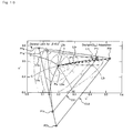
FIG. 10 shows a case when conducting video display based on a video signal conforming to the sRGB standard. The figure shows, on an u' v' chromaticity diagram, a color reproduction range CS1 displayed on the standard color gamut display and a color reproduction range CS2 displayed on the wide color gamut display.
InFIG. 10 , the positions of three points P1r, P1g, and P1b in the color reproduction range CS1 of the standard color gamut display show red, green, and blue of the highest saturation in the color reproduction range CS1, respectively. Similarly, the positions of three points P2r, P2g, and P2b in the color reproduction range CS2 of the wide color gamut display show red, green, and blue of the highest saturation in the color reproduction range CS2, respectively.
As shown inFIG. 10 , the color reproduction range CS2 is broader than the color reproduction range CS1, and the wide color gamut display is therefore displayable of colors having the saturation higher than that of the standard color gamut display. - And also, in
FIG. 10 , a straight line L1r (an equal hue line of red) is shown with a thick dash line that represents a color range of an equal hue from achromatic colors (position of a point Pw) of the lowest saturation to red (position of a point P1r) of the highest saturation in the standard color reproduction range CS1. Similarly, inFIG. 10 , a straight line L2r (an equal hue line of red) is shown with a thick dash line that represents a color range of an equal hue from achromatic colors (position of a point Pw) of the lowest saturation to red (position of a point P2r) of the highest saturation in the expanded color reproduction range CS2.
Furthermore,FIG. 10 shows solid lines: L0r, L0g, L0b, L0c, L0m, and L0y, for red, green, blue, cyan, magenta, and yellow, respectively that represent a color range of equal hues visually sensed as having the same hue from achromatic colors to each color (chromatic color). In short, the solid lines L0r, L0g, L0b, L0c, L0m, and L0y represent the equal hue lines of each color: red, green, blue, cyan, magenta, and yellow. The visually equal hue lines L0r, L0g, L0b, L0c, L0m, and L0y for each color shown inFIG. 10 are also described in theNonpatent literature 1. - Here, the red hue is described.
As shown inFIG. 10 , the visually equal hue line of red L0r has a shape curved in a direction having a convexed shape near the yellow hue.
The red equal hue line L1r in the standard color reproduction range CS 1 is a straight line, however, closely resembles to the visually equal hue line of red L0r. Therefore, when video display based on a video signal conforming to the sRGB standard is conducted on the standard color gamut display, the reddish video is reproduced by colors having approximately the same hues from achromatic colors (position of the point Pw) to a color of the highest saturation (position of the point P1r). However, the color reproduction range CS1 of the standard color gamut display is narrow, and thus, the brightness for displaying red having a high saturation lacks.
Additionally, the red equal hue line L1r in the standard color reproduction range CS1 has red of the highest saturation (the position P2r) that closely resembles to the visual red of a high saturation.
Therefore, when video display based on a video signal conforming to the sRGB standard is conducted on the wide color gamut display, with respect to red having an extremely high saturation, the primary color the video signal indicates is reproduced highly brightly in the video. -
- Patent literature 1: Japanese Unexamined Patent Publication No.
H08-130655 - Nonpatent Literature 1: G. Wyszecki, and W.S. Stiles, Color Science: Concepts and Methods, Quantitative Data and Formulae (2nd ed.), pp.447, John Wiley & Sons, New York, 2000
- However, when conducting video display on the wide color gamut display based on a video signal conforming to the sRGB standard employed in a common television broadcasting, there occurs a problem of color deviation that a color different from an original color is displayed particularly on a portion of the color region having an intermediate saturation. For example, with respect to the red hue shown in
FIG. 10 , an equal hue line of red L 1r in the standard color reproduction range CS 1 is a straight line and, in the portion of an intermediate saturation, has a great gap against the visually equal hue line of red L0r. Therefore, when video display based on a video signal conforming to the sRGB standard is conducted on the wide color gamut display, with respect to red having an intermediate saturation, the visual hue largely displaces from the red of the highest saturation, causing a color deviation of a magenta-tinged color. Particularly, when a color deviation occurs in a video of skin tone including a red color component having an intermediate saturation, an user (viewer) might feel the video very unnatural. In addition, color deviations, such as that the tone should be a skin tone is displayed in a red-tinged color, and the color should be red is displayed in a magenta-tinged color, may occur.
There is, therefore, a demand for correcting such color deviations for colors in a partial range.
And also, there has been a demand for colors in an arbitrary partial color region in the entire color reproduction range be converted into favorable colors without a sense of discomfort, even when a color gamut is not expanded.
As described in thePatent literature 1, a video signal may be subjected to color gamut compression processing, so that the video is displayed in the standard color reproduction range CS 1 on the wide color gamut display.
However, to provide a video signal with the color gamut compression processing causes an unfavorable correction of a signal value in the color region not requiring a color adjustment. For example, when video display is conducted on the wide color gamut display based on a video signal obtained by providing the video signal conforming to the sRGB standard with the color gamut compression processing, the wide color gamut display displayable of bright red having a high saturation cannot be fully utilized.
In addition, when conducting color adjustment (correction of a signal value of a video signal) for eliminating the color deviation in a portion in a color region or for correcting colors in an arbitrary portion of a color region to favorable colors, it is preferred that the color adjustment can be executed with a high degree of freedom and the parameter setting for the color adjustment is easy.
Accordingly, the present invention has been completed on the basis of the above circumstances, and its object is to provide a video display device capable of color adjustments for eliminating a color deviation in a portion of a color region in a color reproduction range and correcting a color in an arbitrary portion in a color region to a favorable color, and moreover, the video display device easily implementing a parameter setting for such a color adjustment. - To achieve the above object, a video display device according to the present invention corrects a signal value of an input video signal and displays a video based on a corrected video signal on a display, the video display device comprising each element shown in the following (1) to (3).
- (1) a designated color region setting means for setting a designated range of each of a luminance, a saturation and a hue
- (2) a reference correction coefficient setting means for setting a reference correction coefficient of a luminance, a saturation and a hue
- (3) a signal correcting means for correcting a luminance, a saturation and a hue of a color by the correction quantity corresponding to a reference correction coefficient with regard to a signal value of an input video signal indicating a color within a designated color region defined by a designated range of the luminance, the saturation, and the hue when the color indicated by the signal value is a color in the center of the designated color region or at a core for occupying a predetermined range around the center, the signal correcting means otherwise correcting each of a luminance, a saturation, and a hue of a color of the signal value by the correction quantity gradually smaller as a position in a color space of the color indicated by the signal value approaches a boundary position of the designated color region
- A video display device according to the present invention conducts a color adjustment (correction of a signal value of the input video signal) of a designated portion of a color region (the designated color region) in a color reproduction range of the input video signal. Accordingly, when a color deviation occurs in a portion of a color region in a color reproduction range, a video display device according to the present invention can conduct a video display, eliminating the color deviation with the input video signal used as it is, while utilizing the content of the input video signal as it is in other color regions. In addition, a video display device according to the present invention is preferable not only for eliminating a color deviation but for conducting a color adjustment for correcting a color in an arbitrary portion of a color region to a favorable color.
For example, when the input video signal is a video signal conforming to the sRGB standard and the display is a wide color gamut display, the wide color gamut display displayable of bright primary colors (R, G, and B) each having a high saturation can be fully utilized, eliminating a color deviation of a color (skin tone and the like) having an intermediate saturation.
Additionally, with respect to a signal value indicating a color within the designated color region, a signal value of a color at the core (center) in the designated color region is corrected by the correction quantity in accordance with the reference correction coefficient that has been set, whereas signal values of other colors are corrected by the correction quantity gradually smaller as a position of the color approaches a boundary position of the designated color region. Therefore, before/after the signal value correction, the color continuity (gradation) can be ensured.
The reference correction coefficient may be applied to a color region occupying a predetermined range at the center of the designated color region, and this case, the core may be a position occupying a predetermined range around the center of the designated color region.
In the present invention, designation (setting) of the designated color region and a correction coefficient for a color as color adjustment parameters is conducted separately for each of three independent parameters: luminance, saturation, and hue, which specify a color. Therefore, there is no need to consider the mutual interference of each parameter, allowing an easy setting of color adjustment parameters. - In addition, for example, the designated color region setting means may set a center value of each of a luminance, a saturation, and a hue in the designated color region or a designated value of a width of each of the luminance, the saturation, and the hue based on the center value in accordance with an operation input, so as to set a designated range of each of the luminance, the saturation, and the hue.
This allows an user to directly set (input) the center position of the designated color region as a reference of the color adjustment (signal value correction) and a correction coefficient (the reference correction coefficient) of a color in the center position. Accordingly, the relationship between a setting value (designated value) and a result of the color adjustment can be easily understood.
Additionally, the designated color region setting means may set a designated value of a width of each of the luminance, the saturation, and the hue by selecting from a plurality of predetermined candidate values in accordance with an operation input.
This facilitates a setting (designation) of color adjustment parameters, even though the degree of freedom of the color adjustment might be somewhat sacrificed. - The core may be a portion occupying a range of a previously set ratio with respect to the designated color region around the center position in the designated color region.
When the size of the core is required to be enlarged/reduced as the size change of the designated color region, this omits a changing process of a parameter designating the size of the core in accordance with every change of the designated color region setting, and thereby facilitating a setting (designation) of color adjustment parameters.
A video display device according to the present invention may comprise an element as shown in the following (4). - (4) a core selecting means for selecting, in accordance with an operation input, between whether the center position in the designated color region is the core or a portion occupying a range of a predetermined ratio with respect to the designated color region around the center position in the designated color region
- And also, the signal correcting means may conduct the processing shown in the following (4-1).
- (4-1) The signal correcting means calculates the correction quantity of a saturation gradually smaller as its position approaches a boundary position exclusively within the region wherein the saturation value is greater than or equal to zero and including the center position or the core, when a signal value of the input video signal to be corrected includes within the designated color region a region where a saturation value in the color space becomes negative
With a small component value of a saturation included in a signal value of an input video signal to be corrected, a designated color region set by the designated color region setting means may include a region wherein the component of a saturation in the color space is negative. However, the lower limit value of a component value of a saturation of an input video signal to be corrected is actually zero. Here, the correction quantity of a saturation gradually smaller as its position approaches a boundary position is calculated exclusively within a range of a region, wherein the lower limit value of a component value of a saturation included in a signal value of the input video signal is equal to or greater than zero, in a designated color region set by the designated color region setting means. This enables a more precise calculation of the correction quantity of a saturation gradually smaller as its position approaches a boundary position, as compared with a calculation including a region wherein the component of a saturation becomes negative.
Additionally, a video display device according to the present invention may comprise an element as shown in the following (5). - (5) a weight correction coefficient setting means for setting the correction quantity of each of a luminance, a saturation, and a hue gradually smaller as approaching a boundary position to a value same as the reference correction coefficient or a prescribed first value of each of a luminance, a saturation, and a hue
- And also, the signal correcting means may conduct the processing shown in the following (4-2).
- (4-2) With an origin position in the color space included in the designated color region as a reference position for correcting a signal value of the input video signal, the signal correcting means corrects each of a luminance, a saturation, and a hue of a color of the signal after adding a prescribed second value to a value indicating the origin position, and, after the correction, subtracts the prescribed second value from a value indicating the signal
- According to the present invention, with a color deviation occurred in a partial color region in a color reproduction range using an input video signal as it is, like in a case of conducting a video display on a wide color gamut display based on a video signal conforming to the sRGB standard, the color deviation can be eliminated by an easy setting of color adjustment parameters. While in other color regions, a video display can be conducted fully utilizing the content of an input video signal as it is. Furthermore, the present invention also enables an easy color adjustment, when a color in an arbitrary partial color region in the entire color reproduction range is required to be converted into a favorable color without a sense of discomfort.
-
-
FIG. 1 is a block diagram showing a general structure of a liquid crystal display device X as an example of a video display device according to an embodiment of the present invention; -
FIG. 2 is a view showing an example of a color adjustment screen in the video display device X; -
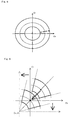
FIG. 3 viewed in a direction orthogonal to a Y-axis in a Ycbcr coordinate system shows a first example of a designated color region and a core as a color adjustment target of the liquid crystal display device X; -
FIG. 4 viewed in a Y-axis direction in a Ycbcr coordinate system shows the first example of a designated color region and a core as a color adjustment target of the liquid crystal display device X; -
FIG. 5 is a perspective view showing the first example of a designated color region and a core as a color adjustment target of the liquid crystal display device X; -
FIG. 6 viewed in a direction orthogonal to a Y-axis in a Ycbcr coordinate system shows a second example of a designated color region and a core as a color adjustment target of the liquid crystal display device X; -
FIG. 7 viewed in a Y-axis direction in a Ycbcr coordinate system shows the second example of a designated color region and a core as a color adjustment target of the liquid crystal display device X; -
FIG. 8 viewed in a Y-axis direction in a Ycbcr coordinate system shows an example wherein a hue weight Wt is adjusted to 1 in the entire designated color region as a color adjustment target of the liquid crystal display device X; -
FIG. 9 viewed in a Y-axis direction in a Ycbcr coordinate system shows an example wherein an origin on a plane CbCr as a color adjustment reference of the liquid crystal display device X is offset; -
FIG. 10 shows a color reproduction range of a standard color gamut display and a color reproduction range of a wide color gamut display on an u' v' chromaticity diagram, in a case of conducting video display based on a video signal conforming to the sRGB standard. -
- X...liquid crystal display device
- 1...video signal input unit
- 2...video processing circuit
- 3...liquid crystal driving circuit
- 4...liquid crystal panel
- 5...LED feed circuit
- 6...LED backlight
- 7...light control circuit
- 8...main control circuit
- 81...MPU
- 82...EEPROM
- Ax...designated color range
- Ay...core
- Further features and advantages of the present invention will become more readily apparent from the following detailed description when taken in conjunction with the accompanying drawings. Additionally, the following embodiment is merely an example of the present invention which should not limit the technical scope of the present invention.
- Firstly, the configuration of a liquid crystal display device X as an example of a video display device according to an embodiment of the present invention is described with reference to a block diagram shown in
FIG. 1 .
As can be seen fromFIG. 1 , the liquid crystal display device X includes a videosignal input unit 1, avideo processing circuit 2, a liquidcrystal driving circuit 3, aliquid crystal panel 4, anLED feed circuit 5, anLED backlight 6, alight control circuit 7, and amain control circuit 8, and the like.
TheLED backlight 6 having an LED as a light source illuminates theliquid crystal panel 4. The LEDs are aligned on the rear surface side of theliquid crystal panel 4 displaying a video, being a light source constituted by a white LED or LEDs of three RGB colors (three LEDs).
Theliquid crystal panel 4 illuminated by theLED backlight 6 is an example of a wide color gamut display for, when the input video signal conforming to the sRGB standard is input to the liquidcrystal driving circuit 3 through the videosignal input unit 1 and thevideo processing circuit 2, displaying video in colors in the expanded color reproduction range CS2 (seeFIG. 10 ) wider than the color reproduction range of the sRGB standard (the standard color reproduction range CS1 inFIG. 10 ). In addition, a backlight having a light source other than an LED may be employed. - The video
signal input unit 1 is an interface for inputting a video signal. Hereinafter, a video signal input through the videosignal input unit 1 is referred to as "input video signal".
Thevideo processing circuit 2 executes various signal processing based on the input video signal.
For example, thevideo processing circuit 2 corrects a signal value of the input video signal in accordance with a command from themain control circuit 8.
More particularly, upon receiving a command for operating in the later-described "standard mode" from themain control circuit 8, thevideo processing circuit 2 conducts color gamut compression to the input video signal. This color gamut compression processing is, as can be seen from, for example, thePatent literature 1, for a compression correction of a signal value of the input video signal, so that a display color of the liquid crystal panel 4 (wide color gamut display) at the time when the input video signal is a video signal conforming to the sRGB standard is within the standard colorreproduction range CS 1. This allows the video based on the input video signal conforming to the sRGB standard to be displayed on theliquid crystal panel 4 in colors nearly the same as the display colors on the conventional standard color gamut display. The particular details of the color gamut compression processing are omitted here in the description.
In addition, upon receiving a command for operating in the later-described "bright mode" from themain control circuit 8, thevideo processing circuit 2 executes a color adjustment processing for adjusting (correcting) a display color on theliquid crystal panel 4 by correcting a signal value of the input video signal. The details of the color adjustment processing are described later. - In addition, the
video processing circuit 2 sequentially generates a frame signal showing a video luminance (pixel gradation) of each primary color (R, G, and B) in each pixel that constitutes image of one frame in a moving image, based on the input video signal for one frame or the display target video signal for one frame as a signal obtained by conducting the color adjustment processing to the input video signal, and sends the frame signal to the liquidcrystal driving circuit 3.
Additionally, every time when the input video signal for one frame is input, thevideo processing circuit 2 calculates an average luminance level (so called, APL: Average Picture Level), regarding the input video signal as a reference value of the video luminance (gradation level) in the display target video signal, and sends the calculated result to thelight control circuit 7. The average luminance level is a weighted average value of a video luminance (gradation level) of each primary color (R, G, and B) in each pixel in the display target video signal for one frame. - Based on the frame signal sequentially transmitted from the
video processing circuit 2 in a prescribed cycle, the liquidcrystal driving circuit 3 sequentially displays a video for one frame (image in one frame) corresponding to the frame signal on theliquid crystal panel 4.
More particularly, the liquidcrystal driving circuit 3 supplies a gradation signal having a voltage (gradation voltage) in accordance with a gradation level (may be called a luminance level) of each primary color (R, G, and B) to a liquid crystal element in each pixel provided in the liquid crystal display panel. This allows theliquid crystal panel 4 to display a video (moving image) based on the input video signal. - The
light control circuit 7 determines a luminance of each LED in theLED backlight 6, based on the average luminance level found (calculated) by thevideo processing circuit 2. Furthermore, thelight control circuit 7 decides a control value (for example, a duty ratio in a PWM control) of a supplying voltage for each LED in theLED backlight 6 in accordance with the determined luminance, and sets (outputs) the control value to theLED feed circuit 5.
TheLED feed circuit 5 supplies electrical power in accordance with the control value set by thelight control circuit 7 to each LED in theLED backlight 6. This adjusts the luminance of theLED backlight 6 to the luminance determined by thelight control circuit 7.
Additionally, thevideo processing circuit 2 and thelight control circuit 7 are embodied by, for example, a FPGA and an ASIC, and the like. - The
LED feed circuit 5 adjusts supplying power for each LED in theLED backlight 6 according to a control command from thelight control circuit 7. For example, theLED feed circuit 5 adjusts the supplying power for each LED by the PWM control. Or, theLED feed circuit 5 may conduct the light control of each LED by adjusting the DC voltage level.
Themain control circuit 8 comprises aMPU 81 as a calculating means and anEEPROM 82 as a nonvolatile memory. With control programs stored in a ROM not shown executed by theMPU 81, themain control circuit 8 executes control processing of each element in the liquid crystal display device X.
For example, in themain control circuit 8, theMPU 81 conducts switching processing of video display modes in accordance with an operation input through a remote operator not shown. Here, the video display mode is an operating mode of thevideo processing circuit 2.
More particularly, theMPU 81 conducts the switching processing between a standard mode and a bright mode as the two video display modes in accordance with an operation input. Then, a command for operating in the switched video display mode is output from theMPU 81 to thevideo processing circuit 2.
The standard mode is an operating mode for executing the color gamut compression processing to the input video signal so that a display color of the liquid crystal panel 4 (wide color gamut display) is compressed to the standard color reproduction range CS1 from the expanded color reproduction range CS2 shown inFIG. 10 .
On the other hand, in the bright mode, the color adjustment processing for adjusting (correcting) a color indicated by the input video signal is executed by correcting a signal value of the input video signal conforming to the sRGB standard, and thereby eliminating a color deviation in a partial designated color region in the expanded color reproduction range CS2. - Next, in reference to
FIGs. 3 to 5 , a color region as a target for the color adjustment processing executed in the bright mode is described. InFIGs. 2 to 5 , the same symbols are allotted to the same information (parameters).
When a signal value of the input video signal is a signal value indicating a color within a color region (hereinafter, referred to as a designated color region Ax) to be set (designated) by an operation input of an user, thevideo processing circuit 2 conducts the color adjustment processing (correction of a signal value) to the signal value. -
FIG. 2 shows an example of a color adjustment screen displayed on theliquid crystal panel 4. This color adjustment screen is for confirming a setting of color adjustment parameters used in the color adjustment processing and a result of the color adjustment processing based on the color adjustment parameters.
Upon detecting a prescribed operation input, for example, a pressing operation of a color adjustment key through a remote operator (operating unit) not shown, theMPU 81 in themain control circuit 8 outputs a command to thevideo processing circuit 2, so that the color adjustment screen is displayed on theliquid crystal panel 4. - Then, the
MPU 81 sets the color adjustment parameters in accordance with the user's operation input on a numeric number key in the remote operator.
The color adjustment parameters include parameters: yc, rc, tc, yw, rw, and tw, relating to a designated range of each of a luminance, a saturation, and a hue specifying the designated color region Ax as a color adjustment target, and reference correction coefficients: kbri, ksat, and khye, as a reference for an adjustment quantity of each of a luminance, a saturation, and a hue. In other words, theMPU 81 is an example of a designated color region setting means for setting a designated range of each of a luminance, a saturation, and a hue, while at the same time being an example of a reference correction coefficient setting means for setting reference correction coefficient of each of a luminance, a saturation, and a hue. In addition, the parameters relating to a designated range of each of a luminance, a saturation, and a hue include in the designated color region Ax: yc as a center value of a luminance, rc as a center value of a saturation, tc as a center value of a hue, and, based on each of these center values as a reference, yw as a width of a luminance, rw as a width of a saturation, and tw as a width of a hue. Namely, the designated color region Ax is a color region identified by a designated range of each of the luminance, the saturation, and the hue specified by these parameters yc, rc, tc, yw, rw, and tw.
The color adjustment parameters theMPU 81 has set in accordance with an operation input are recorded in theEERPOM 82 in thecontrol circuit 8. -
FIGs. 3 to 5 show an example of the designated color region Ax and a core Ay as a center position Pc in the designated color region Ax on a Ycbcr coordinate system.
In the present embodiment, the width yw of the luminance, the width rw of the saturation, and the width tw of the hue are parameters indicating one second of the entire width of each of a luminance, a saturation, and a hue in the designated color region Ax. However, the width yw of the luminance, the width rw of the saturation, and the width tw of the hue may be parameters indicating the entire width of each of a luminance, a saturation, and a hue in the designated color region Ax. InFIGs. 2 to 5 , ys is the minimum value (=ycyw) and ye is the maximum value (=yc-yw) of a luminance both specifying a range of the designated color region Ax; rs is the minimum value (=rc-rw) and re is the maximum value (=rc+rw) both specifying a range of a saturation of the designated color region Ax; and ts is the minimum value (=tc-tw) and tc is the maximum value (=tc+rw) both specifying a range of a hue in the designated color region Ax.
These parameters: ys, rs, ts, ye, re, and te may be set as parameters of a designated range of each of the luminance, the saturation, and the hue, specifying the designated color region Ax. - Next, a concrete example of the color adjustment processing executed in the bright mode is described. In the input video signal, a Y value (luminance value), a Cb value (a differential signal value of blue), and a Cr value (a differential signal value of red) are Yin, Cbin, and Crin, respectively.
Firstly, thevideo processing circuit 2 calculates polar coordinates (rin, tin) for identifying a saturation and a hue on the Cb-Cr plane of the input video signal, based on the values Cb and Cr of the input video signal (Cbin, Crin). The polar coordinates (rin, tin) can be calculated based on the known Cordic (Cordinate Rotation Computer) algorithm.
Then, thevideo processing circuit 2 calculates deviations (ΔYin, Δrin, and Δtin) against a color in the core Ay in colors (Yin, rin, and tin) of the input video signal, based on the next formula (A1). Additionally, the following formulae (A1) to (A3) are based on a case where the core Ay is a center position Pc in the designated color region Ax.
- Δyin: a deviation of a luminance of an input video signal against a luminance of a core
- Δrin: a deviation of a saturation of an input video signal against a saturation of a core
- Δtin: a deviation of a hue of an input video signal against a hue of a core
- Yin: a luminance value of an input video signal
- (a polar coordinate of a luminance of an input video signal in a Ycbcr color space)
- rin: a polar coordinate of a saturation of an input video signal in a Ycbcr color space
- tin: a polar coordinate of a hue of an input video signal in a Ycbcr color space
- yc: a polar coordinate (setting value) of a luminance at the center position in a designated color region in a Ycbcr color space
- rc: a polar coordinate (setting value) of a saturation at the center position in a designated color region in a Ycbcr color space
- tc: a polar coordinate (setting value) of a hue at the center position in a designated color region in a Ycbcr color space
- *core: a conter position in a designated color region in a Ycbcr color space
- Wyrt: weight coefficient for color adjustment
- ΔYin: deviation of a luminance of an input video signal against a luminance, of a core
- Δrin: deviation of a saturation of an input video signal against a saturation of a core
- Δtin: deviation of a hue of an input video signal against a hue of a core
- rc: polar coordinate (setting value) of a saturation at the center position in a designated color region in a Ycbcr color space
- yw: designated value (setting value) of a width of a luminance of a designated color region in a Ycbcr color space
- rw: designated value (setting value) of a width of a saturation of a designated color region in a Ycbcr color space
- tw: designated value (setting value) of a width of a hue of a designated color region in a Ycbcr color space
- *core: center position in a designated color region in a Ycbcr color space
- Yin: luminance value of an input video signal
- Cbin: Cb value of an input video signal
- Crin: Cr value of an input video signal
- Yout: luminance value of a video signal after correction
- Cbout: Cb value of a video signal after correction
- Crout: Cr value of a video signal after correction
- Wyrt: weight coefficient for color adjustment
- kbri: correction coefficient (setting value) of a luminance
- ksat: correction coefficient (setting value) of a saturation
- khue: correction coefficient (setting value) of a hue
- The next formula (A0) integrates the above formulae (A1) to (A3).

- Yin: luminance value of an input video signal (polar coordinate of a luminance of an input video signal in a Ycbcr color space)
- Cbin: Cb value of an input video signal
- Crin: Cr value of an input video signal
- Yout: luminance value of a video signal after correction
- Cbout: Cb value of a video signal after correction
- Crout: Cr value of a video signal after correction
- rin: porlar coordinate of a saturation of an input video signal in a Ycbcr color space
- tin: porlar coordinate of a hue of an input video signal in a Ycbcr color space
- yc: porlar coordinate (setting value) of a luminance at the center position in a designated color region in a Ycbcr color space
- rc: porlar coordinate (setting value) of a saturation at the center position in a designated color region in a Ycbcr color space
- tc: porlar coordinate (setting value) of a hue at the center position in a designated color region in a Ycbcr color space
- yw: designated value (setting value) of a width of a luminance of a designated color region in a Ycbcr color space
- rw: designated value (setting value) of a width of a saturation of a designated color region in a Ycbcr color space
- tw: designated value (setting value) of a width of a hue of a designated color region in a Ycbcr color space
- kbri: correction coefficient (setting value) of a luminance
- ksat,: correction coefficient (setting value) of a saturation
- khue: correction coefficient (setting value) of a hue
- With the color adjustment processing based on the above formulae (A1) to (A3), the video processing circuit 2 (an example of a signal correcting means) corrects a signal value of the input video signal indicating a color within the designated color region Ax as below.
In other words, when a color indicated by a signal value of the input video signal is a color in the core Ay (here, the center position Pc) in the designated color region Ax, the weight coefficient for the color correction is Wyrt=1, and each of a luminance Yin, a saturation rin, and a hue tin of the color is corrected only by the correction quantity corresponding to the reference correction coefficient (kbri, ksat, and khue). Here, the correction quantity (adding amount) of each of a luminance, a saturation, and a hue is a value obtained by multiplying the luminance yin, the saturation rin, and the hue tin of the input video signal by the reference correction coefficients kbri, ksat, and kue, respectively.
In addition, when a color indicated by a signal value of the input video signal is a color other than a color in the core Ay in the designated color region Ax (in otherwise), the weight coefficient Wyrt for the color correction reaches closer to 0 as the position in a color space of a color indicated by a signal value of the input video signal approaches a boundary position in the designated color region Ax (moves away from the core Ay). As a result, each of a luminance Yin, a saturation rin, and a hue tin of a color of a signal value is corrected only by the correction quantity gradually smaller as a position of a color of the signal value of the input video signal approaches a boundary position of the designated color region Ax. Additionally, a correction quantity of a signal value of a color at a boundary position of the designated color region Ax is zero. Therefore, before/after the signal value correction, the color continuity (gradation) can be ensured. - The example in
FIG. 2 shows a color adjustment screen including distribution charts g1 and g2 of display colors in the designated color region Ax at the time of conducting the color adjustment processing based on the set color adjustment parameters. With such distribution charts g1 and g2 displayed on theliquid crystal panel 4, an user can understand at a glance how setting values of the color adjustment parameters are reflected on an actual color correction. - As a variation of the color adjustment processing, the next formula (A4) may be employed in calculating a weight coefficient Wyrt for a color correction, instead of the above formula (A2).

In the formula (A4), - Wyrt: weight coefficient for color adjustment
- Wy: weight coefficient for color adjustment of a luminance
- Wr: weight coefficients for color adjustment of a saturation
- Wt: weight coefficient for color adjustment of a hue
- Δyin: deviation of a luminance of an input video signal against a luminance of a core
- Δrin: deviation of a saturation of an input video signal against a saturation of a core
- Δtin: deviation of a hue of an input video signal against a hue of a core
- rc: polar coordinate (setting value) of a saturation at the center position in a designated color region in a Ycbcr color space
- yw: designated value (setting value) of a width of a luminance of a designated color region in a Ycbcr color space
- rw: designated value (setting value) of a width of a saturation of a designated color region in a Ycbcr color space
- tw: designated value (setting value) of a width of a hue of a designated color region in a Ycbcr color space
- *core: center position in a designated color region in a Ycbcr color space
- As a variation of the color adjustment processing, the next formula (A5) may be employed in calculating values Cb' and Cr', instead of the above formula (A3).

- Cboff: offset to a Cb value of an input video signal
- Croff: offset to a Cr value of an input video signal
- There may be a case where a color region occupying a certain range at the center of the designated color region Ax is the core Ay, and the reference correction coefficients (kbri, ksat, and khue) is required to be applied to the core Ay. In this case, the core Ay only needs to be a position occupying a predetermined range around a center position Pc in the designated color region Ax.
FIGs. 6 and 7 show an example (the second example) of the designated color region Ax and the core Ay, with the core Ay occupying a certain range around the center position Pc.
Here, for example, a parameter (hereinafter, referred to as "core ratio setting value") specifying a occupying ratio of the core Ay with respect to the designated color region Ax may be previously set and previously recorded in theEEPROM 2 in themain control circuit 8. In this case, the core Ay is a portion occupying a range of a prescribed ratio (ratio determined by the core ratio setting value) with respect to the designated color region Ax around a center position Pc in the designated color region Ax.
Additionally, the core ratio setting value may be set in accordance with an operation input of an user via a screen shown inFIG. 2 and a remote operator and the like, and, other than that, be previously set to a fixed value.
The core ratio setting value indicates, for example, a ratio of a width of a luminance, a saturation, and a hue of the core Ay, with respect to a luminance width (=2×yw), a saturation width (=2×rw), and a hue width (=2×tw) in the designated color region Ax.FIGs 6 and 7 are examples wherein the ratio is generally 20%. - Then, the
MPU 81 in themain control circuit 8 may specify a range of the core Ay based on parameters of the designated color region Ax and the core ratio setting value and send information of the specified result to thevideo processing circuit 2.
When the size of the core Ay is required to be enlarged/reduced as the size change of the designated color region Ax, this omits a changing process of a parameter designating the size of the core Ay in accordance with every setting change of the designated color region Ax, and thereby facilitating a setting (designation) of color adjustment parameters. - Next, a concrete example of the color adjustment processing executed in the bright mode, with a predetermined range occupied by the core Ay is described.
Firstly, thevideo processing circuit 2, as mentioned above, calculates polar coordinates (rin, tin) for identifying the saturation and the hue on a Cb-Cr plane of the input video signal, based on the values Cb and Cr (Cbin, Crin) of the input video signal.
Then, thevideo processing circuit 2 calculates deviations (ΔYin, Δrin, and Δtin) against colors in the core Ay in colors (Yin, rin, and tin) of the input video signal, based on the next formula (B1).
- Δyin: deviation of a luminance of an input video signal against a luminance of a core
- Δrin: deviation of a saturation of an input video signal against a saturation of a core
- Δtin: deviation of a hue of an input video signal against a hue of a core
- Yin: luminance value of an input video signal (polar coordinate of a luminance of an input video signal in a Ycbcr color space)
- rin: porlar coordinate of a saturation of an input video signal in a Ycbcr color space
- tin: porlar coordinate of a hue of an input video signal in a Ycbcr color space
- yc: porlar coordinate (setting value) of a luminance at the center position in a designated color region in a Ycbcr color space
- rc: porlar coordinate (setting value) of a saturation at the center position in a designated color region in a Ycbcr color space
- tc: porlar coordinate (setting value) of a hue at the center position in a designated color region in a Ycbcr color space
- kcore: ratio (setting value) of a core with respect to a designated color region
- *core: a prescribed range having a center position in a designated color region in a Ycbcr color space as a center
- Wyrt: weight coefficient for color adjustment
- Δyin: deviation of a luminance of an input video signal against a luminance of a core
- Δrin: deviation of a saturation of an input video signal against a saturation of a core
- Δtin: deviation of a hue of an input video signal against a hue of a core
- rc: porlar coordinate (setting value) of a saturation at the center position in a designated color region in a Ycbcr color space
- yw: designated value (setting value) of a width of a luminance of a designated color region in a Ycbcr color space
- rw: designated value (setting value) of a width of a saturation of a designated color region in a Ycbcr color space
- tw: designated value (setting value) of a width of a hue of a designated color region in a Ycbcr color space
- kcore: ratio (setting value) of a core with respect to a designated color region
- *core: a prescribed range having a center position in a designated color region in a Ycbcr color space as a center
- Yin: luminance value of an input video signal
- Cbin: Cb value of an input video signal
- Crin: Cr value of an input video signal
- Yout: luminance value of a video signal after correction
- Cbout: Cb value of a video signal after correction
- Crout: Cr value of a video signal after correction
- Wyrt: weight coefficient for color adjustment
- kbri: correction coefficient (setting value) of a luminance
- ksat: correction coefficient (setting value) of a saturation
- khue: correction coefficient (setting value) of a hue
- The next formula (B0) integrates the above formulae (B1) to (B3).

- Yin: luminance value of an input video signal (polar coordinate of a luminance of an input video signal in a Ycbcr color space)
- Cbin: Cb value of an input video signal
- Crin: Cr value of an input video signal
- Yout: luminance value of a video signal after correction
- Cbout: Cb value of a video signal after correction
- Crout: Cr value of a video signal after correction
- rin: porlar coordinate of a saturation of an input video signal in a Ycbcr color space
- tin: porlar coordinate of a hue of an input video signal in a Ycbcr color space
- yc: porlar coordinate (setting value) of a luminance at the center position in a designated color region in a Ycbcr color space
- rc: porlar coordinate (setting value) of a saturation at the center position in a designated color region in a Ycbcr color space
- tc: porlar coordinate (setting value) of a hue at the center position in a designated color region In a Ycbcr color space
- yw: designated value (setting value) of a width of luminance of a designated color region in a Ycbcr color space
- rw: designated value (setting value) of a width of a saturation of a designated color region in a Ycbcr color space
- tw: designated value (setting value) of a width of a hue of a designated color region in a Ycbcr color space
- kcore: ratio (setting value) of a core with respect to a designated color region
- kbri: correction coefficient (setting value) of a luminance
- ksat: correction coefficient (setting value) of a saturation
- khue: correction coefficient (setting value) of a hue
- *core: a prescribed range having a center position in a designated color region in a Ycbcr color space as a center
- As a variation of the color adjustment processing, the next formula (B4) may be employed in calculating a weight coefficient Wyrt for a color correction, instead of the above formula (A2).

- Wyrt: weight coefficient for color adjustment
- Wy: weight coefficient for color adjustment of a luminance
- Wr: weight coefficient for color adjustment of a saturation
- Wt: weight coefficient for color adjustment of a hue
- Δyin: deviation of a luminance of an input video signal against a luminance of a core
- Δrin: deviation of a saturation of an input video signal against a saturation of a core
- Δtin: deviation of a hue of an input video signal against a hue of a core
- rc: polar coordinate (setting value) of a saturation at the center position in a designated color region in a Ycbcr color space
- yw: designated value (setting value) of a width of a luminance of a designated color region in a Ycbcr color space
- rw: designated value (setting value) of a width of a saturation of a designated color region in a Ycbcr color space
- tw: designated value (setting value) of a width of a hue of a designated color region in a Ycbcr color space
- *core: center position in a designated color region in a Ycbcr color space
- As a variation of the color adjustment processing, the next formula (B5) may be employed in calculating values Cb' and Cr', instead of the above formula (B3).

- Cboff. offset to a Cb value of an input video signal
- Croff: offset to a Cr value of an input video signal
- In the above embodiment, the
MPU 81 sets designated values yw, rw, and tw of a width of each of a luminance, a saturation, and a hue in accordance with an operation input on a numeral key in a remote operator not shown, however, other setting methods may be employed.
For example, a plurality of candidates (hereinafter, referred to as "designated width candidate data") of combinations of designated values yw, rw, and tw of a width of each of a luminance, a saturation, and a hue may be previously recorded in theEEPROM 82. In this case, theMPU 81 sets designated values yw, rw, and tw of a width of each of the luminance, the saturation, and the hue by selecting from a plurality of designated width candidate data in accordance with an operation input on a selection key in the remote operator. A plurality of designated width candidate data is, for example, previously set by being divided into three levels (large, medium, and small) or five levels (large, slightly large, medium, slightly small, and small).
This facilitates a setting (designation) of color adjustment parameters, even though the degree of freedom of the color adjustment might be somewhat sacrificed.
Additionally, in a video display device capable of switching the video display mode among a plurality of modes (such as, a standard mode, a bright mode), an setting value of color adjustment parameters appropriate for each video display mode may be previously known. In such a case, the color adjustment parameters for each video display mode may be previously recorded in a memory such as theEEPROM 82, so that theMPU 81 automatically selects the color adjustment parameters supporting the video display mode and sets the parameters in thevideo processing circuit 2. - And also, the MPU 81 (an example of a core selecting means) in the
main control circuit 8 may select (switch), in accordance with an operation input by an user through the remote operator and the like, between whether the core Ay is the center position Pc in the designated color region Ax or a portion occupying a range of a ratio previously set with respect to the designated color region Ax around the center position Pc in the designated color region Ax.
This allows the degree of freedom of the color adjustment to be enhanced, without increasing time and labor for setting color adjustment parameters. - The present invention is applicable to a video display device.
Also, an example for a typical wide color gamut display is a liquid crystal panel illuminated by a backlight having an LED as a light source.
With a signal value to be corrected in the origin position, a prescribed value is added to the signal value, and the component information of a saturation and a hue is added to the signal value, so that a signal value of the input video signal can be corrected. The information padded for the correction is deleted by subtracting a prescribed value from a corrected signal value of the input video signal.
This allows the signal correcting means to correct a signal value of the input video signal even when the signal value indicates an achromatic color. And also, this processing corrects a color temperature of white indicated by an input video signal, without changing the gamma of a television set.
Moreover, at the origin position, a value indicating a saturation and a hue and included in a signal value of the input video signal may be zero.
This facilitates an easy identification of an origin position in the color space as a reference for calculating the correction value when correcting a signal value of an input video signal.

Then, the

When a prescribed first value set to a weight coefficient for a color correction for every component of each of a luminance, a saturation, and a hue is less than 1 (for example, 0.5), the component of each of a luminance, a saturation, and a hue of the input video signal is corrected by a value smaller than the reference correction coefficient. When the first prescribed value is greater than 1 (for example, 1.5), the component of each of a luminance, a saturation, and a hue of the input video signal is corrected by a value greater than the reference correction coefficient.
As shown in
Here, as shown in
An origin position in the color space where a value of the input video signal to be corrected is a reference for calculating a correction value is preferred to be subjected to the processing, along with a position where the component of a saturation and a hue included in a value of the input signal becomes zero.
A prescribed value to be offset can be identified arbitrarily in accordance with a processing system per example of a prescribed second value, and may be 1, 2, -1, and -2.

Then, the

Claims (11)
- A video display device for correcting a signal value of an input video signal and displaying a video based on a corrected video signal on a display, the video display device comprising:a designated color region setting means for setting a designated range of a luminance, a saturation, and a hue;a reference correction coefficient setting means for setting a reference correction coefficient of a luminance, a saturation, and a hue; anda signal correcting means for correcting a luminance, a saturation and a hue of a color by the correction quantity corresponding to a reference correction coefficient with regard to a signal value of an input video signal indicating a color within a designated color region defined by a designated range of the luminance, the saturation, and the hue when the color indicated by the signal value is a color in the center position in the designated color region or at a core occupying a predetermined range around the center, the signal correcting means otherwise correcting each of a luminance, a saturation, and a hue of a color of the signal value by the correction quantity gradually smaller as a position in a color space of the color indicated by the signal value approaches a boundary position of the designated color region.
- The video display device according to Claim 1 for setting a center value of each of a luminance, a saturation, and a hue in the designated color region and a designated value of a width of each of the luminance, the saturation, and the hue based on the center value in accordance with an operation input, so as to set a designated range of each of the luminance, the saturation, and the hue.
- The video display device according to Claim 2 wherein the designated color region setting means sets a designated value of a width of each of the luminance, the saturation, and the hue by selecting from a plurality of predetermined candidate values in accordance with an operation input.
- The video display device according to any one of Claims 1 to 3, wherein the core is a portion occupying a range of a previously set ratio with respect to the designated color region around the center position in the designated color region.
- The video display device according to any one of Claims 1 to 4, comprising a core selecting means for selecting, in accordance with an operation input, between whether the center position in the designated color region is the core or a portion occupying a range of a predetermined ratio with respect to the designated color region around the center position in the designated color region.
- The video display device according to any one of Claims 1 to 5, wherein the signal correcting means calculates the correction quantity of a saturation gradually smaller as its position approaches a boundary position exclusively within a region wherein a saturation value is greater than or equal to zero and including the center position or the core, when a signal value of the input video signal to be corrected includes within the designated color region a region wherein a saturation value in the color space becomes negative.
- The video display device according to any one of Claims 1 to 6, further comprising a weight correction coefficient setting means for setting a correction quantity of each of a luminance, a saturation, and a hue gradually smaller as approaching a boundary position to a value same as the reference correction coefficient or a prescribed first value of each of the luminance, the saturation, and the hue.
- The video display device according to any one of Claims 1 to 7, wherein, with an origin position in the color space included in the designated color region as a reference position for correcting a signal value of the input video signal, the signal correcting means corrects each of a luminance, a saturation, and a hue of a color of the signal after adding a prescribed second value to a value indicating the origin position, and, after the correction, subtracts the prescribed second value from a value indicating the signal.
- The video display device according to Claim 8, wherein, at the origin position, a value indicating a saturation and a hue and included in a signal value of the input video signal is zero.
- The video display device according to any one of Claims 1 to 9, wherein the input video signal is a video signal conforming to the sRGB standard, and the display is a wide color gamut display developing a color reproduction range wider than the color reproduction range of the sRGB standard, upon receiving a video signal conforming to the sRGB standard.
- The video display device according to Claim 10, wherein the wide color gamut display is a liquid crystal panel illuminated by a backlight having an LED as a light source.
Applications Claiming Priority (3)
| Application Number | Priority Date | Filing Date | Title |
|---|---|---|---|
| JP2008221884 | 2008-08-29 | ||
| JP2009192555A JP4523667B2 (en) | 2008-08-29 | 2009-08-21 | Video display device |
| PCT/JP2009/064921 WO2010024313A1 (en) | 2008-08-29 | 2009-08-27 | Image display apparatus |
Publications (2)
| Publication Number | Publication Date |
|---|---|
| EP2323411A1 true EP2323411A1 (en) | 2011-05-18 |
| EP2323411A4 EP2323411A4 (en) | 2013-10-02 |
Family
ID=41721479
Family Applications (1)
| Application Number | Title | Priority Date | Filing Date |
|---|---|---|---|
| EP09809963.3A Withdrawn EP2323411A4 (en) | 2008-08-29 | 2009-08-27 | IMAGE DISPLAY APPARATUS |
Country Status (7)
| Country | Link |
|---|---|
| US (1) | US20110187735A1 (en) |
| EP (1) | EP2323411A4 (en) |
| JP (1) | JP4523667B2 (en) |
| CN (1) | CN102132572B (en) |
| MX (1) | MX2011002044A (en) |
| RU (1) | RU2011107741A (en) |
| WO (1) | WO2010024313A1 (en) |
Families Citing this family (16)
| Publication number | Priority date | Publication date | Assignee | Title |
|---|---|---|---|---|
| US8824006B2 (en) * | 2010-08-23 | 2014-09-02 | Kabushiki Kaisha Toshiba | Color correction apparatus and color correction method |
| JP5950652B2 (en) * | 2011-04-08 | 2016-07-13 | ローム株式会社 | Image processing circuit, semiconductor device, and image processing device |
| US20130100484A1 (en) * | 2011-10-24 | 2013-04-25 | John L. Hankins | Public Network Printing System |
| KR20140093364A (en) * | 2013-01-16 | 2014-07-28 | 삼성전자주식회사 | Apparatus and method for generating medical image |
| US9807358B2 (en) * | 2014-02-06 | 2017-10-31 | Stmicroelectronics S.R.L. | Method and system for chromatic gamut extension, corresponding apparatus and computer program product |
| JP2015152645A (en) * | 2014-02-10 | 2015-08-24 | シナプティクス・ディスプレイ・デバイス合同会社 | Image processing apparatus, image processing method, display panel driver, and display apparatus |
| JP6287337B2 (en) * | 2014-02-28 | 2018-03-07 | 富士ゼロックス株式会社 | Image processing apparatus, image processing method, image processing system, and program |
| JP6400331B2 (en) * | 2014-05-22 | 2018-10-03 | ラピスセミコンダクタ株式会社 | Display panel driving apparatus and display panel driving method |
| TWI537873B (en) | 2015-03-18 | 2016-06-11 | 友達光電股份有限公司 | Image correction method and image correction device |
| CN107221306B (en) * | 2017-06-29 | 2019-07-16 | 上海顺久电子科技有限公司 | The method, apparatus and display equipment of brightness of image in correction splicing device screen |
| CN109308861B (en) * | 2017-07-26 | 2022-03-18 | 北京小米移动软件有限公司 | Color calibration method, device, equipment and storage medium |
| CN107818768B (en) * | 2017-10-10 | 2019-09-17 | 惠科股份有限公司 | Driving method and driving device of display device |
| CN110880306B (en) * | 2019-11-01 | 2021-03-30 | 南京图格医疗科技有限公司 | Color restoration correction method for medical display |
| KR102832586B1 (en) | 2020-11-05 | 2025-07-11 | 주식회사 엘엑스세미콘 | Color gamut mapping method and device |
| KR20240164686A (en) * | 2023-05-12 | 2024-11-20 | 삼성디스플레이 주식회사 | Dipslay device and method of driving the same |
| US20260004701A1 (en) * | 2024-06-27 | 2026-01-01 | Dell Products L.P. | Mode transition on a dual-resolution display |
Family Cites Families (25)
| Publication number | Priority date | Publication date | Assignee | Title |
|---|---|---|---|---|
| JPH0678320A (en) * | 1992-08-25 | 1994-03-18 | Matsushita Electric Ind Co Ltd | Color adjustment device |
| JP3344016B2 (en) * | 1993-08-23 | 2002-11-11 | 三菱電機株式会社 | Video signal processing device |
| US6434266B1 (en) * | 1993-12-17 | 2002-08-13 | Canon Kabushiki Kaisha | Image processing method and apparatus for converting colors in a color image |
| JPH08130655A (en) * | 1994-10-31 | 1996-05-21 | Canon Inc | Image processing method and apparatus |
| JP2830871B2 (en) * | 1996-11-18 | 1998-12-02 | 日本電気株式会社 | Image color correction device and recording medium storing color correction program |
| WO1998042142A1 (en) * | 1997-03-14 | 1998-09-24 | Sony Corporation | Color correction device, color correction method, picture processing device, and picture processing method |
| JPH11155099A (en) * | 1997-11-21 | 1999-06-08 | Sharp Corp | Electronic zoom processing device |
| JP4058244B2 (en) * | 2000-01-26 | 2008-03-05 | 富士フイルム株式会社 | Image processing method |
| US7113310B2 (en) * | 2000-01-26 | 2006-09-26 | Fuji Photo Film Co., Ltd. | Method of processing image |
| US6477271B1 (en) * | 2000-04-07 | 2002-11-05 | Avid Technology, Inc. | Secondary color modification of a digital image |
| JP3561680B2 (en) * | 2000-07-14 | 2004-09-02 | 三洋電機株式会社 | Digital camera |
| JP4489262B2 (en) * | 2000-07-28 | 2010-06-23 | 日立プラズマディスプレイ株式会社 | Color reproduction correction circuit for color display and color display |
| JP3760815B2 (en) * | 2001-07-27 | 2006-03-29 | 株式会社日立製作所 | Video display device |
| US7215813B2 (en) * | 2001-12-03 | 2007-05-08 | Apple Computer, Inc. | Method and apparatus for color correction |
| JP3620529B2 (en) * | 2002-03-18 | 2005-02-16 | 日本ビクター株式会社 | Video correction apparatus and method, video correction program, and recording medium recording the same |
| US6844881B1 (en) * | 2002-03-29 | 2005-01-18 | Apple Computer, Inc. | Method and apparatus for improved color correction |
| EP1538848A4 (en) * | 2002-09-12 | 2009-04-15 | Panasonic Corp | IMAGE PROCESSING DEVICE |
| JP4126487B2 (en) * | 2002-11-08 | 2008-07-30 | 株式会社沖データ | Image conversion method and image conversion apparatus |
| JP4046647B2 (en) * | 2003-05-29 | 2008-02-13 | 松下電器産業株式会社 | Color adjustment apparatus and method |
| US7668365B2 (en) * | 2004-03-08 | 2010-02-23 | Seiko Epson Corporation | Determination of main object on image and improvement of image quality according to main object |
| JP3901173B2 (en) * | 2004-06-07 | 2007-04-04 | セイコーエプソン株式会社 | Image processing apparatus, image processing method, and image processing program |
| US20060251323A1 (en) * | 2005-05-05 | 2006-11-09 | Genesis Microchip Inc. | Detection, correction fading and processing in hue, saturation and luminance directions |
| JP4652992B2 (en) * | 2006-02-23 | 2011-03-16 | ルネサスエレクトロニクス株式会社 | Color correction apparatus, color correction method, and program |
| CN101543084A (en) * | 2006-11-30 | 2009-09-23 | Nxp股份有限公司 | Device and method for processing color image data |
| US20080266314A1 (en) * | 2007-04-26 | 2008-10-30 | Mark Melvin Butterworth | Nonlinearly extending a color gamut of an image |
-
2009
- 2009-08-21 JP JP2009192555A patent/JP4523667B2/en not_active Expired - Fee Related
- 2009-08-27 MX MX2011002044A patent/MX2011002044A/en active IP Right Grant
- 2009-08-27 US US13/060,411 patent/US20110187735A1/en not_active Abandoned
- 2009-08-27 RU RU2011107741/07A patent/RU2011107741A/en not_active Application Discontinuation
- 2009-08-27 WO PCT/JP2009/064921 patent/WO2010024313A1/en not_active Ceased
- 2009-08-27 CN CN200980134106.8A patent/CN102132572B/en not_active Expired - Fee Related
- 2009-08-27 EP EP09809963.3A patent/EP2323411A4/en not_active Withdrawn
Also Published As
| Publication number | Publication date |
|---|---|
| MX2011002044A (en) | 2011-04-21 |
| JP2010079285A (en) | 2010-04-08 |
| WO2010024313A1 (en) | 2010-03-04 |
| CN102132572A (en) | 2011-07-20 |
| JP4523667B2 (en) | 2010-08-11 |
| EP2323411A4 (en) | 2013-10-02 |
| RU2011107741A (en) | 2012-10-10 |
| CN102132572B (en) | 2014-05-14 |
| US20110187735A1 (en) | 2011-08-04 |
Similar Documents
| Publication | Publication Date | Title |
|---|---|---|
| EP2323411A1 (en) | Image display apparatus | |
| CN101218619B (en) | Method and apparatus for converting signal for driving display and display using same | |
| US7251361B2 (en) | Automatic saturation adjustment | |
| US8786585B2 (en) | System and method for adjusting display based on detected environment | |
| US8619132B2 (en) | Wide color gamut anaglyphs | |
| US20090060326A1 (en) | Image processing apparatus and method | |
| EP2487892A1 (en) | Method and apparatus for brightness-controlling image conversion | |
| KR100736939B1 (en) | Intelligent color gamut management method | |
| WO2003003716A1 (en) | Image processing device, image processing method, program, and recording medium | |
| TWI278825B (en) | Color display device, color compensation method, color compensation program, and storage medium readable by computer | |
| US20140092122A1 (en) | Image display apparatus and method therefor | |
| JP4422190B1 (en) | Video display device | |
| JP4542600B2 (en) | Video display device | |
| JP4951054B2 (en) | Video display device | |
| CN102164289B (en) | Method and/or apparatus for implementing a color management module | |
| HK1157552A (en) | Image display apparatus | |
| JP2008099170A (en) | Image processing apparatus and image processing method | |
| HK1163987A (en) | Video display device |
Legal Events
| Date | Code | Title | Description |
|---|---|---|---|
| PUAI | Public reference made under article 153(3) epc to a published international application that has entered the european phase |
Free format text: ORIGINAL CODE: 0009012 |
|
| 17P | Request for examination filed |
Effective date: 20110222 |
|
| AK | Designated contracting states |
Kind code of ref document: A1 Designated state(s): AT BE BG CH CY CZ DE DK EE ES FI FR GB GR HR HU IE IS IT LI LT LU LV MC MK MT NL NO PL PT RO SE SI SK SM TR |
|
| AX | Request for extension of the european patent |
Extension state: AL BA RS |
|
| DAX | Request for extension of the european patent (deleted) | ||
| A4 | Supplementary search report drawn up and despatched |
Effective date: 20130903 |
|
| RIC1 | Information provided on ipc code assigned before grant |
Ipc: G09G 5/02 20060101ALI20130828BHEP Ipc: G09G 3/20 20060101ALI20130828BHEP Ipc: G09G 5/10 20060101ALI20130828BHEP Ipc: G09G 3/34 20060101ALI20130828BHEP Ipc: H04N 9/64 20060101AFI20130828BHEP Ipc: G09G 5/36 20060101ALI20130828BHEP Ipc: G09G 3/36 20060101ALI20130828BHEP Ipc: G06T 1/00 20060101ALI20130828BHEP |
|
| STAA | Information on the status of an ep patent application or granted ep patent |
Free format text: STATUS: THE APPLICATION HAS BEEN WITHDRAWN |
|
| 18W | Application withdrawn |
Effective date: 20131021 |