EP2323239A1 - Integrierte Station für Gleichstromzufuhr zu geografisch entfernten Verbrauchern, beispielsweise einer Telekommunikationsantenne - Google Patents
Integrierte Station für Gleichstromzufuhr zu geografisch entfernten Verbrauchern, beispielsweise einer Telekommunikationsantenne Download PDFInfo
- Publication number
- EP2323239A1 EP2323239A1 EP09425455A EP09425455A EP2323239A1 EP 2323239 A1 EP2323239 A1 EP 2323239A1 EP 09425455 A EP09425455 A EP 09425455A EP 09425455 A EP09425455 A EP 09425455A EP 2323239 A1 EP2323239 A1 EP 2323239A1
- Authority
- EP
- European Patent Office
- Prior art keywords
- batteries
- integrated station
- framework
- generating set
- generator
- Prior art date
- Legal status (The legal status is an assumption and is not a legal conclusion. Google has not performed a legal analysis and makes no representation as to the accuracy of the status listed.)
- Ceased
Links
Images


Classifications
-
- H—ELECTRICITY
- H02—GENERATION; CONVERSION OR DISTRIBUTION OF ELECTRIC POWER
- H02J—CIRCUIT ARRANGEMENTS OR SYSTEMS FOR SUPPLYING OR DISTRIBUTING ELECTRIC POWER; SYSTEMS FOR STORING ELECTRIC ENERGY
- H02J7/00—Circuit arrangements for charging or depolarising batteries or for supplying loads from batteries
- H02J7/14—Circuit arrangements for charging or depolarising batteries or for supplying loads from batteries for charging batteries from dynamo-electric generators driven at varying speed, e.g. on vehicle
- H02J7/1415—Circuit arrangements for charging or depolarising batteries or for supplying loads from batteries for charging batteries from dynamo-electric generators driven at varying speed, e.g. on vehicle with a generator driven by a prime mover other than the motor of a vehicle
-
- H—ELECTRICITY
- H02—GENERATION; CONVERSION OR DISTRIBUTION OF ELECTRIC POWER
- H02J—CIRCUIT ARRANGEMENTS OR SYSTEMS FOR SUPPLYING OR DISTRIBUTING ELECTRIC POWER; SYSTEMS FOR STORING ELECTRIC ENERGY
- H02J7/00—Circuit arrangements for charging or depolarising batteries or for supplying loads from batteries
- H02J7/14—Circuit arrangements for charging or depolarising batteries or for supplying loads from batteries for charging batteries from dynamo-electric generators driven at varying speed, e.g. on vehicle
- H02J7/1469—Regulation of the charging current or voltage otherwise than by variation of field
- H02J7/1476—Regulation of the charging current or voltage otherwise than by variation of field by mechanical action on the generator
-
- H—ELECTRICITY
- H02—GENERATION; CONVERSION OR DISTRIBUTION OF ELECTRIC POWER
- H02P—CONTROL OR REGULATION OF ELECTRIC MOTORS, ELECTRIC GENERATORS OR DYNAMO-ELECTRIC CONVERTERS; CONTROLLING TRANSFORMERS, REACTORS OR CHOKE COILS
- H02P9/00—Arrangements for controlling electric generators for the purpose of obtaining a desired output
- H02P9/04—Control effected upon non-electric prime mover and dependent upon electric output value of the generator
-
- H—ELECTRICITY
- H02—GENERATION; CONVERSION OR DISTRIBUTION OF ELECTRIC POWER
- H02P—CONTROL OR REGULATION OF ELECTRIC MOTORS, ELECTRIC GENERATORS OR DYNAMO-ELECTRIC CONVERTERS; CONTROLLING TRANSFORMERS, REACTORS OR CHOKE COILS
- H02P9/00—Arrangements for controlling electric generators for the purpose of obtaining a desired output
- H02P9/48—Arrangements for obtaining a constant output value at varying speed of the generator, e.g. on vehicle
Definitions
- the present invention relates in its more general aspect to an integrated station for DC electric supply to geographically isolated loads, for example telecommunications antennas.
- the invention relates in particular, but not exclusively, to an integrated station for DC electric supply to geographically isolated loads, such as for example telecommunications antennas, of the type comprising:
- the invention likewise relates to a method for direct DC electric supply to a geographically isolated load, such as for example a telecommunications antenna, and by means of at least one generating set appliance comprising:
- This primary need is associated with a further need which is that of reducing as far as possible the maintenance work on the generating set, without reducing but instead extending the working life of the generating set itself.
- the prior art seeks to offer a solution to these combined needs, for example by optimising the functioning of the internal combustion engine which actuates the generator of the generating set and/or by oversizing the fuel tank associated with this engine.
- the technical problem at the basis of the present invention is that of devising an integrated station for DC electric supply to geographically isolated loads, such as for example telecommunications antennas, which station has structural and functional features such as to allow a drastic reduction in the running costs with the same service provided or energy or electrical power supplied and a considerable lengthening of the working life of the generating set incorporated in the same station.
- Another object of the present invention is that of making available to the user a sort of UPS unit which allows, in the event of a fault or temporary stoppage of the generating set, the possibility of delaying maintenance work, guaranteeing in any case supply to the load or the possibility of performing operations of maintenance and reset, maintaining the supply to the load for a predetermined length of time.
- a further object of the present invention is that of making the generating set of the integrated supply station work always at an optimal rate, reducing the consumption of fuel and the needs for periodical maintenance.
- an object of the present invention is that of making available an integrated station wherein the direct current supplied to the load is rectified in the simplest and most direct way possible, avoiding a complex phase of regulation or conversion of the alternating current produced by the generator.
- the proposed idea which lies at the basis of the present invention is that of making available apparatus of the "hybrid" type, i.e. capable of supplying the load via direct current delivered by a set of batteries incorporated in the supply station and of using the generating set to charge this set of batteries periodically, operating the internal combustion engine which actuates the generator of the generating set at an optimal rate of efficiency and regulating or alternating charging and discharging of the set of batteries always in an optimal manner.
- the periodical recharging takes place preferably at regular time intervals and the batteries are dimensioned in such a way as to withstand multiple cycles of charging and discharging.
- the invention also relates to a method of the type described previously and characterised in that it provides an integrated station incorporating said apparatus, and:
- 1 denotes overall and schematically an integrated and monolithic station for DC electric supply to geographically remote or isolated electrical loads 20, such as for example telecommunications antennas or any type of electrical load situated far from a connection to an electrical distribution grid.
- the electrical load 20 is external to the station 1 and is schematised only in Figure 5 .
- the integrated station 1 comprises apparatus provided with a generating set 2 which includes a DC generator 4 and which is actuated by an internal combustion engine 6.
- the generator 4 comprises only an alternator and a relative rectifier, in that the regulation of the direct current to the level required by the users at 24V or at 48V is performed upstream of the rectifier on the excitation of the alternator so as to have AC voltage which is always suitable for guaranteeing the correct value of DC voltage in output in every instantaneous load condition.
- the alternator of the generator 4 is actuated by the internal combustion engine 6, for example a diesel cycle engine powered conventionally with naphtha or diesel.
- the integrated station 1 comprises advantageously at least one set of batteries 15 and an electronic command and control unit 10 which regulates and supervises the functioning of the engine 6 and the phases of charging and discharging of the set of batteries.
- the electronic unit 10 performs other functions of control of the entire station 1.
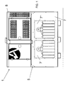
- the integrated station 1 comprises a framework 5 for support, enclosure and protection.
- the generating set 2 the set of batteries 15 and the electronic command and control unit 10 which has a plurality of signal inputs receiving electrical pulses from various sensors of sets 2 and 15 and has a plurality of command outputs connected to various actuator devices of the sets 2 and 15, as will be made clearer by the rest of the description and by Figure 4 .
- the framework 5 has a substantially parallelepiped shape and comprises a lower portion 7 and an upper portion 8.
- the lower portion 7 houses centrally a fuel tank 3 for the engine 6.
- the presence of the tank could be optional in the sense that there is nothing against providing this tank in the vicinity of the station 1 and in such a way as to be structurally independent and connectable to the engine of the generating set 2 by means of a conduit for feeding fluid fuel.
- a central housing is provided for the tank 3.
- the spaces 7', 7" for housing of the sets 15' and 15" of batteries on opposite sides of the framework 5 allow facilitation of the maintenance operations and a check on the state of the batteries or removal of one or more of them. Moreover, in this way, a better balancing of the total weight of the integrated station 1 is achieved, given that the set of batteries 15, composed of the subsets 15' and 15", contributes to about half of the total weight of the integrated station 1.
- the upper portion 8 of the framework 5 houses the generating set 2 with the generator 4 actuated by the internal combustion engine 6.
- the diesel engine 6 is a variable speed engine with continuity. More particularly the work pace of the engine is regulated, in every load condition, to that of optimal efficiency of the same engine for that load condition.
- the engine 6 is subject to varying of the working revs or turns on command and control of the electronic unit 10 in order to function substantially in the region of a maximum torque speed or maximum efficiency according to the needs of supply of the load.
- the electronic unit 10 detects by means of sensors the number of rotation revs of the engine 6 and the absorption of current or the voltage of the set of batteries 15, regulating the supply of fuel to the engine in order to vary the number of revs thereof according to the recharging needs.
- the engine 6 of the present invention allows regulation of its number of revs so as to work as far as possible in the region of the maximum torque speed at which there is maximum generation of electrical power for a given engine.
- the engine 6 can be made to function at optimal rate supplying the maximum electrical power.
- the engine 6 can be made to function at a lower rotation rate, obtaining a saving in the consumption of fuel.
- the generator 4 of the generating set 5 actuated by the engine 6 generates in output direct current electrical power which supplies directly the set of batteries 15 via an automatic protection circuit breaker 12 which protects the generating set 2 from a possible short circuit of one or both sets of batteries 15', 15".
- the batteries of the set 15 can be electrically connected in series or in parallel according to the needs of supply of the load at 24 V or at 48 V DC.
- the connections between the batteries are illustrated by lines 19 of Figure 4 .
- the batteries of sets 15' and 15" are substantially interposed as a buffer between the generating set 2 and the load 20 and via a second automatic protection circuit breaker 25 which performs its action in the case of a possible short circuit on the load 20.
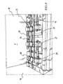
- the batteries of the set 15 are preferably rechargeable lead acid batteries, without thereby entailing any limitation on the rights of the Applicant, and are each provided with a top-up cap 27 also provided with a float valve and a relief valve 29 for the gases produced by the battery.
- Figure 4 shows a detail wherefrom it is possible to note the presence of the white float 23 when the liquid in the container 22 of a battery is at its maximum level.
- each battery is housed in a respective container 22 which is oversized in relation to a container normally used for that type of batteries and with the same generated DC electrical power or voltage.
- This technique allows the containing of a quantity of acid higher than usual and with covering of the cells of the battery, for example a larger volume of acid by about 20%, in such a way as to guarantee a predetermined reserve in consideration of the fact that the integrated station 1 is installed near geographically remote and isolated electrical loads and the aim is to reduce to a minimum the maintenance work.
- the batteries of the sets 15' and 15" are regularly arranged in rows one next to the other with the top-up caps 27 turned upwards.
- each cap 27 has a first through hole 28 in fluid communication with a conduit 24 for feeding acid mixture liquid.
- the conduit 24 has a feed section which runs above all the caps 27 and all the holes 28 of the caps 27 of the batteries are connected to this feed section of the conduit 24 which also has a join section which descends from a tank 35 of acid situated in the upper portion 8 of the framework 5.
- the other holes 29 of the caps 27 are in fluid communication one with the other and by means of an emission conduit 21 which runs parallel to the feed section of the conduit 24 and which flows out into a ventilated space 33 of the upper portion 8 of the framework 5.
- the sets 15' and 15" of batteries are housed in spaces 7' and 7" insulated by walls 16 of insulant material and maintained at a temperature constantly below 30° or 40° C (according to the climates) to increase their working life.
- the electronic unit 10 actuates an air-conditioning system 18 inside the framework 5 whenever the internal temperature exceeds for example 27°C or 33°C.
- the air-conditioning system 18 is supplied electrically by the same set of batteries 15.
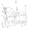
- the unit 10 comprises a microprocessor motherboard 14 having a plurality of inputs of signals connected to sensors of the alternator 4, of the engine 6 and also to temperature sensors of the space for housing of the same.
- the board 14 is connected in output to protection circuit breakers SH, to the generating set 2 and to the transmitter 30.
- the board 14 is coupled to the batteries 15 and to the load 20.
- the unit 10 is therefore able to perform different operations of supervision of the integrated station 1 and to report possible states of fault or malfunctioning, such as for example:
- the electronic command and control unit 10 periodically actuates the generating set 2 to charge the set of batteries 15.
- This periodical recharging can take place at pre-established intervals of time, for example every six hours, alternated or spaced by periods of time wherein the set of batteries 15 supplies DC power directly to the load 20 of the users without being recharged by the generating set 2.
- the period of discharge has been chosen so that the residual charge of the batteries is at least 50%, in such a way as to both encourage the phase of recharging and avoid excessive discharges of the set of batteries 15 which reduce the working life thereof.
- the maintaining of a residual charge of at least 50% of the storage capacity of the set of batteries 15 also allows conferring to the integrated station 1 of the capacity of sustaining supply to the load per a predetermined length of time also in the case of a fault which requires the intervention of maintenance staff. The latter may reach the integrated station 1 with awareness that the service supplied has not however been interrupted.
- the electronic unit 10 does not only regulate in timed mode the cycle of charging and discharging of the set of batteries, but is also able to interrupt charging on detection of a charge level that is more than adequate for the purposes of supply of the load. Therefore recharging or its interruption takes place both on a timed basis and on a consensus signal detected by means of sensors of the charge level or of absorption of current by the set of batteries 15.
- intervention on the generating set 2 could also allow a prolonging of the intervals of maintenance, exploiting in combination the systems whereof the integrated station 1 is equipped.
- intervention on the generating set 2 could also allow a prolonging of the intervals of maintenance, exploiting in combination the systems whereof the integrated station 1 is equipped.
- This system allows an improvement in the functioning of the engine 6 and lengthening of the maintenance periods.
- This lengthening of the maintenance periods of the engine contributes to lengthening further and overall the intervention by specialist personnel on the site of installation of the integrated station of the present invention.
- the apparatus and the method according to the present invention effectively solve the technical problem and achieve numerous advantages.
- the apparatus according to the invention reduces drastically, from 30% to even 50%, the consumption of fuel for the same energy supplied to the load and the cost for the maintenance of the generator by about 50%, being approximately 50% the number of hours of work of the prime mover in relation to the use of a normal generating set.
- the apparatus according to the invention achieves extensive range without the need for operative maintenance; operative ranges of more than 1000 hours of operation of the prime mover can even be achieved, also according to the size of the fuel tank which, considering that the hours of operation are 50%, therefore allows 2000 hours of interval between one maintenance intervention and the next.
- the engine of the 3 operates practically always in maximum torque speed and for predetermined and regularly staggered intervals of time. This allows the working life of the engine to be doubled.
- the command and control unit operates total supervision of the functions of the apparatus 1 and allows timely indication of possible faults or malfunctioning by means of the remote control functions.
Priority Applications (2)
| Application Number | Priority Date | Filing Date | Title |
|---|---|---|---|
| EP09425455A EP2323239A1 (de) | 2009-11-13 | 2009-11-13 | Integrierte Station für Gleichstromzufuhr zu geografisch entfernten Verbrauchern, beispielsweise einer Telekommunikationsantenne |
| CN2010105361652A CN102064590A (zh) | 2009-11-13 | 2010-11-09 | 用于为地理上孤立的电力负载提供dc电源的集成站 |
Applications Claiming Priority (1)
| Application Number | Priority Date | Filing Date | Title |
|---|---|---|---|
| EP09425455A EP2323239A1 (de) | 2009-11-13 | 2009-11-13 | Integrierte Station für Gleichstromzufuhr zu geografisch entfernten Verbrauchern, beispielsweise einer Telekommunikationsantenne |
Publications (1)
| Publication Number | Publication Date |
|---|---|
| EP2323239A1 true EP2323239A1 (de) | 2011-05-18 |
Family
ID=41818890
Family Applications (1)
| Application Number | Title | Priority Date | Filing Date |
|---|---|---|---|
| EP09425455A Ceased EP2323239A1 (de) | 2009-11-13 | 2009-11-13 | Integrierte Station für Gleichstromzufuhr zu geografisch entfernten Verbrauchern, beispielsweise einer Telekommunikationsantenne |
Country Status (2)
| Country | Link |
|---|---|
| EP (1) | EP2323239A1 (de) |
| CN (1) | CN102064590A (de) |
Cited By (2)
| Publication number | Priority date | Publication date | Assignee | Title |
|---|---|---|---|---|
| EP2629397A1 (de) | 2012-02-14 | 2013-08-21 | Ascot S.R.L. | Verfahren zum Wiederaufladen von Batterien einer DC Generatoreneinheit, um isolierte elektrische Lasten zu versorgen, und korrespondierendes Gerät, um das Verfahren zu implementieren |
| GB2527805A (en) * | 2014-07-02 | 2016-01-06 | Bamford Excavators Ltd | A generator set |
Families Citing this family (1)
| Publication number | Priority date | Publication date | Assignee | Title |
|---|---|---|---|---|
| US9978863B2 (en) * | 2013-08-16 | 2018-05-22 | Taiwan Semiconductor Manufacturing Company Limited | Semiconductor arrangement with one or more semiconductor columns |
Citations (3)
| Publication number | Priority date | Publication date | Assignee | Title |
|---|---|---|---|---|
| GB2417378A (en) * | 2004-08-17 | 2006-02-22 | Graeme Eric Hawksley | Battery charger and power supply control means |
| US20090228149A1 (en) * | 2006-08-17 | 2009-09-10 | Glacier Bay, Inc. | Environmental control and power system |
| EP2112761A2 (de) * | 2008-04-21 | 2009-10-28 | Glacier Bay, Inc. | Stromerzeugungssystem |
Family Cites Families (2)
| Publication number | Priority date | Publication date | Assignee | Title |
|---|---|---|---|---|
| JP2005224013A (ja) * | 2004-02-05 | 2005-08-18 | Honda Motor Co Ltd | 電源装置 |
| CN100583548C (zh) * | 2008-06-03 | 2010-01-20 | 北京化工大学 | 酸式湿法电解回收废铅酸蓄电池铅的方法 |
-
2009
- 2009-11-13 EP EP09425455A patent/EP2323239A1/de not_active Ceased
-
2010
- 2010-11-09 CN CN2010105361652A patent/CN102064590A/zh active Pending
Patent Citations (3)
| Publication number | Priority date | Publication date | Assignee | Title |
|---|---|---|---|---|
| GB2417378A (en) * | 2004-08-17 | 2006-02-22 | Graeme Eric Hawksley | Battery charger and power supply control means |
| US20090228149A1 (en) * | 2006-08-17 | 2009-09-10 | Glacier Bay, Inc. | Environmental control and power system |
| EP2112761A2 (de) * | 2008-04-21 | 2009-10-28 | Glacier Bay, Inc. | Stromerzeugungssystem |
Non-Patent Citations (7)
| Title |
|---|
| DAVID LINDEN: "Handbook of Batteries and Fuel Cells", 1 January 1984, MCGRAW-HILL BOOK COMPANY, ISBN: 0070378746, XP002577436 * |
| POLAR POWER INC.: "Automatic System Controls", 19 June 2000 (2000-06-19), pages 1 - 3, XP002577434, Retrieved from the Internet <URL:http://www.polarpowerinc.com/products/etc/automatic_system_controls.htm> [retrieved on 20100409] * |
| POLAR POWER INC.: "DC Generator 5 kW to 6.5 kW Propane/Air Cooled", 30 March 2005 (2005-03-30), pages 1 - 3, XP002577435, Retrieved from the Internet <URL:http://www.polarpowerinc.com/products/generators/5-7kwpropane_enclosure.htm> [retrieved on 20100414] * |
| POLAR POWER INC.: "Polar DC Voltage Regulator Model 710", 26 October 1999 (1999-10-26), pages 1 - 4, Retrieved from the Internet <URL:http://www.polarpowerinc.com/products/pdf/710dc-voltage-reg.PDF> [retrieved on 20150609] * |
| POLAR POWER INC.: "Telecommunication Generators", 30 March 2005 (2005-03-30), pages 1 - 2, XP002577432, Retrieved from the Internet <URL:http://www.polarpowerinc.com/telecom/generator.htm> [retrieved on 20100409] * |
| POLAR POWER INC.: "Telecommunication", 30 June 2006 (2006-06-30), pages 1, XP002577433, Retrieved from the Internet <URL:http://www.polarpowerinc.com/telecom/index.htm> [retrieved on 20100409] * |
| POLAR POWER INC.: "Why Use DC Generators", 13 December 1999 (1999-12-13), pages 1 - 3, XP002577431, Retrieved from the Internet <URL:http://www.polarpowerinc.com/products/generators/whydcaltor.htm> [retrieved on 20100409] * |
Cited By (2)
| Publication number | Priority date | Publication date | Assignee | Title |
|---|---|---|---|---|
| EP2629397A1 (de) | 2012-02-14 | 2013-08-21 | Ascot S.R.L. | Verfahren zum Wiederaufladen von Batterien einer DC Generatoreneinheit, um isolierte elektrische Lasten zu versorgen, und korrespondierendes Gerät, um das Verfahren zu implementieren |
| GB2527805A (en) * | 2014-07-02 | 2016-01-06 | Bamford Excavators Ltd | A generator set |
Also Published As
| Publication number | Publication date |
|---|---|
| CN102064590A (zh) | 2011-05-18 |
Similar Documents
| Publication | Publication Date | Title |
|---|---|---|
| CN113043893B (zh) | 用于换电站或储能站的充电系统 | |
| ES2542327T3 (es) | Red aislada y procedimiento para el funcionamiento de una red aislada | |
| CA2421785C (en) | Island network and method for operation of an island network | |
| US5917251A (en) | Method and circuit arrangement to cover peak energy demands in electrical alternating or three-phase current networks | |
| US20120056436A1 (en) | System and method to increase the overall system efficiency of internal combustion based electric generators | |
| EP2660951B1 (de) | Kommunikationsstromquelle mit multienergetischer versorgung und steuerungsverfahren dafür | |
| KR101310312B1 (ko) | 선박 전력 공급 시스템을 개조하는 방법 | |
| WO2005008808A2 (en) | Battery charging system and method | |
| EA023215B1 (ru) | Электрическое зарядное устройство | |
| CN110970937A (zh) | 一种微电网系统的能量智能化管理方法 | |
| CN110932323A (zh) | 一种微电网系统 | |
| EP2323239A1 (de) | Integrierte Station für Gleichstromzufuhr zu geografisch entfernten Verbrauchern, beispielsweise einer Telekommunikationsantenne | |
| CN113725879B (zh) | 用于存量基站的削峰填谷储能供电系统及方法 | |
| KR20180090673A (ko) | 하이브리드 에너지 저장 시스템 | |
| CN217692693U (zh) | 一种多个受控dc/dc储能模块组串架构的储能系统 | |
| CN114161983B (zh) | 一种电动车换电系统及电池包的充电方法 | |
| CN211790791U (zh) | 一种自动化微电网系统 | |
| WO2020161766A1 (ja) | 直流給電システム | |
| CN111181192A (zh) | 一种微电网系统ccs智能控制中心 | |
| CN102347617A (zh) | 清洁能源补偿的储能电站和具有清洁能源补偿的储能系统 | |
| JP4654262B2 (ja) | 直流電源システムおよびその充電方法 | |
| CN211629877U (zh) | 一种微电网系统ccs智能控制中心 | |
| US20240022088A1 (en) | Power Conservation Apparatus | |
| CN218449527U (zh) | 一种供电系统 | |
| US11764573B2 (en) | DC power supply system |
Legal Events
| Date | Code | Title | Description |
|---|---|---|---|
| PUAI | Public reference made under article 153(3) epc to a published international application that has entered the european phase |
Free format text: ORIGINAL CODE: 0009012 |
|
| AK | Designated contracting states |
Kind code of ref document: A1 Designated state(s): AT BE BG CH CY CZ DE DK EE ES FI FR GB GR HR HU IE IS IT LI LT LU LV MC MK MT NL NO PL PT RO SE SI SK SM TR |
|
| AX | Request for extension of the european patent |
Extension state: AL BA RS |
|
| 17P | Request for examination filed |
Effective date: 20110526 |
|
| 17Q | First examination report despatched |
Effective date: 20130416 |
|
| STAA | Information on the status of an ep patent application or granted ep patent |
Free format text: STATUS: THE APPLICATION HAS BEEN REFUSED |
|
| 18R | Application refused |
Effective date: 20160208 |
|
| 110E | Request filed for conversion into a national patent application [according to art. 135 epc] |
Effective date: 20160309 |