EP2323210B1 - Fuel cell system - Google Patents
Fuel cell system Download PDFInfo
- Publication number
- EP2323210B1 EP2323210B1 EP11150854A EP11150854A EP2323210B1 EP 2323210 B1 EP2323210 B1 EP 2323210B1 EP 11150854 A EP11150854 A EP 11150854A EP 11150854 A EP11150854 A EP 11150854A EP 2323210 B1 EP2323210 B1 EP 2323210B1
- Authority
- EP
- European Patent Office
- Prior art keywords
- fuel
- fuel cell
- module
- cell system
- supply device
- Prior art date
- Legal status (The legal status is an assumption and is not a legal conclusion. Google has not performed a legal analysis and makes no representation as to the accuracy of the status listed.)
- Active
Links
- 239000000446 fuel Substances 0.000 title claims abstract description 282
- 239000007800 oxidant agent Substances 0.000 claims abstract description 56
- 238000004891 communication Methods 0.000 claims abstract description 15
- 230000001590 oxidative effect Effects 0.000 claims abstract description 15
- 238000001816 cooling Methods 0.000 claims description 22
- 229910052987 metal hydride Inorganic materials 0.000 claims description 14
- 150000004681 metal hydrides Chemical class 0.000 claims description 14
- 239000000126 substance Substances 0.000 claims description 10
- 239000002918 waste heat Substances 0.000 claims description 8
- 238000001125 extrusion Methods 0.000 claims 1
- 239000003570 air Substances 0.000 description 31
- 230000008878 coupling Effects 0.000 description 12
- 238000010168 coupling process Methods 0.000 description 12
- 238000005859 coupling reaction Methods 0.000 description 12
- UFHFLCQGNIYNRP-UHFFFAOYSA-N Hydrogen Chemical compound [H][H] UFHFLCQGNIYNRP-UHFFFAOYSA-N 0.000 description 11
- 239000001257 hydrogen Substances 0.000 description 10
- 229910052739 hydrogen Inorganic materials 0.000 description 10
- 239000000463 material Substances 0.000 description 7
- QVGXLLKOCUKJST-UHFFFAOYSA-N atomic oxygen Chemical compound [O] QVGXLLKOCUKJST-UHFFFAOYSA-N 0.000 description 6
- 238000000034 method Methods 0.000 description 6
- 239000001301 oxygen Substances 0.000 description 6
- 229910052760 oxygen Inorganic materials 0.000 description 6
- 239000007789 gas Substances 0.000 description 5
- XLYOFNOQVPJJNP-UHFFFAOYSA-N water Substances O XLYOFNOQVPJJNP-UHFFFAOYSA-N 0.000 description 5
- 229920005372 Plexiglas® Polymers 0.000 description 3
- 239000004926 polymethyl methacrylate Substances 0.000 description 3
- 238000009423 ventilation Methods 0.000 description 3
- 230000006978 adaptation Effects 0.000 description 2
- 238000005868 electrolysis reaction Methods 0.000 description 2
- 239000003792 electrolyte Substances 0.000 description 2
- 239000004744 fabric Substances 0.000 description 2
- 230000002349 favourable effect Effects 0.000 description 2
- 239000012528 membrane Substances 0.000 description 2
- 239000004033 plastic Substances 0.000 description 2
- 229920003023 plastic Polymers 0.000 description 2
- 239000011343 solid material Substances 0.000 description 2
- 239000000243 solution Substances 0.000 description 2
- 239000012080 ambient air Substances 0.000 description 1
- 230000000903 blocking effect Effects 0.000 description 1
- 239000003054 catalyst Substances 0.000 description 1
- 238000002485 combustion reaction Methods 0.000 description 1
- 230000000694 effects Effects 0.000 description 1
- 239000010411 electrocatalyst Substances 0.000 description 1
- 239000012530 fluid Substances 0.000 description 1
- 238000010438 heat treatment Methods 0.000 description 1
- 150000002431 hydrogen Chemical class 0.000 description 1
- 238000002347 injection Methods 0.000 description 1
- 239000007924 injection Substances 0.000 description 1
- 238000004519 manufacturing process Methods 0.000 description 1
- 229920005597 polymer membrane Polymers 0.000 description 1
- 238000010248 power generation Methods 0.000 description 1
- 239000000376 reactant Substances 0.000 description 1
- 239000007787 solid Substances 0.000 description 1
- 239000012780 transparent material Substances 0.000 description 1
- 239000002699 waste material Substances 0.000 description 1
Images


Classifications
-
- H—ELECTRICITY
- H01—ELECTRIC ELEMENTS
- H01M—PROCESSES OR MEANS, e.g. BATTERIES, FOR THE DIRECT CONVERSION OF CHEMICAL ENERGY INTO ELECTRICAL ENERGY
- H01M8/00—Fuel cells; Manufacture thereof
- H01M8/04—Auxiliary arrangements, e.g. for control of pressure or for circulation of fluids
- H01M8/04082—Arrangements for control of reactant parameters, e.g. pressure or concentration
- H01M8/04201—Reactant storage and supply, e.g. means for feeding, pipes
-
- H—ELECTRICITY
- H01—ELECTRIC ELEMENTS
- H01M—PROCESSES OR MEANS, e.g. BATTERIES, FOR THE DIRECT CONVERSION OF CHEMICAL ENERGY INTO ELECTRICAL ENERGY
- H01M8/00—Fuel cells; Manufacture thereof
- H01M8/04—Auxiliary arrangements, e.g. for control of pressure or for circulation of fluids
- H01M8/04082—Arrangements for control of reactant parameters, e.g. pressure or concentration
- H01M8/04089—Arrangements for control of reactant parameters, e.g. pressure or concentration of gaseous reactants
- H01M8/04104—Regulation of differential pressures
-
- H—ELECTRICITY
- H01—ELECTRIC ELEMENTS
- H01M—PROCESSES OR MEANS, e.g. BATTERIES, FOR THE DIRECT CONVERSION OF CHEMICAL ENERGY INTO ELECTRICAL ENERGY
- H01M8/00—Fuel cells; Manufacture thereof
- H01M8/06—Combination of fuel cells with means for production of reactants or for treatment of residues
- H01M8/0606—Combination of fuel cells with means for production of reactants or for treatment of residues with means for production of gaseous reactants
- H01M8/065—Combination of fuel cells with means for production of reactants or for treatment of residues with means for production of gaseous reactants by dissolution of metals or alloys; by dehydriding metallic substances
-
- H—ELECTRICITY
- H01—ELECTRIC ELEMENTS
- H01M—PROCESSES OR MEANS, e.g. BATTERIES, FOR THE DIRECT CONVERSION OF CHEMICAL ENERGY INTO ELECTRICAL ENERGY
- H01M8/00—Fuel cells; Manufacture thereof
- H01M8/24—Grouping of fuel cells, e.g. stacking of fuel cells
- H01M8/2465—Details of groupings of fuel cells
- H01M8/247—Arrangements for tightening a stack, for accommodation of a stack in a tank or for assembling different tanks
- H01M8/2475—Enclosures, casings or containers of fuel cell stacks
-
- H—ELECTRICITY
- H01—ELECTRIC ELEMENTS
- H01M—PROCESSES OR MEANS, e.g. BATTERIES, FOR THE DIRECT CONVERSION OF CHEMICAL ENERGY INTO ELECTRICAL ENERGY
- H01M8/00—Fuel cells; Manufacture thereof
- H01M8/24—Grouping of fuel cells, e.g. stacking of fuel cells
- H01M8/2465—Details of groupings of fuel cells
- H01M8/2484—Details of groupings of fuel cells characterised by external manifolds
-
- H—ELECTRICITY
- H01—ELECTRIC ELEMENTS
- H01M—PROCESSES OR MEANS, e.g. BATTERIES, FOR THE DIRECT CONVERSION OF CHEMICAL ENERGY INTO ELECTRICAL ENERGY
- H01M8/00—Fuel cells; Manufacture thereof
- H01M8/24—Grouping of fuel cells, e.g. stacking of fuel cells
- H01M8/249—Grouping of fuel cells, e.g. stacking of fuel cells comprising two or more groupings of fuel cells, e.g. modular assemblies
-
- H—ELECTRICITY
- H01—ELECTRIC ELEMENTS
- H01M—PROCESSES OR MEANS, e.g. BATTERIES, FOR THE DIRECT CONVERSION OF CHEMICAL ENERGY INTO ELECTRICAL ENERGY
- H01M8/00—Fuel cells; Manufacture thereof
- H01M8/10—Fuel cells with solid electrolytes
- H01M2008/1095—Fuel cells with polymeric electrolytes
-
- Y—GENERAL TAGGING OF NEW TECHNOLOGICAL DEVELOPMENTS; GENERAL TAGGING OF CROSS-SECTIONAL TECHNOLOGIES SPANNING OVER SEVERAL SECTIONS OF THE IPC; TECHNICAL SUBJECTS COVERED BY FORMER USPC CROSS-REFERENCE ART COLLECTIONS [XRACs] AND DIGESTS
- Y02—TECHNOLOGIES OR APPLICATIONS FOR MITIGATION OR ADAPTATION AGAINST CLIMATE CHANGE
- Y02E—REDUCTION OF GREENHOUSE GAS [GHG] EMISSIONS, RELATED TO ENERGY GENERATION, TRANSMISSION OR DISTRIBUTION
- Y02E60/00—Enabling technologies; Technologies with a potential or indirect contribution to GHG emissions mitigation
- Y02E60/30—Hydrogen technology
- Y02E60/50—Fuel cells
Definitions
- the invention relates to a fuel cell system, comprising a fuel cell device with one or more fuel cell blocks, in which chemical energy can be converted into electrical energy, an oxidizer supply device for the fuel cell device, a fuel supply device for the fuel cell device, and a control device.
- Fuel cell systems comprising a fuel cell device with one or more fuel cell blocks in which chemical energy is convertible into electrical energy, an oxidizer supply device for the fuel cell device, a fuel supply device for the fuel cell device, and a control device are known, for example from US Pat DE 101 27 600 A1 or C2 or the DE 101 27 599 A1 known.
- a modular power supply system which comprises an electrolysis module with a first connection set and a power module with a second connection set.
- the first connection set set is designed for communication with a water supply and / or a hydrogen storage device and / or the power module.
- the electrolysis module and / or the power module are removable separately from the modular power system.
- a portable power generation system which has a fuel cell for generating electrical energy.
- WO 02/01663 A1 From the WO 02/01663 A1 is a fuel cell system with a fuel cell box introduced into a fuel cell unit known.
- the fuel cell system additionally has a gas generating system box, wherein in the gas generating system box components are summarized, the operating temperature above 80 ° C are.
- the gas generating system box is thermally insulated, and the fuel cell box, the gas generating system box, and optionally other boxes containing components that contain or transport hydrogen gas have box ventilation means.
- the invention has for its object to provide a flexible usable fuel cell system.
- the fuel cell device, the oxidizer supply device, the fuel supply device and a cooling device which is assigned to the fuel cell device, each designed as a module, wherein in a module, the functional components of the respective Device are arranged in a housing, the corresponding module forms a unit which is positionable as a whole, the corresponding module has a communication interface with terminals, and the cooling device module has at least one waste-heat air connection.
- modules can be produced, adjusted and positioned separately. Due to the modular structure of the fuel cell system, this can be flexibly integrated into an application. In particular, an adaptation to geometric conditions is possible.
- each module a defined interface for communication with the outside world or other modules regarding mass transfer (via material flows) and / or energy exchange and / or signal exchange is provided.
- the operating parameters with regard to material flows, electrical currents and signal currents can be adjusted separately and also optimized for each module.
- safety-relevant components can be formed separately.
- For the fuel guide is then only the fuel supply device module and the fuel cell device module relevant. The other modules are then no longer relevant to safety.
- the fuel cell system according to the invention can be in the DE 101 27 599 A1 , of the DE 101 27 600 A1 and DE 101 27 600 C2 perform the procedure described. Furthermore, the fuel cell system according to the invention can be formed as described in these publications. Reference is expressly made to these documents.
- a corresponding module has a housing in which the functional components are arranged.
- the module can be formed as a unit.
- a defined interface and in particular a defined communication interface can be arranged on the housing.
- the functional components are protected in the housing.
- the housing is at least partially made of a transparent material so that gauges such as pressure gauges can be read.
- connection or connections are arranged on the housing, via which modules can communicate with one another or with corresponding devices.
- the housing is closed. This protects the functional components located in the housing.
- the housing is gastight, in particular in the case of the fuel cell device module and the fuel supply device module. This prevents fuel from escaping at undefined locations.
- the system can be provided with a safety ventilation directly to the environment.
- connections include in particular material connections, signal connections and electrical power connections. Substances can be exchanged via the substance connections. For example, fuel is coupled out via a coupling connection of the fuel supply device module and can be coupled into this fuel via a fuel injection connection of the fuel cell device. Control signals can be injected via signal connections or control signals can be decoupled. Electrical power can be coupled in via electrical power connections or (in the case of the fuel cell device) decoupled.
- the fuel cell assembly module has oxidizer and fuel attachments and a port for coupling electrical power.
- the fuel cell device module has at least one signal connection for coupling control signals.
- control signals can be coupled in via such a connection in order to open and close a shut-off valve via which unused fuel can be discharged.
- the fuel supply module has at least one fuel port for coupling fuel. About this fuel connection, a connection to the fuel cell device can be produced.
- the fuel supply device module has at least one signal connection.
- the oxidizer supply module has at least one oxidizer port for coupling oxidizer. It can thereby decouple air with atmospheric oxygen as an oxidizer. This connection can be used to connect to a fuel cell device.
- the oxidizer supply device module has at least one signal connection via which, in particular, control signals can be coupled in.
- modules are connected via lines.
- the modules can first be separated and positioned independently of each other on an application.
- the necessary communication connections with regard to material transport, supply of electrical power and with respect to control signals are then produced subsequently according to the geometric conditions. This results in a flexible structure, wherein the fuel cell system according to the invention is formed by subsystems.
- the lines of the module (s) are separate elements.
- one or more fuel reservoirs are integrated into the fuel supply module. For example, if a fuel storage is deflated, then the fuel supply module is replaced as a whole.
- At least one fuel storage is provided, which is coupled to the fuel supply device and in particular forms an external element with respect to a fuel supply device module.
- a fuel storage module may be coupled to a fuel supply module. If a fuel storage is drained, then a corresponding fuel storage module can be easily replaced.
- the at least one fuel storage or the at least one fuel storage module is designed as a structural element of the fuel cell system or an application.
- the energy supply device of the application which is formed with the aid of the fuel cell system, can save space.
- the at least one fuel storage or the at least one fuel storage module is or comprises a metal hydride storage.
- a metal hydride storage hydrogen is not stored as free gas, but in bound form. For example, by heating, hydrogen can be driven out of such a metal hydride storage. It does not occur the security problems as in the hydrogen storage in a pressure tank.
- a metal hydride reservoir is a solid element that can be used as a structural element and, for example, as a structural element for an application.
- the at least one fuel storage is formed by means of one or more extruded profiles.
- Corresponding metal hydride reservoirs are available, for example, under the name MH Hydrogene Storage Tank from SUMITOMO PRECISION PRODUCTS CO., LTD., Japan.
- the fuel cell device is associated with a cooling device. As a result, they can be operated with optimized efficiency.
- the cooling device is arranged and designed such that at least one fuel reservoir can be acted upon by waste-heat air.
- the waste heat air can then be used to expel hydrogen, for example from a metal hydride storage.
- the efficiency of the fuel cell system can be improved.
- the cooling device is integrated with the fuel cell device in a fuel cell module.
- the cooling device is designed as a module.
- the refrigerator module has at least one waste air outlet.
- waste heat can be decoupled, for example, to supply them to a metal hydride storage.
- the cooling device module has at least one signal connection.
- the corresponding cooling device can then be controlled via control signals in such a way that an optimum cooling effect results.
- control device is designed as a module.
- the control device then forms a separate component of the fuel cell system.
- a central control device is realized.
- control device by means of the control device a sequence control is formed, which transmits preset control signals. There is no control of the fuel supply and Oxidatorzu Adjustment to the fuel cell device, but at most one control.
- a corresponding method is in the DE 101 27 600 A1 described with reference to this document.
- control device It is advantageous if electrical consumers of the fuel cell system are supplied with electrical energy via the control device.
- the control device then provides a defined interface, via which the corresponding modules can obtain the electrical energy in the required form.
- a module has, for example, a block-shaped plastic housing. In such a block-shaped plastic housing can be formed via a hole a cloth guide.
- the pressure outputable fuel is set for the fuel supply device.
- the fuel cell device 12 is the fuel cell core device of the fuel cell system 10. Further, the fuel cell system 10 comprises a fuel supply device 16, by means of which the fuel cell or blocks 14 of the Fuel cell device 12 can be supplied with fuel.
- the fuel cell system 10 includes an oxidizer supply device 18 for the fuel cell device 12, by means of which the fuel cell or blocks 14 oxidizer can be provided.
- a control device 20 is provided for controlling the fuel cell system 10.
- the one or more fuel cell blocks 14 may be associated with a cooling device 22.
- the fuel cells of the fuel cell block or blocks 14 are, in particular, polymer membrane fuel cells (PEFC), in which the electrolyte is formed by a proton-conducting membrane.
- PEFC polymer membrane fuel cells
- the membrane is also catalyst support for the anodic and cathodic electrocatalysts and serves as a separator for the gaseous reactants.
- hydrogen is used and as an oxidizer oxygen and in particular atmospheric oxygen.
- the fuel cell device 12 is then fed air with oxygen in the air as the oxidizer.
- the fuel cell system 10 is modularly constructed with a fuel cell device module 26, a fuel supply module 28, and an oxidizer supply module 30.
- controller module 32 which comprises the controller 20.
- the cooling device 22 is integrated in a cooling device module 34.
- a fuel storage module 36 is provided.
- fuel storage it is also possible for fuel storage to be integrated with the fuel supply module 28.
- the oxidizer supply module 30 has a closed housing 38.
- the housing may be designed gas-tight.
- the housing is transparent.
- One possible material is Plexiglas.
- the oxidizer supply module 30 is provided with a communication interface 40 having an output port 42 through which the oxidizer can be coupled.
- air can be coupled out as oxidizer carrier with atmospheric oxygen as oxidizer.
- an electrical connection 44 is provided, via which electrical energy can be coupled into the oxidizer supply device module 30 for provision to electrical consumers of this module.
- a signal connection 46 may be provided for the coupling of control signals.
- the respective terminals 42, 44 and 46 are disposed on the housing 38.
- an air compressor 48 is arranged in the housing 38. This is preceded by a filter 50.
- the housing 38 has one or more air supply openings 52, via which air can be supplied to the air compressor 48, wherein the filter 50 must be passed through the supplied air.
- an air conveyor and cooler 54 is arranged, which in particular is driven by an electric motor.
- a water separator 56 is connected downstream. Via this water separator 56 can be dehumidified by the oxidizer supply device module 30 performed air.
- the water separator 56 is associated with an actuating element 58, which is in communication with an outlet, can be drained via the water.
- the oxidizer supply module 30 includes a pressure switch 60 and a pressure gauge 62.
- a pressure switch 60 By means of the pressure switch 60 a certain air flow of the air compressor 48 can be checked. This air flow is fixed by an actuator (such as the adjustment valve 118). The air flow can be decoupled at the output port 42.
- an adjusting device can also be connected directly to the module 30 and / or only temporarily connected.
- the oxidizer supply module 38 forms a unit that can be positioned as a whole.
- Electrical loads of the oxidizer utility module 30 are supplied via the controller module 32 with electrical energy (coupled to the electrical terminal 44).
- the fuel supply module 28 includes a housing 64 in which the functional components of the fuel supply 16 are disposed.
- the housing 64 is in particular closed and gas-tight. It is preferably provided that guides for Fuel within the fuel supply device module 28 are formed tube-free.
- the housing 64 is formed by means of a Plexiglas block and the corresponding flow guides are formed by bores in the Plexiglas block. Thereby, a type of bus system is provided for the flow guidance of the fuel within the fuel supply module 28.
- fuel reservoirs are disposed outside of the fuel supply module 28.
- a separate fuel storage module 36 is provided.
- a connection 66 is provided for the coupling of fuel.
- This port 66 is in fluid communication with a fuel guide 68 within the housing 64.
- a safety valve 70 is coupled to this fuel guide 68.
- a pressure switch 72 is provided, via which the pressure of the guided inside the housing 64 fuel (in particular hydrogen) can be checked.
- the pressure switch 72 is followed by a Druckminderer- / adjustment device 74 with pressure indication.
- a flame arrester 76 is provided.
- a bleed valve 78 is disposed in the fuel guide 68. About the discharge valve 78 can be decoupled in the housing 64 befindaji gaseous fuel.
- Another pressure switch 82 can be used to check the pressure of fuel that can be coupled out at a connection 84. About a pressure gauge 86, this pressure can be displayed.
- the fuel supply module 28 has a communication interface that includes the ports 66 and 84. Furthermore, a control signal terminal 88 may be provided. For the coupling of electrical energy for providing to electrical consumers of the fuel supply device module 28 may be provided an electrical connection (in FIG. 1 Not shown).
- the fuel supply module 28 forms a unit which is positionable as a whole.
- the fuel storage module 36 has an interface 90, via which fuel can be decoupled and in particular the fuel supply device module 28 can be fed.
- the fuel storage module 36 has one or more fuel storage 92, in which, for example, hydrogen is stored in gaseous form.
- One or more metal hydride reservoirs 94 (FIG. FIG. 5 ) be provided. Such a metal hydride reservoir 94 is formed in particular by means of an extruded profile 96.
- Such a metal hydride reservoir 94 may be a structural element of the fuel cell system 10 or an application. Since the Metallhydrid Uber 94 is mechanically resilient with its extruded profile 96, it can also take a supporting function, for example in a vehicle to support vehicle parts or to hold the fuel cell system 10 with its modules or to hold individual modules of the fuel cell system 10.
- the fuel storage module 36 is particularly arranged and adapted to be interchangeable. After emptying, it may then be removed and a new fuel storage module 36 may be employed with filled fuel storage 92 and filled fuel storage 92, respectively.
- fuel storage 98 into the housing 64 of the fuel supply module 28 are integrated.
- fuel storage module 36 is a combination module formed, which includes the fuel supply device 16 and the or the fuel storage.
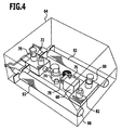
- Such a fuel supply module has in principle the same functional components as described with reference to the fuel supply module 28. It will therefore be in FIG. 4 the same reference numerals are used.
- the fuel which can be coupled out at the port 84, is set to a fixed pressure value predetermined via the pressure switch 82. Via the pressure display 86, this pressure value is displayed.
- the fuel cell device module 26 has a housing 100 (FIG. FIGS. 1 and 3 ).
- the housing is formed in particular closed with defined cooling air. For example, it is transparent.
- the fuel cell or blocks 14 are arranged. Further, in the housing 100, a fuel discharge line 102 is arranged. At this discharge line 102 sits a time-controllable (blocking) valve 104. This is in particular an electromagnetic valve. Via a pressure display 106, the pressure is displayed.
- an adjustment valve 108 may be provided, with which the pressure drop at the opening of the valve 104 can be adjusted.
- the discharge line 102 opens into an outlet port 110 through which unused fuel can be discharged.
- an oxidant discharge line 112 and in particular air discharge line is arranged in the housing 100. This opens into an outlet port 114. At the discharge line 112 is a pressure indicator 116th coupled. Further, an adjustment valve 118 is provided to adjust the volume flow of the discharged air can.
- a temperature switch 119 may be provided.
- the fuel cell device module 26 has a control signal connection 120, via which control signals can be coupled.
- the valve 104 (which is a check valve) can be activated.
- This check valve 104 is controlled to be either open or closed. It is clocked controlled and can be opened so clocked that is provided for a fuel relaxation of the fuel cell block 14 ago.
- a communication interface for the fuel cell device module 26 is formed.
- the fuel cell assembly module 26 forms a unit which is positionable as a whole separate from the other modules.
- a separate cooling device module 34 is provided which can be coupled to the fuel cell device module 26.
- a cooling device module 34 comprises one or more fans 122, via which the fuel cell block or blocks 14 can be acted upon by an air flow 124 for cooling.
- the cooling device module 34 has an electrical connection via which the corresponding energy for operating the fan or fans 122 can be coupled in (not shown in the drawing).
- a control signal connection 126 may be provided.
- the cooling device module 34 has one or more connections 128 for removing waste heat air.
- the waste heat air can then be conducted to a metal hydride storage 94 via corresponding connecting lines in order to activate it for releasing hydrogen.
- a connection is via a line which is coupled to the port 66 of the fuel supply module 28 and coupled to the interface 90 of the fuel storage module 36.
- the fuel supply module 28 communicates with the fuel cell assembly module 26 via its fuel output port 84. At an input port 132 of the fuel cell assembly module 26 fuel can be coupled. To guide the fuel between the fuel supply module 28 and the fuel cell module 26, a line 134 is provided, which is a separate element from the two modules. The cable is chosen according to the position and distance of the two modules.
- Air with atmospheric oxygen as the oxidizer can be coupled out at the output terminal 42 of the oxidizer supply module 30.
- the fuel cell device module 26 has an input port 136 through which air can be coupled.
- the ports 42 and 136 may be connected via a conduit 138, which conduit 138 is an element separate from the oxidizer supply module 30 and the fuel cell assembly module 26.
- the controller module 32 also forms a unit which as a whole is positionable independently of the other modules. It has corresponding connections 140a, 140b, 140c, 140d, via which control signals can be coupled out to modules which can be acted upon by control signals. Control signal lines 142a and so forth can be coupled to the ports to transmit the control signals.
- controller module 32 has one or more electrical energy connectors 144. From these electrical energy can be decoupled and coupled via corresponding services to corresponding power terminals of the modules. As a result, electrical consumers of the corresponding modules can then be supplied with energy.
- the fuel cell system 10 functions to firmly set feed parameters of fuel (via the fuel supply module 28) and oxidizer (via the oxidizer supply module 30), with the pressure of the fuel supplied to a fuel cell block 14 being set on the supply side , a continuous discharge of hydrogen from a fuel cell block 14 is inhibited, and an amount of fuel supplied to a fuel cell block 14 is controlled by the power consumption of an (external) load.
- control device 20 by means of the control device 20 a sequence control is formed, which transmits preset control signals.
- a control of the supply is not necessary in the described method implementation.
- a fuel cell system composed of at least positionable subsystems, namely the fuel cell device module 26, the fuel supply module 28, the oxidizer supply module 30, and the controller module 32.
- the modules have defined interfaces for communication with other modules.
- the modules are separated. In them, the corresponding functional components are fixed, so that a module can be positioned as a unit. Connecting elements and in particular lines connect together cooperating modules.
- Per module the operating parameters and in particular material flows, electrical currents and signal currents can be set separately.
- the modules can be manufactured separately.
- a safety-relevant aspect is the fuel guide in the fuel cell system 10. Due to the modular design but not the fuel cell system 10 as a whole is concerned, but only the modules in which fuel is fed, ie the fuel supply device module 28 (possibly also the fuel storage module 36) and fuel cell assembly module 26 and conduit 134. Within the fuel cell assembly module 26 and the fuel supply module 28, the fuel can, for example, lead into bores, which are formed by recesses in a solid material. There are no pipes necessary that can leak. The corresponding modules 26 and 28 can also be made gastight while the entire fuel cell system 10 no longer has to be gas-tight.
- modules 26 and 28 can be provided with a safety ventilation to the environment outside the entire system.
- the cables between modules are independent of the modules. They can be connected to the modules via safety couplings, for example, if mass transfer lines are provided.
- modules can be replaced as a whole.
- a fuel supply module and / or a fuel storage module is replaced as a whole.
- a fuel storage or fuel storage module may also form a structural element of an application.
- a metal hydride storage can be used as a supporting structural element.
- the necessary fuel is carried on board.
- the necessary oxidizer comes from the ambient air.
- a simple fuel cell system 10 is provided, which in particular is air-cooled. It can be flexibly integrated into an application due to its modular design. The company does not have to be supervised.
Abstract
Description
Die Erfindung betrifft ein Brennstoffzellensystem, umfassend eine Brennstoffzelleneinrichtung mit einem oder mehreren Brennstoffzellenblöcken, in denen chemische Energie in elektrische Energie umwandelbar ist, eine Oxidator-Versorgungseinrichtung für die Brennstoffzelleneinrichtung, eine Brennstoff-Versorgungseinrichtung für die Brennstoffzelleneinrichtung, und eine Steuerungseinrichtung.The invention relates to a fuel cell system, comprising a fuel cell device with one or more fuel cell blocks, in which chemical energy can be converted into electrical energy, an oxidizer supply device for the fuel cell device, a fuel supply device for the fuel cell device, and a control device.
Brennstoffzellensysteme, umfassend eine Brennstoffzelleneinrichtung mit einem oder mehreren Brennstoffzellenblöcken, in denen chemische Energie in elektrische Energie umwandelbar ist, eine Oxidator-Versorgungseinrichtung für die Brennstoffzelleneinrichtung, eine Brennstoff-Versorgungseinrichtung für die Brennstoffzelleneinrichtung, und eine Steuerungseinrichtung, sind beispielsweise aus der
Aus der
Aus der
Aus der
Aus der
Der Erfindung liegt die Aufgabe zugrunde, ein flexibel einsetzbares Brennstoffzellensystem bereitzustellen.The invention has for its object to provide a flexible usable fuel cell system.
Diese Aufgabe wird bei dem eingangs genannten Brennstoffzellensystem erfindungsgemäß dadurch gelöst, dass die Brennstoffzelleneinrichtung, die Oxidator-Versorgungseinrichtung, die Brennstoff-Versorgungseinrichtung und eine Kühlungseinrichtung, welche der Brennstoffzelleneinrichtung zugeordnet ist, jeweils als Modul ausgebildet sind, wobei in einem Modul die funktionellen Komponenten der jeweiligen Einrichtung in einem Gehäuse angeordnet sind, das entsprechende Modul eine Einheit bildet, welche als Ganzes positionierbar ist, das entsprechende Modul eine Kommunikationsschnittstelle mit Anschlüssen aufweist, und das Kühlungseinrichtungs-Modul mindestens einen Abwärmeluftanschluss aufweist.This object is achieved according to the invention in the fuel cell system mentioned above in that the fuel cell device, the oxidizer supply device, the fuel supply device and a cooling device, which is assigned to the fuel cell device, each designed as a module, wherein in a module, the functional components of the respective Device are arranged in a housing, the corresponding module forms a unit which is positionable as a whole, the corresponding module has a communication interface with terminals, and the cooling device module has at least one waste-heat air connection.
Durch die erfindungsgemäße Lösung lassen sich Module getrennt herstellen, einstellen und positionieren. Durch den modularen Aufbau des Brennstoffzellensystems lässt sich dieses auf flexible Weise in eine Anwendung integrieren. Insbesondere ist eine Anpassung an geometrische Gegebenheiten möglich.By means of the solution according to the invention, modules can be produced, adjusted and positioned separately. Due to the modular structure of the fuel cell system, this can be flexibly integrated into an application. In particular, an adaptation to geometric conditions is possible.
Für jedes Modul ist eine definierte Schnittstelle zur Kommunikation mit der Außenwelt bzw. anderen Modulen bezüglich Stoffaustausch (über Stoffströme) und/oder Energieaustausch und/oder Signalaustausch bereitgestellt. Dies ermöglicht es, das Brennstoffzellensystem aus Subsystemen zusammenzustellen, wobei die Subsysteme insbesondere bezüglich der jeweiligen Betriebsparameter getrennt einstellbar sind. Insbesondere lassen sich für jedes Modul die Betriebsparameter bezüglich Stoffströmen, elektrischen Strömen und Signalströmen getrennt einstellen und auch optimieren.For each module, a defined interface for communication with the outside world or other modules regarding mass transfer (via material flows) and / or energy exchange and / or signal exchange is provided. This makes it possible to assemble the fuel cell system from subsystems, wherein the subsystems are separately adjustable, in particular with regard to the respective operating parameters. In particular, the operating parameters with regard to material flows, electrical currents and signal currents can be adjusted separately and also optimized for each module.
Es ergibt sich eine einfache Zerlegbarkeit und Zusammensetzbarkeit des Brennstoffzellensystems.This results in a simple disassembly and composability of the fuel cell system.
Weiterhin lassen sich sicherheitsrelevante Komponenten getrennt ausbilden. Für die Brennstofführung ist dann nur noch das Brennstoff-Versorgungseinrichtungs-Modul und das Brennstoffzelleneinrichtungs-Modul relevant. Die anderen Module sind dann nicht mehr sicherheitsrelevant.Furthermore, safety-relevant components can be formed separately. For the fuel guide is then only the fuel supply device module and the fuel cell device module relevant. The other modules are then no longer relevant to safety.
Mit dem erfindungsgemäßen Brennstoffzellensystem lassen sich die in der
Ein entsprechendes Modul weist ein Gehäuse auf, in welchem die funktionellen Komponenten angeordnet sind. Über das Gehäuse lässt sich das Modul als Einheit ausbilden. Ferner lässt sich an dem Gehäuse eine definierte Schnittstelle und insbesondere definierte Kommunikationsschnittstelle anordnen. In dem Gehäuse sind die funktionellen Komponenten geschützt. Beispielsweise ist das Gehäuse zumindest teilweise aus einem durchsichtigen Material hergestellt, so dass Messgeräte wie Druckanzeigen abgelesen werden können.A corresponding module has a housing in which the functional components are arranged. About the housing, the module can be formed as a unit. Furthermore, a defined interface and in particular a defined communication interface can be arranged on the housing. The functional components are protected in the housing. For example, the housing is at least partially made of a transparent material so that gauges such as pressure gauges can be read.
Insbesondere sind an dem Gehäuse der oder die Anschlüsse angeordnet, über die Module untereinander oder mit entsprechenden Einrichtungen kommunizieren können.In particular, the connection or connections are arranged on the housing, via which modules can communicate with one another or with corresponding devices.
Es kann vorgesehen sein, dass das Gehäuse geschlossen ist. Dadurch werden die funktionellen Komponenten, welche in dem Gehäuse angeordnet sind, geschützt.It can be provided that the housing is closed. This protects the functional components located in the housing.
Besonders günstig ist es, wenn das Gehäuse gasdicht ist, insbesondere im Falle des Brennstoffzelleneinrichtungs-Moduls und des Brennstoff-Versorgungseinrichtungs-Moduls. Dadurch lässt sich Entweichen von Brennstoff an undefinierten Stellen vermeiden. Das System lässt sich mit einer Sicherheitsbelüftung direkt an die Umgebung versehen.It is particularly favorable if the housing is gastight, in particular in the case of the fuel cell device module and the fuel supply device module. This prevents fuel from escaping at undefined locations. The system can be provided with a safety ventilation directly to the environment.
Die Anschlüsse umfassen insbesondere Stoffanschlüsse, Signalanschlüsse und elektrische Leistungsanschlüsse. Über die Stoffanschlüsse kann ein Stoffaustausch erfolgen. Beispielsweise wird über einen Auskopplungsanschluss des Brennstoff-Versorgungseinrichtungs-Moduls Brennstoff ausgekoppelt und über einen Brennstoffeinkopplungsanschluss der Brennstoffzelleneinrichtung lässt sich in diese Brennstoff einkoppeln. Über Signalanschlüsse können Steuersignale eingekoppelt werden oder es lassen sich Steuersignale auskoppeln. Über elektrische Leistungsanschlüsse kann elektrische Leistung eingekoppelt werden oder (im Falle der Brennstoffzelleneinrichtung) ausgekoppelt werden.The connections include in particular material connections, signal connections and electrical power connections. Substances can be exchanged via the substance connections. For example, fuel is coupled out via a coupling connection of the fuel supply device module and can be coupled into this fuel via a fuel injection connection of the fuel cell device. Control signals can be injected via signal connections or control signals can be decoupled. Electrical power can be coupled in via electrical power connections or (in the case of the fuel cell device) decoupled.
Insbesondere weist das Brennstoffzelleneinrichtungs-Modul Stoffanschlüsse für Oxidator und Brennstoff und einen Anschluss zur Auskopplung elektrischer Leistung auf.In particular, the fuel cell assembly module has oxidizer and fuel attachments and a port for coupling electrical power.
Es kann auch vorgesehen sein, dass das Brennstoffzelleneinrichtungs-Modul mindestens einen Signalanschluss zur Einkopplung von Steuersignalen aufweist. Über solch einen Anschluss lassen sich beispielsweise Steuersignale einkoppeln, um ein Sperrventil getaktet zu öffnen und zu schließen, über das nicht verbrauchter Brennstoff abführbar ist.It can also be provided that the fuel cell device module has at least one signal connection for coupling control signals. By way of example, control signals can be coupled in via such a connection in order to open and close a shut-off valve via which unused fuel can be discharged.
Es ist ferner vorgesehen, dass das Brennstoff-Versorgungseinrichtungs-Modul mindestens einen Brennstoffanschluss zur Auskopplung von Brennstoff aufweist. Über diesen Brennstoffanschluss ist eine Verbindung zu der Brennstoffzelleneinrichtung herstellbar.It is further contemplated that the fuel supply module has at least one fuel port for coupling fuel. About this fuel connection, a connection to the fuel cell device can be produced.
Es kann auch vorgesehen sein, dass das Brennstoff-Versorgungseinrichtungs-Modul mindestens einen Signalanschluss aufweist.It may also be provided that the fuel supply device module has at least one signal connection.
Es ist ferner vorgesehen, dass das Oxidator-Versorgungseinrichtungs-Modul mindestens einen Oxidatoranschluss zur Auskopplung von Oxidator aufweist. Es lässt sich dadurch Luft mit Luftsauerstoff als Oxidator auskoppeln. Über diesen Anschluss lässt sich die Verbindung mit einer Brennstoffzelleneinrichtung herstellen.It is further contemplated that the oxidizer supply module has at least one oxidizer port for coupling oxidizer. It can thereby decouple air with atmospheric oxygen as an oxidizer. This connection can be used to connect to a fuel cell device.
Es kann auch vorgesehen sein, dass das Oxidator-Versorgungseinrichtungs-Modul mindestens einen Signalanschluss aufweist, über den insbesondere Steuerungssignale einkoppelbar sind.It can also be provided that the oxidizer supply device module has at least one signal connection via which, in particular, control signals can be coupled in.
Ganz besonders vorteilhaft ist es, wenn kommunizierende Module über Leitungen verbunden sind. Die Module lassen sich an einer Anwendung zunächst getrennt und unabhängig voneinander positionieren. Die notwendigen Kommunikationsverbindungen bezüglich Stofftransport, Zuführung von elektrischer Leistung und bezüglich Steuerungssignalen werden dann nachträglich entsprechend der geometrischen Gegebenheiten hergestellt. Es ergibt sich dadurch ein flexibler Aufbau, wobei das erfindungsgemäße Brennstoffzellensystem über Subsysteme gebildet ist.It is particularly advantageous if communicating modules are connected via lines. The modules can first be separated and positioned independently of each other on an application. The necessary communication connections with regard to material transport, supply of electrical power and with respect to control signals are then produced subsequently according to the geometric conditions. This results in a flexible structure, wherein the fuel cell system according to the invention is formed by subsystems.
Insbesondere sind die Leitungen von dem oder den Modulen getrennte Elemente.In particular, the lines of the module (s) are separate elements.
Es kann vorgesehen sein, dass ein oder mehrere Brennstoffspeicher in das Brennstoff-Versorgungseinrichtungs-Modul integriert sind. Wenn ein Brennstoffspeicher entleert ist, dann wird beispielsweise das Brennstoff-Versorgungseinrichtungs-Modul als Ganzes ausgetauscht.It may be provided that one or more fuel reservoirs are integrated into the fuel supply module. For example, if a fuel storage is deflated, then the fuel supply module is replaced as a whole.
Es kann auch vorgesehen sein, dass mindestens ein Brennstoffspeicher vorgesehen ist, welcher an die Brennstoffversorgungseinrichtung gekoppelt ist und insbesondere ein externes Element bezogen auf ein Brennstoff-Versorgungseinrichtungs-Modul bildet.It can also be provided that at least one fuel storage is provided, which is coupled to the fuel supply device and in particular forms an external element with respect to a fuel supply device module.
Es können auch ein oder mehrere Brennstoffspeicher-Module vorgesehen sein. Ein Brennstoffspeicher-Modul lässt sich an ein Brennstoff-Versorgungseinrichtungs-Modul ankoppeln. Wenn ein Brennstoffspeicher entleert ist, dann kann ein entsprechendes Brennstoffspeicher-Modul auf einfache Weise ausgetauscht werden.It can also be provided one or more fuel storage modules. A fuel storage module may be coupled to a fuel supply module. If a fuel storage is drained, then a corresponding fuel storage module can be easily replaced.
Ganz besonders vorteilhaft ist es, wenn der mindestens eine Brennstoffspeicher oder das mindestens eine Brennstoffspeicher-Modul als strukturelles Element des Brennstoffzellensystems oder einer Anwendung ausgebildet ist. Dadurch lässt sich die Energieversorgungseinrichtung der Anwendung, welche mit Hilfe des Brennstoffzellensystems gebildet ist, platzsparend ausbilden.It is particularly advantageous if the at least one fuel storage or the at least one fuel storage module is designed as a structural element of the fuel cell system or an application. As a result, the energy supply device of the application, which is formed with the aid of the fuel cell system, can save space.
Insbesondere ist der mindestens eine Brennstoffspeicher oder das mindestens eine Brennstoffspeicher-Modul ein Metallhydridspeicher oder umfasst einen solchen. In einem Metallhydridspeicher ist Wasserstoff nicht als freies Gas gespeichert, sonder in gebundener Form. Beispielsweise über Erhitzung lässt sich Wasserstoff aus einem solchen Metallhydridspeicher austreiben. Es treten dabei nicht die Sicherheitsprobleme auf wie bei der Wasserstoffspeicherung in einem Drucktank. Ein Metallhydridspeicher ist ein massives Element, welches entsprechend als strukturelles Element und beispielsweise als tragendes Element für eine Anwendung genutzt werden kann.In particular, the at least one fuel storage or the at least one fuel storage module is or comprises a metal hydride storage. In a metal hydride storage, hydrogen is not stored as free gas, but in bound form. For example, by heating, hydrogen can be driven out of such a metal hydride storage. It does not occur the security problems as in the hydrogen storage in a pressure tank. A metal hydride reservoir is a solid element that can be used as a structural element and, for example, as a structural element for an application.
Insbesondere ist der mindestens eine Brennstoffspeicher mittels eines oder mehreren Strangpressprofilen gebildet. Entsprechende Metallhydridspeicher sind beispielsweise unter der Bezeichnung MH Hydrogene Storage Tank von SUMITOMO PRECISION PRODUCTS CO., LTD., Japan, erhältlich.In particular, the at least one fuel storage is formed by means of one or more extruded profiles. Corresponding metal hydride reservoirs are available, for example, under the name MH Hydrogene Storage Tank from SUMITOMO PRECISION PRODUCTS CO., LTD., Japan.
Der Brennstoffzelleneinrichtung ist eine Kühlungseinrichtung zugeordnet. Dadurch lässt sich diese mit einem optimierten Wirkungsgrad betreiben.The fuel cell device is associated with a cooling device. As a result, they can be operated with optimized efficiency.
Ganz besonders vorteilhaft ist es, wenn die Kühlungseinrichtung so angeordnet und ausgebildet ist, dass mindestens ein Brennstoffspeicher mit Abwärmeluft beaufschlagbar ist. Die Abwärmeluft kann dann dazu genutzt werden, beispielsweise aus einem Metallhydridspeicher Wasserstoff auszutreiben. Dadurch lässt sich der Wirkungsgrad des Brennstoffzellensystems verbessern.It is particularly advantageous if the cooling device is arranged and designed such that at least one fuel reservoir can be acted upon by waste-heat air. The waste heat air can then be used to expel hydrogen, for example from a metal hydride storage. As a result, the efficiency of the fuel cell system can be improved.
Es ist grundsätzlich möglich, dass die Kühlungseinrichtung mit der Brennstoffzelleneinrichtung in einem Brennstoffzelleneinrichtungs-Modul integriert ist. Erfindungsgemäß ist die Kühlungseinrichtung als Modul ausgebildet.It is basically possible for the cooling device to be integrated with the fuel cell device in a fuel cell module. According to the invention, the cooling device is designed as a module.
Das Kühlungseinrichtungs-Modul weist mindestens einen Abwärmeluftanschluss auf. An diesem Anschluss lässt sich Abwärme auskoppeln, um diese beispielsweise einem Metallhydridspeicher zuzuführen.The refrigerator module has at least one waste air outlet. At this connection, waste heat can be decoupled, for example, to supply them to a metal hydride storage.
Günstig ist es, wenn das Kühlungseinrichtungs-Modul mindestens einen Signalanschluss aufweist. Beispielsweise kann dann die entsprechende Kühlungseinrichtung über Steuerungssignale so gesteuert werden, dass sich eine optimale Kühlungswirkung ergibt.It is advantageous if the cooling device module has at least one signal connection. For example, the corresponding cooling device can then be controlled via control signals in such a way that an optimum cooling effect results.
Es kann auch vorgesehen sein, dass die Steuerungseinrichtung als Modul ausgebildet ist. Die Steuerungseinrichtung bildet dann eine eigene Komponente des Brennstoffzellensystems. Insbesondere ist eine zentrale Steuerungseinrichtung realisiert.It can also be provided that the control device is designed as a module. The control device then forms a separate component of the fuel cell system. In particular, a central control device is realized.
Günstigerweise ist mittels der Steuerungseinrichtung eine Ablaufsteuerung gebildet, welche voreingestellte Steuerungssignale sendet. Es erfolgt keine Regelung der Brennstoffzuführung und Oxidatorzuführung zu der Brennstoffzelleneinrichtung, sondern höchstens eine Steuerung. Ein entsprechendes Verfahren ist in der
Günstig ist es, wenn elektrische Verbraucher des Brennstoffzellensystems über die Steuerungseinrichtung mit elektrischer Energie versorgt sind. Die Steuerungseinrichtung stellt dann eine definierte Schnittstelle bereit, über die die entsprechenden Module die elektrische Energie in der erforderlichen Form erhalten können.It is advantageous if electrical consumers of the fuel cell system are supplied with electrical energy via the control device. The control device then provides a defined interface, via which the corresponding modules can obtain the electrical energy in the required form.
Günstig ist es, wenn die Betriebsparameter bezüglich Stoffströmen, elektrischer Strömen und Signalströmen für jedes Modul unabhängig einstellbar sind und/oder eingestellt sind. Dadurch ergibt sich bei einfacher Herstellbarkeit eine optimierte Anpassbarkeit des Brennstoffzellensystems an Anwendungen. Jedes Modul lässt sich dabei getrennt optimieren.It is favorable if the operating parameters with regard to material flows, electrical currents and signal currents can be set independently for each module and / or are set. This results in ease of manufacture an optimized adaptability of the fuel cell system to applications. Each module can be optimized separately.
Besonders vorteilhaft ist es, wenn in dem Brennstoff-Versorgungseinrichtungs-Modul und/oder Oxidator-Versorgungseinrichtungs-Modul und/oder Brennstoffzelleneinrichtungs-Modul Stofführungen mittels einer Bohrung gebildet sind, wobei diese Bohrung insbesondere durch eine Ausnehmung in einem Vollmaterial hergestellt ist. Dadurch lässt sich innerhalb eines solchen Moduls eine Art von Stofftransport-Bus bereitstellen. Es muss dann keine Rohrführung vorgesehen sein. Insbesondere wenn Brennstoff geführt wird, ist dadurch die Gefahr von Lecks stark verringert. Ein Modul weist beispielsweise ein blockförmiges Kunststoffgehäuse auf. In einem solchen blockförmigen Kunststoffgehäuse lässt sich über eine Bohrung eine Stofführung ausbilden.It is particularly advantageous if in the fuel supply device module and / or oxidizer supply module and / or fuel cell module module cloth guides are formed by means of a bore, which hole is made in particular by a recess in a solid material. This makes it possible to provide a type of mass transfer bus within such a module. It must then be provided no pipe guide. In particular, when fuel is conducted, thereby the risk of leaks is greatly reduced. A module has, for example, a block-shaped plastic housing. In such a block-shaped plastic housing can be formed via a hole a cloth guide.
Ganz besonders vorteilhaft ist es, wenn für die Oxidator-Versorgungseinrichtung der Druck und der Volumenstrom von auskoppelbarer Luft als Oxidatorträger fest vorgegeben ist. Dadurch lässt sich ein einfach arbeitendes Brennstoffzellensystem ausbilden, wie es in der
Aus dem gleichen Grund ist es vorteilhaft, wenn für die Brennstoff-Versorgungseinrichtung der Druck auskoppelbaren Brennstoffs fest eingestellt ist.For the same reason, it is advantageous if the pressure outputable fuel is set for the fuel supply device.
Insbesondere ist für die Brennstoff-Versorgungseinrichtung die Druckdifferenz für auskoppelbaren Brennstoff in Relation zu von der Oxidator-Versorgungseinrichtung auskoppelbarer Luft als Oxidatorträger fest eingestellt. Eine entsprechende Verfahrensführung ist in der
Ganz besonders vorteilhaft ist es, wenn eine Mengenregelung des der Brennstoffzelleneinrichtung zugeführten Brennstoffs durch die elektrische Leistungsaufnahme eines Verbrauchers erfolgt. Dadurch ergibt sich eine einfache Steuerung und Regelung des Brennstoffzellensystems, da der Verbraucher die Brennstoffzuführung "automatisch" regelt.It is particularly advantageous if a quantity control of the fuel supplied to the fuel cell device is effected by the electrical power consumption of a consumer. This results in a simple Control and regulation of the fuel cell system, as the consumer regulates the fuel supply "automatically".
Die nachfolgende Beschreibung bevorzugter Ausführungsformen dient im Zusammenhang mit der Zeichnung der näheren Erläuterung der Erfindung. Es zeigen:
- Figur 1
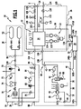
- eine schematische Darstellung eines Ausführungsbeispiels eines erfindungsgemäßen Brennstoffzellensystems in Modulbauweise;
- Figur 2
- ein Ausführungsbeispiel eines Oxidator-Versorgungseinrichtungs-Moduls;
- Figur 3
- ein Ausführungsbeispiel eines Brennstoffzelleneinrichtungs-Moduls;
- Figur 4
- ein Ausführungsbeispiel eines Brennstoff-Versorgungseinrichtungs-Moduls und
- Figur 5
- ein Ausführungsbeispiel eines Brennstoffspeicher-Moduls.
- FIG. 1
- a schematic representation of an embodiment of a fuel cell system according to the invention in modular design;
- FIG. 2
- an embodiment of an oxidizer supply module;
- FIG. 3
- an embodiment of a fuel cell assembly module;
- FIG. 4
- an embodiment of a fuel supply device module and
- FIG. 5
- an embodiment of a fuel storage module.
Ein Ausführungsbeispiel eines erfindungsgemäßen Brennstoffzellensystems, welches in
Weiterhin umfasst das Brennstoffzellensystem 10 eine Oxidator-Versorgungseinrichtung 18 für die Brennstoffzelleneinrichtung 12, mittels der dem oder den Brennstoffzellenblöcken 14 Oxidator bereitstellbar ist.Furthermore, the
Zur Steuerung des Brennstoffzellensystems 10 ist eine Steuerungseinrichtung 20 vorgesehen.For controlling the
Dem oder den Brennstoffzellenblöcken 14 kann eine Kühlungseinrichtung 22 zugeordnet sein.The one or more fuel cell blocks 14 may be associated with a
Bei den Brennstoffzellen des oder der Brennstoffzellenblöcke 14 handelt es sich insbesondere um Polymermembran-Brennstoffzellen (PEFC), bei denen der Elektrolyt durch eine protonenleitende Membran gebildet ist. Neben der Funktion des Elektrolyten ist die Membran auch Katalysatorträger für die anodischen und kathodischen Elektrokatalysatoren und dient als Separator für die gasförmigen Reaktanten. Als Brennstoff wird Wasserstoff eingesetzt und als Oxidator Sauerstoff und insbesondere Luftsauerstoff. Der Brennstoffzelleneinrichtung 12 wird dann Luft mit Luftsauerstoff als Oxidator zugeführt.The fuel cells of the fuel cell block or blocks 14 are, in particular, polymer membrane fuel cells (PEFC), in which the electrolyte is formed by a proton-conducting membrane. In addition to the function of the electrolyte, the membrane is also catalyst support for the anodic and cathodic electrocatalysts and serves as a separator for the gaseous reactants. As fuel, hydrogen is used and as an oxidizer oxygen and in particular atmospheric oxygen. The
In dem oder den Brennstoffzellenblöcken 14 wird chemische Energie durch die kalte Verbrennung des Brennstoffs mit dem Oxidator in elektrische Energie umgewandelt. Diese elektrische Energie ist über einen Anschluss 24 an einen Verbraucher abgebbar.In the fuel cell block (s) 14, chemical energy is converted to electrical energy by the cold combustion of the fuel with the oxidizer. This electrical energy can be delivered via a
Das Brennstoffzellensystem 10 ist modular aufgebaut mit einem Brennstoffzelleneinrichtungs-Modul 26, einem Brennstoff-Versorgungseinrichtungs-Modul 28 und einem Oxidator-Versorgungseinrichtungs-Modul 30.The
Ferner ist ein Steuerungseinrichtungs-Modul 32 vorgesehen, welches die Steuerungseinrichtung 20 umfasst.Furthermore, a
Die Kühlungseinrichtung 22 ist in ein Kühlungseinrichtungs-Modul 34 integriert.The
Bei dem gezeigten Ausführungsbeispiel ist ein Brennstoffspeicher-Modul 36 vorgesehen.In the embodiment shown, a
Es ist alternativ auch möglich, dass Brennstoffspeicher in das Brennstoff-Versorgungseinrichtungs-Modul 28 integriert sind.Alternatively, it is also possible for fuel storage to be integrated with the
In das Oxidator-Versorgungseinrichtungs-Modul 30 (
Das Oxidator-Versorgungseinrichtungs-Modul 30 ist mit einer Kommunikationsschnittstelle 40 versehen, welche einen Ausgangsanschluss 42 aufweist, über den Oxidator auskoppelbar ist. Insbesondere ist Luft als Oxidatorträger mit Luftsauerstoff als Oxidator auskoppelbar.The
Ferner ist ein elektrischer Anschluss 44 vorgesehen, über den elektrische Energie in das Oxidator-Versorgungseinrichtungs-Modul 30 zur Bereitstellung an elektrische Verbraucher dieses Moduls einkoppelbar ist.Furthermore, an
Weiterhin kann ein Signalanschluss 46 zur Einkopplung von Steuerungssignalen vorgesehen sein.Furthermore, a
Die entsprechenden Anschlüsse 42, 44 und 46 sind an dem Gehäuse 38 angeordnet.The
In dem Gehäuse 38 ist ein Luftverdichter 48 angeordnet. Diesem ist ein Filter 50 vorgeschaltet. Das Gehäuse 38 weist eine oder mehrere Luftzuführungsöffnungen 52 auf, über die Luft dem Luftverdichter 48 zuführbar ist, wobei der Filter 50 durch die zugeführte Luft passiert werden muss. An der oder den Luftzuführungsöffnungen 52 ist ein Luftförderer und Kühler 54 angeordnet, welcher insbesondere über einen Elektromotor angetrieben ist.In the
In dem Gehäuse 38 ist dem Luftverdichter 48 ein Wasserabscheider 56 nachgeschaltet. Über diesen Wasserabscheider 56 lässt sich durch das Oxidator-Versorgungseinrichtungs-Modul 30 durchgeführte Luft entfeuchten. Dem Wasserabscheider 56 ist dabei ein Stellelement 58 zugeordnet, welches in Verbindung mit einem Ausgang steht, über den Wasser abgelassen werden kann.In the
Ferner umfasst das Oxidator-Versorgungseinrichtungs-Modul 30 einen Druckschalter 60 und eine Druckanzeige 62. Mittels des Druckschalters 60 lässt sich ein bestimmter Luftstrom des Luftverdichters 48 überprüfen. Dieser Luftstrom wird durch eine Stellvorrichtung (wie beispielsweise das Einstellventil 118) fest vorgegeben. Der Luftstrom lässt sich an dem Ausgangsanschluss 42 auskoppeln.Further, the
Für die Einstellung des Versorgungseinrichtungs-Moduls 30 kann eine Stellvorrichtung auch direkt an das Modul 30 angeschlossen und/oder nur vorübergehend angeschlossen werden.For the adjustment of the
Das Oxidator-Versorgungseinrichtungs-Modul 38 bildet eine als Ganzes positionierbare Einheit. Die Verbindung mit dem Steuereinrichtungs-Modul 32 erfolgt über die Kommunikationsschnittstelle 40. Die Verbindung mit dem Brennstoffzelleneinrichtungs-Modul 26 erfolgt über den Anschluss 42 (als Stoffstrom-Schnittstelle). Elektrische Verbraucher des Oxidator-Versorgungseinrichtungs-Moduls 30 werden über das Steuereinrichtungs-Modul 32 mit elektrischer Energie (die an dem elektrischen Anschluss 44 eingekoppelt wird) versorgt.The
Das Brennstoff-Versorgungseinrichtungs-Modul 28 weist ein Gehäuse 64 auf, in welchem die funktionellen Komponenten der Brennstoff-Versorgungseinrichtung 16 angeordnet sind. Das Gehäuse 64 ist insbesondere geschlossen und gasdicht ausgebildet. Es ist vorzugsweise vorgesehen, dass Führungen für Brennstoff innerhalb des Brennstoff-Versorgungseinrichtungs-Moduls 28 rohrfrei ausgebildet sind. Beispielsweise ist das Gehäuse 64 mittels eines Plexiglasblocks gebildet und die entsprechenden Strömungsführungen sind durch Bohrungen in dem Plexiglasblock gebildet. Es wird dadurch eine Art von Bussystem für die Strömungsführung des Brennstoffs innerhalb des Brennstoff-Versorgungseinrichtungs-Moduls 28 bereitgestellt.The
Bei dem in
Auf die Flammensperre 76 folgend ist ein Ablassventil 78 in der Brennstoffführung 68 angeordnet. Über das Ablassventil 78 lässt sich in dem Gehäuse 64 befindlicher gasförmiger Brennstoff auskoppeln.Following the
Weiterhin ist ein weiteres Sicherheitsventil 80 vorgesehen.Furthermore, a
Über einen weiteren Druckschalter 82 lässt sich der Druck von an einem Anschluss 84 auskoppelbaren Brennstoff überprüfen. Über eine Druckanzeige 86 ist dieser Druck anzeigbar.Another
Das Brennstoff-Versorgungseinrichtungs-Modul 28 weist eine Kommunikationsschnittstelle auf, welche die Anschlüsse 66 und 84 umfasst. Weiterhin kann ein Steuersignalanschluss 88 vorgesehen sein. Für die Einkopplung von elektrischer Energie zur Bereitstellung an elektrische Verbraucher des Brennstoff-Versorgungseinrichtungs-Moduls 28 kann ein elektrischer Anschluss vorgesehen sein (in
Das Brennstoff-Versorgungseinrichtungs-Modul 28 bildet eine Einheit, welche als Ganzes positionierbar ist.The
Das Brennstoffspeicher-Modul 36 weist eine Schnittstelle 90 auf, über welche Brennstoff auskoppelbar ist und insbesondere dem Brennstoff-Versorgungseinrichtungs-Modul 28 zuführbar ist. Das Brennstoffspeicher-Modul 36 weist einen oder mehrere Brennstoffspeicher 92 auf, in denen beispielsweise Wasserstoff gasförmig gespeichert ist.The
Es können auch ein oder mehrere Metallhydridspeicher 94 (
Ein solcher Metallhydridspeicher 94 kann ein strukturelles Element des Brennstoffzellensystems 10 oder einer Anwendung sein. Da der Metallhydridspeicher 94 mit seinem Strangpressprofil 96 mechanisch belastbar ist, kann er auch eine tragende Funktion beispielsweise in einem Fahrzeug übernehmen, um Fahrzeugteile abzustützen oder das Brennstoffzellensystem 10 mit seinen Modulen zu halten oder einzelne Module des Brennstoffzellensystems 10 zu halten.Such a
Das Brennstoffspeicher-Modul 36 ist insbesondere so angeordnet und ausgebildet, dass es austauschbar ist. Nach der Entleerung kann es dann entnommen werden und es kann ein neues Brennstoffspeicher-Modul 36 eingesetzt werden mit gefülltem Brennstoffspeicher 92 bzw. gefüllten Brennstoffspeichern 92.The
Es ist auch möglich, wie in
Es ist insbesondere vorgesehen, dass der Brennstoff, welcher an dem Anschluss 84 auskoppelbar ist, auf einen über den Druckschalter 82 vorgegebenen festen Druckwert eingestellt ist. Über die Druckanzeige 86 wird dieser Druckwert angezeigt.It is provided in particular that the fuel, which can be coupled out at the
Das Brennstoffzelleneinrichtungs-Modul 26 weist ein Gehäuse 100 auf (
In dem Gehäuse 100 sind der oder die Brennstoffzellenblöcke 14 angeordnet. Ferner ist in dem Gehäuse 100 eine Brennstoff-Abführungsleitung 102 angeordnet. An dieser Abführungsleitung 102 sitzt ein zeitlich steuerbares (Sperr-)Ventil 104. Bei diesem handelt es sich insbesondere um ein elektromagnetisches Ventil. Über eine Druckanzeige 106 wird der Druck angezeigt.In the
Weiterhin kann ein Einstellventil 108 vorgesehen sein, mit dem der Druckabfall bei Öffnung des Ventils 104 eingestellt werden kann.Furthermore, an
Die Abführungsleitung 102 mündet in einen Ausgangsanschluss 110, über den nicht verbrauchter Brennstoff abführbar ist.The
In dem Gehäuse 100 ist auch eine Oxidator-Abführungsleitung 112 und insbesondere Luft-Abführungsleitung angeordnet. Diese mündet in einen Ausgangsanschluss 114. An der Abführungsleitung 112 ist eine Druckanzeige 116 gekoppelt. Ferner ist ein Einstellventil 118 vorgesehen, um den Volumenstrom der abgeführten Luft einstellen zu können.In the
An der Abführungsleitung 112 kann ein Temperaturschalter 119 vorgesehen sein.At the
Das Brennstoffzelleneinrichtungs-Modul 26 weist einen Steuersignalanschluss 120 auf, über den Steuersignale einkoppelbar sind. Insbesondere ist dabei das Ventil 104 (welches ein Sperrventil ist) ansteuerbar. Dieses Sperrventil 104 wird so gesteuert, dass es entweder offen oder geschlossen ist. Es ist getaktet steuerbar und kann dabei so getaktet geöffnet werden, dass für eine Brennstoffentspannung von dem Brennstoffzellenblock 14 her gesorgt ist.The fuel
Der Anschluss 24, über welchen externe elektrische Verbraucher mit elektrischer Leistung versorgt sind, ist an dem Gehäuse 100 angeordnet.The terminal 24, via which external electrical consumers are supplied with electrical power, is arranged on the
Es können auch elektrische Anschlüsse vorgesehen sein (in der
Über die beschriebenen Anschlüsse ist eine Kommunikationsschnittstelle für das Brennstoffzelleneinrichtungs-Modul 26 gebildet.About the described connections, a communication interface for the fuel
Das Brennstoffzelleneinrichtungs-Modul 26 bildet eine Einheit, die als Ganzes getrennt von den anderen Modulen positionierbar ist.The fuel
Es ist ein separates Kühlungseinrichtungs-Modul 34 vorgesehen, welches an das Brennstoffzelleneinrichtungs-Modul 26 koppelbar ist.A separate cooling device module 34 is provided which can be coupled to the fuel
Beispielsweise umfasst ein Kühlungseinrichtungs-Modul 34 einen oder mehrere Lüfter 122, über welche der oder die Brennstoffzellenblöcke 14 mit einem Luftstrom 124 zur Kühlung beaufschlagbar sind. Das Kühlungseinrichtungs-Modul 34 weist einen elektrischen Anschluss auf, über den entsprechende Energie zum Betreiben des oder der Lüfter 122 einkoppelbar ist (in der Zeichnung nicht gezeigt). Ferner kann ein Steuersignalanschluss 126 vorgesehen sein.For example, a cooling device module 34 comprises one or
Günstig ist es, wenn das Kühlungseinrichtungs-Modul 34 einen oder mehrere Anschlüsse 128 zur Abführung von Abwärmeluft aufweist. Beispielsweise kann dann über entsprechende Verbindungsleitungen die Abwärmeluft an einen Metallhydridspeicher 94 geführt werden, um diesen zur Wasserstoffabgabe zu aktivieren.It is advantageous if the cooling device module 34 has one or
Bei der erfindungsgemäßen Lösung sind das Brennstoffzelleneinrichtungs-Modul 26, das Brennstoff-Versorgungseinrichtungs-Modul 28, das Oxidator-Versorgungseinrichtungs-Modul 30 und das Steuerungseinrichtungs-Modul 32 getrennt und unabhängig voneinander positionierbar. Die Kommunikation untereinander erfolgt über die entsprechenden Schnittstellen:
- Zur direkten Ankopplung des Brennstoffspeicher-
Moduls 36 istbeispielsweise eine Kupplung 130 und insbesondere eine Schnellkupplung vorgesehen. Eine Brennstoffleitung ist dann über diese Kupplung gebildet.
- For direct coupling of the
fuel storage module 36, for example, a clutch 130 and in particular a quick coupling is provided. A fuel line is then formed via this coupling.
Es ist auch möglich, dass eine Verbindung über eine Leitung erfolgt, welche an den Anschluss 66 der Brennstoff-Versorgungseinrichtungs-Moduls 28 angekoppelt wird und an die Schnittstelle 90 des Brennstoffspeicher-Moduls 36 angekoppelt wird.It is also possible that a connection is via a line which is coupled to the
Das Brennstoff-Versorgungseinrichtungs-Modul 28 kommuniziert mit dem Brennstoffzelleneinrichtungs-Modul 26 über seinen Ausgangsanschluss 84 für Brennstoff. An einem Eingangsanschluss 132 des Brennstoffzelleneinrichtungs-Moduls 26 kann Brennstoff eingekoppelt werden. Zur Führung des Brennstoffs zwischen dem Brennstoff-Versorgungseinrichtungs-Modul 28 und dem Brennstoffzelleneinrichtungs-Modul 26 ist eine Leitung 134 vorgesehen, welche ein von den beiden Modulen getrenntes Element ist. Die Leitung wird je nach Position und Abstand der beiden Module gewählt.The
Luft mit Luftsauerstoff als Oxidator lässt sich an dem Ausgangsanschluss 42 des Oxidator-Versorgungseinrichtungs-Moduls 30 auskoppeln. Das Brennstoffzelleneinrichtungs-Modul 26 weist einen Eingangsanschluss 136 auf, über den sich Luft einkoppeln lässt. Die Anschlüsse 42 und 136 lassen sich über eine Leitung 138 verbinden, wobei diese Leitung 138 ein von dem Oxidator-Versorgungseinrichtungs-Modul 30 und dem Brennstoffzelleneinrichtungs-Modul 26 getrenntes Element ist.Air with atmospheric oxygen as the oxidizer can be coupled out at the
Das Steuerungseinrichtungs-Modul 32 bildet ebenfalls eine Einheit, welche als Ganzes unabhängig von den anderen Modulen positionierbar ist. Es weist entsprechende Anschlüsse 140a, 140b, 140c, 140d auf, über die Steuersignale an mit Steuersignalen beaufschlagbare Module auskoppelbar sind. An die Anschlüsse lassen sich Steuersignalleitungen 142a usw. koppeln, um die Steuersignale übertragen zu können.The
Ferner weist das Steuerungseinrichtungs-Modul 32 einen oder mehrere Anschlüsse 144 für elektrische Energie auf. Aus diesen lässt sich elektrische Energie auskoppeln und über entsprechende Leistungen an entsprechende Energieanschlüsse der Module koppeln. Dadurch lassen sich elektrische Verbraucher der entsprechenden Module dann mit Energie versorgen.Furthermore, the
Das Brennstoffzellensystem 10 funktioniert so, dass Zuführungsparameter von Brennstoff (über das Brennstoff-Versorgungseinrichtungs-Modul 28) und Oxidator (über das Oxidator-Versorgungseinrichtungs-Modul 30) fest vorgegeben werden, wobei auf der Zuführungsseite der Druck des einem Brennstoffzellenblock 14 zugeführten Brennstoffs vorgegeben wird, eine kontinuierliche Wasserstoffabführung aus einem Brennstoffzellenblock 14 gesperrt wird und eine Menge des einem Brennstoffzellenblock 14 zugeführten Brennstoffs durch die Leistungsaufnahme eines (externen) Verbrauchers geregelt wird.The
Ein solches Verfahren sowie weitere Verfahrensdetails und die detaillierte Ausbildung des entsprechenden Brennstoffzellensystems sind in der
Insbesondere ist mittels der Steuerungseinrichtung 20 eine Ablaufsteuerung gebildet, welche voreingestellte Steuerungssignale sendet. Eine Regelung der Zuführung ist bei der beschriebenen Verfahrensdurchführung nicht notwendig.In particular, by means of the control device 20 a sequence control is formed, which transmits preset control signals. A control of the supply is not necessary in the described method implementation.
Erfindungsgemäß wird ein Brennstoffzellensystem bereitgestellt, welches aus mindestens bezüglich der Positionierbarkeit unabhängigen Subsystemen zusammengesetzt ist, nämlich dem Brennstoffzelleneinrichtungs-Modul 26, dem Brennstoff-Versorgungseinrichtungs-Modul 28, dem Oxidator-Versorgungseinrichtungs-Modul 30 und dem Steuerungseinrichtungs-Modul 32.According to the invention, there is provided a fuel cell system composed of at least positionable subsystems, namely the fuel
Die Module weisen definierte Schnittstellen zur Kommunikation mit anderen Modulen auf. Die Module sind getrennt. In ihnen sind die entsprechenden funktionellen Komponenten fest angeordnet, so dass ein Modul als Einheit positionierbar ist. Verbindungselemente und insbesondere Leitungen verbinden miteinander kooperierende Module.The modules have defined interfaces for communication with other modules. The modules are separated. In them, the corresponding functional components are fixed, so that a module can be positioned as a unit. Connecting elements and in particular lines connect together cooperating modules.
Pro Modul lassen sich die Betriebsparameter und insbesondere Stoffströme, elektrische Ströme und Signalströme separat einstellen.Per module, the operating parameters and in particular material flows, electrical currents and signal currents can be set separately.
Die Module lassen sich getrennt herstellen.The modules can be manufactured separately.
Ein sicherheitsrelevanter Aspekt ist die Brennstofführung in dem Brennstoffzellensystem 10. Durch die Modulbauweise ist aber nicht das Brennstoffzellensystem 10 als Ganzes betroffen, sondern nur die Module, in denen Brennstoff geführt wird, d. h. das Brennstoff-Versorgungseinrichtungs-Modul 28 (gegebenenfalls auch das Brennstoffspeicher-Modul 36) sowie das Brennstoffzelleneinrichtungs-Modul 26 und die Leitung 134. Innerhalb des Brennstoffzelleneinrichtungs-Moduls 26 und des Brennstoff-Versorgungseinrichtungs-Moduls 28 lässt sich der Brennstoff beispielsweise in Bohrungen führen, welche durch Ausnehmungen in einem Vollmaterial gebildet sind. Es sind dadurch keine Rohre notwendig, die leckschlagen können. Auch lassen sich die entsprechenden Module 26 und 28 gasdicht ausbilden, während das gesamte Brennstoffzellensystem 10 dann nicht mehr gasdicht ausgebildet werden muss.A safety-relevant aspect is the fuel guide in the
Weiterhin lassen sich die Module 26 und 28 mit einer Sicherheitsbelüftung an die Umgebung außerhalb des Gesamtsystems versehen.Furthermore, the
Durch die Modularisierung des Brennstoffzellensystems 10 lässt sich dieses flexibel aufbauen. Insbesondere ist eine Anpassung an geometrische Gegebenheiten möglich. Weiterhin lässt sich jedes Modul für sich optimieren.Due to the modularization of the
Die Leitungen zwischen Modulen sind unabhängig von den Modulen. Sie lassen sich beispielsweise über Sicherheitskupplungen, wenn Stofftransportleitungen vorgesehen sind, an die Module anschließen.The cables between modules are independent of the modules. They can be connected to the modules via safety couplings, for example, if mass transfer lines are provided.
Auch eine leichte Reparatur oder Austausch von Komponenten des Brennstoffzellensystems 10 ist möglich, da Module als Ganzes ausgetauscht werden können. Beispielsweise wird ein Brennstoff-Versorgungseinrichtungs-Modul und/oder ein Brennstoffspeicher-Modul als Ganzes ausgetauscht.Even a slight repair or replacement of components of the
Weiterhin ergibt sich auch eine leichte Zerlegbarkeit und Zusammensetzbarkeit des Brennstoffzellensystems 10.Furthermore, an easy disassembly and assemblability of the
Insbesondere wenn Metallhydridspeicher 94 eingesetzt werden, dann kann ein Brennstoffspeicher oder ein Brennstoffspeicher-Modul auch ein strukturelles Element einer Anwendung bilden. Insbesondere kann ein solcher Metallhydridspeicher als tragendes Strukturelement eingesetzt werden. Der nötige Brennstoff wird dabei "on board" mitgeführt. Der notwendige Oxidator stammt aus der Umgebungsluft.In particular, when
Erfindungsgemäß wird ein einfaches Brennstoffzellensystem 10 bereitgestellt, welches insbesondere luftgekühlt ist. Es lässt sich auf flexible Weise aufgrund seines modularen Aufbaus in eine Anwendung integrieren. Der Betrieb muss nicht beaufsichtigt werden.According to the invention, a simple
Claims (15)
- Fuel cell system comprising a fuel cell device (12) having one or more fuel cell blocks (14) in which chemical energy is convertible into electrical energy, an oxidant supply device (18) for the fuel cell device (12), a fuel supply device (16) for the fuel cell device (12), and a control device (20), wherein the fuel cell device (12), the oxidant supply device (18), the fuel supply device (16) and a cooling device (22) which is associated with the fuel cell device (12) are each configured as a module (26; 30; 28; 34), wherein in a module (26; 30; 28; 34), the functional components of the respective device (12; 18; 16; 22) are disposed in a housing (100; 38; 64), wherein the corresponding module (26; 30; 28; 34) forms a unit which is positionable as a whole, wherein the corresponding module (26; 30; 28; 34) has a communication interface (40) with connectors (24, 114, 120, 132, 136; 66, 84; 42, 44, 46; 126, 128) and the cooling device module (34) has at least one connector (128) for air conveying waste heat.
- Fuel cell system in accordance with claim 1, characterized in that the one or more connectors are located on the housing (100; 38; 64) and in particular that the housing (100; 64) is closed.
- Fuel cell system in accordance with claim 2, characterized in that the housing (100; 64) is gastight.
- Fuel cell system in accordance with any one of the preceding claims, characterized in that the connectors comprise substance connectors (84; 42), signal connectors (46; 88) and electrical power connectors, and in particular that the fuel cell device module (26) has substance connectors (132; 136) for oxidant and fuel and a connector (24) for drawing off electrical power, and in particular that the fuel cell device module (26) has at least one signal connector (120) for feeding in control signals, and in particular that the fuel supply device module (28) has at least one fuel connector (84) for drawing off fuel, and in particular that the fuel supply device module (28) has at least one signal connector (88), and in particular that the oxidant supply device module (30) has at least one oxidant connector (42) for drawing off oxidant, and in particular that the oxidant supply device module (30) has at least one signal connector (46), and in particular that the cooling device module (34) has at least one signal connector (126).
- Fuel cell system in accordance with any one of the preceding claims, characterized in that communicating modules (28, 26; 30, 26) are connected by lines/conduits (134; 138), and in particular that the lines/conduits (134, 138) are elements which are separate from the modules (26, 28, 30).
- Fuel cell system in accordance with any one of the preceding claims, characterized in that one or more fuel storage units are integrated in the fuel supply device module (28).
- Fuel cell system in accordance with any one of the preceding claims, characterized in that at least one fuel storage unit (92) is provided which is coupled to the fuel supply device (16) and in particular that one or more fuel storage modules (36) are provided.
- Fuel cell system in accordance with claim 7, characterized in that the at least one fuel storage unit (92) or the at least one fuel storage module (36) is formed as a structural element of the fuel cell system or of an implementation thereof.
- Fuel cell system in accordance with claim 7 or 8, characterized in that the at least one fuel storage unit (92) or the at least one fuel storage module (36) is or comprises a metal hydride storage unit.
- Fuel cell system in accordance with claim 9, characterized in that the at least one fuel storage unit (92) is formed by means of one or more extrusion profiles (96).
- Fuel cell system in accordance with any one of the preceding claims, characterized in that the cooling device (22) is so located and formed that at least one fuel storage unit (92) can be acted on by air conveying waste heat.
- Fuel cell system in accordance with any one of the preceding claims, characterized in that the control device (20) is formed as a module (32), and in particular that a sequential control is provided by the control device (20), which sends preset control signals, and in particular that electrical consumers of the fuel cell system are supplied with electrical energy by way of the control device.
- Fuel cell system in accordance with any one of the preceding claims, characterized in that the operating parameters in respect of flows of substances, electric currents and signal currents are independently adjustable and/or set for each module.
- Fuel cell system in accordance with any one of the preceding claims, characterized in that in the fuel supply device module (28) and/or the oxidant supply device module (30) and/or the fuel cell device module (26) substance guidance is provided by means of a bore.
- Fuel cell system in accordance with any one of the preceding claims, characterized in that the pressure and the volume flow of air which is adapted to be drawn off as oxidant carrier is preset to a fixed value for the oxidant supply device (18), and/or that the pressure of fuel which is adapted to be drawn off is set to a fixed value for the fuel supply device (16), and/or that the pressure difference for fuel which is adapted to be drawn off in relation to air which is adapted to be drawn off as oxidant carrier from the oxidant supply device (18) is set to a fixed value for the fuel supply device (16), and/or that regulation of the quantity of the fuel supplied to the fuel cell device (12) is effected by the electrical power take-up by a consumer.
Applications Claiming Priority (3)
| Application Number | Priority Date | Filing Date | Title |
|---|---|---|---|
| DE102004046004 | 2004-09-17 | ||
| DE102004059776A DE102004059776A1 (en) | 2004-09-17 | 2004-12-07 | The fuel cell system |
| EP05782441A EP1787348B1 (en) | 2004-09-17 | 2005-09-06 | Fuel cell system |
Related Parent Applications (1)
| Application Number | Title | Priority Date | Filing Date |
|---|---|---|---|
| EP05782441.9 Division | 2005-09-06 |
Publications (2)
| Publication Number | Publication Date |
|---|---|
| EP2323210A1 EP2323210A1 (en) | 2011-05-18 |
| EP2323210B1 true EP2323210B1 (en) | 2012-07-25 |
Family
ID=35115895
Family Applications (2)
| Application Number | Title | Priority Date | Filing Date |
|---|---|---|---|
| EP05782441A Active EP1787348B1 (en) | 2004-09-17 | 2005-09-06 | Fuel cell system |
| EP11150854A Active EP2323210B1 (en) | 2004-09-17 | 2005-09-06 | Fuel cell system |
Family Applications Before (1)
| Application Number | Title | Priority Date | Filing Date |
|---|---|---|---|
| EP05782441A Active EP1787348B1 (en) | 2004-09-17 | 2005-09-06 | Fuel cell system |
Country Status (5)
| Country | Link |
|---|---|
| US (1) | US20070237996A1 (en) |
| EP (2) | EP1787348B1 (en) |
| AT (1) | ATE500629T1 (en) |
| DE (3) | DE102004059776A1 (en) |
| WO (1) | WO2006032359A2 (en) |
Families Citing this family (18)
| Publication number | Priority date | Publication date | Assignee | Title |
|---|---|---|---|---|
| DE102006034816B4 (en) | 2006-07-27 | 2011-02-24 | Airbus Operations Gmbh | Fuel cell cooling system for aircraft and its use |
| DE102007028298A1 (en) * | 2007-06-20 | 2008-12-24 | Daimler Ag | Encapsulated separator assembly for integration in a gas supply of a fuel cell system |
| DE102007058717A1 (en) | 2007-12-06 | 2008-06-12 | Daimler Ag | Fuel cell system for motor vehicle, has fuel cell stack, whose fuel cells are connected with air inlet pipe and with air outlet pipe by end plate, where locking units prevent air supply through air inlet and air outlet pipes |
| DE102008004949A1 (en) | 2008-01-18 | 2009-07-23 | Sabik Informationssysteme Gmbh | Fuel cell system with a stack and method for changing the stack |
| DE102008020903A1 (en) | 2008-04-18 | 2009-10-22 | Deutsches Zentrum für Luft- und Raumfahrt e.V. | Liquid cooling device for a fuel cell device and fuel cell system |
| DE102008020763A1 (en) * | 2008-04-18 | 2009-10-22 | Heliocentris Energiesysteme Gmbh | Periphery for a fuel cell system |
| DE102008034190B4 (en) | 2008-07-16 | 2019-11-21 | H2Fly Gmbh | Kit for a fuel cell system and a fuel cell system |
| DE102009030358C5 (en) * | 2009-06-18 | 2016-09-15 | Deutsches Zentrum für Luft- und Raumfahrt e.V. | Fuel cell system and method for its operation and its use |
| DE102009052443A1 (en) | 2009-11-10 | 2011-05-12 | Daimler Ag | Fuel cell arrangement for e.g. passenger car, has functional units assembled independent of each other, and holding frame provided with retaining area, where functional units are fixed at retaining area in correct position |
| KR101552739B1 (en) * | 2010-02-10 | 2015-09-14 | (주)엘지하우시스 | Sheet for forming hardcoating |
| DE102011050033B4 (en) | 2011-05-02 | 2013-02-21 | Deutsches Zentrum für Luft- und Raumfahrt e.V. | Kit for a fuel cell device, fuel cell device and vehicle |
| DE102011053376B3 (en) * | 2011-09-08 | 2013-02-21 | Deutsches Zentrum für Luft- und Raumfahrt e.V. | Fuel cell system for vehicle, has transmission control devices to perform regular and unregulated operations of transmission device which transmits electrical power of fuel cell device to battery device at preset conditions |
| DE102013217231A1 (en) * | 2013-08-29 | 2015-03-05 | Robert Bosch Gmbh | Fuel cell device with improved condensate recovery |
| EP3324475A1 (en) * | 2016-11-18 | 2018-05-23 | Siemens Aktiengesellschaft | Fuel cell module, fuel cell system and method of operation |
| DE102018211408A1 (en) * | 2018-07-10 | 2020-01-16 | Robert Bosch Gmbh | Fuel cell system for a motor vehicle |
| DE102019213224A1 (en) * | 2019-09-02 | 2021-03-04 | Robert Bosch Gmbh | Supply device |
| DE102020125732B4 (en) | 2020-10-01 | 2024-03-21 | Deutsches Zentrum für Luft- und Raumfahrt e.V. | Energy processing device |
| CN114725471A (en) * | 2022-03-24 | 2022-07-08 | 上海神力科技有限公司 | Split fuel cell stack test bench device |
Family Cites Families (22)
| Publication number | Priority date | Publication date | Assignee | Title |
|---|---|---|---|---|
| US4098959A (en) * | 1976-12-27 | 1978-07-04 | United Technologies Corporation | Fuel cell fuel control system |
| GB9124081D0 (en) * | 1991-11-13 | 1992-09-23 | Westland Helicopters | Strut assemblies |
| DE4318818C2 (en) * | 1993-06-07 | 1995-05-04 | Daimler Benz Ag | Method and device for providing conditioned process air for air-breathing fuel cell systems |
| DE4324907A1 (en) * | 1993-07-24 | 1995-01-26 | Dornier Gmbh | Interconnection of fuel cells |
| DE19508474A1 (en) * | 1995-03-09 | 1996-09-19 | Siemens Ag | Intelligent computer control system |
| EP0757398A1 (en) * | 1995-07-25 | 1997-02-05 | DORNIER GmbH | Fuel cell module comprising multiple fuel cell stacks |
| CA2259396C (en) | 1996-07-02 | 2003-08-19 | Matsushita Electric Works, Ltd. | Fuel-cell power generating system |
| CN100389821C (en) * | 1999-10-04 | 2008-05-28 | 希龙公司 | Stabilized liquid polypeptide-containing pharmaceutical composition |
| DE10027600C1 (en) | 2000-06-02 | 2001-11-22 | Amphenol Tuchel Elect | Contact for mounting in contact bearer has movable part with protruding curved section joined to intermediate section and to hooked section fitting in guide part opening in loaded state |
| JP4788018B2 (en) * | 2000-06-08 | 2011-10-05 | トヨタ自動車株式会社 | Fuel cell fuel supply system and moving body |
| DE10031238B4 (en) * | 2000-06-27 | 2005-02-03 | Ballard Power Systems Ag | Fuel cell system and method for operating the fuel cell system |
| CA2423463C (en) * | 2000-09-27 | 2008-11-18 | Siemens Aktiengesellschaft | Fuel cell system with a gas-tight pressure container for use in submarines |
| US6783881B2 (en) | 2001-04-11 | 2004-08-31 | Donaldson Company, Inc. | Filter assembly for intake air of fuel cell |
| DE10127599C2 (en) | 2001-05-31 | 2003-04-24 | Deutsch Zentr Luft & Raumfahrt | Fuel cell system and method for commissioning / decommissioning a fuel cell system |
| DE10127600C2 (en) * | 2001-05-31 | 2003-07-24 | Deutsch Zentr Luft & Raumfahrt | Method for generating electrical energy using a fuel cell system and fuel cell system |
| US20040043274A1 (en) * | 2001-06-01 | 2004-03-04 | Scartozzi John P. | Fuel cell power system |
| US6727016B2 (en) * | 2001-08-09 | 2004-04-27 | Motorola, Inc. | Direct methanol fuel cell including a water recovery and re-circulation system and method of fabrication |
| DE10148326A1 (en) * | 2001-09-29 | 2003-04-17 | Daimler Chrysler Ag | Communications system, especially for motor vehicle, has controller and/or control module(s) with arrangements for bundling messages into common message for transmission on bus |
| JP4155021B2 (en) * | 2002-02-28 | 2008-09-24 | カシオ計算機株式会社 | Power generation type power supply and electronic equipment |
| CA2478438A1 (en) * | 2002-03-04 | 2003-09-18 | New Energy Solutions, Inc. | High performance fuel cells |
| JP2005523568A (en) | 2002-04-22 | 2005-08-04 | プロトン エネルギー システムズ,インク. | Method and apparatus for supplying module power |
| US20040180253A1 (en) * | 2003-03-12 | 2004-09-16 | Fisher John M. | Fuel cell power system |
-
2004
- 2004-12-07 DE DE102004059776A patent/DE102004059776A1/en not_active Ceased
-
2005
- 2005-09-06 AT AT05782441T patent/ATE500629T1/en active
- 2005-09-06 DE DE202005021908U patent/DE202005021908U1/en not_active Expired - Lifetime
- 2005-09-06 EP EP05782441A patent/EP1787348B1/en active Active
- 2005-09-06 WO PCT/EP2005/009557 patent/WO2006032359A2/en active Application Filing
- 2005-09-06 DE DE502005011042T patent/DE502005011042D1/en active Active
- 2005-09-06 EP EP11150854A patent/EP2323210B1/en active Active
-
2007
- 2007-03-14 US US11/724,594 patent/US20070237996A1/en not_active Abandoned
Also Published As
| Publication number | Publication date |
|---|---|
| WO2006032359A3 (en) | 2007-08-02 |
| US20070237996A1 (en) | 2007-10-11 |
| DE202005021908U1 (en) | 2011-04-14 |
| ATE500629T1 (en) | 2011-03-15 |
| WO2006032359A2 (en) | 2006-03-30 |
| DE502005011042D1 (en) | 2011-04-14 |
| EP2323210A1 (en) | 2011-05-18 |
| DE102004059776A1 (en) | 2006-04-06 |
| EP1787348B1 (en) | 2011-03-02 |
| EP1787348A2 (en) | 2007-05-23 |
Similar Documents
| Publication | Publication Date | Title |
|---|---|---|
| EP2323210B1 (en) | Fuel cell system | |
| EP2705563B1 (en) | Kit for a modular fuel cell assembly with identical modul housings for different system components | |
| EP2263280B1 (en) | Fluid cooling apparatus for a fuel cell device and fuel cell system | |
| DE112008000821B4 (en) | The fuel cell system | |
| DE19722598B4 (en) | Fuel cell system and method for operating a fuel cell system and its use in an arrangement for uninterruptible power supply | |
| DE102005012120A1 (en) | Aircraft with a fuel cell | |
| DE112009001821T5 (en) | Apparatus for supplying a fuel cell in a fuel cell system with fuel gas | |
| DE102015215790A1 (en) | A fuel cell coolant cycle vent valve, fuel cell coolant loop, and method of filtering a coolant in a fuel cell cooling device | |
| EP2422397B1 (en) | Fuel cell system | |
| EP1107341B1 (en) | Fuel cell system with a device for supplying fuel | |
| DE102008058960A1 (en) | Apparatus for supplying fuel e.g. hydrogen to fuel cell in fuel cell system used in farm vehicle, supplies fuel to integrated component portion comprising fuel mixing region, water precipitator, heating devices and sensors | |
| EP2371023A1 (en) | Method and apparatus for discharging used operating media of a fuel cell, some of which are explosive | |
| DE102015212431A1 (en) | Fuel supply unit | |
| DE102005046424B4 (en) | Improved shutdown strategy to improve the safety and efficiency of fuel cell vehicles | |
| AT524442B1 (en) | Plant for carrying out an electrolysis | |
| EP3489393A1 (en) | Connecting element for electrically and mechanically connecting two electrolysis cell stacks and electrolysis device | |
| DE102016205004A1 (en) | The fuel cell system | |
| DE2129134C3 (en) | Fuel cell unit | |
| DE102005018072A1 (en) | System architecture for managing hydrogen leaks in fluid circuits of fuel cell systems | |
| DE102013207105A1 (en) | A fuel cell system for heating a fuel cell and method for operating a fuel cell system | |
| DE102022102996A1 (en) | Recirculation device for a fuel cell system and method for recirculating hydrogen in a fuel cell system | |
| DE102017201276B4 (en) | Method for warming up a fuel cell system and fuel cell system | |
| EP4095443A1 (en) | Energy conversion device with a fuel cell unit | |
| DE102013100924B4 (en) | Fuel cell system and method for its operation | |
| DE102008056063B4 (en) | Device for receiving a sensor on gas-carrying line elements in a fuel cell system |
Legal Events
| Date | Code | Title | Description |
|---|---|---|---|
| PUAI | Public reference made under article 153(3) epc to a published international application that has entered the european phase |
Free format text: ORIGINAL CODE: 0009012 |
|
| AC | Divisional application: reference to earlier application |
Ref document number: 1787348 Country of ref document: EP Kind code of ref document: P |
|
| AK | Designated contracting states |
Kind code of ref document: A1 Designated state(s): AT BE BG CH CY CZ DE DK EE ES FI FR GB GR HU IE IS IT LI LT LU LV MC NL PL PT RO SE SI SK TR |
|
| 17P | Request for examination filed |
Effective date: 20111116 |
|
| GRAP | Despatch of communication of intention to grant a patent |
Free format text: ORIGINAL CODE: EPIDOSNIGR1 |
|
| RIC1 | Information provided on ipc code assigned before grant |
Ipc: H01M 8/06 20060101ALI20120124BHEP Ipc: H01M 8/04 20060101ALI20120124BHEP Ipc: H01M 8/24 20060101AFI20120124BHEP |
|
| GRAS | Grant fee paid |
Free format text: ORIGINAL CODE: EPIDOSNIGR3 |
|
| GRAA | (expected) grant |
Free format text: ORIGINAL CODE: 0009210 |
|
| AC | Divisional application: reference to earlier application |
Ref document number: 1787348 Country of ref document: EP Kind code of ref document: P |
|
| AK | Designated contracting states |
Kind code of ref document: B1 Designated state(s): AT BE BG CH CY CZ DE DK EE ES FI FR GB GR HU IE IS IT LI LT LU LV MC NL PL PT RO SE SI SK TR |
|
| REG | Reference to a national code |
Ref country code: GB Ref legal event code: FG4D Free format text: NOT ENGLISH |
|
| REG | Reference to a national code |
Ref country code: CH Ref legal event code: EP |
|
| REG | Reference to a national code |
Ref country code: AT Ref legal event code: REF Ref document number: 568020 Country of ref document: AT Kind code of ref document: T Effective date: 20120815 Ref country code: IE Ref legal event code: FG4D Free format text: LANGUAGE OF EP DOCUMENT: GERMAN |
|
| REG | Reference to a national code |
Ref country code: DE Ref legal event code: R096 Ref document number: 502005012948 Country of ref document: DE Effective date: 20120913 |
|
| REG | Reference to a national code |
Ref country code: CH Ref legal event code: NV Representative=s name: ISLER & PEDRAZZINI AG |
|
| REG | Reference to a national code |
Ref country code: SE Ref legal event code: TRGR |
|
| REG | Reference to a national code |
Ref country code: NL Ref legal event code: T3 |
|
| REG | Reference to a national code |
Ref country code: LT Ref legal event code: MG4D Effective date: 20120725 |
|
| PG25 | Lapsed in a contracting state [announced via postgrant information from national office to epo] |
Ref country code: LT Free format text: LAPSE BECAUSE OF FAILURE TO SUBMIT A TRANSLATION OF THE DESCRIPTION OR TO PAY THE FEE WITHIN THE PRESCRIBED TIME-LIMIT Effective date: 20120725 Ref country code: FI Free format text: LAPSE BECAUSE OF FAILURE TO SUBMIT A TRANSLATION OF THE DESCRIPTION OR TO PAY THE FEE WITHIN THE PRESCRIBED TIME-LIMIT Effective date: 20120725 Ref country code: CY Free format text: LAPSE BECAUSE OF FAILURE TO SUBMIT A TRANSLATION OF THE DESCRIPTION OR TO PAY THE FEE WITHIN THE PRESCRIBED TIME-LIMIT Effective date: 20120725 Ref country code: IS Free format text: LAPSE BECAUSE OF FAILURE TO SUBMIT A TRANSLATION OF THE DESCRIPTION OR TO PAY THE FEE WITHIN THE PRESCRIBED TIME-LIMIT Effective date: 20121125 |
|
| PG25 | Lapsed in a contracting state [announced via postgrant information from national office to epo] |
Ref country code: PL Free format text: LAPSE BECAUSE OF FAILURE TO SUBMIT A TRANSLATION OF THE DESCRIPTION OR TO PAY THE FEE WITHIN THE PRESCRIBED TIME-LIMIT Effective date: 20120725 Ref country code: SI Free format text: LAPSE BECAUSE OF FAILURE TO SUBMIT A TRANSLATION OF THE DESCRIPTION OR TO PAY THE FEE WITHIN THE PRESCRIBED TIME-LIMIT Effective date: 20120725 Ref country code: PT Free format text: LAPSE BECAUSE OF FAILURE TO SUBMIT A TRANSLATION OF THE DESCRIPTION OR TO PAY THE FEE WITHIN THE PRESCRIBED TIME-LIMIT Effective date: 20121126 Ref country code: LV Free format text: LAPSE BECAUSE OF FAILURE TO SUBMIT A TRANSLATION OF THE DESCRIPTION OR TO PAY THE FEE WITHIN THE PRESCRIBED TIME-LIMIT Effective date: 20120725 Ref country code: GR Free format text: LAPSE BECAUSE OF FAILURE TO SUBMIT A TRANSLATION OF THE DESCRIPTION OR TO PAY THE FEE WITHIN THE PRESCRIBED TIME-LIMIT Effective date: 20121026 |
|
| BERE | Be: lapsed |
Owner name: DEUTSCHES ZENTRUM FUR LUFT- UND RAUMFAHRT E.V. Effective date: 20120930 |
|
| PG25 | Lapsed in a contracting state [announced via postgrant information from national office to epo] |
Ref country code: RO Free format text: LAPSE BECAUSE OF FAILURE TO SUBMIT A TRANSLATION OF THE DESCRIPTION OR TO PAY THE FEE WITHIN THE PRESCRIBED TIME-LIMIT Effective date: 20120725 Ref country code: EE Free format text: LAPSE BECAUSE OF FAILURE TO SUBMIT A TRANSLATION OF THE DESCRIPTION OR TO PAY THE FEE WITHIN THE PRESCRIBED TIME-LIMIT Effective date: 20120725 Ref country code: CZ Free format text: LAPSE BECAUSE OF FAILURE TO SUBMIT A TRANSLATION OF THE DESCRIPTION OR TO PAY THE FEE WITHIN THE PRESCRIBED TIME-LIMIT Effective date: 20120725 Ref country code: MC Free format text: LAPSE BECAUSE OF NON-PAYMENT OF DUE FEES Effective date: 20120930 Ref country code: DK Free format text: LAPSE BECAUSE OF FAILURE TO SUBMIT A TRANSLATION OF THE DESCRIPTION OR TO PAY THE FEE WITHIN THE PRESCRIBED TIME-LIMIT Effective date: 20120725 Ref country code: ES Free format text: LAPSE BECAUSE OF FAILURE TO SUBMIT A TRANSLATION OF THE DESCRIPTION OR TO PAY THE FEE WITHIN THE PRESCRIBED TIME-LIMIT Effective date: 20121105 |
|
| PG25 | Lapsed in a contracting state [announced via postgrant information from national office to epo] |
Ref country code: SK Free format text: LAPSE BECAUSE OF FAILURE TO SUBMIT A TRANSLATION OF THE DESCRIPTION OR TO PAY THE FEE WITHIN THE PRESCRIBED TIME-LIMIT Effective date: 20120725 |
|
| PLBE | No opposition filed within time limit |
Free format text: ORIGINAL CODE: 0009261 |
|
| STAA | Information on the status of an ep patent application or granted ep patent |
Free format text: STATUS: NO OPPOSITION FILED WITHIN TIME LIMIT |
|
| REG | Reference to a national code |
Ref country code: IE Ref legal event code: MM4A |
|
| 26N | No opposition filed |
Effective date: 20130426 |
|
| PG25 | Lapsed in a contracting state [announced via postgrant information from national office to epo] |
Ref country code: IE Free format text: LAPSE BECAUSE OF NON-PAYMENT OF DUE FEES Effective date: 20120906 Ref country code: BE Free format text: LAPSE BECAUSE OF NON-PAYMENT OF DUE FEES Effective date: 20120930 Ref country code: BG Free format text: LAPSE BECAUSE OF FAILURE TO SUBMIT A TRANSLATION OF THE DESCRIPTION OR TO PAY THE FEE WITHIN THE PRESCRIBED TIME-LIMIT Effective date: 20121025 |
|
| REG | Reference to a national code |
Ref country code: DE Ref legal event code: R097 Ref document number: 502005012948 Country of ref document: DE Effective date: 20130426 |
|
| PG25 | Lapsed in a contracting state [announced via postgrant information from national office to epo] |
Ref country code: TR Free format text: LAPSE BECAUSE OF FAILURE TO SUBMIT A TRANSLATION OF THE DESCRIPTION OR TO PAY THE FEE WITHIN THE PRESCRIBED TIME-LIMIT Effective date: 20120725 |
|
| PG25 | Lapsed in a contracting state [announced via postgrant information from national office to epo] |
Ref country code: HU Free format text: LAPSE BECAUSE OF FAILURE TO SUBMIT A TRANSLATION OF THE DESCRIPTION OR TO PAY THE FEE WITHIN THE PRESCRIBED TIME-LIMIT Effective date: 20050906 |
|
| REG | Reference to a national code |
Ref country code: DE Ref legal event code: R082 Ref document number: 502005012948 Country of ref document: DE Representative=s name: HOEGER, STELLRECHT & PARTNER PATENTANWAELTE MB, DE |
|
| REG | Reference to a national code |
Ref country code: FR Ref legal event code: PLFP Year of fee payment: 12 |
|
| REG | Reference to a national code |
Ref country code: FR Ref legal event code: PLFP Year of fee payment: 13 |
|
| REG | Reference to a national code |
Ref country code: FR Ref legal event code: PLFP Year of fee payment: 14 |
|
| REG | Reference to a national code |
Ref country code: DE Ref legal event code: R082 Ref document number: 502005012948 Country of ref document: DE Representative=s name: HOEGER, STELLRECHT & PARTNER PATENTANWAELTE MB, DE |
|
| PGFP | Annual fee paid to national office [announced via postgrant information from national office to epo] |
Ref country code: NL Payment date: 20200814 Year of fee payment: 16 |
|
| PGFP | Annual fee paid to national office [announced via postgrant information from national office to epo] |
Ref country code: GB Payment date: 20200828 Year of fee payment: 16 Ref country code: LU Payment date: 20200817 Year of fee payment: 16 Ref country code: FR Payment date: 20200814 Year of fee payment: 16 |
|
| PGFP | Annual fee paid to national office [announced via postgrant information from national office to epo] |
Ref country code: IT Payment date: 20200921 Year of fee payment: 16 Ref country code: SE Payment date: 20200911 Year of fee payment: 16 Ref country code: AT Payment date: 20200826 Year of fee payment: 16 Ref country code: CH Payment date: 20200818 Year of fee payment: 16 |
|
| REG | Reference to a national code |
Ref country code: CH Ref legal event code: PL |
|
| REG | Reference to a national code |
Ref country code: SE Ref legal event code: EUG |
|
| REG | Reference to a national code |
Ref country code: NL Ref legal event code: MM Effective date: 20211001 |
|
| REG | Reference to a national code |
Ref country code: AT Ref legal event code: MM01 Ref document number: 568020 Country of ref document: AT Kind code of ref document: T Effective date: 20210906 |
|
| GBPC | Gb: european patent ceased through non-payment of renewal fee |
Effective date: 20210906 |
|
| PG25 | Lapsed in a contracting state [announced via postgrant information from national office to epo] |
Ref country code: NL Free format text: LAPSE BECAUSE OF NON-PAYMENT OF DUE FEES Effective date: 20211001 |
|
| PG25 | Lapsed in a contracting state [announced via postgrant information from national office to epo] |
Ref country code: SE Free format text: LAPSE BECAUSE OF NON-PAYMENT OF DUE FEES Effective date: 20210907 Ref country code: LU Free format text: LAPSE BECAUSE OF NON-PAYMENT OF DUE FEES Effective date: 20210906 Ref country code: GB Free format text: LAPSE BECAUSE OF NON-PAYMENT OF DUE FEES Effective date: 20210906 Ref country code: FR Free format text: LAPSE BECAUSE OF NON-PAYMENT OF DUE FEES Effective date: 20210930 |
|
| PG25 | Lapsed in a contracting state [announced via postgrant information from national office to epo] |
Ref country code: LI Free format text: LAPSE BECAUSE OF NON-PAYMENT OF DUE FEES Effective date: 20210930 Ref country code: CH Free format text: LAPSE BECAUSE OF NON-PAYMENT OF DUE FEES Effective date: 20210930 Ref country code: AT Free format text: LAPSE BECAUSE OF NON-PAYMENT OF DUE FEES Effective date: 20210906 |
|
| PG25 | Lapsed in a contracting state [announced via postgrant information from national office to epo] |
Ref country code: IT Free format text: LAPSE BECAUSE OF NON-PAYMENT OF DUE FEES Effective date: 20210906 |
|
| PGFP | Annual fee paid to national office [announced via postgrant information from national office to epo] |
Ref country code: DE Payment date: 20230808 Year of fee payment: 19 |