EP2323209A1 - Fuel cell stack and fuel cell system employing the same - Google Patents
Fuel cell stack and fuel cell system employing the same Download PDFInfo
- Publication number
- EP2323209A1 EP2323209A1 EP09804734A EP09804734A EP2323209A1 EP 2323209 A1 EP2323209 A1 EP 2323209A1 EP 09804734 A EP09804734 A EP 09804734A EP 09804734 A EP09804734 A EP 09804734A EP 2323209 A1 EP2323209 A1 EP 2323209A1
- Authority
- EP
- European Patent Office
- Prior art keywords
- fuel
- cell stack
- membrane electrode
- fuel cell
- inlet port
- Prior art date
- Legal status (The legal status is an assumption and is not a legal conclusion. Google has not performed a legal analysis and makes no representation as to the accuracy of the status listed.)
- Withdrawn
Links
- 239000000446 fuel Substances 0.000 title claims abstract description 284
- 239000012528 membrane Substances 0.000 claims abstract description 53
- 238000010030 laminating Methods 0.000 claims abstract description 38
- 238000007599 discharging Methods 0.000 claims description 37
- 230000000712 assembly Effects 0.000 claims description 28
- 238000000429 assembly Methods 0.000 claims description 28
- 239000007800 oxidant agent Substances 0.000 claims description 12
- 239000003792 electrolyte Substances 0.000 claims description 6
- 238000006243 chemical reaction Methods 0.000 claims description 4
- 239000007795 chemical reaction product Substances 0.000 claims description 4
- 239000007789 gas Substances 0.000 description 32
- OKKJLVBELUTLKV-UHFFFAOYSA-N Methanol Chemical compound OC OKKJLVBELUTLKV-UHFFFAOYSA-N 0.000 description 31
- 239000003054 catalyst Substances 0.000 description 10
- 239000007864 aqueous solution Substances 0.000 description 6
- 238000009792 diffusion process Methods 0.000 description 6
- OKTJSMMVPCPJKN-UHFFFAOYSA-N Carbon Chemical compound [C] OKTJSMMVPCPJKN-UHFFFAOYSA-N 0.000 description 5
- CURLTUGMZLYLDI-UHFFFAOYSA-N Carbon dioxide Chemical compound O=C=O CURLTUGMZLYLDI-UHFFFAOYSA-N 0.000 description 5
- QVGXLLKOCUKJST-UHFFFAOYSA-N atomic oxygen Chemical compound [O] QVGXLLKOCUKJST-UHFFFAOYSA-N 0.000 description 5
- 229910052799 carbon Inorganic materials 0.000 description 5
- 239000001301 oxygen Substances 0.000 description 5
- 229910052760 oxygen Inorganic materials 0.000 description 5
- XLYOFNOQVPJJNP-UHFFFAOYSA-N water Chemical compound O XLYOFNOQVPJJNP-UHFFFAOYSA-N 0.000 description 5
- 239000002828 fuel tank Substances 0.000 description 4
- 238000007789 sealing Methods 0.000 description 4
- 238000003860 storage Methods 0.000 description 4
- 229910002092 carbon dioxide Inorganic materials 0.000 description 3
- IJGRMHOSHXDMSA-UHFFFAOYSA-N Atomic nitrogen Chemical compound N#N IJGRMHOSHXDMSA-UHFFFAOYSA-N 0.000 description 2
- 239000001569 carbon dioxide Substances 0.000 description 2
- 229920001577 copolymer Polymers 0.000 description 2
- 238000010586 diagram Methods 0.000 description 2
- 230000005611 electricity Effects 0.000 description 2
- 239000000463 material Substances 0.000 description 2
- 230000000149 penetrating effect Effects 0.000 description 2
- BASFCYQUMIYNBI-UHFFFAOYSA-N platinum Chemical compound [Pt] BASFCYQUMIYNBI-UHFFFAOYSA-N 0.000 description 2
- 239000011347 resin Substances 0.000 description 2
- 229920005989 resin Polymers 0.000 description 2
- UFHFLCQGNIYNRP-UHFFFAOYSA-N Hydrogen Chemical compound [H][H] UFHFLCQGNIYNRP-UHFFFAOYSA-N 0.000 description 1
- KJTLSVCANCCWHF-UHFFFAOYSA-N Ruthenium Chemical compound [Ru] KJTLSVCANCCWHF-UHFFFAOYSA-N 0.000 description 1
- 229910000639 Spring steel Inorganic materials 0.000 description 1
- 239000011230 binding agent Substances 0.000 description 1
- 239000003575 carbonaceous material Substances 0.000 description 1
- 239000000919 ceramic Substances 0.000 description 1
- 238000003487 electrochemical reaction Methods 0.000 description 1
- 238000003411 electrode reaction Methods 0.000 description 1
- 238000005516 engineering process Methods 0.000 description 1
- 239000004744 fabric Substances 0.000 description 1
- 239000003365 glass fiber Substances 0.000 description 1
- 239000001257 hydrogen Substances 0.000 description 1
- 229910052739 hydrogen Inorganic materials 0.000 description 1
- GPRLSGONYQIRFK-UHFFFAOYSA-N hydron Chemical compound [H+] GPRLSGONYQIRFK-UHFFFAOYSA-N 0.000 description 1
- 239000011810 insulating material Substances 0.000 description 1
- 239000003014 ion exchange membrane Substances 0.000 description 1
- 230000014759 maintenance of location Effects 0.000 description 1
- 229910052751 metal Inorganic materials 0.000 description 1
- 239000002184 metal Substances 0.000 description 1
- 238000000034 method Methods 0.000 description 1
- 238000000908 micropen lithography Methods 0.000 description 1
- 229910052757 nitrogen Inorganic materials 0.000 description 1
- 239000012466 permeate Substances 0.000 description 1
- 229910052697 platinum Inorganic materials 0.000 description 1
- 229920000642 polymer Polymers 0.000 description 1
- -1 polytetrafluoroethylene Polymers 0.000 description 1
- 229920001343 polytetrafluoroethylene Polymers 0.000 description 1
- 239000004810 polytetrafluoroethylene Substances 0.000 description 1
- 238000010248 power generation Methods 0.000 description 1
- 229910052707 ruthenium Inorganic materials 0.000 description 1
- 239000007784 solid electrolyte Substances 0.000 description 1
- 229910001220 stainless steel Inorganic materials 0.000 description 1
- 239000010935 stainless steel Substances 0.000 description 1
- 230000001988 toxicity Effects 0.000 description 1
- 231100000419 toxicity Toxicity 0.000 description 1
Images


Classifications
-
- H—ELECTRICITY
- H01—ELECTRIC ELEMENTS
- H01M—PROCESSES OR MEANS, e.g. BATTERIES, FOR THE DIRECT CONVERSION OF CHEMICAL ENERGY INTO ELECTRICAL ENERGY
- H01M8/00—Fuel cells; Manufacture thereof
- H01M8/04—Auxiliary arrangements, e.g. for control of pressure or for circulation of fluids
- H01M8/04082—Arrangements for control of reactant parameters, e.g. pressure or concentration
- H01M8/04089—Arrangements for control of reactant parameters, e.g. pressure or concentration of gaseous reactants
- H01M8/04104—Regulation of differential pressures
-
- H—ELECTRICITY
- H01—ELECTRIC ELEMENTS
- H01M—PROCESSES OR MEANS, e.g. BATTERIES, FOR THE DIRECT CONVERSION OF CHEMICAL ENERGY INTO ELECTRICAL ENERGY
- H01M8/00—Fuel cells; Manufacture thereof
- H01M8/02—Details
- H01M8/0202—Collectors; Separators, e.g. bipolar separators; Interconnectors
- H01M8/0258—Collectors; Separators, e.g. bipolar separators; Interconnectors characterised by the configuration of channels, e.g. by the flow field of the reactant or coolant
- H01M8/0263—Collectors; Separators, e.g. bipolar separators; Interconnectors characterised by the configuration of channels, e.g. by the flow field of the reactant or coolant having meandering or serpentine paths
-
- H—ELECTRICITY
- H01—ELECTRIC ELEMENTS
- H01M—PROCESSES OR MEANS, e.g. BATTERIES, FOR THE DIRECT CONVERSION OF CHEMICAL ENERGY INTO ELECTRICAL ENERGY
- H01M8/00—Fuel cells; Manufacture thereof
- H01M8/10—Fuel cells with solid electrolytes
- H01M8/1004—Fuel cells with solid electrolytes characterised by membrane-electrode assemblies [MEA]
- H01M8/1006—Corrugated, curved or wave-shaped MEA
-
- H—ELECTRICITY
- H01—ELECTRIC ELEMENTS
- H01M—PROCESSES OR MEANS, e.g. BATTERIES, FOR THE DIRECT CONVERSION OF CHEMICAL ENERGY INTO ELECTRICAL ENERGY
- H01M8/00—Fuel cells; Manufacture thereof
- H01M8/24—Grouping of fuel cells, e.g. stacking of fuel cells
- H01M8/2465—Details of groupings of fuel cells
- H01M8/247—Arrangements for tightening a stack, for accommodation of a stack in a tank or for assembling different tanks
- H01M8/248—Means for compression of the fuel cell stacks
-
- H—ELECTRICITY
- H01—ELECTRIC ELEMENTS
- H01M—PROCESSES OR MEANS, e.g. BATTERIES, FOR THE DIRECT CONVERSION OF CHEMICAL ENERGY INTO ELECTRICAL ENERGY
- H01M8/00—Fuel cells; Manufacture thereof
- H01M8/24—Grouping of fuel cells, e.g. stacking of fuel cells
- H01M8/2465—Details of groupings of fuel cells
- H01M8/2484—Details of groupings of fuel cells characterised by external manifolds
- H01M8/2485—Arrangements for sealing external manifolds; Arrangements for mounting external manifolds around a stack
-
- H—ELECTRICITY
- H01—ELECTRIC ELEMENTS
- H01M—PROCESSES OR MEANS, e.g. BATTERIES, FOR THE DIRECT CONVERSION OF CHEMICAL ENERGY INTO ELECTRICAL ENERGY
- H01M8/00—Fuel cells; Manufacture thereof
- H01M8/10—Fuel cells with solid electrolytes
- H01M2008/1095—Fuel cells with polymeric electrolytes
-
- Y—GENERAL TAGGING OF NEW TECHNOLOGICAL DEVELOPMENTS; GENERAL TAGGING OF CROSS-SECTIONAL TECHNOLOGIES SPANNING OVER SEVERAL SECTIONS OF THE IPC; TECHNICAL SUBJECTS COVERED BY FORMER USPC CROSS-REFERENCE ART COLLECTIONS [XRACs] AND DIGESTS
- Y02—TECHNOLOGIES OR APPLICATIONS FOR MITIGATION OR ADAPTATION AGAINST CLIMATE CHANGE
- Y02E—REDUCTION OF GREENHOUSE GAS [GHG] EMISSIONS, RELATED TO ENERGY GENERATION, TRANSMISSION OR DISTRIBUTION
- Y02E60/00—Enabling technologies; Technologies with a potential or indirect contribution to GHG emissions mitigation
- Y02E60/30—Hydrogen technology
- Y02E60/50—Fuel cells
Definitions
- the present invention relates to a fuel cell stack and a fuel cell system using the same. More particularly, it relates to a structure for supplying fuel and an oxidizing agent to a fuel cell stack.
- a fuel cell system includes a fuel cell stack including a cell stack, a fuel supply section for supplying fuel to the cell stack, and an oxidizing agent supply section for supplying an oxidizing agent to the cell stack.
- the cell stack is formed by laminating a membrane electrode assembly that includes an anode electrode, a cathode electrode, and an electrolyte membrane interposed between the anode and cathode electrodes, and a separator onto each other, and disposing end plates on the both end sides in the laminating direction.
- end plates and separators have holes penetrating in the thickness direction.
- the holes coincide with each other to form flow passages for fuel and an oxidizing agent.
- the flow passages are connected to a fuel supply port and an oxidizing agent supply port provided on backing plates disposed outside the end plates (for example, Patent Document 1).
- a fuel cell stack in which fuel and an oxidizing agent are supplied from a side surface parallel to the laminating direction, is proposed (for example, Patent Document 2).
- This fuel cell stack is formed by combining two unit cells to form a module and electrically connecting the modules.
- a fuel supply port is provided on the side surface of the end plate at the anode side, and a through hole penetrating from the fuel supply port to a flow passage groove formed on the surface facing the anode electrode is provided.
- fuel can be supplied from the side surface parallel to the laminating direction, thus reducing the size of the fuel cell stack in the planer direction.
- Patent Document 2 does not disclose a seal structure of a connection portion between a fuel supply port and a device such as a pump for supplying fuel to the fuel cell stack in detail. Since fuel such as methanol has toxicity, tight sealing is required. However, when the end plate is made to be thin, the size of the fuel supply port is also reduced. Therefore, it is difficult to carry out connection while a fuel leakage is prevented.
- the present invention provides a fuel cell stack having a structure capable of being connected to a fuel pump reliably even in the case where a thin end plate and a separator are used and fuel is supplied from the side surface parallel to the laminating direction.
- the fuel cell stack of the present invention includes a membrane electrode assembly, and a pair of end plates.
- the membrane electrode assembly and the end plates constitute a unit cell of fuel cell.
- the membrane electrode assembly is formed by laminating an anode electrode, a cathode electrode, and an electrolyte membrane interposed between the anode and cathode electrodes.
- the end plates are disposed so as to sandwich the membrane electrode assembly from both sides in the laminating direction of the membrane electrode assembly.
- the fuel cell stack has a first side surface and a second side surface which are parallel to the laminating direction.
- An anode side end plate has a first plane portion on the first side surface.
- the dimension in the laminating direction of the first plane portion is made to be larger than a thickness of the anode side end plate in a portion where the membrane electrode assembly is sandwiched.
- the first plane portion is provided with a first fuel inlet port for taking in fuel from the outside.
- the cathode side end plate has a first gas inlet port on the second side surface.
- the first gas inlet port is configured to take in a gas containing an oxidizing agent from the outside
- the first fuel inlet port is provided on the first plane portion.
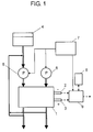
- Fig. 1 is a block diagram showing a configuration of a fuel cell system in accordance with an exemplary embodiment of the present invention.
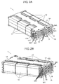
- Figs. 2A and 2B are perspective views showing a fuel cell stack in accordance with the exemplary embodiment of the present invention.
- Fig. 3 is an enlarged sectional view showing a fuel supplying side of the fuel cell stack shown in Fig. 2A .
- Fig. 4 is a plan view showing a surface facing an anode electrode, of a separator of the fuel cell stack.
- Fig. 5 is an enlarged sectional view showing an air supplying side of the fuel cell stack.
- Fig. 6 is a plan view showing a surface facing a cathode electrode, of the separator of the fuel cell stack.
- Fig. 7 is a conceptual sectional view showing a schematic configuration of a principal part of the fuel cell stack.
- the fuel cell system includes fuel cell stack 1, fuel tank 4, fuel pump 5, air pump 6, controller 7, storage section 8, and DC/DC converter 9.
- Fuel cell stack 1 has an electricity generation section. The generated electric power is output from anode terminal 3 of the negative electrode and cathode terminal 2 of the positive electrode. The output electric power is input into DC/DC converter 9.
- Fuel pump 5 supplies fuel in fuel tank 4 to anode electrode 31 of fuel cell stack 1.
- Air pump 6 supplies air as an oxidizing agent to cathode electrode 32 of fuel cell stack 1.
- Controller 7 controls the driving of fuel pump 5 and air pump 6, and controls DC/DC converter 9 so as to control the output to the outside and the charge and discharge to storage section 8.
- Fuel tank 4, fuel pump 5 and controller 7 constitute a fuel supply section that supplies fuel to anode electrode 31 in fuel cell stack 1.
- air pump 6 and controller 7 constitute a gas supply section that supplies a gas containing oxygen as an oxidizing agent to cathode electrode 32 in fuel cell stack 1.
- anode electrode 31 is supplied with a methanol aqueous solution as fuel, and cathode electrode 32 is supplied with air.
- the configurations of the fuel supply section and the gas supply section are not particularly limited to the above-mentioned configurations.
- fuel cell stack 1 includes cell stack 16, backing plates 14 and 15, first plate spring 11 and second plate spring 12.
- Cell stack 16 includes membrane electrode assemblies (MEAs) 35 as the electricity generation sections and separators 34 disposed so as to sandwich MEA 35 shown in Fig. 7 , and a pair of end plates 17 and 18.
- End plates 17 and 18 sandwich MEAs 35 and separators 34 from both sides in the laminating direction of MEAs 35, that is, from both sides in the laminating direction of MEAs 35 and separators 34.
- MEA 35 is formed by laminating anode electrode 31, cathode electrode 32, and electrolyte membrane 33 interposed between anode electrode 31 and cathode electrode 32.
- Anode electrode 31 includes diffusion layer 31A, microporous layer (MPL) 31B and catalyst layer 31C, which are laminated from the separator 34 side in this order.
- Cathode electrode 32 also includes diffusion layer 32A, microporous layer (MPL) 32B and catalyst layer 32C, which are laminated sequentially from the separator 34 side.
- Anode terminal 3 is electrically connected to anode electrode 31 and cathode terminal 2 is electrically connected to cathode electrode 32, respectively.
- Diffusion layers 31A and 32A are made of, for example, carbon paper, carbon felt, carbon cloth, and the like.
- MPLs 31B and 32B are made of, for example, polytetrafluoroethylene or a tetrafluoroethylene - hexafluoropropylene copolymer, and carbon.
- Catalyst layers 31C and 32C are formed by highly diffusing a catalyst such as platinum and ruthenium suitable for each electrode reaction onto a carbon surface and by binding those catalysts with a binder.
- Electrolyte membrane 33 is formed of an ion-exchange membrane which allows a hydrogen ion to permeate itself, for example, a perfluorosulfonic acid - tetrafluoroethylene copolymer.
- End plates 17 and 18 and separator 34 are made of a carbon material or stainless steel.
- fuel flow passage groove 34B for feeding fuel to anode electrode 31 is provided on the surface facing anode electrode 31 of separator 34.
- air flow passage groove 34D for feeding air to cathode electrode 32 is provided on the surface facing cathode electrode 32 of separator 34.
- plane portion (second plane portion) 34A is provided on the outer side with respect to MEA 35 on separator 34. That is to say, plane portion 34A is provided on a first side surface of cell stack 16, which is parallel to the laminating direction and is not fastened by first plate spring 11 and second plate spring 12. The dimension in the laminating direction of plane portion 34A is larger than the thickness of separator 34 in a portion where separators 34 sandwich MEA 35 or separator 34 and end plate 17 sandwich MEA 35.
- Plane portion 34A is provided with fuel inlet port (second fuel inlet port) 341 for taking in fuel from the outside. Through hole 34C is provided so as to communicate fuel inlet port 341 with fuel flow passage groove 34B.
- gas inlet port (second gas inlet port) 343 for taking in air from the outside is provided on the second side surface parallel to the laminating direction of cell stack 16.
- the second side surface faces the first side surface and is not fastened by first plate spring 11 and second plate spring 12.
- fuel outlet port (second fuel outlet port) 342 for exhausting at least any of reaction product of the fuel and reaction residue of the fuel as shown in Fig. 4 .
- gas inlet port 343 and fuel outlet port 342 are provided on the above-mentioned second side surface.
- fuel flow passage groove 17B is also provided on anode side end plate 17 facing anode electrode 31, and air flow passage groove 18D for feeding air is also provided at the cathode side end plate 18 facing cathode electrode 32.
- Fuel flow passage groove 17B is formed in the same shape as that of fuel flow passage groove 34B, and air flow passage groove 18D is formed in the same shape as that of air flow passage groove 34D.
- plane portion (first plane portion) 17A provided with fuel inlet port (first fuel inlet port) 171 is formed on end plate 17, and fuel flow passage groove 17B communicates with fuel inlet port 171 via through hole 17C.
- Gas inlet port (first gas inlet port) 181 for taking in air from the outside is provided on the second side surface parallel to the laminating direction of cell stack 16.
- Backing plate 14 is disposed at the anode electrode 31 side in cell stack 16, and backing plate 15 is disposed at the cathode electrode 32 side.
- Backing plates 14 and 15 are made of insulating resin, ceramic, resin containing a glass fiber, a metal plate coated with an electrically-insulating membrane, or the like.
- First plate spring 11 and second plate spring 12 tighten cell stack 16 with the spring elastic force thereof via backing plates 14 and 15.
- Second plate spring 12 is disposed so as to face first plate spring 11.
- First plate spring 11 and second plate spring 12 are made of, for example, a spring steel material.
- anode electrode 31 is supplied with an aqueous solution containing methanol by fuel pump 5.
- cathode electrode 32 is supplied with air compressed by air pump 6.
- a methanol aqueous solution as a fuel supplied to anode electrode 31, and methanol and water vapor derived from the methanol aqueous solution are diffused in diffusion layer 31A to the entire surface of MPL 31B. Then, they pass through MPL 31B and reach catalyst layer 31C.
- oxygen contained in the air supplied to cathode electrode 32 is diffused in diffusion layer 32A to the entire surface of MPL 32B.
- the oxygen further passes through MPL 32B and reaches catalyst layer 32C.
- Methanol that reaches catalyst layer 31C reacts as in formula (1)
- oxygen that reaches catalyst layer 32C reacts as in formula (2).
- cell stack 16 is fastened by first plate spring 11 and second plate spring 12 via backing plates 14 and 15.
- First plate spring 11 and second plate spring 12 fasten cell stack 16 extremely compactly along the outer shape of cell stack 16 as shown in Fig. 3 . That is to say, dead space is extremely small on the side surface of cell stack 16, and fuel cell stack 1 can be reduced in size as compared with a conventional case in which a cell stack is fastened by bolts and nuts.
- first plate spring 11 and second plate spring 12 have a pressing point in a relatively central portion in cell stack 16. Therefore, pressing power is operated in cell stack 16 uniformly in the planar direction of backing plates 14 and 15. With such a pressing power, entire cell stack 16 can be fastened uniformly. Thus, the electrochemical reactions expressed by the formulae (1) and (2) proceed uniformly in the planar direction of MEA 35. As a result, current-voltage characteristics offuel cell stack 1 are improved.
- Fig. 8 is a perspective view for illustrating the connection between fuel cell stack 1 and fuel pump 5.
- plane portions 17A and 34A are formed on the side surface to be connected to fuel pump 5.
- fuel discharging section (first fuel discharging section) 51A is provided on a position corresponding to plane portion 17A
- fuel discharging section (second fuel discharging section) 51B is provided on a position corresponding to plane portion 34A.
- seal member (first seal member) 52A is disposed on fuel discharging section 51A.
- seal member (second seal member) 52B is disposed. Seal members 52A and 52B are formed smaller in size than plane portions 17A and 34A, respectively.
- fuel inlet port 171 and fuel discharging section 51A are allowed to face each other, and fuel inlet port 341 and fuel discharging section 51B are allowed to face each other.
- fuel pump 5 and fuel cell stack 1 are fastened by, for example, a bolt so that seal members 52A and 52B are compressed by plane portions 17A and 34A. Thereby, a fuel passage is sealed.
- seal members 52A and 52B that are smaller in size than plane portions 17A and 34A, seal members 52A and 52B can connect fuel discharging sections 51A and 51B to fuel inlet ports 171 and 341 between seal members 52A and 52B and plane portions 17A and 34A without leakage.
- the fuel cell stack can be connected to fuel pump 5 with securely sealing by the use of plane portions 17A and 34A. This makes it possible to prevent fuel from leaking at the connection portion.
- plane portion 17A and plane portion 34A of separator 34 adjacent to end plate 17 are displaced from each other in the direction perpendicular to the laminating direction. Furthermore, when three or more MEAs 35 and two or more separators 34 are laminated, it is preferable that plane portions 34A are displaced from each other in the direction perpendicular to the laminating direction.
- plane portions 17A and 34A are provided at different positions from each other in laminating order. In such a position relation, plane portion 17A and plane portion 34A, or plane portions 34A are not brought into contact with each other. Therefore, it is possible to prevent short circuit in cell stack 16. Furthermore, the degree of freedom in disposing fuel discharging sections 51A and 51B is obtained.
- plane portion 17A and plane portion 34A or plane portions 34A are provided on the same plane.
- fuel discharging sections 51A and 51B may be provided on the same plane.
- fuel pump 5 is capable of individually controlling the flow rates of fuel discharged from fuel discharging sections 51A and 51B, respectively. By using such a fuel pump 5, it is possible to supply fuel at an optimum flow rate to each unit cell. In a unit cell, since there is a variation in the electromotive force and/or the pressure loss of flow passage, it is preferable that the flow rate of the fuel is controlled for each unit cell.
- Fig. 9 is a perspective view for illustrating the connection between fuel cell stack 1 and air pump 6.
- Fig. 10 is a front view showing a second side surface of fuel cell stack 1.
- Fig. 11 is a sectional view showing integrated member 61 to be attached to the second side surface.
- Air pump 6 constituting a gas supply section has gas discharging section 6A as shown in Fig. 11 and is attached to integrated member 61 by, for example, a screw as shown in Fig. 9 .
- Integrated member 61 includes gas discharging section 73, receiver section 74, and exhaust pipe 75.
- Gas discharging section 6A communicates with gas discharging section 73 of integrated member 61.
- Receiver section 74 is formed so that integrated member 61 receives exhaust from fuel outlet ports 172 and 342. Furthermore, receiver section 74 communicates with exhaust pipe 75. In this way, integrated member 61 is formed by integrating gas discharging section 73 and receiver section 74 receiving exhaust from fuel outlet ports 172 and 342.
- seal member (third seal member) 62 is attached to the second side surface provided with gas inlet ports 181 and 343 and fuel outlet ports 172 and 342 of cell stack 16 as shown in Figs. 9 and 10 .
- Seal member 62 has opening 63 in the position corresponding to gas inlet ports 181 and 343, and opening 64 in the position corresponding to fuel outlet ports 172 and 342.
- Integrated member 61 is attached to fuel cell stack 1 with seal member 62 sandwiched therebetween by screwing screws 65 into screw holes 67 provided on backing plates 14 and 15.
- seal member 62 separates gas inlet ports 181 and 343 from fuel outlet ports 172 and 342.
- seal member 62 connects gas discharging section 73 with gas inlet ports 181 and 343. Therefore, air sent from air pump 6 is supplied to gas inlet ports 181 and 343.
- seal member 62 connects receiver section 74 with fuel outlet ports 172 and 342.
- Fuel inlet ports 171 and 341 and gas inlet ports 181 and 343 may be formed on the same side surface.
- fuel inlet ports 171 and 341 and gas inlet ports 181 and 343 can be provided on one surface. Also in this case, when plane portions 17A and 34A are provided, fuel can be prevented from leaking.
- first plate spring 11 is arranged so as to press the vicinity of the center part of end plates 17 and 18.
- second plate spring 12 may further be used.
- first plate springs 11 and second plate springs 12 are used.
- one first plate spring 11 and one second plate spring 12 may be used depending upon the size of cell stack 16.
- the subject to be pressed may be a single cell or a cell stack.
- One plate spring may be used and a plurality of or a pair of or a plural pairs of plate springs may be used.
- end plates 17 and 18 may be directly sandwiched by first plate spring 11 (and second plate spring 12).
- an insulating film is formed inside the C-shaped cross section of first plate spring 11 (and second plate spring 12) so that first plate spring 11 does not cause short circuit.
- fastening section for example, screw hole 67
- to fuel pump 5 and integrated member 61 are provided on end plates 17 and 18. That is to say, backing plates 14 and 15 are not essential.
- backing plates 14 and 15 are provided and that backing plates 14 and 15 are formed of different materials from those of end plates 17 and 18.
- backing plates 14 and 15 are formed of different materials from those of end plates 17 and 18.
- cell stack 16 is fastened by using first plate spring 11 and second plate spring 12, and fuel and air are supplied from the side surfaces that are opposite each other and are not fastened by first plate spring 11 and second plate spring 12.
- first plate spring 11 and second plate spring 12 a side surface, which is covered with second plate spring 12 in this exemplary embodiment, may be used for supplying fuel and air.
- a pair of backing plates are fastened by, for example, a bolt, without using first plate spring 11 and second plate spring 12, any side surfaces may be used for supplying fuel and air.
- DMFC is described as an example.
- the configuration of the present invention can be applied to any fuel cells using a power generation element that is the same as cell stack 16.
- a power generation element that is the same as cell stack 16.
- it may be applied to a so-called polymer solid electrolyte fuel cell and a methanol modified fuel cell, which use hydrogen as fuel.
- a fuel cell stack of the present invention is provided with plane portions on end plates and separators and these plane portions are disposed on the stack side surface. Furthermore, a fuel inlet port is provided on each of the plane portions. Then, in a fuel cell system of the present invention, a fuel discharging section of a fuel pump and a fuel inlet port are connected water-tightly to each other by using the plane portions. Thus, fuel can be prevented from leaking.
- a fuel cell stack and the fuel cell system using the fuel cell stack are particularly useful as a power source of small electronic devices.
Landscapes
- Life Sciences & Earth Sciences (AREA)
- Engineering & Computer Science (AREA)
- Manufacturing & Machinery (AREA)
- Sustainable Development (AREA)
- Sustainable Energy (AREA)
- Chemical & Material Sciences (AREA)
- Chemical Kinetics & Catalysis (AREA)
- Electrochemistry (AREA)
- General Chemical & Material Sciences (AREA)
- Fuel Cell (AREA)
Abstract
Description
- The present invention relates to a fuel cell stack and a fuel cell system using the same. More particularly, it relates to a structure for supplying fuel and an oxidizing agent to a fuel cell stack.
- Recently, with the rapid widespread of portable and cordless electronic devices, as driving power sources for such devices, small, lightweight and large energy density secondary batteries have been increasingly demanded. Furthermore, technology development has been accelerated in not only secondary batteries used for small consumer goods but also large secondary batteries for electric power storages and electric vehicles, which require long-time durability and safety. Furthermore, much attention has been paid to fuel cells enabling long-time continuous use with fuel supplied, rather than secondary batteries that need charging.
- A fuel cell system includes a fuel cell stack including a cell stack, a fuel supply section for supplying fuel to the cell stack, and an oxidizing agent supply section for supplying an oxidizing agent to the cell stack. The cell stack is formed by laminating a membrane electrode assembly that includes an anode electrode, a cathode electrode, and an electrolyte membrane interposed between the anode and cathode electrodes, and a separator onto each other, and disposing end plates on the both end sides in the laminating direction.
- In general, end plates and separators have holes penetrating in the thickness direction. When a cell stack is formed, the holes coincide with each other to form flow passages for fuel and an oxidizing agent. Then, the flow passages are connected to a fuel supply port and an oxidizing agent supply port provided on backing plates disposed outside the end plates (for example, Patent Document 1).
- However, in this structure, in order to form flow passages for fuel and an oxidizing agent, it is necessary to laminate the end plates, the separators and the backing plates precisely. Furthermore, since it is necessary to increase the size of the end plate and separator by the size of the flow passage, the size of the cell stack is increased.
- Meanwhile, a fuel cell stack, in which fuel and an oxidizing agent are supplied from a side surface parallel to the laminating direction, is proposed (for example, Patent Document 2). This fuel cell stack is formed by combining two unit cells to form a module and electrically connecting the modules. In each unit cell, a fuel supply port is provided on the side surface of the end plate at the anode side, and a through hole penetrating from the fuel supply port to a flow passage groove formed on the surface facing the anode electrode is provided. Thus, fuel can be supplied from the side surface parallel to the laminating direction, thus reducing the size of the fuel cell stack in the planer direction.
- However,
Patent Document 2 does not disclose a seal structure of a connection portion between a fuel supply port and a device such as a pump for supplying fuel to the fuel cell stack in detail. Since fuel such as methanol has toxicity, tight sealing is required. However, when the end plate is made to be thin, the size of the fuel supply port is also reduced. Therefore, it is difficult to carry out connection while a fuel leakage is prevented. - Furthermore, according to
Patent Document 2, fuel supply ports of unit cells in the module are joined into one port, to which a fuel is supplied uniformly. However, in cells, there is variation in electromotive force or a pressure loss of the flow passage, it is preferable that a flow rate is controlled for every unit cell. On the contrary, it is not possible to control the fuel flow rate for every unit cell in the above-mentioned fuel supply method. -
- Patent Document 1: Japanese Patent Unexamined Publication No.
2005-317310 - Patent Document 2: Japanese Patent Unexamined Publication No.
2006-351525 - The present invention provides a fuel cell stack having a structure capable of being connected to a fuel pump reliably even in the case where a thin end plate and a separator are used and fuel is supplied from the side surface parallel to the laminating direction.
- The fuel cell stack of the present invention includes a membrane electrode assembly, and a pair of end plates. The membrane electrode assembly and the end plates constitute a unit cell of fuel cell. The membrane electrode assembly is formed by laminating an anode electrode, a cathode electrode, and an electrolyte membrane interposed between the anode and cathode electrodes. The end plates are disposed so as to sandwich the membrane electrode assembly from both sides in the laminating direction of the membrane electrode assembly. The fuel cell stack has a first side surface and a second side surface which are parallel to the laminating direction. An anode side end plate has a first plane portion on the first side surface. The dimension in the laminating direction of the first plane portion is made to be larger than a thickness of the anode side end plate in a portion where the membrane electrode assembly is sandwiched. The first plane portion is provided with a first fuel inlet port for taking in fuel from the outside. The cathode side end plate has a first gas inlet port on the second side surface. The first gas inlet port is configured to take in a gas containing an oxidizing agent from the outside
- In this fuel cell stack, the first fuel inlet port is provided on the first plane portion. Thereby, even in the case where thin end plates are used, the fuel cell stack can be connected to the fuel supply section (fuel pump) by carrying out reliable sealing with the use of the first plane portion. Thus, it is possible to prevent fuel from leaking. In this way, it is possible to secure the sealing in a connection portion that supplies fuel from the fuel supply section to the fuel cell stack.
-
-
Fig. 1 is a block diagram showing a configuration of a fuel cell system in accordance with an exemplary embodiment of the present invention. -
Fig. 2A is a perspective view showing a fuel cell stack in accordance with the exemplary embodiment of the present invention. -
Fig. 2B is a perspective view showing an opposite side of the fuel cell stack ofFig. 2A in accordance with the exemplary embodiment of the present invention. -
Fig. 3 is an enlarged sectional view showing a fuel supplying side of the fuel cell stack shown inFig. 2A . -
Fig. 4 is a plan view showing a surface facing an anode electrode, of a separator of the fuel cell stack shown inFig. 2A . -
Fig. 5 is an enlarged sectional view showing an air supplying side of the fuel cell stack shown inFig. 2B . -
Fig. 6 is a plan view showing a surface facing a cathode electrode, of the separator of the fuel cell stack shown inFig. 2B . -
Fig. 7 is a conceptual sectional view showing a schematic configuration of a principal part of the fuel cell stack shown inFig. 2A . -
Fig. 8 is a perspective view for illustrating a connection between the fuel cell stack shown inFig. 2B and a fuel pump shown inFig. 1 . -
Fig. 9 is a perspective view for illustrating a connection between the fuel cell stack shown inFig. 2B and an air pump shown inFig. 1 . -
Fig. 10 is a front view showing a second side surface of the fuel cell stack shown inFig. 2B . -
Fig. 11 is a sectional view showing an integrated member attached to the second side surface of the fuel cell stack shown inFig. 2B . - Hereinafter, an exemplary embodiment of the present invention is described with reference to drawings in which a direct methanol fuel cell (DMFC) is taken as an example. Note here that the present invention is not limited to the embodiment mentioned below as long as it is based on the basic features described in the description.
-
Fig. 1 is a block diagram showing a configuration of a fuel cell system in accordance with an exemplary embodiment of the present invention.Figs. 2A and 2B are perspective views showing a fuel cell stack in accordance with the exemplary embodiment of the present invention.Fig. 3 is an enlarged sectional view showing a fuel supplying side of the fuel cell stack shown inFig. 2A .Fig. 4 is a plan view showing a surface facing an anode electrode, of a separator of the fuel cell stack.Fig. 5 is an enlarged sectional view showing an air supplying side of the fuel cell stack.Fig. 6 is a plan view showing a surface facing a cathode electrode, of the separator of the fuel cell stack.Fig. 7 is a conceptual sectional view showing a schematic configuration of a principal part of the fuel cell stack. - The fuel cell system includes
fuel cell stack 1,fuel tank 4,fuel pump 5,air pump 6,controller 7,storage section 8, and DC/DC converter 9.Fuel cell stack 1 has an electricity generation section. The generated electric power is output fromanode terminal 3 of the negative electrode andcathode terminal 2 of the positive electrode. The output electric power is input into DC/DC converter 9.Fuel pump 5 supplies fuel infuel tank 4 toanode electrode 31 offuel cell stack 1.Air pump 6 supplies air as an oxidizing agent tocathode electrode 32 offuel cell stack 1.Controller 7 controls the driving offuel pump 5 andair pump 6, and controls DC/DC converter 9 so as to control the output to the outside and the charge and discharge tostorage section 8.Fuel tank 4,fuel pump 5 andcontroller 7 constitute a fuel supply section that supplies fuel toanode electrode 31 infuel cell stack 1. On the other hand,air pump 6 andcontroller 7 constitute a gas supply section that supplies a gas containing oxygen as an oxidizing agent tocathode electrode 32 infuel cell stack 1. - As shown in
Fig. 7 ,anode electrode 31 is supplied with a methanol aqueous solution as fuel, andcathode electrode 32 is supplied with air. Note here that the configurations of the fuel supply section and the gas supply section are not particularly limited to the above-mentioned configurations. - As shown in
Fig. 2A ,fuel cell stack 1 includescell stack 16,backing plates first plate spring 11 andsecond plate spring 12.Cell stack 16 includes membrane electrode assemblies (MEAs) 35 as the electricity generation sections andseparators 34 disposed so as tosandwich MEA 35 shown inFig. 7 , and a pair ofend plates End plates sandwich MEAs 35 andseparators 34 from both sides in the laminating direction ofMEAs 35, that is, from both sides in the laminating direction ofMEAs 35 andseparators 34. As shown inFig. 7 ,MEA 35 is formed by laminatinganode electrode 31,cathode electrode 32, andelectrolyte membrane 33 interposed betweenanode electrode 31 andcathode electrode 32. -
Anode electrode 31 includesdiffusion layer 31A, microporous layer (MPL) 31B andcatalyst layer 31C, which are laminated from theseparator 34 side in this order.Cathode electrode 32 also includesdiffusion layer 32A, microporous layer (MPL) 32B andcatalyst layer 32C, which are laminated sequentially from theseparator 34 side.Anode terminal 3 is electrically connected toanode electrode 31 andcathode terminal 2 is electrically connected tocathode electrode 32, respectively. Diffusion layers 31A and 32A are made of, for example, carbon paper, carbon felt, carbon cloth, and the like.MPLs Electrolyte membrane 33 is formed of an ion-exchange membrane which allows a hydrogen ion to permeate itself, for example, a perfluorosulfonic acid - tetrafluoroethylene copolymer. -
End plates separator 34 are made of a carbon material or stainless steel. As shown inFigs. 3, 4 , and7 , fuelflow passage groove 34B for feeding fuel toanode electrode 31 is provided on the surface facinganode electrode 31 ofseparator 34. On the other hand, as shown inFigs. 5, 6 , and7 , airflow passage groove 34D for feeding air tocathode electrode 32 is provided on the surface facingcathode electrode 32 ofseparator 34. - As shown in
Fig. 3 , on the outer side with respect toMEA 35 onseparator 34, plane portion (second plane portion) 34A is provided. That is to say,plane portion 34A is provided on a first side surface ofcell stack 16, which is parallel to the laminating direction and is not fastened byfirst plate spring 11 andsecond plate spring 12. The dimension in the laminating direction ofplane portion 34A is larger than the thickness ofseparator 34 in a portion whereseparators 34sandwich MEA 35 orseparator 34 andend plate 17sandwich MEA 35.Plane portion 34A is provided with fuel inlet port (second fuel inlet port) 341 for taking in fuel from the outside. Throughhole 34C is provided so as to communicatefuel inlet port 341 with fuelflow passage groove 34B. On the other hand, as shown inFig. 5 , on the second side surface parallel to the laminating direction ofcell stack 16, gas inlet port (second gas inlet port) 343 for taking in air from the outside is provided. The second side surface faces the first side surface and is not fastened byfirst plate spring 11 andsecond plate spring 12. - Note here that the opposite side to fuel
inlet port 341 of fuelflow passage groove 34B communicates with fuel outlet port (second fuel outlet port) 342 for exhausting at least any of reaction product of the fuel and reaction residue of the fuel as shown inFig. 4 . As mentioned below,gas inlet port 343 andfuel outlet port 342 are provided on the above-mentioned second side surface. - Note here that fuel
flow passage groove 17B is also provided on anodeside end plate 17 facinganode electrode 31, and airflow passage groove 18D for feeding air is also provided at the cathodeside end plate 18 facingcathode electrode 32. Fuelflow passage groove 17B is formed in the same shape as that of fuelflow passage groove 34B, and airflow passage groove 18D is formed in the same shape as that of airflow passage groove 34D. Furthermore, plane portion (first plane portion) 17A provided with fuel inlet port (first fuel inlet port) 171 is formed onend plate 17, and fuelflow passage groove 17B communicates withfuel inlet port 171 via throughhole 17C. Gas inlet port (first gas inlet port) 181 for taking in air from the outside is provided on the second side surface parallel to the laminating direction ofcell stack 16. - Backing
plate 14 is disposed at theanode electrode 31 side incell stack 16, andbacking plate 15 is disposed at thecathode electrode 32 side. Backingplates -
First plate spring 11 andsecond plate spring 12 tightencell stack 16 with the spring elastic force thereof viabacking plates Second plate spring 12 is disposed so as to facefirst plate spring 11.First plate spring 11 andsecond plate spring 12 are made of, for example, a spring steel material. - Next, an operation in
fuel cell stack 1 is briefly described. As shown inFigs. 1 and7 ,anode electrode 31 is supplied with an aqueous solution containing methanol byfuel pump 5. On the other hand,cathode electrode 32 is supplied with air compressed byair pump 6. A methanol aqueous solution as a fuel supplied toanode electrode 31, and methanol and water vapor derived from the methanol aqueous solution are diffused indiffusion layer 31A to the entire surface ofMPL 31B. Then, they pass throughMPL 31B and reachcatalyst layer 31C. - On the other hand, oxygen contained in the air supplied to
cathode electrode 32 is diffused indiffusion layer 32A to the entire surface ofMPL 32B. The oxygen further passes throughMPL 32B and reachescatalyst layer 32C. Methanol that reachescatalyst layer 31C reacts as in formula (1), and oxygen that reachescatalyst layer 32C reacts as in formula (2).
CH3OH + H2O→ CO2 + 6H+ + 6e- (1)
3/2O2 + 6H+ + 6e- → 3H2O (2)
- As a result, electric power is generated, as well as carbon dioxide is generated at the
anode electrode 31 side and water is generated at thecathode electrode 32 side as reaction products, respectively. Carbon dioxide is exhausted to the outside offuel cell stack 1. Gases such as nitrogen that do not react incathode electrode 32 and unreacted oxygen are also exhausted to the outside offuel cell stack 1. Note here that since not all methanol in the aqueous solution react at theanode electrode 31 side, the exhausted aqueous solution is generally allowed to return tofuel pump 5 as shown inFig. 1 . Furthermore, since water is consumed in the reaction inanode electrode 31, water generated incathode electrode 32 may be allowed to return to theanode electrode 31 side as shown inFig. 1 . - In the exemplary embodiment,
cell stack 16 is fastened byfirst plate spring 11 andsecond plate spring 12 viabacking plates First plate spring 11 andsecond plate spring 12 fastencell stack 16 extremely compactly along the outer shape ofcell stack 16 as shown inFig. 3 . That is to say, dead space is extremely small on the side surface ofcell stack 16, andfuel cell stack 1 can be reduced in size as compared with a conventional case in which a cell stack is fastened by bolts and nuts. - Furthermore, in a case in which a cell stack is fastened by using bolts and nuts, a pressing point is provided at the outside (in the vicinity of the outer periphery) of
cell stack 16. However,first plate spring 11 andsecond plate spring 12 have a pressing point in a relatively central portion incell stack 16. Therefore, pressing power is operated incell stack 16 uniformly in the planar direction ofbacking plates entire cell stack 16 can be fastened uniformly. Thus, the electrochemical reactions expressed by the formulae (1) and (2) proceed uniformly in the planar direction ofMEA 35. As a result, current-voltage characteristics offuelcell stack 1 are improved. - Next, the connection between
fuel cell stack 1 andfuel pump 5 is described with reference toFigs. 2A and8. Fig. 8 is a perspective view for illustrating the connection betweenfuel cell stack 1 andfuel pump 5. - As shown in
Fig. 2A ,plane portions fuel pump 5. Infuel pump 5, fuel discharging section (first fuel discharging section) 51A is provided on a position corresponding to planeportion 17A, and fuel discharging section (second fuel discharging section) 51B is provided on a position corresponding to planeportion 34A. Onfuel discharging section 51A, seal member (first seal member) 52A is disposed. Similarly, onfuel discharging section 51B, seal member (second seal member) 52B is disposed.Seal members plane portions fuel inlet port 171 andfuel discharging section 51A are allowed to face each other, andfuel inlet port 341 andfuel discharging section 51B are allowed to face each other. Furthermore,fuel pump 5 andfuel cell stack 1 are fastened by, for example, a bolt so thatseal members plane portions seal members plane portions seal members fuel discharging sections inlet ports seal members plane portions - With this structure, even if
thin end plate 17 andseparator 34 are used, the fuel cell stack can be connected tofuel pump 5 with securely sealing by the use ofplane portions - Note here that as shown in
Fig. 2A , it is preferable thatplane portion 17A andplane portion 34A ofseparator 34 adjacent to endplate 17 are displaced from each other in the direction perpendicular to the laminating direction. Furthermore, when three or more MEAs 35 and two ormore separators 34 are laminated, it is preferable thatplane portions 34A are displaced from each other in the direction perpendicular to the laminating direction. - In
Fig. 2A ,plane portions plane portion 17A andplane portion 34A, orplane portions 34A are not brought into contact with each other. Therefore, it is possible to prevent short circuit incell stack 16. Furthermore, the degree of freedom in disposingfuel discharging sections - Furthermore, it is further preferable that
plane portion 17A andplane portion 34A orplane portions 34A are provided on the same plane. By providingplane portion 17A andplane portion 34A on the same plane in which they are displaced from each other in the direction perpendicular to the laminating direction,fuel discharging sections fuel pump 5, whenfuel discharging sections plane portions - Furthermore, it is preferable that
fuel pump 5 is capable of individually controlling the flow rates of fuel discharged fromfuel discharging sections fuel pump 5, it is possible to supply fuel at an optimum flow rate to each unit cell. In a unit cell, since there is a variation in the electromotive force and/or the pressure loss of flow passage, it is preferable that the flow rate of the fuel is controlled for each unit cell. - Next, the connection between
fuel cell stack 1 andair pump 6 is described with reference toFigs. 2B and9 through 11 .Fig. 9 is a perspective view for illustrating the connection betweenfuel cell stack 1 andair pump 6.Fig. 10 is a front view showing a second side surface offuel cell stack 1.Fig. 11 is a sectional view showingintegrated member 61 to be attached to the second side surface. -
Air pump 6 constituting a gas supply section hasgas discharging section 6A as shown inFig. 11 and is attached tointegrated member 61 by, for example, a screw as shown inFig. 9 . Integratedmember 61 includesgas discharging section 73,receiver section 74, andexhaust pipe 75.Gas discharging section 6A communicates withgas discharging section 73 ofintegrated member 61.Receiver section 74 is formed so thatintegrated member 61 receives exhaust fromfuel outlet ports receiver section 74 communicates withexhaust pipe 75. In this way, integratedmember 61 is formed by integratinggas discharging section 73 andreceiver section 74 receiving exhaust fromfuel outlet ports - On the other hand, seal member (third seal member) 62 is attached to the second side surface provided with
gas inlet ports fuel outlet ports cell stack 16 as shown inFigs. 9 and 10 .Seal member 62 hasopening 63 in the position corresponding togas inlet ports outlet ports - Integrated
member 61 is attached tofuel cell stack 1 withseal member 62 sandwiched therebetween by screwingscrews 65 into screw holes 67 provided onbacking plates seal member 62 separatesgas inlet ports fuel outlet ports seal member 62 connectsgas discharging section 73 withgas inlet ports air pump 6 is supplied togas inlet ports seal member 62 connectsreceiver section 74 withfuel outlet ports - By using integrated
member 61 andseal member 62 in this way, an air introducing passage and a fuel side exhaust passage can be formed in compact in size on the second side surface. As a result, a fuel cell system can be miniaturized. - In the above description, a configuration in which
fuel inlet ports fuel cell stack 1 andgas inlet ports Fuel inlet ports gas inlet ports fuel inlet ports gas inlet ports plane portions - Furthermore, a configuration is described in which a plurality of
MEAs 35 are laminated withseparator 34 disposed betweenMEAs 35,end plates cell stack 16, andbacking plates outside end plates single MEA 35 may be sandwiched byend plates MEA 35 andend plates first plate spring 11. In this case, it is preferable thatfirst plate spring 11 is arranged so as to press the vicinity of the center part ofend plates second plate spring 12 may further be used. Furthermore, inFig. 2A , a plurality of first plate springs 11 and second plate springs 12 are used. However, onefirst plate spring 11 and onesecond plate spring 12 may be used depending upon the size ofcell stack 16. Thus, the subject to be pressed may be a single cell or a cell stack. One plate spring may be used and a plurality of or a pair of or a plural pairs of plate springs may be used. - Furthermore, without using
backing plates end plates first plate spring 11 does not cause short circuit. Furthermore, fastening section (for example, screw hole 67) tofuel pump 5 andintegrated member 61 are provided onend plates backing plates - However, it is preferable that
backing plates backing plates end plates backing plates first plate spring 11 andend plates backing plates end plates backing plates first plate spring 11. As a result, a unit cell of fuel cell or a cell stack can be fastened more uniformly in the planner direction ofMEA 35. Furthermore, since backingplates first plate spring 11. - Note here that in this exemplary embodiment,
cell stack 16 is fastened by usingfirst plate spring 11 andsecond plate spring 12, and fuel and air are supplied from the side surfaces that are opposite each other and are not fastened byfirst plate spring 11 andsecond plate spring 12. However, the present invention is not limited to this configuration. Whensecond plate spring 12 is not used, a side surface, which is covered withsecond plate spring 12 in this exemplary embodiment, may be used for supplying fuel and air. Furthermore, when a pair of backing plates are fastened by, for example, a bolt, without usingfirst plate spring 11 andsecond plate spring 12, any side surfaces may be used for supplying fuel and air. - In the exemplary embodiment, DMFC is described as an example. However, the configuration of the present invention can be applied to any fuel cells using a power generation element that is the same as
cell stack 16. For example, it may be applied to a so-called polymer solid electrolyte fuel cell and a methanol modified fuel cell, which use hydrogen as fuel. - A fuel cell stack of the present invention is provided with plane portions on end plates and separators and these plane portions are disposed on the stack side surface. Furthermore, a fuel inlet port is provided on each of the plane portions. Then, in a fuel cell system of the present invention, a fuel discharging section of a fuel pump and a fuel inlet port are connected water-tightly to each other by using the plane portions. Thus, fuel can be prevented from leaking. Such a fuel cell stack and the fuel cell system using the fuel cell stack are particularly useful as a power source of small electronic devices.
-
- 1
- fuel cell stack
- 2
- cathode terminal
- 3
- anode terminal
- 4
- fuel tank
- 5
- fuel pump
- 6
- air pump
- 6A, 73
- gas discharging section
- 7
- controller
- 8
- storage section
- 9
- DC/DC converter
- 11
- first plate spring
- 12
- second plate spring
- 14, 15
- backing plate
- 16
- cell stack
- 17, 18
- end plate
- 17A
- plane portion (first plane portion)
- 17B, 34B
- fuel flow passage groove
- 17C, 34C
- through hole
- 18D, 34D
- air flow passage groove
- 31
- anode electrode
- 31A, 32A
- diffusion layer
- 31B, 32B
- microporous layer (MPL)
- 31C, 32C
- catalyst layer
- 32
- cathode electrode
- 33
- electrolyte film
- 34
- separator
- 34A
- plane portion (second plane portion)
- 35
- membrane electrode assembly (MEA)
- 51A
- fuel discharging section (first fuel discharging section)
- 51B
- fuel discharging section (second fuel discharging section)
- 52A
- seal member (first seal member)
- 52B
- seal member (second seal member)
- 61
- integrated member
- 62
- seal member (third seal member)
- 63, 64
- opening
- 65
- screw
- 67
- screw hole
- 74
- receiver section
- 75
- exhaust pipe
- 171
- fuel inlet port (first fuel inlet port)
- 172
- fuel outlet port (first fuel outlet port)
- 181
- gas inlet port (first gas inlet port)
- 341
- fuel inlet port (second fuel inlet port)
- 342
- fuel outlet port (second fuel outlet port)
- 343
- gas inlet port (second gas inlet port)
Claims (13)
- A fuel cell stack comprising:a membrane electrode assembly formed by laminating an anode electrode, a cathode electrode, an electrolyte membrane interposed between the anode electrode and the cathode electrode onto each other; andan anode side end plate and a cathode side end plate sandwiching the membrane electrode assembly from both sides in a laminating direction of the membrane electrode assembly,wherein the fuel cell stack has a first side surface parallel to the laminating direction,the anode side end plate has a first plane portion on the first side surface, the first plane portion is formed larger in the laminating direction than a thickness of a portion in which the anode side end plate sandwiches the membrane electrode assembly, andthe first plane portion is provided with a first fuel inlet port for taking in fuel from outside.
- The fuel cell stack according to claim 1,
wherein the fuel cell stack further comprises a second side surface that is different from the first side surface and is provided in parallel to the laminating direction, and
the cathode side end plate has a first gas inlet port configured to take in a gas containing an oxidizing agent from outside, on the second side surface. - The fuel cell stack according to claim 2,
wherein the membrane electrode assembly is one of membrane electrode assemblies, the fuel cell stack comprises the membrane electrode assemblies, and a separator is provided between each two of the membrane electrode assemblies to form a cell stack, and
the separator has a second gas inlet port configured to take in the gas from outside on the second side surface so as to correspond to the cathode electrode of each of the membrane electrode assemblies. - The fuel cell stack according to claim 1,
wherein the membrane electrode assembly is one of membrane electrode assemblies, the fuel cell stack comprises the membrane electrode assemblies, and a separator is provided between each two of the membrane electrode assemblies to form a cell stack, and
the separator has a second plane portion formed larger in the laminating direction than a thickness of a portion in which the separator is sandwiched by the membrane electrode assemblies on the first side surface so as to correspond to the anode electrode of each of the membrane electrode assemblies, and
the second plane portion is provided with a second fuel inlet port configured to take in the fuel from outside. - The fuel cell stack according to claim 4,
wherein the first plane portion and the second plane portion of the separator adjacent to the end plate are provided such that they are displaced from each other in a direction perpendicular to the laminating direction. - The fuel cell stack according to claim 5,
wherein the first plane portion and the second plane portion are provided on a same plane. - The fuel cell stack according to claim 4,
wherein the membrane electrode assembly is one of three or more membrane electrode assemblies, the fuel cell stack comprises the three or more membrane electrode assemblies,
the separator is one of two or more separators, the fuel cell stack comprises the two or more separators, and
the second plane portions are provided such that they are displaced from each other in the direction perpendicular to the laminating direction. - The fuel cell stack according to claim 7,
wherein the first plane portion and the second plane portions are provided on a same plane. - A fuel cell system comprising:the fuel cell stack according to claim 1; anda fuel supply section having a first fuel discharging section in a position corresponding to the first plane portion and being configured to supply the fuel to the first fuel inlet port,wherein the fuel supply section has a first seal member smaller than the first plane portion at the first fuel discharging section.
- The fuel cell system according to claim 9,
wherein the membrane electrode assembly is one of membrane electrode assemblies, the fuel cell stack comprises the membrane electrode assemblies, and a separator is provided between each two of the membrane electrode assemblies to form a cell stack,
the separator has a second plane portion formed larger in the laminating direction than a thickness of a portion in which the separator is sandwiched by the membrane electrode assemblies on the first side surface so as to correspond to the anode electrode of each of the membrane electrode assemblies, and the second plane portion is provided with a second fuel inlet port configured to take in the fuel from outside,
the fuel supply section further comprises a second fuel discharging section in a position corresponding to the second plane portion and is configured to supply the fuel to the first fuel inlet port and the second fuel inlet port, and
the fuel supply section further comprises a second seal member that is smaller than the second plane portion in the second fuel discharging section. - The fuel cell system according to claim 9,
wherein the membrane electrode assembly is one of membrane electrode assemblies, the fuel cell stack comprises the membrane electrode assemblies, and a separator is provided between each two of the membrane electrode assemblies to form a cell stack,
the separator has a second plane portion formed larger in the laminating direction than a thickness of a portion in which the separator is sandwiched by the membrane electrode assemblies on the first side surface so as to correspond to the anode electrode of each of the membrane electrode assemblies, and the second plane portion is provided with a second fuel inlet port configured to take in the fuel from outside,
the fuel supply section further comprises a second fuel discharging section in a position corresponding to the second plane portion and is configured to supply the fuel to the first fuel inlet port and the second fuel inlet port, and
the fuel supply section is capable of separately controlling a flow rate of the fuel discharged respectively from the first fuel discharging section and the second fuel discharging section. - A fuel cell system comprising:the fuel cell stack according to claim 1;a fuel supply section configured to supply the fuel to the first fuel inlet port, anda gas supply section having a gas discharging section, the gas supply section being configured to supply the gas to the first gas inlet port,wherein the fuel cell stack further comprises a second side surface that is different from the first side surface and is provided in parallel to the laminating direction,
the cathode side end plate has a first gas inlet port configured to take in a gas containing an oxidizing agent from outside, on the second side surface,the anode side end plate has a first fuel outlet port configured to exhaust at least any of a reaction product of the fuel or a reaction residue of the fuel, on the second side surface,the fuel cell system further comprises:an integrated member formed by integrating the gas discharging section of the gas supply section and a receiver section configured to receive exhaust from the first fuel outlet port, anda third seal member separating the first gas inlet port from the first fuel outlet port, connecting the gas discharging section to the first gas inlet port, and connecting the receiver section to the first fuel outlet port. - The fuel cell system according to claim 12,
wherein the membrane electrode assembly is one of membrane electrode assemblies, the fuel cell stack comprises the membrane electrode assemblies, and a separator is provided between each two of the membrane electrode assemblies to form a cell stack,
the separator has a second plane portion formed larger in the laminating direction than a thickness of a portion in which the separator is sandwiched by the membrane electrode assemblies on the first side surface so as to correspond to the anode electrode of each of the membrane electrode assemblies,
the second plane portion is provided with a second fuel inlet port configured to take in the fuel from outside,
the separator has a second gas inlet port configured to take in the gas from outside on the second side surface so as to correspond to the cathode electrode of each of the membrane electrode assemblies,
the fuel supply section is configured to supply the fuel to the first fuel inlet port and the second fuel inlet port,
the gas supply section is configured to supply the gas to the first gas inlet port and the second gas inlet port,
the separator has a second fuel outlet port configured to exhaust at least any of a reaction product of the fuel and a reaction residue of the fuel on the second side surface,
the integrated member is formed by integrating the gas discharging section of the gas supply section and a receiver section configured to receive exhaust from the first and second fuel outlet ports,
the third seal member is configured to separate the first and second gas inlet ports from the first and second fuel outlet ports, connect the gas discharging section to the first and second gas inlet ports, and connect the receiver section to the first and second fuel outlet ports.
Applications Claiming Priority (2)
| Application Number | Priority Date | Filing Date | Title |
|---|---|---|---|
| JP2008203982 | 2008-08-07 | ||
| PCT/JP2009/003735 WO2010016247A1 (en) | 2008-08-07 | 2009-08-05 | Fuel cell stack and fuel cell system employing the same |
Publications (1)
| Publication Number | Publication Date |
|---|---|
| EP2323209A1 true EP2323209A1 (en) | 2011-05-18 |
Family
ID=41663475
Family Applications (1)
| Application Number | Title | Priority Date | Filing Date |
|---|---|---|---|
| EP09804734A Withdrawn EP2323209A1 (en) | 2008-08-07 | 2009-08-05 | Fuel cell stack and fuel cell system employing the same |
Country Status (5)
| Country | Link |
|---|---|
| US (1) | US20110177418A1 (en) |
| EP (1) | EP2323209A1 (en) |
| JP (1) | JP5077358B2 (en) |
| CN (1) | CN101816091A (en) |
| WO (1) | WO2010016247A1 (en) |
Families Citing this family (5)
| Publication number | Priority date | Publication date | Assignee | Title |
|---|---|---|---|---|
| GB2501700A (en) * | 2012-05-01 | 2013-11-06 | Intelligent Energy Ltd | Fuel cell stack assembly |
| US10293456B2 (en) * | 2017-04-19 | 2019-05-21 | Rohm And Haas Electronic Materials Cmp Holdings, Inc. | Aliphatic polyurethane optical endpoint detection windows and CMP polishing pads containing them |
| JP6518821B1 (en) * | 2018-06-06 | 2019-05-22 | 日本碍子株式会社 | Cell stack device |
| JP2020007634A (en) * | 2018-07-03 | 2020-01-16 | パナソニックIpマネジメント株式会社 | Electrochemical hydrogen pump |
| KR20220015724A (en) * | 2020-07-31 | 2022-02-08 | 현대자동차주식회사 | Fuel cell |
Family Cites Families (9)
| Publication number | Priority date | Publication date | Assignee | Title |
|---|---|---|---|---|
| JPS60862U (en) * | 1983-06-16 | 1985-01-07 | 株式会社 富士電機総合研究所 | Fuel cell |
| JPS6188464A (en) * | 1984-10-05 | 1986-05-06 | Hitachi Ltd | Fuel cell |
| JPS62232868A (en) * | 1986-04-02 | 1987-10-13 | Mitsubishi Electric Corp | Gas distributor |
| JPH0582152A (en) * | 1991-09-20 | 1993-04-02 | Fuji Electric Co Ltd | Manifold installation structure of fuel cell |
| EP0981175B1 (en) * | 1998-08-20 | 2012-05-02 | Panasonic Corporation | Polymer electrolyte fuel cell stack |
| JP3925172B2 (en) * | 2000-12-28 | 2007-06-06 | 三菱マテリアル株式会社 | Fuel cell module |
| JP2004200021A (en) * | 2002-12-19 | 2004-07-15 | Mitsubishi Materials Corp | Connection structure of gas supply pipe of solid oxide fuel cell |
| AU2004216063B2 (en) * | 2003-02-27 | 2009-02-19 | Protonex Technology Corporation | Externally manifolded membrane based electrochemical cell stacks |
| JP4614684B2 (en) * | 2004-04-28 | 2011-01-19 | パナソニック株式会社 | Fuel cell |
-
2009
- 2009-08-05 JP JP2009550843A patent/JP5077358B2/en not_active Expired - Fee Related
- 2009-08-05 EP EP09804734A patent/EP2323209A1/en not_active Withdrawn
- 2009-08-05 WO PCT/JP2009/003735 patent/WO2010016247A1/en not_active Ceased
- 2009-08-05 CN CN200980100440A patent/CN101816091A/en active Pending
- 2009-08-05 US US13/057,708 patent/US20110177418A1/en not_active Abandoned
Also Published As
| Publication number | Publication date |
|---|---|
| JP5077358B2 (en) | 2012-11-21 |
| JPWO2010016247A1 (en) | 2012-01-19 |
| CN101816091A (en) | 2010-08-25 |
| US20110177418A1 (en) | 2011-07-21 |
| WO2010016247A1 (en) | 2010-02-11 |
Similar Documents
| Publication | Publication Date | Title |
|---|---|---|
| US8481229B2 (en) | Fuel cell stack and fuel cell using the same | |
| EP2306577A1 (en) | Fuel cell stack and fuel battery using the same | |
| KR102685575B1 (en) | Fuel cell stack assembly with continuously maintaining fitting pressure | |
| EP2323209A1 (en) | Fuel cell stack and fuel cell system employing the same | |
| JP2004265824A (en) | Fuel cell | |
| US20110097640A1 (en) | Fuel cell stack and fuel cell using the same | |
| EP2249423A1 (en) | Method for controlling the flow rate of fuel supplied to a fuel cell, fuel supply device, and fuel cell system using the same | |
| US11978933B2 (en) | Compression apparatus | |
| US20120034543A1 (en) | Fuel cell separator, and fuel cell stack and fuel cell system using same | |
| US20070077477A1 (en) | Fuel cell unit | |
| JP2008186736A (en) | Fuel cell stack | |
| JP5361127B2 (en) | Fuel cell | |
| JP3496819B2 (en) | Polymer electrolyte fuel cell | |
| KR101065380B1 (en) | Fuel cell system and stack used therein | |
| JP2010199040A (en) | Cell stack and fuel cell device equipped with this | |
| JP2010129467A (en) | Cell stack and fuel cell device equipped with the same | |
| JP2012038484A (en) | Separator for fuel battery, fuel battery stack using the same, and fuel battery system | |
| JP2007149393A (en) | Fuel cell, fuel cell system, and fuel cell manufacturing method | |
| KR20060020023A (en) | Fuel cell system and stack used therein | |
| HK1098253B (en) | Fuel cell unit and electronic apparatus | |
| HK1098253A1 (en) | Fuel cell unit and electronic apparatus |
Legal Events
| Date | Code | Title | Description |
|---|---|---|---|
| PUAI | Public reference made under article 153(3) epc to a published international application that has entered the european phase |
Free format text: ORIGINAL CODE: 0009012 |
|
| 17P | Request for examination filed |
Effective date: 20100217 |
|
| AK | Designated contracting states |
Kind code of ref document: A1 Designated state(s): AT BE BG CH CY CZ DE DK EE ES FI FR GB GR HR HU IE IS IT LI LT LU LV MC MK MT NL NO PL PT RO SE SI SK SM TR |
|
| AX | Request for extension of the european patent |
Extension state: AL BA RS |
|
| RIN1 | Information on inventor provided before grant (corrected) |
Inventor name: KIMURA, TADAO Inventor name: KOZU, KATSUMI |
|
| DAX | Request for extension of the european patent (deleted) | ||
| STAA | Information on the status of an ep patent application or granted ep patent |
Free format text: STATUS: THE APPLICATION HAS BEEN WITHDRAWN |
|
| 18W | Application withdrawn |
Effective date: 20121212 |