EP2323200A2 - Secondary battery and method of manufacturing the same - Google Patents
Secondary battery and method of manufacturing the same Download PDFInfo
- Publication number
- EP2323200A2 EP2323200A2 EP10190230A EP10190230A EP2323200A2 EP 2323200 A2 EP2323200 A2 EP 2323200A2 EP 10190230 A EP10190230 A EP 10190230A EP 10190230 A EP10190230 A EP 10190230A EP 2323200 A2 EP2323200 A2 EP 2323200A2
- Authority
- EP
- European Patent Office
- Prior art keywords
- metal foil
- circuit protection
- protection element
- secondary battery
- supporting member
- Prior art date
- Legal status (The legal status is an assumption and is not a legal conclusion. Google has not performed a legal analysis and makes no representation as to the accuracy of the status listed.)
- Granted
Links
Images






Classifications
-
- H—ELECTRICITY
- H01—ELECTRIC ELEMENTS
- H01M—PROCESSES OR MEANS, e.g. BATTERIES, FOR THE DIRECT CONVERSION OF CHEMICAL ENERGY INTO ELECTRICAL ENERGY
- H01M10/00—Secondary cells; Manufacture thereof
- H01M10/04—Construction or manufacture in general
- H01M10/0422—Cells or battery with cylindrical casing
-
- H—ELECTRICITY
- H01—ELECTRIC ELEMENTS
- H01M—PROCESSES OR MEANS, e.g. BATTERIES, FOR THE DIRECT CONVERSION OF CHEMICAL ENERGY INTO ELECTRICAL ENERGY
- H01M50/00—Constructional details or processes of manufacture of the non-active parts of electrochemical cells other than fuel cells, e.g. hybrid cells
- H01M50/50—Current conducting connections for cells or batteries
- H01M50/572—Means for preventing undesired use or discharge
- H01M50/574—Devices or arrangements for the interruption of current
-
- H—ELECTRICITY
- H01—ELECTRIC ELEMENTS
- H01M—PROCESSES OR MEANS, e.g. BATTERIES, FOR THE DIRECT CONVERSION OF CHEMICAL ENERGY INTO ELECTRICAL ENERGY
- H01M50/00—Constructional details or processes of manufacture of the non-active parts of electrochemical cells other than fuel cells, e.g. hybrid cells
- H01M50/50—Current conducting connections for cells or batteries
- H01M50/572—Means for preventing undesired use or discharge
- H01M50/574—Devices or arrangements for the interruption of current
- H01M50/581—Devices or arrangements for the interruption of current in response to temperature
-
- H—ELECTRICITY
- H01—ELECTRIC ELEMENTS
- H01M—PROCESSES OR MEANS, e.g. BATTERIES, FOR THE DIRECT CONVERSION OF CHEMICAL ENERGY INTO ELECTRICAL ENERGY
- H01M50/00—Constructional details or processes of manufacture of the non-active parts of electrochemical cells other than fuel cells, e.g. hybrid cells
- H01M50/10—Primary casings; Jackets or wrappings
- H01M50/147—Lids or covers
-
- Y—GENERAL TAGGING OF NEW TECHNOLOGICAL DEVELOPMENTS; GENERAL TAGGING OF CROSS-SECTIONAL TECHNOLOGIES SPANNING OVER SEVERAL SECTIONS OF THE IPC; TECHNICAL SUBJECTS COVERED BY FORMER USPC CROSS-REFERENCE ART COLLECTIONS [XRACs] AND DIGESTS
- Y02—TECHNOLOGIES OR APPLICATIONS FOR MITIGATION OR ADAPTATION AGAINST CLIMATE CHANGE
- Y02E—REDUCTION OF GREENHOUSE GAS [GHG] EMISSIONS, RELATED TO ENERGY GENERATION, TRANSMISSION OR DISTRIBUTION
- Y02E60/00—Enabling technologies; Technologies with a potential or indirect contribution to GHG emissions mitigation
- Y02E60/10—Energy storage using batteries
-
- Y—GENERAL TAGGING OF NEW TECHNOLOGICAL DEVELOPMENTS; GENERAL TAGGING OF CROSS-SECTIONAL TECHNOLOGIES SPANNING OVER SEVERAL SECTIONS OF THE IPC; TECHNICAL SUBJECTS COVERED BY FORMER USPC CROSS-REFERENCE ART COLLECTIONS [XRACs] AND DIGESTS
- Y02—TECHNOLOGIES OR APPLICATIONS FOR MITIGATION OR ADAPTATION AGAINST CLIMATE CHANGE
- Y02P—CLIMATE CHANGE MITIGATION TECHNOLOGIES IN THE PRODUCTION OR PROCESSING OF GOODS
- Y02P70/00—Climate change mitigation technologies in the production process for final industrial or consumer products
- Y02P70/50—Manufacturing or production processes characterised by the final manufactured product
-
- Y—GENERAL TAGGING OF NEW TECHNOLOGICAL DEVELOPMENTS; GENERAL TAGGING OF CROSS-SECTIONAL TECHNOLOGIES SPANNING OVER SEVERAL SECTIONS OF THE IPC; TECHNICAL SUBJECTS COVERED BY FORMER USPC CROSS-REFERENCE ART COLLECTIONS [XRACs] AND DIGESTS
- Y10—TECHNICAL SUBJECTS COVERED BY FORMER USPC
- Y10T—TECHNICAL SUBJECTS COVERED BY FORMER US CLASSIFICATION
- Y10T29/00—Metal working
- Y10T29/53—Means to assemble or disassemble
- Y10T29/5313—Means to assemble electrical device
- Y10T29/53135—Storage cell or battery
Definitions
- the present invention relates to a secondary battery and a method of manufacturing the same, and more particularly, to a secondary battery on which a circuit protection element, such as a positive temperature coefficient (PTC) element, is attached, and a method of manufacturing the same.
- a circuit protection element such as a positive temperature coefficient (PTC) element
- Secondary batteries are rechargeable batteries.
- Representative secondary batteries include a nickel-hydrogen battery, a lithium battery and a lithium ion battery.
- Secondary batteries are used in various products including portable electronic information devices such as mobile phones, notebook computers, electronic dictionaries, and electric devices such as electric bicycles, electric scooters and electric drills.
- secondary batteries are divided into a cylindrical type, an oval type, a rectangular type, a square type and a pouch type.
- the secondary battery may include a safety device such as a circuit protection module, a safety vent, a positive temperature coefficient (PTC) element, a thermal fuse, a separator, an additive or some combination thereof.
- a safety device such as a circuit protection module, a safety vent, a positive temperature coefficient (PTC) element, a thermal fuse, a separator, an additive or some combination thereof.
- PTC positive temperature coefficient
- the PTC element increases its electrical resistance and thereby reduces current if a battery is heated above a certain temperature, thereby protecting the battery. Accordingly, the PTC element is not used in a battery that requires a high output in a harsh environment.
- a high-capacity battery generally includes a PTC element for safety. Accordingly, a secondary battery including a PTC element may be appropriately used in products that are normally used in a mild environment and require safety rather than a high output, e.g., a notebook computer. On the other hand, a secondary battery not including a PTC element may be appropriately used in products that are normally used in a harsh environment and require a high output rather than safety, e.g., an electric bicycle, an electric scooter and an electric drill.
- the resistance of a PTC element is determined according to the temperature of a battery and thus may be disposed at a position where the temperature is accurately sensed. Accordingly, it is more advantageous to include a PTC element in a battery as long as a space for the PTC element exists.
- a high-output/high-capacity secondary battery has a space for a PTC element and thus includes the PTC element inside.
- a high-capacity secondary battery for a notebook computer includes a PTC element inside while a medium-output or high-output secondary battery for a power tool, an electric bicycle, an electric scooter, a mower or a vacuum cleaner does not include a PTC element.
- a high-capacity battery or a high-output battery has to be differently manufactured.
- One or more embodiments of the present invention include a secondary battery and a method of manufacturing the same, in order to commonly use a standardized secondary battery in products used in different environments.
- a secondary battery includes a can for accommodating an electrode assembly and an electrolyte; a cap assembly mounted on the can; first metal foil attached on a top surface of the cap assembly or a bottom surface of the can; a circuit protection element attached on the first metal foil; and second metal foil attached on the circuit protection element, wherein a size and a shape of the second metal foil is determined such that a portion of the second metal foil does not overlap the circuit protection element.
- the secondary battery may have a cylindrical shape. Alternatively, the secondary battery may have an oval shape or a square shape.
- the can may be a cylindrical can, and the second metal foil may extend toward a centre of the cylindrical can from an end of the circuit protection element. Alternatively, the second metal foil may extend toward a circumference of the cylindrical can from an end of the circuit protection element. However, in this case, the second metal foil may not protrude outside an outer circumference of the cylindrical can.
- the circuit protection element may be a positive temperature coefficient (PTC) element or a thermal fuse.
- PTC positive temperature coefficient
- the secondary battery may further include a supporting member disposed on a side of the circuit protection element, the supporting member being in surface-contact with at least a portion of the second metal foil.
- the supporting member may be an electrical insulator.
- Sizes and shapes of the circuit protection element, the supporting member and the second metal foil may be determined such that at least a portion of one surface of the first metal foil is exposed.
- the first metal foil may have a circular shape
- the circuit protection element may be a PTC element and may have at least a partial ring shape
- the supporting member may have a shape corresponding to at least a portion of a hole formed in the at least partial ring shape of the circuit protection element
- the second metal foil may have a shape for covering the circuit protection element and the supporting member.
- the first metal foil may have a ring shape
- the circuit protection element may have a partially-cut ring shape corresponding to the ring shape of the first metal foil
- the supporting member may have a shape corresponding to at least a portion of a hole formed in the partially-cut ring shape of the circuit protection element
- the second metal foil may have a partially-cut circular shape corresponding to the circuit protection element and the supporting member.
- the first metal foil may have a circular shape
- the circuit protection element may have a partially-cut circular shape corresponding to the circular shape of the first metal foil
- the supporting member may have a two-side-cut circular shape
- the second metal foil may have a shape corresponding to a combination of the first metal foil and the supporting member.
- the second metal foil may be welded to an external tab for electrical connection, and a portion of the second metal foil corresponding to the supporting member is welded to the external tab.
- the secondary battery may have a capacity equal to or greater than 2,000 mAh or an output equal to or greater than 14,000 mA.
- a method of manufacturing a secondary battery includes preparing a can for accommodating an electrode assembly and an electrolyte, and a cap assembly mounted on the can; attaching a circuit protection assembly formed by stacking first metal foil, a circuit protection element and second metal foil, on a bottom surface of the can or a top surface of the cap assembly; and attaching an external tab to an extended portion of the second metal foil, the extended portion not corresponding to the circuit protection element, for electrical connection.
- the secondary battery may have a cylindrical shape.
- the secondary battery may have an oval shape or a square shape.
- the circuit protection assembly may further include a supporting member disposed on a side of the circuit protection element, the supporting member being in surface-contact with the second metal foil, and the extended portion of the second metal foil may overlap the supporting member.
- the supporting member may be a portion of the circuit protection assembly and may be permanently attached to the secondary battery.
- the method may further include disposing a welding jig on a side of the circuit protection element so as to be in surface-contact with the first metal foil, and the attaching of the external tab may include welding the external tab to a portion of the second metal foil corresponding to the supporting member.
- the circuit protection assembly may not include an additional supporting member and the welding jig may function as the supporting member.
- the supporting member and the welding jig may be electrical insulators.
- the attaching of the circuit protection assembly may include welding a portion of the first metal foil not corresponding to the circuit protection element on the bottom surface of the can or the top surface of the cap assembly.
- the circuit protection element may be a positive temperature coefficient (PTC) element or a thermal fuse.
- PTC positive temperature coefficient
- the secondary battery includes an electrode assembly (not shown), a cylindrical can 2, a cap assembly 1 and a circuit protection assembly 10.
- the cylindrical can 2 generally accommodates the electrode assembly, an electrolyte (not shown), an upper insulating plate (not shown) and a lower insulating plate (not shown).
- the electrode assembly is formed by winding a positive electrode, a separator and a negative electrode about a centre pin.
- the electrolyte is filled in the electrode assembly.
- the upper and lower insulating plates are separately disposed on and under the electrode assembly and prevent a short circuit between the electrode assembly and the cylindrical can 2. Holes through which the electrolyte is injected and a gas is emitted may be formed in the upper insulating plate.
- the cap assembly 1 is combined with the cylindrical can 2 on the cylindrical can 2 so as to seal the cylindrical can 2.
- the cap assembly 1 may include a safety vent, a current interrupt device and a cap-up.
- the circuit protection assembly 10 includes a positive temperature coefficient (PTC) element or a thermal fuse as a circuit protection element 13.
- the circuit protection assembly 10 may be attached on the secondary battery, and more particularly, on a top surface of the cap assembly 1, as illustrated in FIGS. 3 and 5 .
- the circuit protection assembly 10 may be attached under the secondary battery, and more particularly, on a bottom surface 2a of the cylindrical can 2, as illustrated in FIGS. 7 , 8 , 10, 11 , 13 , 15 and 16 .
- the circuit protection assembly 10 includes first metal foil 11, the circuit protection element 13, a supporting member 14 and second metal foil 12.
- the first metal foil 11 and second metal foil 12 may also be referred to as first and second metal sheets, or first and second thin metal sheets.
- the first metal foil 11 is attached on the bottom surface of the cylindrical can 2 or the top surface of the cap assembly 1.
- the circuit protection element 13 is disposed between the first metal foil 11 and the second metal foil 12.
- the circuit protection element 13 is formed of a material that has PTC characteristics and thus functions as a PTC element.
- the supporting member 14 is disposed between the first metal foil 11 and the second metal foil 12 and on a side of the circuit protection element 13.
- the circuit protection element 13 may be a PTC element.
- the PTC element refers to a material obtained by mixing a polymer with a conductive material.
- a polymer-based conductive complex may be a mixture of a polymer, a conductive filler, an antioxidant and a peroxide crosslinking agent.
- the polymer may be a high-density polyethylene (HDPE), low-density polyethylene (LDPE), polyvinylidene fluoride (PVDF), polypropylene (PP) or ethylene/PP polymer having a melt index of 1 to 10.
- the conductive filler may be metal or metal oxide such as carbon black, carbon fiber or nickel.
- the conductive filler allows conductive particles to be connected to each other at room or low temperature so as to provide a conductive path and thus the PTC element has excellent conductivity. If the temperature is increased above a certain level or an overcurrent flows, since the polymer in the PTC element expands, distances between the conductive particles are increased, and thus the conductive path is blocked, the conductivity of the PTC element is greatly reduced and thus PTC characteristics are manifested.
- the first metal foil 11 and the second metal foil 12 are formed on both surfaces of the circuit protection element 13.
- the first metal foil 11 and the second metal foil 12 maintain the shape of the PTC element and function as terminals to be electrically connected to another element.
- the first metal foil 11 and the second metal foil 12 may be nickel foil, nickel-copper foil, or nickel and copper alloy foil.
- An external lead plate L1 or L2 may be formed of conductive metal such as nickel or nickel-plated alloy.
- the first or second metal foil 11 or 12 of the circuit protection assembly may be attached to the external lead plate by using a welding or soldering method or a conductive adhesive.
- a welding or soldering method is used, if the thickness of the external lead plate is small, the circuit protection element 13 may be damaged while welding or soldering is performed.
- the thickness of the external lead plate is maintained above a certain level, the volume of the secondary battery is increased. Accordingly, a connection method capable of preventing the circuit protection element 13 from being damaged even when welding or soldering is performed is needed.
- the circuit protection assembly 10 formed on the secondary battery will now be described in detail with reference to FIG. 2 .
- the first metal foil 11 has a disc shape, also referred to as a circular shape.
- the second metal foil 12 has a partially-cut circular shape corresponding to the shape of the first metal foil 11.
- the circuit protection element 13 has a partially-cut ring shape corresponding to the shape of the second metal foil 12, and so in the plane of the circuit protection assembly, a portion of the second metal foil 12 extends towards a central axis of the cylindrical can from the position of the protection element 13.
- 'correspondence' does not refer to identical correspondence in shape.
- the shapes of the first metal foil 11 and the second metal foil 12 are regarded as corresponding to each other.
- the shapes of the second metal foil 12 and the circuit protection element 13 are regarded as corresponding to each other.
- the supporting member 14 has a partially-cut circular shape corresponding to an inner circumference of the circuit protection element 13.
- FIG. 3 is a top view of a secondary battery on which the circuit protection assembly 10 illustrated in FIG. 2 is attached.
- the first metal foil 11 is partially exposed and the second metal foil 12 is more exposed, because the circuit protection element 13 and the supporting member 14 are smaller than the first metal foil 11.
- an external lead plate L1 or L2 formed on the secondary battery contacts the second metal foil 12, a current flows through the circuit protection element 13.
- the external lead plate contacts the exposed portion of the first metal foil 11, the current flows without passing through the circuit protection element 13.
- one secondary battery may be used in both a product that requires the circuit protection assembly 10 and a product that does not.
- the circuit protection element 13 may be added on or under a bare cell according to the type of product using the secondary battery.
- a secondary battery not including the circuit protection element 13 is used in a product that requires a high output, e.g., an electric bicycle, an electric scooter or a power tool, and a secondary battery including the circuit protection element 13 may be used in a product that requires safety and a mild operation environment, e.g., a notebook computer. As such, different secondary batteries may not need to be manufactured for different products.
- FIG. 4 is an exploded perspective view of a circuit protection assembly 20 to be attached on a secondary battery, according to another embodiment of the present invention.
- first metal foil 21 has a circular shape.
- Second metal foil 22 has a partially-cut circular shape corresponding to the shape of the first metal foil 21.
- a circuit protection element 23 has a partially-cut circular shape corresponding to the shape of the first or second metal foil 21 or 22 and is smaller than the second metal foil 22.
- a supporting member 24 has a circular shape cut on two sides, corresponding to the shape of the second metal foil 22.
- FIG. 5 is a top view of a secondary battery on which the circuit protection assembly 20 illustrated in FIG. 4 is attached.
- an exposed portion of the first metal foil 21 may have an area that is sufficient to be welded to an external lead plate L1 or L2.
- the shape of a combination of the circuit protection element 23 and the supporting member 24 corresponds to the shape of the second metal foil 22, but is not limited thereto.
- the second metal foil 22 may have a shape for entirely covering the circuit protection element 23 and partially covering the supporting member 24, because the supporting member 24 is used to support the second metal foil 22 when the second metal foil 22 is welded to the external lead plate and thus may have an area that is sufficient to be welded.
- FIG. 6 is an exploded perspective view of a circuit protection assembly 30 to be attached under a secondary battery, according to another embodiment of the present invention.
- first metal foil 31 has a circular shape.
- Second metal foil 32 has a partially-cut circular shape corresponding to the shape of the first metal foil 31.
- a circuit protection element 33 has a partially-cut ring shape corresponding to the shape of the first or second metal foil 31 or 32.
- a supporting member 34 has a partially-cut circular shape corresponding to an inner circumference of the circuit protection element 33.
- FIG. 7 is a bottom view of a secondary battery under which the circuit protection assembly 30 illustrated in FIG. 6 is attached.
- FIG. 8 is a side cross-sectional view of the secondary battery illustrated in FIG. 7 .
- the first metal foil 31 is partially exposed and the second metal foil 32 is entirely exposed. If an external lead plate L1 or L2 formed under the secondary battery contacts the second metal foil 32, a current flows through the circuit protection element 33 (see L2). On the other hand, if the external lead plate contacts the exposed portion of the first metal foil 31, the current flows without passing through the circuit protection element 33 (see L1).
- one secondary battery may be used in both a product that requires the circuit protection assembly 30 and a product that does not.
- FIG. 9 is an exploded perspective view of a circuit protection assembly 40 to be attached under a secondary battery, according to another embodiment of the present invention.
- first metal foil 41 has a circular shape.
- Second metal foil 42 has a partially-cut circular shape corresponding to the shape of the first metal foil 41.
- a circuit protection element 43 has a partially-cut circular shape corresponding to the shape of the first or second metal foil 41 or 42 and is smaller than the second metal foil 42.
- a supporting member 44 has a circular shape cut on two sides, corresponding to the shape of the second metal foil 42.
- FIG. 10 is a bottom view of a secondary battery under which the circuit protection assembly 40 illustrated in FIG. 9 is attached.
- FIG. 11 is a side cross-sectional view of the secondary battery illustrated in FIG. 10 .
- an exposed portion of the first metal foil 41 may have an area that is sufficient to be welded to an external lead plate L1 or L2.
- the shape of a combination of the circuit protection element 43 and the supporting member 44 corresponds to the shape of the second metal foil 42, but is not limited thereto.
- the second metal foil 42 may have a shape for entirely covering the circuit protection element 43 and partially covering the supporting member 44, because the supporting member 44 is used to support the second metal foil 42 when the second metal foil 42 is welded to the external lead plate and thus may have an area that is sufficient to be welded.
- FIG. 12 is an exploded perspective view of a circuit protection assembly 50 to be attached under a secondary battery, according to another embodiment of the present invention.
- the circuit protection assembly 50 is different from the circuit protection assembly 30 illustrated in FIG. 6 in that first metal foil 51 has a ring shape instead of a disc shape and that the thickness of a supporting member 54 (d 1 +d 2 ) equals the sum of the thickness of the first metal foil 51 (d 2 ) and the thickness of a circuit protection element 53 (d 1 ). Accordingly, as illustrated in FIG. 13 , one surface of the supporting member 54 directly contacts a bottom surface 2a of a cylindrical can 2.
- FIG. 14 is an exploded perspective view of a circuit protection assembly 60 according to another embodiment of the present invention.
- first metal foil 61 has a circular shape.
- Second metal foil 62 has a partially-cut circular shape corresponding to the shape of the first metal foil 61.
- a circuit protection element 63 has a partially-cut circular shape corresponding to the shape of the first or second metal foil 61 or 62 and is smaller than the second metal foil 62.
- the circuit protection assembly 60 is different from the previous embodiments in that a supporting member is not included. Accordingly, as illustrated in FIG. 15 , an empty space exists between the first metal foil 61 and the second metal foil 62. A portion of the second metal foil 62 corresponding to the empty space is combined with an external lead plate L1 or L2 by using, for example, a welding method. In this case, a welding jig 90 illustrated in FIG. 17E may be used to support the second metal foil 62.
- circuit protection element assemblies 50 and 60 are mounted under a secondary battery in FIGS. 12 through 15 , the position of the circuit protection element assemblies 50 and 60 is not limited thereto and the circuit protection element assemblies 50 and 60 may be attached on a secondary battery, and more particularly, on a top surface of the cap assembly 1 illustrated in FIG. 1 .
- FIG. 16 is a side cross-sectional view of a secondary battery under which a circuit protection assembly 70 is attached, according to another embodiment of the present invention.
- the circuit protection assembly 70 is different from the previous embodiments in that a circuit protection element 73 is a thermal fuse.
- a PTC element interrupts a circuit as the resistance of the PTC element is greatly increased in a predetermined condition, for example, at a temperature higher than a certain level. However, if the temperature is lowered below the certain level, the resistance is reduced and thus the PTC element returns to an original state and thus is reusable.
- a thermal fuse interrupts a circuit as a conductive wire of the thermal fuse is cut at a temperature higher than a certain level and thus is not reusable.
- the thermal fuse 73 interrupts a circuit when the temperature of a secondary battery is greatly increased in an abnormal environment or under abnormal conditions.
- the circuit protection assembly 70 needs to be changed in order to protect against damage and performance deterioration.
- FIGS. 17A through 17D are side cross-sectional views for describing a method of manufacturing the secondary battery illustrated in FIG. 11 , according to an embodiment of the present invention.
- a cylindrical can 2 is prepared ( FIG. 17A ).
- the cylindrical can 2 may accommodate an electrode assembly and an electrolyte, and may be sealed by using a cap assembly.
- the cylindrical can 2 may not accommodate anything.
- a circuit protection assembly 40 is attached on a bottom surface of the cylindrical can 2 ( FIG. 17B ).
- An attaching method may be a welding method, and more particularly, a resistance welding method, or a soldering method or a method using a conductive adhesive. If the resistance welding method is used, the cylindrical can 2 is welded to a portion of first metal foil 41, on which a circuit protection element 43 is not attached, and is also welded to a portion of the first metal foil 41, which does not correspond to second metal foil 42, because the cylindrical can 2 is generally attached to the first metal foil 41 after the circuit protection assembly 40 is formed.
- the number of welding points W1 can be one and may be equal to or greater than two.
- a supporting member 44 is disposed between the first metal foil 41 and the second metal foil 42 ( FIG. 17C ).
- the supporting member 44 may be disposed and then fixed.
- the supporting member 44 may be inserted and then fixed by using, for example, a non-conductive adhesive.
- the supporting member 44 may contact a side surface of the circuit protection element 43 or may be separate from the circuit protection element 43.
- the supporting member 44 is used to support the second metal foil 42 when the second metal foil 42 is welded to an external lead plate 100 illustrated in FIG. 17D and thus is not always required to contact the side surface the circuit protection element 43.
- the supporting member 44 is an insulator.
- the supporting member 44 is a conductor, when a current flows between the first metal foil 41 and the second metal foil 42, the supporting member 44 may allow the current to flow through only the supporting member 44 without passing through the circuit protection element 43 and thus the circuit protection element 43 may not function as a PTC element.
- the external lead plate 100 is welded to the second metal foil 42 ( FIG. 17D ).
- the number of welding points W2 may be equal to or greater than two, but is not limited thereto.
- the second metal foil 42 is pressed when resistance welding is performed, which ensures the welding to be firmly performed without deformation of the second metal foil 42 as the supporting member 44 supports the second metal foil 42.
- damage to the circuit protection element 43 may be prevented by welding the external lead plate 100 to a portion of the second metal foil 42 corresponding to the supporting member 14 instead of to a portion of the second metal foil 42 corresponding to the circuit protection element 43.
- a discharge circuit of the secondary battery includes the circuit protection element 43 and thus the secondary battery is appropriate for an electronic device that requires safety and high-capacity characteristics.
- circuit protection assembly 40 is directly connected to the external lead plate 10 in FIG. 17D , the circuit protection assembly 40 may further include an additional conductive plate such as a nickel strip on the second metal foil 42.
- the discharge circuit of the secondary battery does not include the circuit protection element 43 and thus the secondary battery is appropriate for an electronic device that requires high-output characteristics.
- FIG. 17E is a side cross-sectional view for describing a method of manufacturing the secondary battery illustrated in FIG. 15 , according to an embodiment of the present invention.
- FIGS. 17A and 17B Operations performed in FIGS. 17A and 17B are also performed and then an arm 90b of a welding jig 90 is inserted between first metal foil 61 and second metal foil 62. Then, welding rods (not shown) are inserted into holes 90a formed in the welding jig 90 and an external lead plate is welded to the second metal foil 62.
- the length and thickness of the arm 90b of the welding jig 90 and the size of the holes 90a of the welding jig 90 are designed to be appropriate for a rapid welding operation.
- a secondary battery according to one or more of the above embodiments of the present invention may also be applied to an oval secondary battery or a rectangular secondary battery as well as a cylindrical secondary battery. That is, the shape of the secondary battery does not matter.
- the secondary battery may be applied to all batteries having a capacity equal to or greater than about 2,000 mAh or batteries having an output equal to or greater than about 7 C.
- a battery having an output of 7 C refers to a battery capable of outputting a current of 14,000 mA that is seven times of a capacity of, for example, 2,000 mAh.
- a rectangular battery having a high output equal to or greater than 7 C does not currently exist, if such a rectangular battery is developed, the rectangular battery is also included in the scope of the present invention.
- the shapes of the first metal foil 11, 21, 31, 41, 51, 61 or 71 and the second metal foil 12, 22, 32, 42, 52, 62 or 72 illustrated in FIG. 2 , 4 , 6 , 9 , 12 , 14 or 16 may be appropriately changed according to the shape of the secondary battery.
- 2000 mAh and 7 C used as reference values to describe a high output and a high capacity may also be easily changed by one of ordinary skill in the art.
Landscapes
- Chemical & Material Sciences (AREA)
- Chemical Kinetics & Catalysis (AREA)
- Electrochemistry (AREA)
- General Chemical & Material Sciences (AREA)
- Engineering & Computer Science (AREA)
- Manufacturing & Machinery (AREA)
- Connection Of Batteries Or Terminals (AREA)
- Secondary Cells (AREA)
- Sealing Battery Cases Or Jackets (AREA)
Abstract
Description
- The present invention relates to a secondary battery and a method of manufacturing the same, and more particularly, to a secondary battery on which a circuit protection element, such as a positive temperature coefficient (PTC) element, is attached, and a method of manufacturing the same.
- Secondary batteries are rechargeable batteries. Representative secondary batteries include a nickel-hydrogen battery, a lithium battery and a lithium ion battery. Secondary batteries are used in various products including portable electronic information devices such as mobile phones, notebook computers, electronic dictionaries, and electric devices such as electric bicycles, electric scooters and electric drills.
- According to their shape, secondary batteries are divided into a cylindrical type, an oval type, a rectangular type, a square type and a pouch type.
- In order to prevent damage and performance deterioration of a secondary battery due to overcharging and an overcurrent, the secondary battery may include a safety device such as a circuit protection module, a safety vent, a positive temperature coefficient (PTC) element, a thermal fuse, a separator, an additive or some combination thereof.
- The PTC element increases its electrical resistance and thereby reduces current if a battery is heated above a certain temperature, thereby protecting the battery. Accordingly, the PTC element is not used in a battery that requires a high output in a harsh environment.
- A high-capacity battery generally includes a PTC element for safety. Accordingly, a secondary battery including a PTC element may be appropriately used in products that are normally used in a mild environment and require safety rather than a high output, e.g., a notebook computer. On the other hand, a secondary battery not including a PTC element may be appropriately used in products that are normally used in a harsh environment and require a high output rather than safety, e.g., an electric bicycle, an electric scooter and an electric drill.
- The resistance of a PTC element is determined according to the temperature of a battery and thus may be disposed at a position where the temperature is accurately sensed. Accordingly, it is more advantageous to include a PTC element in a battery as long as a space for the PTC element exists. A high-output/high-capacity secondary battery has a space for a PTC element and thus includes the PTC element inside.
- In general, a high-capacity secondary battery for a notebook computer includes a PTC element inside while a medium-output or high-output secondary battery for a power tool, an electric bicycle, an electric scooter, a mower or a vacuum cleaner does not include a PTC element. As such, according to what the product that uses the secondary battery is, a high-capacity battery or a high-output battery has to be differently manufactured.
- One or more embodiments of the present invention include a secondary battery and a method of manufacturing the same, in order to commonly use a standardized secondary battery in products used in different environments.
- Additional aspects of the present invention will be set forth in part in the description which follows and, in part, will be apparent from the description, or may be learned by practice of the presented embodiments.
- According to one or more embodiments of the present invention, a secondary battery includes a can for accommodating an electrode assembly and an electrolyte; a cap assembly mounted on the can; first metal foil attached on a top surface of the cap assembly or a bottom surface of the can; a circuit protection element attached on the first metal foil; and second metal foil attached on the circuit protection element, wherein a size and a shape of the second metal foil is determined such that a portion of the second metal foil does not overlap the circuit protection element. The secondary battery may have a cylindrical shape. Alternatively, the secondary battery may have an oval shape or a square shape.
- The can may be a cylindrical can, and the second metal foil may extend toward a centre of the cylindrical can from an end of the circuit protection element. Alternatively, the second metal foil may extend toward a circumference of the cylindrical can from an end of the circuit protection element. However, in this case, the second metal foil may not protrude outside an outer circumference of the cylindrical can.
- The circuit protection element may be a positive temperature coefficient (PTC) element or a thermal fuse.
- The secondary battery may further include a supporting member disposed on a side of the circuit protection element, the supporting member being in surface-contact with at least a portion of the second metal foil. The supporting member may be an electrical insulator.
- Sizes and shapes of the circuit protection element, the supporting member and the second metal foil may be determined such that at least a portion of one surface of the first metal foil is exposed.
- For example, the first metal foil may have a circular shape, the circuit protection element may be a PTC element and may have at least a partial ring shape, the supporting member may have a shape corresponding to at least a portion of a hole formed in the at least partial ring shape of the circuit protection element, and the second metal foil may have a shape for covering the circuit protection element and the supporting member.
- Alternatively, the first metal foil may have a ring shape, the circuit protection element may have a partially-cut ring shape corresponding to the ring shape of the first metal foil, the supporting member may have a shape corresponding to at least a portion of a hole formed in the partially-cut ring shape of the circuit protection element, and the second metal foil may have a partially-cut circular shape corresponding to the circuit protection element and the supporting member.
- Alternatively, the first metal foil may have a circular shape, the circuit protection element may have a partially-cut circular shape corresponding to the circular shape of the first metal foil, the supporting member may have a two-side-cut circular shape, and the second metal foil may have a shape corresponding to a combination of the first metal foil and the supporting member.
- The second metal foil may be welded to an external tab for electrical connection, and a portion of the second metal foil corresponding to the supporting member is welded to the external tab.
- The secondary battery may have a capacity equal to or greater than 2,000 mAh or an output equal to or greater than 14,000 mA.
- According to one or more embodiments of the present invention, a method of manufacturing a secondary battery includes preparing a can for accommodating an electrode assembly and an electrolyte, and a cap assembly mounted on the can; attaching a circuit protection assembly formed by stacking first metal foil, a circuit protection element and second metal foil, on a bottom surface of the can or a top surface of the cap assembly; and attaching an external tab to an extended portion of the second metal foil, the extended portion not corresponding to the circuit protection element, for electrical connection.
- The secondary battery may have a cylindrical shape. Alternatively, the secondary battery may have an oval shape or a square shape.
- The circuit protection assembly may further include a supporting member disposed on a side of the circuit protection element, the supporting member being in surface-contact with the second metal foil, and the extended portion of the second metal foil may overlap the supporting member. In other words, the supporting member may be a portion of the circuit protection assembly and may be permanently attached to the secondary battery.
- Alternatively, the method may further include disposing a welding jig on a side of the circuit protection element so as to be in surface-contact with the first metal foil, and the attaching of the external tab may include welding the external tab to a portion of the second metal foil corresponding to the supporting member. In this case, the circuit protection assembly may not include an additional supporting member and the welding jig may function as the supporting member.
- The supporting member and the welding jig may be electrical insulators.
- The attaching of the circuit protection assembly may include welding a portion of the first metal foil not corresponding to the circuit protection element on the bottom surface of the can or the top surface of the cap assembly.
- The circuit protection element may be a positive temperature coefficient (PTC) element or a thermal fuse.
- These and/or other aspects will become apparent and more readily appreciated from the following description of the embodiments, taken in conjunction with the accompanying drawings of which:
-
FIG. 1 is a perspective view of a secondary battery on which a circuit protection assembly is attached, according to an embodiment of the present invention; -
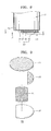
FIG. 2 is an exploded perspective view of the circuit protection assembly illustrated inFIG. 1 ; -
FIG. 3 is a top view of a secondary battery on which the circuit protection assembly illustrated inFIG. 2 is attached; -
FIG. 4 is an exploded perspective view of a circuit protection assembly according to another embodiment of the present invention; -
FIG. 5 is a top view of a secondary battery on which the circuit protection assembly illustrated inFIG. 4 is attached; -
FIG. 6 is an exploded perspective view of a circuit protection assembly according to another embodiment of the present invention; -
FIG. 7 is a bottom view of a secondary battery under which the circuit protection assembly illustrated inFIG. 6 is attached; -
FIG. 8 is a side cross-sectional view of the secondary battery illustrated inFIG. 7 ; -
FIG. 9 is an exploded perspective view of a circuit protection assembly according to another embodiment of the present invention; -
FIG. 10 is a bottom view of a secondary battery under which the circuit protection assembly illustrated inFIG. 9 is attached; -
FIG. 11 is a side cross-sectional view of the secondary battery illustrated inFIG. 10 ; -
FIG. 12 is an exploded perspective view of a circuit protection assembly according to another embodiment of the present invention; -
FIG. 13 is a side cross-sectional view of a secondary battery under which the circuit protection assembly illustrated inFIG. 12 is attached; -
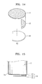
FIG. 14 is an exploded perspective view of a circuit protection assembly according to another embodiment of the present invention; -
FIG. 15 is a side cross-sectional view of a secondary battery under which the circuit protection assembly illustrated inFIG. 14 is attached; -
FIG. 16 is a side cross-sectional view of a secondary battery under which a circuit protection assembly is attached, according to another embodiment of the present invention; -
FIGS. 17A through 17D are side cross-sectional views for describing a method of manufacturing the secondary battery illustrated inFIG. 11 , according to an embodiment of the present invention; and -
FIG. 17E is a side cross-sectional view for describing a method of manufacturing the secondary battery illustrated inFIG. 15 , according to an embodiment of the present invention. - Reference will now be made in detail to embodiments, examples of which are illustrated in the accompanying drawings, wherein like reference numerals refer to like elements throughout. In this regard, the present embodiments may have different forms and should not be construed as being limited to the descriptions set forth herein. Accordingly, the embodiments are merely described below, by referring to the figures, to explain aspects of the present description.
-
FIG. 1 is a perspective view of a secondary battery on which acircuit protection assembly 10 is attached, according to an embodiment of the present invention. -
FIG. 2 is an exploded perspective view of thecircuit protection assembly 10 illustrated inFIG. 1 . - Referring to
FIGS. 1 and2 , the secondary battery according to the current embodiment includes an electrode assembly (not shown), acylindrical can 2, acap assembly 1 and acircuit protection assembly 10. Thecylindrical can 2 generally accommodates the electrode assembly, an electrolyte (not shown), an upper insulating plate (not shown) and a lower insulating plate (not shown). The electrode assembly is formed by winding a positive electrode, a separator and a negative electrode about a centre pin. The electrolyte is filled in the electrode assembly. The upper and lower insulating plates are separately disposed on and under the electrode assembly and prevent a short circuit between the electrode assembly and thecylindrical can 2. Holes through which the electrolyte is injected and a gas is emitted may be formed in the upper insulating plate. - The
cap assembly 1 is combined with thecylindrical can 2 on thecylindrical can 2 so as to seal thecylindrical can 2. Thecap assembly 1 may include a safety vent, a current interrupt device and a cap-up. - The
circuit protection assembly 10 includes a positive temperature coefficient (PTC) element or a thermal fuse as acircuit protection element 13. Thecircuit protection assembly 10 may be attached on the secondary battery, and more particularly, on a top surface of thecap assembly 1, as illustrated inFIGS. 3 and5 . Alternatively, thecircuit protection assembly 10 may be attached under the secondary battery, and more particularly, on abottom surface 2a of thecylindrical can 2, as illustrated inFIGS. 7 ,8 ,10, 11 ,13 ,15 and16 . - The
circuit protection assembly 10 according to the current embodiment includesfirst metal foil 11, thecircuit protection element 13, a supportingmember 14 andsecond metal foil 12. Thefirst metal foil 11 andsecond metal foil 12 may also be referred to as first and second metal sheets, or first and second thin metal sheets. Thefirst metal foil 11 is attached on the bottom surface of thecylindrical can 2 or the top surface of thecap assembly 1. Thecircuit protection element 13 is disposed between thefirst metal foil 11 and thesecond metal foil 12. Thecircuit protection element 13 is formed of a material that has PTC characteristics and thus functions as a PTC element. The supportingmember 14 is disposed between thefirst metal foil 11 and thesecond metal foil 12 and on a side of thecircuit protection element 13. - The
circuit protection element 13 may be a PTC element. The PTC element refers to a material obtained by mixing a polymer with a conductive material. A polymer-based conductive complex may be a mixture of a polymer, a conductive filler, an antioxidant and a peroxide crosslinking agent. The polymer may be a high-density polyethylene (HDPE), low-density polyethylene (LDPE), polyvinylidene fluoride (PVDF), polypropylene (PP) or ethylene/PP polymer having a melt index of 1 to 10. The conductive filler may be metal or metal oxide such as carbon black, carbon fiber or nickel. Although the polymer is generally an insulating material, the conductive filler allows conductive particles to be connected to each other at room or low temperature so as to provide a conductive path and thus the PTC element has excellent conductivity. If the temperature is increased above a certain level or an overcurrent flows, since the polymer in the PTC element expands, distances between the conductive particles are increased, and thus the conductive path is blocked, the conductivity of the PTC element is greatly reduced and thus PTC characteristics are manifested. - The
first metal foil 11 and thesecond metal foil 12 are formed on both surfaces of thecircuit protection element 13. Thefirst metal foil 11 and thesecond metal foil 12 maintain the shape of the PTC element and function as terminals to be electrically connected to another element. Thefirst metal foil 11 and thesecond metal foil 12 may be nickel foil, nickel-copper foil, or nickel and copper alloy foil. - An external lead plate L1 or L2 (See, for example
FIG. 8 ) may be formed of conductive metal such as nickel or nickel-plated alloy. The first orsecond metal foil circuit protection element 13 may be damaged while welding or soldering is performed. However, if the thickness of the external lead plate is maintained above a certain level, the volume of the secondary battery is increased. Accordingly, a connection method capable of preventing thecircuit protection element 13 from being damaged even when welding or soldering is performed is needed. - The
circuit protection assembly 10 formed on the secondary battery will now be described in detail with reference toFIG. 2 . Thefirst metal foil 11 has a disc shape, also referred to as a circular shape. Thesecond metal foil 12 has a partially-cut circular shape corresponding to the shape of thefirst metal foil 11. Thecircuit protection element 13 has a partially-cut ring shape corresponding to the shape of thesecond metal foil 12, and so in the plane of the circuit protection assembly, a portion of thesecond metal foil 12 extends towards a central axis of the cylindrical can from the position of theprotection element 13. Hereinafter, 'correspondence' does not refer to identical correspondence in shape. For example, when thefirst metal foil 11 and thesecond metal foil 12 have the same shape except that thesecond metal foil 12 is partially cut, the shapes of thefirst metal foil 11 and thesecond metal foil 12 are regarded as corresponding to each other. Also, when thesecond metal foil 12 and thecircuit protection element 13 have the same outer circumference despite having different shapes, the shapes of thesecond metal foil 12 and thecircuit protection element 13 are regarded as corresponding to each other. The supportingmember 14 has a partially-cut circular shape corresponding to an inner circumference of thecircuit protection element 13. -
FIG. 3 is a top view of a secondary battery on which thecircuit protection assembly 10 illustrated inFIG. 2 is attached. Referring toFIG. 3 , thefirst metal foil 11 is partially exposed and thesecond metal foil 12 is more exposed, because thecircuit protection element 13 and the supportingmember 14 are smaller than thefirst metal foil 11. If an external lead plate L1 or L2 formed on the secondary battery contacts thesecond metal foil 12, a current flows through thecircuit protection element 13. On the other hand, if the external lead plate contacts the exposed portion of thefirst metal foil 11, the current flows without passing through thecircuit protection element 13. Thus, as needed, one secondary battery may be used in both a product that requires thecircuit protection assembly 10 and a product that does not. In more detail, since one standardized secondary battery may have both high-output and high-capacity characteristics according to necessity, a high-output battery and a high-capacity battery need not be separately manufactured. Alternatively, thecircuit protection element 13 may be added on or under a bare cell according to the type of product using the secondary battery. As such, a secondary battery not including thecircuit protection element 13 is used in a product that requires a high output, e.g., an electric bicycle, an electric scooter or a power tool, and a secondary battery including thecircuit protection element 13 may be used in a product that requires safety and a mild operation environment, e.g., a notebook computer. As such, different secondary batteries may not need to be manufactured for different products. -
FIG. 4 is an exploded perspective view of acircuit protection assembly 20 to be attached on a secondary battery, according to another embodiment of the present invention. - Referring to
FIG. 4 ,first metal foil 21 has a circular shape.Second metal foil 22 has a partially-cut circular shape corresponding to the shape of thefirst metal foil 21. Acircuit protection element 23 has a partially-cut circular shape corresponding to the shape of the first orsecond metal foil second metal foil 22. A supportingmember 24 has a circular shape cut on two sides, corresponding to the shape of thesecond metal foil 22. -
FIG. 5 is a top view of a secondary battery on which thecircuit protection assembly 20 illustrated inFIG. 4 is attached. - Referring to
FIG. 5 , an exposed portion of thefirst metal foil 21 may have an area that is sufficient to be welded to an external lead plate L1 or L2. The shape of a combination of thecircuit protection element 23 and the supportingmember 24 corresponds to the shape of thesecond metal foil 22, but is not limited thereto. For example, thesecond metal foil 22 may have a shape for entirely covering thecircuit protection element 23 and partially covering the supportingmember 24, because the supportingmember 24 is used to support thesecond metal foil 22 when thesecond metal foil 22 is welded to the external lead plate and thus may have an area that is sufficient to be welded. -
FIG. 6 is an exploded perspective view of acircuit protection assembly 30 to be attached under a secondary battery, according to another embodiment of the present invention. - Referring to
FIG. 6 ,first metal foil 31 has a circular shape.Second metal foil 32 has a partially-cut circular shape corresponding to the shape of thefirst metal foil 31. Acircuit protection element 33 has a partially-cut ring shape corresponding to the shape of the first orsecond metal foil member 34 has a partially-cut circular shape corresponding to an inner circumference of thecircuit protection element 33. -
FIG. 7 is a bottom view of a secondary battery under which thecircuit protection assembly 30 illustrated inFIG. 6 is attached.FIG. 8 is a side cross-sectional view of the secondary battery illustrated inFIG. 7 . - Referring to
FIGS. 7 and8 , thefirst metal foil 31 is partially exposed and thesecond metal foil 32 is entirely exposed. If an external lead plate L1 or L2 formed under the secondary battery contacts thesecond metal foil 32, a current flows through the circuit protection element 33 (see L2). On the other hand, if the external lead plate contacts the exposed portion of thefirst metal foil 31, the current flows without passing through the circuit protection element 33 (see L1). - Thus, according to necessity, one secondary battery may be used in both a product that requires the
circuit protection assembly 30 and a product that does not. -
FIG. 9 is an exploded perspective view of acircuit protection assembly 40 to be attached under a secondary battery, according to another embodiment of the present invention. - Referring to
FIG. 9 ,first metal foil 41 has a circular shape.Second metal foil 42 has a partially-cut circular shape corresponding to the shape of thefirst metal foil 41. Acircuit protection element 43 has a partially-cut circular shape corresponding to the shape of the first orsecond metal foil second metal foil 42. A supportingmember 44 has a circular shape cut on two sides, corresponding to the shape of thesecond metal foil 42. -
FIG. 10 is a bottom view of a secondary battery under which thecircuit protection assembly 40 illustrated inFIG. 9 is attached.FIG. 11 is a side cross-sectional view of the secondary battery illustrated inFIG. 10 . - Referring to
FIGS. 10 and 11 , an exposed portion of thefirst metal foil 41 may have an area that is sufficient to be welded to an external lead plate L1 or L2. The shape of a combination of thecircuit protection element 43 and the supportingmember 44 corresponds to the shape of thesecond metal foil 42, but is not limited thereto. For example, thesecond metal foil 42 may have a shape for entirely covering thecircuit protection element 43 and partially covering the supportingmember 44, because the supportingmember 44 is used to support thesecond metal foil 42 when thesecond metal foil 42 is welded to the external lead plate and thus may have an area that is sufficient to be welded. -
FIG. 12 is an exploded perspective view of acircuit protection assembly 50 to be attached under a secondary battery, according to another embodiment of the present invention. - Referring to
FIG. 12 , thecircuit protection assembly 50 is different from thecircuit protection assembly 30 illustrated inFIG. 6 in thatfirst metal foil 51 has a ring shape instead of a disc shape and that the thickness of a supporting member 54 (d1+d2) equals the sum of the thickness of the first metal foil 51 (d2) and the thickness of a circuit protection element 53 (d1). Accordingly, as illustrated inFIG. 13 , one surface of the supportingmember 54 directly contacts abottom surface 2a of acylindrical can 2. -
FIG. 14 is an exploded perspective view of acircuit protection assembly 60 according to another embodiment of the present invention. - Referring to
FIG. 14 ,first metal foil 61 has a circular shape.Second metal foil 62 has a partially-cut circular shape corresponding to the shape of thefirst metal foil 61. Acircuit protection element 63 has a partially-cut circular shape corresponding to the shape of the first orsecond metal foil second metal foil 62. Thecircuit protection assembly 60 is different from the previous embodiments in that a supporting member is not included. Accordingly, as illustrated inFIG. 15 , an empty space exists between thefirst metal foil 61 and thesecond metal foil 62. A portion of thesecond metal foil 62 corresponding to the empty space is combined with an external lead plate L1 or L2 by using, for example, a welding method. In this case, awelding jig 90 illustrated inFIG. 17E may be used to support thesecond metal foil 62. - Although the circuit
protection element assemblies FIGS. 12 through 15 , the position of the circuitprotection element assemblies protection element assemblies cap assembly 1 illustrated inFIG. 1 . -
FIG. 16 is a side cross-sectional view of a secondary battery under which acircuit protection assembly 70 is attached, according to another embodiment of the present invention. - Referring to
FIG. 16 , thecircuit protection assembly 70 is different from the previous embodiments in that acircuit protection element 73 is a thermal fuse. A PTC element interrupts a circuit as the resistance of the PTC element is greatly increased in a predetermined condition, for example, at a temperature higher than a certain level. However, if the temperature is lowered below the certain level, the resistance is reduced and thus the PTC element returns to an original state and thus is reusable. On the other hand, a thermal fuse interrupts a circuit as a conductive wire of the thermal fuse is cut at a temperature higher than a certain level and thus is not reusable. That is, like the PTC element, thethermal fuse 73 interrupts a circuit when the temperature of a secondary battery is greatly increased in an abnormal environment or under abnormal conditions. However, when this occurs, thecircuit protection assembly 70 needs to be changed in order to protect against damage and performance deterioration. -
FIGS. 17A through 17D are side cross-sectional views for describing a method of manufacturing the secondary battery illustrated inFIG. 11 , according to an embodiment of the present invention. - Initially, a
cylindrical can 2 is prepared (FIG. 17A ). In this case, thecylindrical can 2 may accommodate an electrode assembly and an electrolyte, and may be sealed by using a cap assembly. Alternatively, thecylindrical can 2 may not accommodate anything. - A
circuit protection assembly 40 is attached on a bottom surface of the cylindrical can 2 (FIG. 17B ). An attaching method may be a welding method, and more particularly, a resistance welding method, or a soldering method or a method using a conductive adhesive. If the resistance welding method is used, thecylindrical can 2 is welded to a portion offirst metal foil 41, on which acircuit protection element 43 is not attached, and is also welded to a portion of thefirst metal foil 41, which does not correspond tosecond metal foil 42, because thecylindrical can 2 is generally attached to thefirst metal foil 41 after thecircuit protection assembly 40 is formed. The number of welding points W1 can be one and may be equal to or greater than two. - A supporting
member 44 is disposed between thefirst metal foil 41 and the second metal foil 42 (FIG. 17C ). The supportingmember 44 may be disposed and then fixed. For this, the supportingmember 44 may be inserted and then fixed by using, for example, a non-conductive adhesive. The supportingmember 44 may contact a side surface of thecircuit protection element 43 or may be separate from thecircuit protection element 43. The supportingmember 44 is used to support thesecond metal foil 42 when thesecond metal foil 42 is welded to anexternal lead plate 100 illustrated inFIG. 17D and thus is not always required to contact the side surface thecircuit protection element 43. The supportingmember 44 is an insulator. If the supportingmember 44 is a conductor, when a current flows between thefirst metal foil 41 and thesecond metal foil 42, the supportingmember 44 may allow the current to flow through only the supportingmember 44 without passing through thecircuit protection element 43 and thus thecircuit protection element 43 may not function as a PTC element. - Then, the
external lead plate 100 is welded to the second metal foil 42 (FIG. 17D ). The number of welding points W2 may be equal to or greater than two, but is not limited thereto. Thesecond metal foil 42 is pressed when resistance welding is performed, which ensures the welding to be firmly performed without deformation of thesecond metal foil 42 as the supportingmember 44 supports thesecond metal foil 42. As such, damage to thecircuit protection element 43 may be prevented by welding theexternal lead plate 100 to a portion of thesecond metal foil 42 corresponding to the supportingmember 14 instead of to a portion of thesecond metal foil 42 corresponding to thecircuit protection element 43. As theexternal lead plate 100 contacts thesecond metal foil 42, a discharge circuit of the secondary battery includes thecircuit protection element 43 and thus the secondary battery is appropriate for an electronic device that requires safety and high-capacity characteristics. - Although the
circuit protection assembly 40 is directly connected to theexternal lead plate 10 inFIG. 17D , thecircuit protection assembly 40 may further include an additional conductive plate such as a nickel strip on thesecond metal foil 42. - As described above in relation to
FIG. 3 , if theexternal lead plate 100 contacts thefirst metal foil 41, the discharge circuit of the secondary battery does not include thecircuit protection element 43 and thus the secondary battery is appropriate for an electronic device that requires high-output characteristics. -
FIG. 17E is a side cross-sectional view for describing a method of manufacturing the secondary battery illustrated inFIG. 15 , according to an embodiment of the present invention. - Operations performed in
FIGS. 17A and 17B are also performed and then anarm 90b of awelding jig 90 is inserted betweenfirst metal foil 61 andsecond metal foil 62. Then, welding rods (not shown) are inserted intoholes 90a formed in thewelding jig 90 and an external lead plate is welded to thesecond metal foil 62. The length and thickness of thearm 90b of thewelding jig 90 and the size of theholes 90a of thewelding jig 90 are designed to be appropriate for a rapid welding operation. - A secondary battery according to one or more of the above embodiments of the present invention may also be applied to an oval secondary battery or a rectangular secondary battery as well as a cylindrical secondary battery. That is, the shape of the secondary battery does not matter. The secondary battery may be applied to all batteries having a capacity equal to or greater than about 2,000 mAh or batteries having an output equal to or greater than about 7 C. Here, a battery having an output of 7 C refers to a battery capable of outputting a current of 14,000 mA that is seven times of a capacity of, for example, 2,000 mAh. Although a rectangular battery having a high output equal to or greater than 7 C does not currently exist, if such a rectangular battery is developed, the rectangular battery is also included in the scope of the present invention. Also, the shapes of the
first metal foil second metal foil FIG. 2 ,4 ,6 ,9 ,12 ,14 or16 may be appropriately changed according to the shape of the secondary battery. Furthermore, 2000 mAh and 7 C used as reference values to describe a high output and a high capacity may also be easily changed by one of ordinary skill in the art. - It should be understood that the exemplary embodiments described herein should be considered in a descriptive sense only and not for purposes of limitation. Descriptions of features or aspects within each embodiment should typically be considered as available for other similar features or aspects in other embodiments.
Claims (15)
- A secondary battery comprising:a can for accommodating an electrode assembly and an electrolyte;a cap assembly mounted on the can;first metal foil attached on a top surface of the cap assembly or a bottom surface of the can;a circuit protection element attached on the first metal foil; andsecond metal foil attached on the circuit protection element,wherein the second metal foil is configured such that a portion of the second metal foil does not overlap the circuit protection element.
- The secondary battery of claim 1, wherein the secondary battery has a cylindrical shape, in which the can is a cylindrical can, and wherein a portion of the second metal foil may extend toward a central axis of the cylindrical can from the circuit protection element.
- The secondary battery of claim 1 or claim 2, wherein the circuit protection element is a positive temperature coefficient (PTC) element or a thermal fuse.
- The secondary battery of any one of the preceding claims, further comprising a supporting member disposed on a side of the circuit protection element, the supporting member being in surface-contact with at least a portion of the second metal foil, in which the supporting member may be an electrical insulator.
- The secondary battery of claim 4, wherein the circuit protection element, the supporting member and the second metal foil are configured such that at least a portion of one surface of the first metal foil is exposed.
- The secondary battery of claim 4 or claim 5, wherein the first metal foil has a disc shape,
wherein the circuit protection element has at least a partial ring shape,
wherein the supporting member has a shape corresponding to at least a portion of a hole formed in the at least partial ring shape of the circuit protection element, and
wherein the second metal foil has a shape for covering the circuit protection element and the supporting member. - The secondary battery of claim 4 or claim 5, wherein the first metal foil has a ring shape,
wherein the circuit protection element has a partially-cut ring shape corresponding to the ring shape of the first metal foil,
wherein the supporting member has a shape corresponding to at least a portion of a hole formed in the partially-cut ring shape of the circuit protection element, and
wherein the second metal foil has a partially-cut disc shape corresponding to the circuit protection element and the supporting member. - The secondary battery of claim 4 or claim 5, wherein the first metal foil has a disc shape,
wherein the circuit protection element has a partially-cut disc shape corresponding to the disc shape of the first metal foil,
wherein the supporting member has a disc shape cut on two sides, and
wherein the second metal foil has a shape corresponding to a combination of the circuit protection element and the supporting member. - The secondary battery of claim 4 or claim 5, wherein the second metal foil is welded to an external tab for electrical connection, and
wherein a portion of the second metal foil corresponding to the supporting member is welded to the external tab. - The secondary battery of any one of the preceding claims, wherein the secondary battery has a capacity equal to or greater than 2,000 mAh or an output equal to or greater than 14,000 mA.
- A method of manufacturing a secondary battery, the method comprising:preparing a can for accommodating an electrode assembly and an electrolyte, and a cap assembly mounted on the can; andattaching a circuit protection assembly formed by stacking first metal foil, a circuit protection element and second metal foil, on a bottom surface of the can or a top surface of the cap assembly;wherein the second metal foil is stacked such that a portion of the second metal foil does not overlap the circuit protection element.
- The method of claim 11, further comprising attaching an external tab to the portion of the second metal foil which does not overlap the circuit protection element, for electrical connection.
- The method of claim 12, further comprising disposing a supporting member on a side of the circuit protection element, the supporting member being in surface-contact with the second metal foil, and
wherein the portion of the second metal foil to which the external tab is attached overlaps the supporting member. - The method of claim 13, further comprising disposing a welding jig, which may be an electrical insulator, on a side of the circuit protection element so as to be in surface-contact with the first metal foil,
wherein the attaching of the external tab comprises welding the external tab to a portion of the second metal foil corresponding to the supporting member. - The method of claim 13 or claim 14, wherein the attaching of the circuit protection assembly comprises welding a portion of the first metal foil not corresponding to the circuit protection element on the bottom surface of the can or the top surface of the cap assembly.
Applications Claiming Priority (2)
| Application Number | Priority Date | Filing Date | Title |
|---|---|---|---|
| KR1020090110364A KR101108179B1 (en) | 2009-11-16 | 2009-11-16 | Secondary Battery and Manufacturing Method Thereof |
| KR1020090110363A KR101097251B1 (en) | 2009-11-16 | 2009-11-16 | Safety Device Assembly |
Publications (3)
| Publication Number | Publication Date |
|---|---|
| EP2323200A2 true EP2323200A2 (en) | 2011-05-18 |
| EP2323200A3 EP2323200A3 (en) | 2011-10-05 |
| EP2323200B1 EP2323200B1 (en) | 2016-12-28 |
Family
ID=43618263
Family Applications (2)
| Application Number | Title | Priority Date | Filing Date |
|---|---|---|---|
| EP10190230.2A Active EP2323200B1 (en) | 2009-11-16 | 2010-11-05 | Secondary battery and method of manufacturing the same |
| EP10190234.4A Active EP2323199B1 (en) | 2009-11-16 | 2010-11-05 | Safety element assembly |
Family Applications After (1)
| Application Number | Title | Priority Date | Filing Date |
|---|---|---|---|
| EP10190234.4A Active EP2323199B1 (en) | 2009-11-16 | 2010-11-05 | Safety element assembly |
Country Status (4)
| Country | Link |
|---|---|
| US (2) | US9105918B2 (en) |
| EP (2) | EP2323200B1 (en) |
| JP (2) | JP5385218B2 (en) |
| CN (2) | CN102064355B (en) |
Families Citing this family (17)
| Publication number | Priority date | Publication date | Assignee | Title |
|---|---|---|---|---|
| JP5385218B2 (en) * | 2009-11-16 | 2014-01-08 | 三星エスディアイ株式会社 | Usage of secondary battery |
| CN103093872B (en) * | 2011-11-07 | 2016-04-06 | 瑞侃电子(上海)有限公司 | A kind of circuit brake, installation method and battery |
| JP5797091B2 (en) * | 2011-11-08 | 2015-10-21 | Fdk鳥取株式会社 | External PTC element unit and battery |
| KR101934399B1 (en) * | 2011-11-14 | 2019-01-02 | 삼성에스디아이 주식회사 | Battery pack with protection circuit module and connection terminal portion and electric bike having the same |
| WO2014129462A1 (en) * | 2013-02-20 | 2014-08-28 | タイコエレクトロニクスジャパン合同会社 | Opening sealing body |
| JP6454542B2 (en) * | 2014-12-26 | 2019-01-16 | Fdk株式会社 | External PTC element and cylindrical battery |
| WO2016197568A1 (en) * | 2015-06-12 | 2016-12-15 | 福建南平南孚电池有限公司 | Electrochemical secondary battery having inbuilt charging circuit |
| CN106556468A (en) * | 2015-09-25 | 2017-04-05 | 株式会社村田制作所 | Thermistor component with lead and its manufacture method |
| CN105670550B (en) * | 2016-03-31 | 2017-11-14 | 东莞新能源科技有限公司 | Heat-conducting glue and secondary battery containing same |
| KR20190035762A (en) * | 2016-08-15 | 2019-04-03 | 리텔퓨즈 인코퍼레이티드 | Flexible Constant Temperature Coefficient with Battery Management System |
| US9837682B1 (en) * | 2016-08-29 | 2017-12-05 | Microsoft Technology Licensing, Llc | Variable layer thickness in curved battery cell |
| WO2018168043A1 (en) * | 2017-03-14 | 2018-09-20 | 株式会社村田製作所 | Lithium-ion secondary cell |
| US10950912B2 (en) | 2017-06-14 | 2021-03-16 | Milwaukee Electric Tool Corporation | Arrangements for inhibiting intrusion into battery pack electrical components |
| CN110518296A (en) * | 2019-08-30 | 2019-11-29 | 广州华其电子有限公司 | A kind of anti-overcharge nickel-metal hydride battery of high-capacity intelligent protection type |
| KR102820188B1 (en) | 2020-05-13 | 2025-06-13 | 주식회사 엘지에너지솔루션 | Battery Pack With Fuse-Box Bracket of Preventing Short Circuit |
| USD1110940S1 (en) * | 2022-07-18 | 2026-02-03 | Xiamen Hithium Energy Storage Technology Co., Ltd. | Battery cover |
| USD1086987S1 (en) * | 2022-08-17 | 2025-08-05 | Xiamen Hithium Energy Storage Technology Co., Ltd. | Battery cover |
Family Cites Families (42)
| Publication number | Priority date | Publication date | Assignee | Title |
|---|---|---|---|---|
| US400643A (en) * | 1889-04-02 | Metallic railway-tie and fastening | ||
| US4006443A (en) | 1975-09-11 | 1977-02-01 | Allen-Bradley Company | Composition resistor with an integral thermal fuse |
| JPH0834098B2 (en) * | 1989-02-07 | 1996-03-29 | 日立マクセル株式会社 | Cylindrical organic electrolyte battery with PTC element |
| JP2898336B2 (en) * | 1989-05-18 | 1999-05-31 | 株式会社フジクラ | Manufacturing method of PTC thermistor |
| AU637370B2 (en) * | 1989-05-18 | 1993-05-27 | Fujikura Ltd. | Ptc thermistor and manufacturing method for the same |
| JPH0638157A (en) | 1992-07-17 | 1994-02-10 | Hitachi Ltd | Video camera |
| JP2585011Y2 (en) * | 1992-10-29 | 1998-11-11 | 三洋電機株式会社 | Switching means and battery pack incorporating switching means |
| JPH0765856A (en) | 1993-08-23 | 1995-03-10 | Toshiba Corp | PTC element and secondary battery using the same |
| JPH0741974U (en) * | 1993-12-22 | 1995-07-21 | 株式会社エイ・ティーバッテリー | Charge / discharge control means |
| EP0844622B1 (en) * | 1995-08-07 | 2004-06-09 | Tyco Electronics Raychem K.K. | Ptc device and battery pack using the same |
| US5939968A (en) | 1996-06-19 | 1999-08-17 | Littelfuse, Inc. | Electrical apparatus for overcurrent protection of electrical circuits |
| US5808538A (en) | 1996-06-19 | 1998-09-15 | Littelfuse, Inc. | Electrical apparatus for overcurrent protection of electrical circuits |
| US5703463A (en) | 1997-02-18 | 1997-12-30 | National Semiconductor Corporation | Methods and apparatus for protecting battery cells from overcharge |
| JP3576767B2 (en) * | 1997-09-18 | 2004-10-13 | タイコ エレクトロニクス レイケム株式会社 | Battery pack and PTC element built in this battery pack |
| GB9820132D0 (en) * | 1998-09-16 | 1998-11-11 | Raychem Ltd | Battery over-discharge protection |
| JP3625691B2 (en) * | 1999-05-27 | 2005-03-02 | 三洋電機株式会社 | Pack battery |
| TW543258B (en) * | 2001-10-08 | 2003-07-21 | Polytronics Technology Corp | Over current protection apparatus and its manufacturing method |
| JP5073204B2 (en) * | 2003-03-07 | 2012-11-14 | タイコエレクトロニクスジャパン合同会社 | Polymer PTC element |
| KR100515354B1 (en) | 2003-06-19 | 2005-09-15 | 삼성에스디아이 주식회사 | Secondary battery |
| JP4243148B2 (en) | 2003-07-31 | 2009-03-25 | 三洋電機株式会社 | Sealed storage battery |
| WO2005029513A2 (en) * | 2003-09-22 | 2005-03-31 | Tyco Electronics Raychem Kk | Thermistor |
| US7943251B2 (en) * | 2004-10-28 | 2011-05-17 | Samsung Sdi Co., Ltd. | Rechargeable battery having safety vent |
| KR101253380B1 (en) * | 2005-05-16 | 2013-04-11 | 타이코 일렉트로닉스 레이켐 케이. 케이. | Sealing body and cell pack using the same |
| CN2899126Y (en) * | 2005-12-16 | 2007-05-09 | 比亚迪股份有限公司 | A cylindrical lithium-ion battery |
| CN100573978C (en) * | 2005-12-30 | 2009-12-23 | 比亚迪股份有限公司 | secondary battery |
| JP2007184138A (en) | 2006-01-05 | 2007-07-19 | Sony Corp | Current control mechanism and battery |
| KR100770111B1 (en) * | 2006-01-18 | 2007-10-24 | 삼성에스디아이 주식회사 | Cylindrical Lithium Secondary Battery |
| KR100804893B1 (en) | 2006-02-10 | 2008-02-20 | 엘에스전선 주식회사 | Connection structure of battery cap and PCC and secondary battery using same |
| TWI298598B (en) * | 2006-02-15 | 2008-07-01 | Polytronics Technology Corp | Over-current protection device |
| JP2008071828A (en) * | 2006-09-12 | 2008-03-27 | Tdk Corp | Ptc element and battery protection system |
| JP2008091505A (en) | 2006-09-29 | 2008-04-17 | Tdk Corp | Ptc element and battery protection system |
| JP5498645B2 (en) * | 2006-10-02 | 2014-05-21 | 三星エスディアイ株式会社 | Lithium secondary battery |
| KR100846956B1 (en) | 2006-11-21 | 2008-07-17 | 삼성에스디아이 주식회사 | Secondary Battery with Protection Circuit Module |
| JP4453708B2 (en) | 2007-02-26 | 2010-04-21 | ソニー株式会社 | battery |
| US8501342B2 (en) * | 2007-04-11 | 2013-08-06 | Samsung Sdi Co., Ltd. | Rechargeable battery with an antenna assembly |
| KR100922468B1 (en) * | 2007-09-21 | 2009-10-21 | 삼성에스디아이 주식회사 | Battery pack |
| KR100867923B1 (en) | 2007-10-30 | 2008-11-10 | 삼성에스디아이 주식회사 | Secondary Battery with Protective Circuit Board |
| KR100954587B1 (en) * | 2007-11-08 | 2010-04-26 | 삼성에스디아이 주식회사 | Cap assembly and secondary battery having the same |
| KR101130048B1 (en) | 2007-11-29 | 2012-03-28 | 주식회사 엘지화학 | Secondary Battery Pack Having PCM Assembly of Novel Structure |
| US8304116B2 (en) * | 2008-10-02 | 2012-11-06 | The Gillette Company | Battery |
| US9023513B2 (en) * | 2009-08-27 | 2015-05-05 | Samsung Sdi Co., Ltd. | Rechargeable secondary battery having improved safety against puncture and collapse |
| JP5385218B2 (en) * | 2009-11-16 | 2014-01-08 | 三星エスディアイ株式会社 | Usage of secondary battery |
-
2010
- 2010-06-22 JP JP2010141573A patent/JP5385218B2/en active Active
- 2010-07-27 US US12/844,676 patent/US9105918B2/en active Active
- 2010-07-27 US US12/844,681 patent/US9406923B2/en active Active
- 2010-08-02 JP JP2010173709A patent/JP5235949B2/en not_active Expired - Fee Related
- 2010-11-05 EP EP10190230.2A patent/EP2323200B1/en active Active
- 2010-11-05 EP EP10190234.4A patent/EP2323199B1/en active Active
- 2010-11-16 CN CN201010551672.3A patent/CN102064355B/en active Active
- 2010-11-16 CN CN201010551684.6A patent/CN102064304B/en active Active
Non-Patent Citations (1)
| Title |
|---|
| None |
Also Published As
| Publication number | Publication date |
|---|---|
| CN102064304A (en) | 2011-05-18 |
| JP2011108630A (en) | 2011-06-02 |
| EP2323200A3 (en) | 2011-10-05 |
| JP2011108625A (en) | 2011-06-02 |
| EP2323199A3 (en) | 2011-10-05 |
| JP5235949B2 (en) | 2013-07-10 |
| US20110117390A1 (en) | 2011-05-19 |
| EP2323200B1 (en) | 2016-12-28 |
| CN102064355A (en) | 2011-05-18 |
| EP2323199A2 (en) | 2011-05-18 |
| JP5385218B2 (en) | 2014-01-08 |
| US20110117400A1 (en) | 2011-05-19 |
| US9406923B2 (en) | 2016-08-02 |
| US9105918B2 (en) | 2015-08-11 |
| CN102064355B (en) | 2015-02-11 |
| CN102064304B (en) | 2015-03-11 |
| EP2323199B1 (en) | 2020-05-06 |
Similar Documents
| Publication | Publication Date | Title |
|---|---|---|
| EP2323200B1 (en) | Secondary battery and method of manufacturing the same | |
| KR100922474B1 (en) | Secondary battery | |
| US7811686B2 (en) | Rechargeable battery | |
| EP2164121B1 (en) | Protection circuit board, secondary battery and battery pack | |
| US8883331B2 (en) | Protective circuit module and rechargeable battery including the same | |
| US9685681B2 (en) | Battery pack | |
| CN100544068C (en) | Battery module | |
| KR100938896B1 (en) | Battery pack | |
| CN100474663C (en) | Rechargeable battery | |
| KR102283960B1 (en) | Battery pack | |
| KR102261183B1 (en) | Cable type battery | |
| US8586221B2 (en) | Rechargeable battery with protective circuit board lead plates connection | |
| KR20180090100A (en) | Short circuiting Structure for Lithium Secondary Battery Having Excellent Stability against Overcharge and Pouch Type Lithium Secondary Battery Comprising the Same | |
| KR102198797B1 (en) | Rechargeable battery pack | |
| KR102555490B1 (en) | Rechargeable battery pack | |
| KR100804893B1 (en) | Connection structure of battery cap and PCC and secondary battery using same | |
| EP2372827A1 (en) | Sencodary battery pack | |
| KR101108179B1 (en) | Secondary Battery and Manufacturing Method Thereof | |
| KR100803435B1 (en) | Ptc element that can be installed in battery cap and secondary battery using same | |
| KR101097251B1 (en) | Safety Device Assembly | |
| KR100659857B1 (en) | Pack case of secondary battery | |
| KR20070081301A (en) | Protective element mountable to battery cap and secondary battery having same |
Legal Events
| Date | Code | Title | Description |
|---|---|---|---|
| PUAI | Public reference made under article 153(3) epc to a published international application that has entered the european phase |
Free format text: ORIGINAL CODE: 0009012 |
|
| 17P | Request for examination filed |
Effective date: 20101105 |
|
| AK | Designated contracting states |
Kind code of ref document: A2 Designated state(s): AL AT BE BG CH CY CZ DE DK EE ES FI FR GB GR HR HU IE IS IT LI LT LU LV MC MK MT NL NO PL PT RO RS SE SI SK SM TR |
|
| AX | Request for extension of the european patent |
Extension state: BA ME |
|
| PUAL | Search report despatched |
Free format text: ORIGINAL CODE: 0009013 |
|
| AK | Designated contracting states |
Kind code of ref document: A3 Designated state(s): AL AT BE BG CH CY CZ DE DK EE ES FI FR GB GR HR HU IE IS IT LI LT LU LV MC MK MT NL NO PL PT RO RS SE SI SK SM TR |
|
| AX | Request for extension of the european patent |
Extension state: BA ME |
|
| RIC1 | Information provided on ipc code assigned before grant |
Ipc: H01M 2/34 20060101AFI20110831BHEP Ipc: H01M 10/04 20060101ALI20110831BHEP |
|
| GRAP | Despatch of communication of intention to grant a patent |
Free format text: ORIGINAL CODE: EPIDOSNIGR1 |
|
| RIC1 | Information provided on ipc code assigned before grant |
Ipc: H01M 10/04 20060101ALI20160513BHEP Ipc: H01M 2/34 20060101AFI20160513BHEP Ipc: H01M 2/04 20060101ALN20160513BHEP |
|
| INTG | Intention to grant announced |
Effective date: 20160622 |
|
| GRAS | Grant fee paid |
Free format text: ORIGINAL CODE: EPIDOSNIGR3 |
|
| GRAA | (expected) grant |
Free format text: ORIGINAL CODE: 0009210 |
|
| AK | Designated contracting states |
Kind code of ref document: B1 Designated state(s): AL AT BE BG CH CY CZ DE DK EE ES FI FR GB GR HR HU IE IS IT LI LT LU LV MC MK MT NL NO PL PT RO RS SE SI SK SM TR |
|
| REG | Reference to a national code |
Ref country code: GB Ref legal event code: FG4D |
|
| REG | Reference to a national code |
Ref country code: CH Ref legal event code: EP |
|
| REG | Reference to a national code |
Ref country code: AT Ref legal event code: REF Ref document number: 857980 Country of ref document: AT Kind code of ref document: T Effective date: 20170115 |
|
| REG | Reference to a national code |
Ref country code: IE Ref legal event code: FG4D |
|
| REG | Reference to a national code |
Ref country code: DE Ref legal event code: R096 Ref document number: 602010039111 Country of ref document: DE |
|
| PG25 | Lapsed in a contracting state [announced via postgrant information from national office to epo] |
Ref country code: LV Free format text: LAPSE BECAUSE OF FAILURE TO SUBMIT A TRANSLATION OF THE DESCRIPTION OR TO PAY THE FEE WITHIN THE PRESCRIBED TIME-LIMIT Effective date: 20161228 |
|
| REG | Reference to a national code |
Ref country code: LT Ref legal event code: MG4D |
|
| PG25 | Lapsed in a contracting state [announced via postgrant information from national office to epo] |
Ref country code: NO Free format text: LAPSE BECAUSE OF FAILURE TO SUBMIT A TRANSLATION OF THE DESCRIPTION OR TO PAY THE FEE WITHIN THE PRESCRIBED TIME-LIMIT Effective date: 20170328 Ref country code: LT Free format text: LAPSE BECAUSE OF FAILURE TO SUBMIT A TRANSLATION OF THE DESCRIPTION OR TO PAY THE FEE WITHIN THE PRESCRIBED TIME-LIMIT Effective date: 20161228 Ref country code: GR Free format text: LAPSE BECAUSE OF FAILURE TO SUBMIT A TRANSLATION OF THE DESCRIPTION OR TO PAY THE FEE WITHIN THE PRESCRIBED TIME-LIMIT Effective date: 20170329 Ref country code: SE Free format text: LAPSE BECAUSE OF FAILURE TO SUBMIT A TRANSLATION OF THE DESCRIPTION OR TO PAY THE FEE WITHIN THE PRESCRIBED TIME-LIMIT Effective date: 20161228 |
|
| REG | Reference to a national code |
Ref country code: NL Ref legal event code: MP Effective date: 20161228 |
|
| REG | Reference to a national code |
Ref country code: AT Ref legal event code: MK05 Ref document number: 857980 Country of ref document: AT Kind code of ref document: T Effective date: 20161228 |
|
| PG25 | Lapsed in a contracting state [announced via postgrant information from national office to epo] |
Ref country code: RS Free format text: LAPSE BECAUSE OF FAILURE TO SUBMIT A TRANSLATION OF THE DESCRIPTION OR TO PAY THE FEE WITHIN THE PRESCRIBED TIME-LIMIT Effective date: 20161228 Ref country code: FI Free format text: LAPSE BECAUSE OF FAILURE TO SUBMIT A TRANSLATION OF THE DESCRIPTION OR TO PAY THE FEE WITHIN THE PRESCRIBED TIME-LIMIT Effective date: 20161228 Ref country code: HR Free format text: LAPSE BECAUSE OF FAILURE TO SUBMIT A TRANSLATION OF THE DESCRIPTION OR TO PAY THE FEE WITHIN THE PRESCRIBED TIME-LIMIT Effective date: 20161228 |
|
| PG25 | Lapsed in a contracting state [announced via postgrant information from national office to epo] |
Ref country code: NL Free format text: LAPSE BECAUSE OF FAILURE TO SUBMIT A TRANSLATION OF THE DESCRIPTION OR TO PAY THE FEE WITHIN THE PRESCRIBED TIME-LIMIT Effective date: 20161228 |
|
| PG25 | Lapsed in a contracting state [announced via postgrant information from national office to epo] |
Ref country code: EE Free format text: LAPSE BECAUSE OF FAILURE TO SUBMIT A TRANSLATION OF THE DESCRIPTION OR TO PAY THE FEE WITHIN THE PRESCRIBED TIME-LIMIT Effective date: 20161228 Ref country code: CZ Free format text: LAPSE BECAUSE OF FAILURE TO SUBMIT A TRANSLATION OF THE DESCRIPTION OR TO PAY THE FEE WITHIN THE PRESCRIBED TIME-LIMIT Effective date: 20161228 Ref country code: SK Free format text: LAPSE BECAUSE OF FAILURE TO SUBMIT A TRANSLATION OF THE DESCRIPTION OR TO PAY THE FEE WITHIN THE PRESCRIBED TIME-LIMIT Effective date: 20161228 Ref country code: IS Free format text: LAPSE BECAUSE OF FAILURE TO SUBMIT A TRANSLATION OF THE DESCRIPTION OR TO PAY THE FEE WITHIN THE PRESCRIBED TIME-LIMIT Effective date: 20170428 Ref country code: RO Free format text: LAPSE BECAUSE OF FAILURE TO SUBMIT A TRANSLATION OF THE DESCRIPTION OR TO PAY THE FEE WITHIN THE PRESCRIBED TIME-LIMIT Effective date: 20161228 |
|
| PG25 | Lapsed in a contracting state [announced via postgrant information from national office to epo] |
Ref country code: SM Free format text: LAPSE BECAUSE OF FAILURE TO SUBMIT A TRANSLATION OF THE DESCRIPTION OR TO PAY THE FEE WITHIN THE PRESCRIBED TIME-LIMIT Effective date: 20161228 Ref country code: IT Free format text: LAPSE BECAUSE OF FAILURE TO SUBMIT A TRANSLATION OF THE DESCRIPTION OR TO PAY THE FEE WITHIN THE PRESCRIBED TIME-LIMIT Effective date: 20161228 Ref country code: AT Free format text: LAPSE BECAUSE OF FAILURE TO SUBMIT A TRANSLATION OF THE DESCRIPTION OR TO PAY THE FEE WITHIN THE PRESCRIBED TIME-LIMIT Effective date: 20161228 Ref country code: BG Free format text: LAPSE BECAUSE OF FAILURE TO SUBMIT A TRANSLATION OF THE DESCRIPTION OR TO PAY THE FEE WITHIN THE PRESCRIBED TIME-LIMIT Effective date: 20170328 Ref country code: ES Free format text: LAPSE BECAUSE OF FAILURE TO SUBMIT A TRANSLATION OF THE DESCRIPTION OR TO PAY THE FEE WITHIN THE PRESCRIBED TIME-LIMIT Effective date: 20161228 Ref country code: PL Free format text: LAPSE BECAUSE OF FAILURE TO SUBMIT A TRANSLATION OF THE DESCRIPTION OR TO PAY THE FEE WITHIN THE PRESCRIBED TIME-LIMIT Effective date: 20161228 Ref country code: PT Free format text: LAPSE BECAUSE OF FAILURE TO SUBMIT A TRANSLATION OF THE DESCRIPTION OR TO PAY THE FEE WITHIN THE PRESCRIBED TIME-LIMIT Effective date: 20170428 Ref country code: BE Free format text: LAPSE BECAUSE OF FAILURE TO SUBMIT A TRANSLATION OF THE DESCRIPTION OR TO PAY THE FEE WITHIN THE PRESCRIBED TIME-LIMIT Effective date: 20161228 |
|
| REG | Reference to a national code |
Ref country code: DE Ref legal event code: R097 Ref document number: 602010039111 Country of ref document: DE |
|
| REG | Reference to a national code |
Ref country code: FR Ref legal event code: PLFP Year of fee payment: 8 |
|
| PLBE | No opposition filed within time limit |
Free format text: ORIGINAL CODE: 0009261 |
|
| STAA | Information on the status of an ep patent application or granted ep patent |
Free format text: STATUS: NO OPPOSITION FILED WITHIN TIME LIMIT |
|
| PG25 | Lapsed in a contracting state [announced via postgrant information from national office to epo] |
Ref country code: DK Free format text: LAPSE BECAUSE OF FAILURE TO SUBMIT A TRANSLATION OF THE DESCRIPTION OR TO PAY THE FEE WITHIN THE PRESCRIBED TIME-LIMIT Effective date: 20161228 |
|
| 26N | No opposition filed |
Effective date: 20170929 |
|
| PG25 | Lapsed in a contracting state [announced via postgrant information from national office to epo] |
Ref country code: SI Free format text: LAPSE BECAUSE OF FAILURE TO SUBMIT A TRANSLATION OF THE DESCRIPTION OR TO PAY THE FEE WITHIN THE PRESCRIBED TIME-LIMIT Effective date: 20161228 |
|
| PG25 | Lapsed in a contracting state [announced via postgrant information from national office to epo] |
Ref country code: MC Free format text: LAPSE BECAUSE OF FAILURE TO SUBMIT A TRANSLATION OF THE DESCRIPTION OR TO PAY THE FEE WITHIN THE PRESCRIBED TIME-LIMIT Effective date: 20161228 |
|
| PG25 | Lapsed in a contracting state [announced via postgrant information from national office to epo] |
Ref country code: CH Free format text: LAPSE BECAUSE OF NON-PAYMENT OF DUE FEES Effective date: 20171130 Ref country code: LI Free format text: LAPSE BECAUSE OF NON-PAYMENT OF DUE FEES Effective date: 20171130 |
|
| PG25 | Lapsed in a contracting state [announced via postgrant information from national office to epo] |
Ref country code: LU Free format text: LAPSE BECAUSE OF NON-PAYMENT OF DUE FEES Effective date: 20171105 |
|
| REG | Reference to a national code |
Ref country code: IE Ref legal event code: MM4A |
|
| PG25 | Lapsed in a contracting state [announced via postgrant information from national office to epo] |
Ref country code: MT Free format text: LAPSE BECAUSE OF NON-PAYMENT OF DUE FEES Effective date: 20171105 |
|
| REG | Reference to a national code |
Ref country code: FR Ref legal event code: PLFP Year of fee payment: 9 |
|
| PG25 | Lapsed in a contracting state [announced via postgrant information from national office to epo] |
Ref country code: IE Free format text: LAPSE BECAUSE OF NON-PAYMENT OF DUE FEES Effective date: 20171105 |
|
| PG25 | Lapsed in a contracting state [announced via postgrant information from national office to epo] |
Ref country code: HU Free format text: LAPSE BECAUSE OF FAILURE TO SUBMIT A TRANSLATION OF THE DESCRIPTION OR TO PAY THE FEE WITHIN THE PRESCRIBED TIME-LIMIT; INVALID AB INITIO Effective date: 20101105 |
|
| PG25 | Lapsed in a contracting state [announced via postgrant information from national office to epo] |
Ref country code: CY Free format text: LAPSE BECAUSE OF NON-PAYMENT OF DUE FEES Effective date: 20161228 |
|
| PG25 | Lapsed in a contracting state [announced via postgrant information from national office to epo] |
Ref country code: MK Free format text: LAPSE BECAUSE OF FAILURE TO SUBMIT A TRANSLATION OF THE DESCRIPTION OR TO PAY THE FEE WITHIN THE PRESCRIBED TIME-LIMIT Effective date: 20161228 |
|
| PG25 | Lapsed in a contracting state [announced via postgrant information from national office to epo] |
Ref country code: TR Free format text: LAPSE BECAUSE OF FAILURE TO SUBMIT A TRANSLATION OF THE DESCRIPTION OR TO PAY THE FEE WITHIN THE PRESCRIBED TIME-LIMIT Effective date: 20161228 |
|
| PG25 | Lapsed in a contracting state [announced via postgrant information from national office to epo] |
Ref country code: AL Free format text: LAPSE BECAUSE OF FAILURE TO SUBMIT A TRANSLATION OF THE DESCRIPTION OR TO PAY THE FEE WITHIN THE PRESCRIBED TIME-LIMIT Effective date: 20161228 |
|
| REG | Reference to a national code |
Ref country code: DE Ref legal event code: R079 Ref document number: 602010039111 Country of ref document: DE Free format text: PREVIOUS MAIN CLASS: H01M0002340000 Ipc: H01M0050572000 |
|
| P01 | Opt-out of the competence of the unified patent court (upc) registered |
Effective date: 20230528 |
|
| PGFP | Annual fee paid to national office [announced via postgrant information from national office to epo] |
Ref country code: DE Payment date: 20251104 Year of fee payment: 16 |
|
| PGFP | Annual fee paid to national office [announced via postgrant information from national office to epo] |
Ref country code: GB Payment date: 20251030 Year of fee payment: 16 |
|
| PGFP | Annual fee paid to national office [announced via postgrant information from national office to epo] |
Ref country code: FR Payment date: 20251117 Year of fee payment: 16 |