EP2322895A1 - Corps de projectile équipé de gouvernes déployables - Google Patents
Corps de projectile équipé de gouvernes déployables Download PDFInfo
- Publication number
- EP2322895A1 EP2322895A1 EP10290609A EP10290609A EP2322895A1 EP 2322895 A1 EP2322895 A1 EP 2322895A1 EP 10290609 A EP10290609 A EP 10290609A EP 10290609 A EP10290609 A EP 10290609A EP 2322895 A1 EP2322895 A1 EP 2322895A1
- Authority
- EP
- European Patent Office
- Prior art keywords
- projectile
- control surfaces
- housing
- projectile body
- sealing means
- Prior art date
- Legal status (The legal status is an assumption and is not a legal conclusion. Google has not performed a legal analysis and makes no representation as to the accuracy of the status listed.)
- Granted
Links
Images




Classifications
-
- F—MECHANICAL ENGINEERING; LIGHTING; HEATING; WEAPONS; BLASTING
- F42—AMMUNITION; BLASTING
- F42B—EXPLOSIVE CHARGES, e.g. FOR BLASTING, FIREWORKS, AMMUNITION
- F42B10/00—Means for influencing, e.g. improving, the aerodynamic properties of projectiles or missiles; Arrangements on projectiles or missiles for stabilising, steering, range-reducing, range-increasing or fall-retarding
- F42B10/02—Stabilising arrangements
- F42B10/14—Stabilising arrangements using fins spread or deployed after launch, e.g. after leaving the barrel
-
- F—MECHANICAL ENGINEERING; LIGHTING; HEATING; WEAPONS; BLASTING
- F42—AMMUNITION; BLASTING
- F42B—EXPLOSIVE CHARGES, e.g. FOR BLASTING, FIREWORKS, AMMUNITION
- F42B10/00—Means for influencing, e.g. improving, the aerodynamic properties of projectiles or missiles; Arrangements on projectiles or missiles for stabilising, steering, range-reducing, range-increasing or fall-retarding
- F42B10/32—Range-reducing or range-increasing arrangements; Fall-retarding means
- F42B10/48—Range-reducing, destabilising or braking arrangements, e.g. impact-braking arrangements; Fall-retarding means, e.g. balloons, rockets for braking or fall-retarding
- F42B10/50—Brake flaps, e.g. inflatable
Definitions
- the technical field of the invention is that of projectiles with appendices deployable around their periphery.
- the sophistication of current projectiles aims to provide them with new functions that require the deployment of sensors or actuators on the outside of the body of the projectile.
- the projectiles are for example equipped with airbrakes or deployable control surfaces as hereinafter retained by way of example.
- control surfaces used to orient the trajectory of a projectile are contained in the body of the projectile during its transport and / or during its first phase of flight.
- Each rudder finds its place within the projectile thanks to a housing provided for this purpose. It is interesting to have the widest possible control surfaces in order to optimize their influence on the trajectory once their deployment has been achieved. However, the congestion of the enlarged control surfaces generates a problem due to the limited depth of housing that can accommodate the control surfaces.
- the invention proposes to solve the problem congestion of the control surfaces by communicating the housing of control surfaces at their intersection.
- the use of this solution however causes, when the control surfaces are deployed, problems of aerodynamic disturbances in the control surfaces due to the air flow taking place in empty control box housing.
- W02009 / 051866 a device closing the exit of the control housing of a projectile by panels.
- these panels are ejected before the deployment of the control surfaces. They therefore have no effectiveness during the flight of the projectile, when the problem of aerodynamic disturbances occurs.
- the invention proposes to solve this problem by prohibiting the passage of air through the housing of control once the control surfaces out of their homes and this despite the movements of the control surfaces.
- the invention therefore relates to a projectile body allowing the establishment of enlarged control surfaces while not disturbing the aerodynamic behavior of the projectile once the control surfaces deployed.
- the invention therefore relates to a projectile body intended to evolve in a fluid, body provided with at least two radially deployable control surfaces, control surfaces taking place waiting to be deployed in housings in the body, characterized in that the housing communicate at their intersection, each housing being closed by a sealing means prohibiting the passage of housing by the fluid outside the projectile body when the control surfaces are deployed.
- the sealing means comprises for each housing at least one hatch closing the housing at its end emerging from the projectile body.
- the sealing means comprise tube sectors placed coaxially with the projectile at the intersection of the different control surface housings, sectors of tube integral with the projectile body and in contact with each other by at least two by two.
- a generator when the rudder is deployed generating contact which is placed in the same plane as the deployable control surfaces, tube sectors in contact with the deployable control surfaces when it is in the retracted position.
- the orientation of the sealing means will prevent the exit of the fluid through the housings.
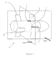
- a projectile 15 is composed of a body 10, stabilizing planes 11, control surfaces 3 and housing 1 for these control surfaces.
- the control surfaces 3 are deployed such as on the figure 1 and the slots 1 are empty. The larger the control surfaces 3 are, the more effective they are, but also the more cumbersome when they are folded within the projectile body 10.
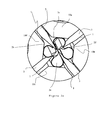
- the housing 1 are communicating at the axis 14 of the projectile in order to it is possible to use control surfaces 3 with a width L substantially equal to the radius R of the projectile body.
- the projectile 15 may be in incidence on trajectory.
- the flow of the air threads 12 is not perfectly parallel to the axis 14 of progression of the projectile 15 but with an angle ⁇ .
- the incidence shown here shows at the external surface of the body 10 a depression in the upper part of the projectile and an inlet of air threads 12 through the housing 1 of the control surfaces 3.
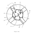
- a sealing device 2 is added as shown in FIGS. figures 3 and 4 .
- the sealing device 2 is formed of flexible tube section 2b, 2c, 2d and 2e may be polyethylene thickness of 0.5mm.
- Each section is integral with a sector of the projectile body 10a, 10b, 10c and 10d. These sectors are secured to the projectile body 10 by a mechanical means not shown.
- the tube sections are placed edge to edge with slight edge compression to form a lip facing the center of the projectile body. The lip thus formed must arrive in the same central plane as that of the rudder 3.
- the lip 20 will now prevent the flow of air streams from the inside to the outside of the body.
- the lip 20 may allow the end of the rudder to pass as illustrated by FIG. figure 3a while maintaining the sealing characteristic by contact between the tube sectors and the rudder on either side thereof.
- FIGS. 5a to 5c show a second embodiment in which the sealing means will be formed by a sliding door 16, at each rudder 3.
- this trapdoor will close the housing 1 in a sealed manner (using a seal for example) such as on the figure 5a .
- the hatch 16 actuated by a motor not shown, will slide on the side as on the figure 5b to clear the housing 1.
- the flap 16 will resume its initial position by sliding between the projectile body 10 and the rudder 3 thanks to the engine not shown.
Landscapes
- Physics & Mathematics (AREA)
- Fluid Mechanics (AREA)
- Engineering & Computer Science (AREA)
- General Engineering & Computer Science (AREA)
- Toys (AREA)
- Sealing Devices (AREA)
Abstract
Description
- Le domaine technique de l'invention est celui des projectiles dotés d'appendices déployables sur leur pourtour.
- La sophistication des projectiles actuels vise à les doter de nouvelles fonctions qui nécessitent le déploiement sur trajectoire de capteurs ou d'actionneurs à l'extérieur du corps du projectile. Dans un but de précision accrue, les projectiles sont par exemple dotés d'aérofreins ou de gouvernes déployables telles que retenues dans la suite du document à titre d'exemple.
- Les gouvernes utilisées pour orienter la trajectoire d'un projectile sont contenues dans le corps du projectile durant son transport et/ou durant sa première phase de vol. Chaque gouverne trouve sa place au sein du projectile grâce à un logement prévu à cet effet. Il est intéressant d'avoir des gouvernes les plus larges possibles afin d'optimiser leur influence sur la trajectoire une fois leur déploiement réalisé. Cependant, l'encombrement des gouvernes élargies génère un problème du fait de la profondeur limitée des logements pouvant accueillir les gouvernes.
- L'invention se propose de résoudre le problème encombrement des gouvernes en faisant communiquer les logements de gouvernes au niveau de leur intersection. L'emploi de cette solution occasionne cependant, lorsque les gouvernes sont déployées, des problèmes de perturbations aérodynamiques au niveau des gouvernes du fait de la circulation d'air ayant lieu dans les logements de gouvernes vides.
- Pour éviter la circulation d'air dans les logements de gouvernes, il est connu de
W02009/051866 un dispositif obturant la sortie des logements de gouvernes d'un projectile par des panneaux. Cependant ces panneaux sont éjectés avant le déploiement des gouvernes. Ils n'ont donc aucune efficacité lors du vol du projectile, lorsque le problème de perturbations aérodynamiques survient. - L'invention se propose donc de résoudre ce problème en interdisant le passage de l'air au travers des logements de gouvernes une fois les gouvernes sorties de leurs logements et ceci malgré les mouvements des gouvernes.
- L'invention vise donc un corps de projectile permettant la mise en place de gouvernes élargies tout en ne perturbant pas le comportement aérodynamique du projectile une fois les gouvernes déployées.
- L'invention a donc pour objet un corps de projectile destiné à évoluer dans un fluide, corps doté d'au moins deux gouvernes déployables radialement, gouvernes prenant place en attente de déploiement dans des logements pratiqués dans le corps, corps caractérisé en ce que les logements communiquent au niveau de leur intersection, chaque logement étant obturé par un moyen d'étanchéité interdisant la traversée des logements par le fluide extérieur au corps de projectile lorsque les gouvernes sont déployées.
- Suivant un mode de réalisation, le moyen d'étanchéité comporte pour chaque logement au moins une trappe obturant le logement au niveau de son extrémité débouchant du corps de projectile.
- Suivant un autre mode de réalisation, le moyen d'étanchéité comporte des secteurs de tube placés coaxialement au projectile à l'intersection des différents logements de gouvernes, secteurs de tube solidaires du corps de projectile et en contact entre eux deux par deux par au moins une génératrice quand la gouverne est déployée, génératrice de contact qui est placée dans le même plan que celui des gouvernes déployables, secteurs de tubes en contact avec les gouvernes déployables quand celle ci sont en position rentrées.
- L'orientation du moyen d'étanchéité empêchera la sortie du fluide au travers des logements.
- L'invention sera mieux comprise à la lecture de la description qui va suivre de modes particuliers de réalisation, description faite en référence aux dessins annexés et dans lesquels:
- La
figure 1 représente schématiquement le projectile en vue de trois quarts arrière avec les gouvernes et le jeu d'ailerons stabilisateurs arrière déployés. Elle localise les plans de coupe longitudinale A et transversale B. - La
figure 2 représente schématiquement suivant la coupe longitudinale A, le projectile en incidence. - La
figure 3 représente suivant la coupe transversale B le projectile, gouvernes dans leurs logements. - La
figure 3a représente une vue de détail agrandie du repère F de lafigure 3 . - La
figure 4 représente suivant la coupe transversale B le projectile gouvernes déployées. - La
figure 4a représente une vue de détail agrandie du repère G de lafigure 4 . - La
figure 5a représente, suivant un autre mode de réalisation, une vue de détail du corps de projectile au niveau d'une gouverne repliée dans son logement obturé par un dispositif d'étanchéité externe. - La
figure 5b représente une vue de détail du corps de projectile au niveau d'une gouverne dans son logement où le dispositif d'étanchéité externe s'est effacé sur un coté. - La
figure 5c représente une vue de détail du corps de projectile au niveau d'une gouverne sortie de son logement où le dispositif d'étanchéité externe est revenu obturer le logement. - En se reportant aux
figures 1 et2 , un projectile 15 est composé d'un corps 10, de plans stabilisateurs 11, de gouvernes 3 et de logements 1 pour ces gouvernes. En vol les gouvernes 3 sont déployées telles que sur lafigure 1 et les logements 1 sont donc vides. Plus les gouvernes 3 sont larges plus elles sont efficaces mais aussi plus elles sont encombrantes lorsqu'elles sont repliées au sein du corps de projectile 10. - Selon une première caractéristique de l'invention plus particulièrement visible à la
figure 3 , les logements 1 sont communicants au niveau de l'axe 14 du projectile afin de pouvoir employer des gouvernes 3 d'une largeur L sensiblement égale au rayon R du corps de projectile. - Tel qu'illustré par la
figure 2 le projectile 15 peut se trouver en incidence sur trajectoire. De ce fait l'écoulement des filets d'air 12 ne se fait pas parfaitement parallèlement à l'axe 14 de progression du projectile 15 mais avec un angle α. - L'incidence ici représentée fait apparaître au niveau de la surface externe du corps 10 une dépression en partie supérieure du projectile et une entrée de filets d'air 12 au travers des logements 1 des gouvernes 3.
- La sortie de ces filets d'air au niveau du logement de gouverne opposé risque de créer des turbulences 13 perturbant l'efficacité des gouvernes. Il est nécessaire de supprimer un tel écoulement.
- Afin de supprimer ces écoulements parasites, selon une seconde caractéristique de l'invention, on ajoute un dispositif d'étanchéité 2 tel que montré sur les
figures 3 et4 . - Selon un premier mode de réalisation apparaissant aux
figures 3 et4 dans les cercles pointillés F et G qui sont détaillés auxfigures 3a et4a , le dispositif d'étanchéité 2 est formé de section de tube souple 2b, 2c, 2d et 2e pouvant être du polyéthylène d'épaisseur 0,5mm. Chaque section est solidaire d'un secteur du corps de projectile 10a, 10b, 10c et 10d. Ces secteurs sont solidaires du corps de projectile 10 par un moyen mécanique non représenté. Les sections de tube sont placées bord à bord avec une légère compression des bords afin de former une lèvre 20 tournée vers le centre du corps de projectile. La lèvre ainsi formée doit arriver dans le même plan central que celui de la gouverne 3. La lèvre 20 va désormais empêcher l'écoulement des filets d'air de l'intérieur vers l'extérieur du corps. - Gouvernes 3 en positions rentrées, la lèvre 20 pourra laisser passer l'extrémité de la gouverne comme l'illustre la
figure 3a tout en conservant la caractéristique d'étanchéité par contact entre les secteurs de tube et la gouverne de part et d'autre de celle ci. - Les
figures 5a à 5c montrent un second mode de réalisation dans lequel le moyen d'étanchéité sera formé par une trappe 16 coulissante, au niveau de chaque gouverne 3. - En position gouverne 3 rentrée, cette trappe va obturer le logement 1 de façon étanche (à l'aide d'un joint par exemple) tel que sur la
figure 5a . - Avant le déploiement de la gouverne 3, la trappe 16, actionnée par un moteur non représenté, va coulisser sur le coté tel que sur la
figure 5b pour dégager le logement 1. - Comme illustré sur la
figure 5c , une fois la gouverne 3 déployée, la trappe 16 va reprendre sa position initiale en coulissant entre le corps de projectile 10 et la gouverne 3 grâce au moteur non représenté. - De cette manière aucun filet d'air ne viendra perturber le fonctionnement des gouvernes.
Claims (4)
- Corps (10) de projectile destiné à évoluer dans un fluide, corps doté d'au moins deux gouvernes (3) déployables radialement, gouvernes (3) prenant place en attente de déploiement dans des logements (1) pratiqués dans le corps (10), corps (10) caractérisé en ce que les logements (1) communiquent au niveau de leur intersection, chaque logement (1) étant obturé par un moyen d'étanchéité (2, 15) interdisant la traversée des logements (1) par le fluide extérieur au corps (10) de projectile lorsque les gouvernes sont déployées.
- Corps (10) de projectile selon la revendication 1 caractérisé en ce que le moyen d'étanchéité comporte pour chaque logement au moins une trappe (15) obturant le logement (1) au niveau de son extrémité débouchant du corps (10) de projectile.
- Corps de projectile (10) selon la revendication 1 caractérisé en ce que le moyen d'étanchéité (2) comporte des secteurs de tube (2b,c,d,e) placés coaxialement au projectile à l'intersection des différents logements (1) de gouvernes (3), secteurs (2) de tube solidaires du corps de projectile et en contact entre eux deux par deux par au moins une génératrice quand la gouverne (3) est déployée, génératrice de contact qui est placée dans le même plan que celui des gouvernes (3) déployables, secteurs de tubes en contact avec les gouvernes (3) déployables quand celles ci sont en position rentrées.
- Corps de projectile (10) selon la revendication 3 caractérisé en ce que l'orientation du moyen d'étanchéité (2) empêche la sortie du fluide au travers des logements (1).
Priority Applications (1)
| Application Number | Priority Date | Filing Date | Title |
|---|---|---|---|
| PL10290609T PL2322895T3 (pl) | 2009-11-16 | 2010-11-15 | Korpus pocisku wyposażony w rozkładane powierzchnie sterowe |
Applications Claiming Priority (1)
| Application Number | Priority Date | Filing Date | Title |
|---|---|---|---|
| FR0905494A FR2952712A1 (fr) | 2009-11-16 | 2009-11-16 | Corps de projectile equipe d'appendices deployables |
Publications (2)
| Publication Number | Publication Date |
|---|---|
| EP2322895A1 true EP2322895A1 (fr) | 2011-05-18 |
| EP2322895B1 EP2322895B1 (fr) | 2014-01-08 |
Family
ID=42227638
Family Applications (1)
| Application Number | Title | Priority Date | Filing Date |
|---|---|---|---|
| EP10290609.6A Active EP2322895B1 (fr) | 2009-11-16 | 2010-11-15 | Corps de projectile équipé de gouvernes déployables |
Country Status (5)
| Country | Link |
|---|---|
| US (1) | US8450669B2 (fr) |
| EP (1) | EP2322895B1 (fr) |
| ES (1) | ES2448390T3 (fr) |
| FR (1) | FR2952712A1 (fr) |
| PL (1) | PL2322895T3 (fr) |
Families Citing this family (1)
| Publication number | Priority date | Publication date | Assignee | Title |
|---|---|---|---|---|
| FR3089620B1 (fr) | 2018-12-11 | 2022-04-01 | Nexter Munitions | Projectile a plans de voilure deployables |
Citations (4)
| Publication number | Priority date | Publication date | Assignee | Title |
|---|---|---|---|---|
| DE3432614A1 (de) * | 1984-09-05 | 1986-03-13 | Rheinmetall GmbH, 4000 Düsseldorf | Flugkoerper |
| US4869442A (en) * | 1988-09-02 | 1989-09-26 | Aerojet-General Corporation | Self-deploying airfoil |
| WO2001079779A1 (fr) * | 2000-03-21 | 2001-10-25 | Bofors Defence Ab | Obus d'artillerie stabilise par des ailettes |
| WO2009051866A1 (fr) | 2007-10-19 | 2009-04-23 | Hr Textron Inc. | Techniques pour contrôler l'accès à travers une fente sur un projectile |
Family Cites Families (2)
| Publication number | Priority date | Publication date | Assignee | Title |
|---|---|---|---|---|
| US3853288A (en) * | 1967-07-17 | 1974-12-10 | H Bode | Encasement for the tail section of a rocket with a central nozzle and extendible control vanes |
| US6260797B1 (en) * | 1998-01-13 | 2001-07-17 | Science Applications International Corporation | Transformable gun launched aero vehicle |
-
2009
- 2009-11-16 FR FR0905494A patent/FR2952712A1/fr not_active Withdrawn
-
2010
- 2010-11-10 US US12/943,472 patent/US8450669B2/en active Active
- 2010-11-15 ES ES10290609.6T patent/ES2448390T3/es active Active
- 2010-11-15 EP EP10290609.6A patent/EP2322895B1/fr active Active
- 2010-11-15 PL PL10290609T patent/PL2322895T3/pl unknown
Patent Citations (4)
| Publication number | Priority date | Publication date | Assignee | Title |
|---|---|---|---|---|
| DE3432614A1 (de) * | 1984-09-05 | 1986-03-13 | Rheinmetall GmbH, 4000 Düsseldorf | Flugkoerper |
| US4869442A (en) * | 1988-09-02 | 1989-09-26 | Aerojet-General Corporation | Self-deploying airfoil |
| WO2001079779A1 (fr) * | 2000-03-21 | 2001-10-25 | Bofors Defence Ab | Obus d'artillerie stabilise par des ailettes |
| WO2009051866A1 (fr) | 2007-10-19 | 2009-04-23 | Hr Textron Inc. | Techniques pour contrôler l'accès à travers une fente sur un projectile |
Also Published As
| Publication number | Publication date |
|---|---|
| EP2322895B1 (fr) | 2014-01-08 |
| FR2952712A1 (fr) | 2011-05-20 |
| PL2322895T3 (pl) | 2014-06-30 |
| US20110114783A1 (en) | 2011-05-19 |
| US8450669B2 (en) | 2013-05-28 |
| ES2448390T3 (es) | 2014-03-13 |
Similar Documents
| Publication | Publication Date | Title |
|---|---|---|
| CA2606948C (fr) | Nageoire de plateforme de soufflante | |
| EP2091768B1 (fr) | Aérateur à réglage d 'orientation et de débit d'un flux d'air | |
| CA2204589C (fr) | Inverseur de poussee de turboreacteur a portes munies d'aubes deflectrices | |
| WO1998026172A1 (fr) | Inverseur de poussee de turboreacteur a portes comportant des aubes deflectrices associees a la structure fixe | |
| EP2955112A1 (fr) | Nacelle d'aeronef comprenant une entree d'air | |
| EP3377394B1 (fr) | Deflecteur actif | |
| FR3036382A1 (fr) | Nacelle d'aeronef comportant au moins un capot monte rotatif autour de l'axe longitudinal de la nacelle | |
| FR2901321A1 (fr) | Procede d'homogeneisation de l'air en sortie de turboreacteur pour abaisser le bruit genere | |
| EP4045397B1 (fr) | Ensemble pour turbomachine | |
| CA2931310A1 (fr) | Dispositif de retention de fluides draines pour un ensemble propulsif | |
| FR2994560A1 (fr) | Dispositif permettant de remorquer un engin sous-marin autonome | |
| EP2853834B1 (fr) | Dispositif de régulation du débit d'air dans une canalisation | |
| EP2322895B1 (fr) | Corps de projectile équipé de gouvernes déployables | |
| EP3719374A1 (fr) | Dispositif joint tournant configure pour equiper une installation d'exploitation de fluides, notamment sur une plateforme offshore | |
| CA2489717C (fr) | Drain notamment pour mat support de reacteur | |
| EP3587784A1 (fr) | Turboreacteur comportant une nacelle equipee de volets inverseurs pourvus de moyens pour generer des tourbillons | |
| WO2018078259A1 (fr) | Module de face avant pour vehicule automobile | |
| EP3411256B1 (fr) | Dispositif d'obturation d'entrée d'air de face avant de véhicule automobile | |
| FR3024495B1 (fr) | Dispositif de circulation d'air a debit ajustable pour turbomachine | |
| CH711721B1 (fr) | Carénage hypersustentateur à géométrie variable ou/et orientable pour systèmes propulsifs. | |
| WO2015114241A1 (fr) | Nacelle pour turboréacteur d'avion | |
| FR2886892A1 (fr) | Dispositif d'alimentation en air d'un moteur de vehicule | |
| FR3068080B1 (fr) | Nacelle d'aeronef comportant un volet inverseur et un joint | |
| EP3563047B1 (fr) | Moyeu de carter intermédiaire comprenant des canaux de guidage du flux de décharge formés par les ailettes de décharge | |
| FR3105366A1 (fr) | Dispositif de ventilation pour module de refroidissement de véhicule automobile et module de refroidissement pour véhicule automobile comprenant un tel dispositif de ventilation |
Legal Events
| Date | Code | Title | Description |
|---|---|---|---|
| PUAI | Public reference made under article 153(3) epc to a published international application that has entered the european phase |
Free format text: ORIGINAL CODE: 0009012 |
|
| AK | Designated contracting states |
Kind code of ref document: A1 Designated state(s): AL AT BE BG CH CY CZ DE DK EE ES FI FR GB GR HR HU IE IS IT LI LT LU LV MC MK MT NL NO PL PT RO RS SE SI SK SM TR |
|
| AX | Request for extension of the european patent |
Extension state: BA ME |
|
| 17P | Request for examination filed |
Effective date: 20111118 |
|
| GRAP | Despatch of communication of intention to grant a patent |
Free format text: ORIGINAL CODE: EPIDOSNIGR1 |
|
| INTG | Intention to grant announced |
Effective date: 20130722 |
|
| GRAS | Grant fee paid |
Free format text: ORIGINAL CODE: EPIDOSNIGR3 |
|
| GRAA | (expected) grant |
Free format text: ORIGINAL CODE: 0009210 |
|
| AK | Designated contracting states |
Kind code of ref document: B1 Designated state(s): AL AT BE BG CH CY CZ DE DK EE ES FI FR GB GR HR HU IE IS IT LI LT LU LV MC MK MT NL NO PL PT RO RS SE SI SK SM TR |
|
| REG | Reference to a national code |
Ref country code: GB Ref legal event code: FG4D Free format text: NOT ENGLISH |
|
| REG | Reference to a national code |
Ref country code: CH Ref legal event code: EP |
|
| REG | Reference to a national code |
Ref country code: IE Ref legal event code: FG4D Free format text: LANGUAGE OF EP DOCUMENT: FRENCH |
|
| REG | Reference to a national code |
Ref country code: AT Ref legal event code: REF Ref document number: 648999 Country of ref document: AT Kind code of ref document: T Effective date: 20140215 |
|
| REG | Reference to a national code |
Ref country code: DE Ref legal event code: R096 Ref document number: 602010012943 Country of ref document: DE Effective date: 20140220 |
|
| REG | Reference to a national code |
Ref country code: ES Ref legal event code: FG2A Ref document number: 2448390 Country of ref document: ES Kind code of ref document: T3 Effective date: 20140313 |
|
| REG | Reference to a national code |
Ref country code: SE Ref legal event code: TRGR |
|
| REG | Reference to a national code |
Ref country code: AT Ref legal event code: MK05 Ref document number: 648999 Country of ref document: AT Kind code of ref document: T Effective date: 20140108 |
|
| REG | Reference to a national code |
Ref country code: NL Ref legal event code: VDEP Effective date: 20140108 |
|
| REG | Reference to a national code |
Ref country code: NO Ref legal event code: T2 Effective date: 20140108 |
|
| REG | Reference to a national code |
Ref country code: LT Ref legal event code: MG4D |
|
| REG | Reference to a national code |
Ref country code: PL Ref legal event code: T3 |
|
| PG25 | Lapsed in a contracting state [announced via postgrant information from national office to epo] |
Ref country code: IS Free format text: LAPSE BECAUSE OF FAILURE TO SUBMIT A TRANSLATION OF THE DESCRIPTION OR TO PAY THE FEE WITHIN THE PRESCRIBED TIME-LIMIT Effective date: 20140508 Ref country code: LT Free format text: LAPSE BECAUSE OF FAILURE TO SUBMIT A TRANSLATION OF THE DESCRIPTION OR TO PAY THE FEE WITHIN THE PRESCRIBED TIME-LIMIT Effective date: 20140108 |
|
| PG25 | Lapsed in a contracting state [announced via postgrant information from national office to epo] |
Ref country code: CY Free format text: LAPSE BECAUSE OF FAILURE TO SUBMIT A TRANSLATION OF THE DESCRIPTION OR TO PAY THE FEE WITHIN THE PRESCRIBED TIME-LIMIT Effective date: 20140108 Ref country code: FI Free format text: LAPSE BECAUSE OF FAILURE TO SUBMIT A TRANSLATION OF THE DESCRIPTION OR TO PAY THE FEE WITHIN THE PRESCRIBED TIME-LIMIT Effective date: 20140108 Ref country code: PT Free format text: LAPSE BECAUSE OF FAILURE TO SUBMIT A TRANSLATION OF THE DESCRIPTION OR TO PAY THE FEE WITHIN THE PRESCRIBED TIME-LIMIT Effective date: 20140508 Ref country code: AT Free format text: LAPSE BECAUSE OF FAILURE TO SUBMIT A TRANSLATION OF THE DESCRIPTION OR TO PAY THE FEE WITHIN THE PRESCRIBED TIME-LIMIT Effective date: 20140108 Ref country code: NL Free format text: LAPSE BECAUSE OF FAILURE TO SUBMIT A TRANSLATION OF THE DESCRIPTION OR TO PAY THE FEE WITHIN THE PRESCRIBED TIME-LIMIT Effective date: 20140108 |
|
| PG25 | Lapsed in a contracting state [announced via postgrant information from national office to epo] |
Ref country code: RS Free format text: LAPSE BECAUSE OF FAILURE TO SUBMIT A TRANSLATION OF THE DESCRIPTION OR TO PAY THE FEE WITHIN THE PRESCRIBED TIME-LIMIT Effective date: 20140108 Ref country code: LV Free format text: LAPSE BECAUSE OF FAILURE TO SUBMIT A TRANSLATION OF THE DESCRIPTION OR TO PAY THE FEE WITHIN THE PRESCRIBED TIME-LIMIT Effective date: 20140108 Ref country code: HR Free format text: LAPSE BECAUSE OF FAILURE TO SUBMIT A TRANSLATION OF THE DESCRIPTION OR TO PAY THE FEE WITHIN THE PRESCRIBED TIME-LIMIT Effective date: 20140108 |
|
| REG | Reference to a national code |
Ref country code: DE Ref legal event code: R097 Ref document number: 602010012943 Country of ref document: DE |
|
| PG25 | Lapsed in a contracting state [announced via postgrant information from national office to epo] |
Ref country code: EE Free format text: LAPSE BECAUSE OF FAILURE TO SUBMIT A TRANSLATION OF THE DESCRIPTION OR TO PAY THE FEE WITHIN THE PRESCRIBED TIME-LIMIT Effective date: 20140108 Ref country code: DK Free format text: LAPSE BECAUSE OF FAILURE TO SUBMIT A TRANSLATION OF THE DESCRIPTION OR TO PAY THE FEE WITHIN THE PRESCRIBED TIME-LIMIT Effective date: 20140108 Ref country code: CZ Free format text: LAPSE BECAUSE OF FAILURE TO SUBMIT A TRANSLATION OF THE DESCRIPTION OR TO PAY THE FEE WITHIN THE PRESCRIBED TIME-LIMIT Effective date: 20140108 Ref country code: RO Free format text: LAPSE BECAUSE OF FAILURE TO SUBMIT A TRANSLATION OF THE DESCRIPTION OR TO PAY THE FEE WITHIN THE PRESCRIBED TIME-LIMIT Effective date: 20140108 |
|
| PLBE | No opposition filed within time limit |
Free format text: ORIGINAL CODE: 0009261 |
|
| STAA | Information on the status of an ep patent application or granted ep patent |
Free format text: STATUS: NO OPPOSITION FILED WITHIN TIME LIMIT |
|
| PG25 | Lapsed in a contracting state [announced via postgrant information from national office to epo] |
Ref country code: SK Free format text: LAPSE BECAUSE OF FAILURE TO SUBMIT A TRANSLATION OF THE DESCRIPTION OR TO PAY THE FEE WITHIN THE PRESCRIBED TIME-LIMIT Effective date: 20140108 |
|
| 26N | No opposition filed |
Effective date: 20141009 |
|
| REG | Reference to a national code |
Ref country code: DE Ref legal event code: R097 Ref document number: 602010012943 Country of ref document: DE Effective date: 20141009 |
|
| PG25 | Lapsed in a contracting state [announced via postgrant information from national office to epo] |
Ref country code: SI Free format text: LAPSE BECAUSE OF FAILURE TO SUBMIT A TRANSLATION OF THE DESCRIPTION OR TO PAY THE FEE WITHIN THE PRESCRIBED TIME-LIMIT Effective date: 20140108 |
|
| PG25 | Lapsed in a contracting state [announced via postgrant information from national office to epo] |
Ref country code: MC Free format text: LAPSE BECAUSE OF FAILURE TO SUBMIT A TRANSLATION OF THE DESCRIPTION OR TO PAY THE FEE WITHIN THE PRESCRIBED TIME-LIMIT Effective date: 20140108 Ref country code: LU Free format text: LAPSE BECAUSE OF FAILURE TO SUBMIT A TRANSLATION OF THE DESCRIPTION OR TO PAY THE FEE WITHIN THE PRESCRIBED TIME-LIMIT Effective date: 20141115 |
|
| REG | Reference to a national code |
Ref country code: CH Ref legal event code: PL |
|
| PG25 | Lapsed in a contracting state [announced via postgrant information from national office to epo] |
Ref country code: LI Free format text: LAPSE BECAUSE OF NON-PAYMENT OF DUE FEES Effective date: 20141130 Ref country code: CH Free format text: LAPSE BECAUSE OF NON-PAYMENT OF DUE FEES Effective date: 20141130 |
|
| REG | Reference to a national code |
Ref country code: IE Ref legal event code: MM4A |
|
| REG | Reference to a national code |
Ref country code: FR Ref legal event code: PLFP Year of fee payment: 6 |
|
| PG25 | Lapsed in a contracting state [announced via postgrant information from national office to epo] |
Ref country code: IE Free format text: LAPSE BECAUSE OF NON-PAYMENT OF DUE FEES Effective date: 20141115 |
|
| PG25 | Lapsed in a contracting state [announced via postgrant information from national office to epo] |
Ref country code: SM Free format text: LAPSE BECAUSE OF FAILURE TO SUBMIT A TRANSLATION OF THE DESCRIPTION OR TO PAY THE FEE WITHIN THE PRESCRIBED TIME-LIMIT Effective date: 20140108 |
|
| PG25 | Lapsed in a contracting state [announced via postgrant information from national office to epo] |
Ref country code: GR Free format text: LAPSE BECAUSE OF FAILURE TO SUBMIT A TRANSLATION OF THE DESCRIPTION OR TO PAY THE FEE WITHIN THE PRESCRIBED TIME-LIMIT Effective date: 20140409 Ref country code: BG Free format text: LAPSE BECAUSE OF FAILURE TO SUBMIT A TRANSLATION OF THE DESCRIPTION OR TO PAY THE FEE WITHIN THE PRESCRIBED TIME-LIMIT Effective date: 20140108 |
|
| PG25 | Lapsed in a contracting state [announced via postgrant information from national office to epo] |
Ref country code: MT Free format text: LAPSE BECAUSE OF FAILURE TO SUBMIT A TRANSLATION OF THE DESCRIPTION OR TO PAY THE FEE WITHIN THE PRESCRIBED TIME-LIMIT Effective date: 20140108 Ref country code: TR Free format text: LAPSE BECAUSE OF FAILURE TO SUBMIT A TRANSLATION OF THE DESCRIPTION OR TO PAY THE FEE WITHIN THE PRESCRIBED TIME-LIMIT Effective date: 20140108 Ref country code: HU Free format text: LAPSE BECAUSE OF FAILURE TO SUBMIT A TRANSLATION OF THE DESCRIPTION OR TO PAY THE FEE WITHIN THE PRESCRIBED TIME-LIMIT; INVALID AB INITIO Effective date: 20101115 |
|
| REG | Reference to a national code |
Ref country code: FR Ref legal event code: PLFP Year of fee payment: 7 |
|
| REG | Reference to a national code |
Ref country code: FR Ref legal event code: PLFP Year of fee payment: 8 |
|
| PG25 | Lapsed in a contracting state [announced via postgrant information from national office to epo] |
Ref country code: MK Free format text: LAPSE BECAUSE OF FAILURE TO SUBMIT A TRANSLATION OF THE DESCRIPTION OR TO PAY THE FEE WITHIN THE PRESCRIBED TIME-LIMIT Effective date: 20140108 |
|
| REG | Reference to a national code |
Ref country code: FR Ref legal event code: PLFP Year of fee payment: 9 |
|
| PG25 | Lapsed in a contracting state [announced via postgrant information from national office to epo] |
Ref country code: AL Free format text: LAPSE BECAUSE OF FAILURE TO SUBMIT A TRANSLATION OF THE DESCRIPTION OR TO PAY THE FEE WITHIN THE PRESCRIBED TIME-LIMIT Effective date: 20140108 |
|
| PGFP | Annual fee paid to national office [announced via postgrant information from national office to epo] |
Ref country code: ES Payment date: 20211201 Year of fee payment: 12 |
|
| PGFP | Annual fee paid to national office [announced via postgrant information from national office to epo] |
Ref country code: BE Payment date: 20211020 Year of fee payment: 12 |
|
| PGFP | Annual fee paid to national office [announced via postgrant information from national office to epo] |
Ref country code: PL Payment date: 20211021 Year of fee payment: 12 |
|
| REG | Reference to a national code |
Ref country code: BE Ref legal event code: MM Effective date: 20221130 |
|
| PG25 | Lapsed in a contracting state [announced via postgrant information from national office to epo] |
Ref country code: BE Free format text: LAPSE BECAUSE OF NON-PAYMENT OF DUE FEES Effective date: 20221130 |
|
| REG | Reference to a national code |
Ref country code: ES Ref legal event code: FD2A Effective date: 20240102 |
|
| PG25 | Lapsed in a contracting state [announced via postgrant information from national office to epo] |
Ref country code: ES Free format text: LAPSE BECAUSE OF NON-PAYMENT OF DUE FEES Effective date: 20221116 |
|
| PG25 | Lapsed in a contracting state [announced via postgrant information from national office to epo] |
Ref country code: ES Free format text: LAPSE BECAUSE OF NON-PAYMENT OF DUE FEES Effective date: 20221116 |
|
| PG25 | Lapsed in a contracting state [announced via postgrant information from national office to epo] |
Ref country code: PL Free format text: LAPSE BECAUSE OF NON-PAYMENT OF DUE FEES Effective date: 20221115 |
|
| PGFP | Annual fee paid to national office [announced via postgrant information from national office to epo] |
Ref country code: DE Payment date: 20251022 Year of fee payment: 16 |
|
| PGFP | Annual fee paid to national office [announced via postgrant information from national office to epo] |
Ref country code: GB Payment date: 20251023 Year of fee payment: 16 |
|
| PGFP | Annual fee paid to national office [announced via postgrant information from national office to epo] |
Ref country code: NO Payment date: 20251024 Year of fee payment: 16 |
|
| PGFP | Annual fee paid to national office [announced via postgrant information from national office to epo] |
Ref country code: IT Payment date: 20251022 Year of fee payment: 16 |
|
| PGFP | Annual fee paid to national office [announced via postgrant information from national office to epo] |
Ref country code: FR Payment date: 20251022 Year of fee payment: 16 |
|
| PGFP | Annual fee paid to national office [announced via postgrant information from national office to epo] |
Ref country code: SE Payment date: 20251022 Year of fee payment: 16 |