EP2322815A2 - Blind rivet - Google Patents
Blind rivet Download PDFInfo
- Publication number
- EP2322815A2 EP2322815A2 EP10190613A EP10190613A EP2322815A2 EP 2322815 A2 EP2322815 A2 EP 2322815A2 EP 10190613 A EP10190613 A EP 10190613A EP 10190613 A EP10190613 A EP 10190613A EP 2322815 A2 EP2322815 A2 EP 2322815A2
- Authority
- EP
- European Patent Office
- Prior art keywords
- head
- rivet
- viewed
- sleeve
- tip
- Prior art date
- Legal status (The legal status is an assumption and is not a legal conclusion. Google has not performed a legal analysis and makes no representation as to the accuracy of the status listed.)
- Granted
Links
- 230000002093 peripheral effect Effects 0.000 claims description 3
- 230000004323 axial length Effects 0.000 description 10
- 230000006866 deterioration Effects 0.000 description 3
- 238000003754 machining Methods 0.000 description 3
- XEEYBQQBJWHFJM-UHFFFAOYSA-N Iron Chemical compound [Fe] XEEYBQQBJWHFJM-UHFFFAOYSA-N 0.000 description 2
- 239000000463 material Substances 0.000 description 2
- 239000007769 metal material Substances 0.000 description 2
- 229910052782 aluminium Inorganic materials 0.000 description 1
- XAGFODPZIPBFFR-UHFFFAOYSA-N aluminium Chemical compound [Al] XAGFODPZIPBFFR-UHFFFAOYSA-N 0.000 description 1
- 238000013459 approach Methods 0.000 description 1
- 230000005484 gravity Effects 0.000 description 1
- 229910052742 iron Inorganic materials 0.000 description 1
- 238000000034 method Methods 0.000 description 1
- 229910001220 stainless steel Inorganic materials 0.000 description 1
- 239000010935 stainless steel Substances 0.000 description 1
- 230000002459 sustained effect Effects 0.000 description 1
Images


Classifications
-
- F—MECHANICAL ENGINEERING; LIGHTING; HEATING; WEAPONS; BLASTING
- F16—ENGINEERING ELEMENTS AND UNITS; GENERAL MEASURES FOR PRODUCING AND MAINTAINING EFFECTIVE FUNCTIONING OF MACHINES OR INSTALLATIONS; THERMAL INSULATION IN GENERAL
- F16B—DEVICES FOR FASTENING OR SECURING CONSTRUCTIONAL ELEMENTS OR MACHINE PARTS TOGETHER, e.g. NAILS, BOLTS, CIRCLIPS, CLAMPS, CLIPS OR WEDGES; JOINTS OR JOINTING
- F16B19/00—Bolts without screw-thread; Pins, including deformable elements; Rivets
- F16B19/04—Rivets; Spigots or the like fastened by riveting
- F16B19/08—Hollow rivets; Multi-part rivets
- F16B19/10—Hollow rivets; Multi-part rivets fastened by expanding mechanically
- F16B19/1027—Multi-part rivets
- F16B19/1036—Blind rivets
- F16B19/1045—Blind rivets fastened by a pull - mandrel or the like
- F16B19/1054—Blind rivets fastened by a pull - mandrel or the like the pull-mandrel or the like being frangible
-
- F—MECHANICAL ENGINEERING; LIGHTING; HEATING; WEAPONS; BLASTING
- F16—ENGINEERING ELEMENTS AND UNITS; GENERAL MEASURES FOR PRODUCING AND MAINTAINING EFFECTIVE FUNCTIONING OF MACHINES OR INSTALLATIONS; THERMAL INSULATION IN GENERAL
- F16B—DEVICES FOR FASTENING OR SECURING CONSTRUCTIONAL ELEMENTS OR MACHINE PARTS TOGETHER, e.g. NAILS, BOLTS, CIRCLIPS, CLAMPS, CLIPS OR WEDGES; JOINTS OR JOINTING
- F16B19/00—Bolts without screw-thread; Pins, including deformable elements; Rivets
- F16B19/04—Rivets; Spigots or the like fastened by riveting
- F16B19/08—Hollow rivets; Multi-part rivets
- F16B19/10—Hollow rivets; Multi-part rivets fastened by expanding mechanically
- F16B19/1027—Multi-part rivets
- F16B19/1036—Blind rivets
- F16B19/1045—Blind rivets fastened by a pull - mandrel or the like
Definitions
- the present invention relates to a blind rivet and, more specifically, to a blind rivet able to keep the broken mandrel portion attached to the rivet from dropping off the rivet body after fastening.
- a blind rivet comprises a rivet body consisting of a hollow sleeve and a hollow flange formed at one end of the sleeve with a larger diameter than the sleeve, and a mandrel consisting of a shaft portion extending from the flange through the rivet body and a head integrally connected to the shaft portion with a diameter greater than the inner diameter of the sleeve arranged adjacent to the sleeve end on the side opposite that of the flange.
- the rivet body with the mandrel passing though is inserted with the mandrel head in front into the attachment hole of the attached component aligned with the attachment hole of the attached member.
- the mandrel shaft extending from the flange on the attached component side is forcibly drawn out by the operation of the fastening tool until it breaks off.
- the forcible drawing of the mandrel shaft causes the mandrel head to pull the sleeve portion on the rear surface of the attached member towards the flange side.
- a portion of the sleeve expands outward radially and is deformed.
- the attached member and the attached component are interposed between the flange and the expanded and deformed portion of the sleeve, and the attached member and the attached component are fastened by the blind rivet. This fastening operation joins the attached component to the attached member.
- the mandrel shaft portion of the broken mandrel held by the fastening tool is accommodated in the fastening tool in order to expand and deform the sleeve, this portion can be discarded from the fastening tool at a location away from the attached member at the end of the fastening operation.
- the broken shaft portion of the mandrel remains with the head on the rivet body connected to the attached member. Because the mandrel portion is not connected to the rivet body, gravity often causes it to drop off the rivet body. The mandrel shaft portion attached to the dropped off mandrel loses motion on the rear surface of the attached member, making noise and sometimes damaging the rear surface of the attached member. Therefore, the mandrel portion attached to the broken off rivet should be kept from dropping off the rivet body.
- the broken off mandrel portion attached to the head has a head with a shape that keeps it from dropping off the rivet body.
- the mandrel head has a shape with a nearly round horizontal cross-section in the root portion adjacent to the mandrel shaft and an oval-shaped horizontal cross-section in the tip portion. The end of the sleeve on the rivet body expanded and deformed by the mandrel head is first expanded and deformed into a round shape by the head portion which has a round horizontal cross-section.
- the attached member and the attached component are interposed between the flange and the expanded and deformed portion of the sleeve, and the attached member and the attached component are fastened by the blind rivet.
- This fastening operation joins the attached component to the attached member.
- the strength of the expanded and deformed portion of the sleeve is weakened, the fastening strength of the blind rivet is reduced. As a result, the joining strength of the attached member and the attached component is also reduced.
- the object of the present invention is to provide a blind rivet that can keep the broken mandrel portion from dropping off the rivet body and that can maintain high fastening strength for the blind rivet.
- the present invention is a blind rivet comprising a rivet body consisting of a hollow sleeve and a hollow flange formed at one end of the sleeve with a larger diameter than the sleeve, and a mandrel consisting of a shaft portion extending from the flange through the rivet body and a head integrally connected to the shaft portion with a diameter greater than the inner diameter of the sleeve arranged adjacent to the sleeve end on the side opposite that of the flange, an attached member and an attached component being fastened and joined together by expanding a portion of the sleeve on the rivet body passed through attachment holes in the attached member and the attached component, and interposing the attached member and the attached component between the expanded portion and the flange.
- the blind rivet of the present invention is characterized in that the head has a maximum diameter portion as viewed from the front formed in the root portion adjacent to the shaft portion, a maximum diameter portion as viewed from the side in a direction perpendicular to the view from the front formed on the side of the tip of the rivet, the maximum diameter portion as viewed from the front being formed in a different location axially than the maximum diameter portion as viewed from the side with the axis of the rivet being arranged vertically and the tip of the rivet facing downward, and in that the horizontal cross-section of the head has a first ellipse formed in the maximum diameter portion as viewed from the front, and a second ellipse formed in the maximum diameter portion as viewed from the side with the long axis thereof perpendicular to the long axis of the first ellipse, the horizontal cross-sectional shape of the head gradually changing in the axial direction so as to continue from the first ellipse to the second ellipse, each one of the horizontal cross-sections having
- the head has a maximum diameter portion as viewed from the front formed in the root portion adjacent to the shaft portion, and a maximum diameter portion as viewed from the side in a direction perpendicular to the view from the front formed on the side of the tip of the rivet.
- FIG 1 through FIG 4 show the blind rivet 1 in the first embodiment, the blind rivet 1 after being fastened, the head of the mandrel and the shaft portion of the mandrel adjacent to the head in the blind rivet 1 of the first embodiment, and how the horizontal cross-sectional shapes and the circumferential lengths change along the axial length of the mandrel head.
- FIG 5 and FIG 6 show the head of the mandrel and the shaft portion of the mandrel adjacent to the head in the blind rivet of the second embodiment, and how the horizontal cross-sectional shapes and the circumferential lengths change along the axial length of the mandrel head.
- FIG 7 shows the head of the mandrel and the shaft portion of the mandrel adjacent to the head in the blind rivet of the third embodiment.
- FIG 8 shows the blind rivet in the fourth embodiment.
- the rivet body 5 and the mandrel 9 are integrally formed of a metal material that is the same as that of conventional blind rivets.
- metal materials that can be used to form the mandrel 9 and the rivet body 5 include iron, stainless steel and aluminum.
- FIG 2 shows the attached component 13 joined with the attached member 11 by the fastening of the blind rivet 1.
- the shaft portion 6 of the mandrel 9 extending from the flange 3 of the rivet body 5 is inserted by the operator and held in the nose of the fastening tool (not shown).
- the rivet body 5 with the mandrel 9 passing though is inserted with the mandrel head 7 in front into the attachment hole of the attached component 13 aligned with the attachment hole of the attached member 11.
- the head 7 of the mandrel 9 sticks out of the rear surface of the attached member 11 and the flange 3 on the rivet body 5 comes into contact with the attached component 13.
- the operator operates the fastening tool and the shaft portion 6 of the mandrel 9 extending from the flange 3 on the side with the attached component 13 is drawn against the flange 3 until it breaks in the breakable portion 10.
- the head 7 of the mandrel 9 is pressed strongly against the end of the sleeve 2
- the head 7 is pulled into the portion of the sleeve 2 on the rear surface side of the attached component 11, and a portion of the sleeve 2 (i.e., the portion at the end of the sleeve 2 adjacent to the mandrel head 7) is deformed so as to expand radially, forming the expanded and deformed portion 14 shown in FIG 2 .
- the attached member 11 making contact with the expanded and deformed portion 14 and the attached component 13 making contact with the flange 3 are firmly interposed working with the flange 3.
- the blind rivet 1 as shown in FIG 2 , interposes the attached member 11 and the attached component 13 between the expanded and deformed portion 14 of the sleeve 2 and the flange 3, the attached member 11 and the attached component 13 are fastened, and the attached member 11 and the attached component 13 are joined by the fastening operation.
- the blind rivet 1 has a head 7 with a shape that keeps the broken mandrel portion with the head attached from dropping off the rivet body 5. See FIG 3 .
- the head 7 is aligned in the axial direction (vertically in the figure) with the root portion, or the boundary portion 22 with the shaft portion 6.
- a pair of shoulders 17 is formed in the head 7 at the boundary portion 22 with the shaft portion 6 (i.e., in the root portion) diametrically facing the plane perpendicular to the axis 15 of the head 7 extending upward (i.e., the mandrel 9 including the shaft portion 6).
- the head 7 is aligned in the axial direction (vertically in the figure) with respect to the boundary portion 22 with the shaft portion 6 in FIGS 3 (A) and (B)
- the shoulders 17 in FIGS 3 (A) and (B) are shown at the same axial height.
- the head 7 can be obtained by machining a round rod with a diameter corresponding to the diameter of the shoulders 17 into the predetermined shape [see FIG 3 (D) ].
- the diameter of the head 7 is reduced (constricted) from the shoulders 17 towards the bottom end (i.e., the tip) with the tip of the head 7 extending vertically along the axis 15 of the head 7 facing downward.
- the head has a trapezoidal shape with a diameter shorter at the upper end (which substantially the same as the shaft portion 6) and a diameter longer at the tip or lower end (which is substantially the same as the portion with the shoulders 17).
- the shape as viewed from the bottom end (tip) is nearly as round as a round rod.
- the maximum diameter portion 19 in the side view [ FIG 3 (B) ] has substantially the same diameter as the maximum diameter portion 18 in the front view [ FIG 3 (A) ].
- the maximum diameter portion 18 as viewed from the front and the maximum diameter portion 19 as viewed from the side are staggered positionally along the axis 15.
- a pair of inclined surfaces 21 is formed in which the radius increases outward radially from the boundary portion 22 towards the bottom end (top) in the diametrical direction as viewed from the side and perpendicular to the pair of shoulders 17 facing them in the perpendicular direction.
- the length of the maximum diameter portion 18 (and maximum diameter portion 19) is selected to firmly interpose the attached component and the attached member between the flange 3 and the portion of the sleeve 2 expanded and deformed by the maximum diameter portion 18 (and maximum diameter portion 19) and to expand and deform the sleeve 2 enough to maintain the strength of the sleeve 2. In the other embodiments, it is selected in the same manner.
- the maximum diameter portion 18 as viewed from the front [ FIG 3 (A) ] and the maximum diameter portion 19 as viewed from the side [ FIGS 3 (B) ] are staggered along the axis 15 with the maximum diameter portion 18 along the upper portion of the axis 15 and the maximum diameter portion 19 along the lower portion of the axis 15.
- the horizontal cross-sectional shape of the head 7 changes along the axis of the head 7 from a first ellipse formed in the portion with the maximum diameter portion 18 as viewed from the front [ FIG 3 (A) ] to a second ellipse with the long axis perpendicular to the long axis of the first ellipse formed in the portion with the maximum diameter portion 19 as viewed from the side [ FIG 3 (B) ].
- the horizontal cross-sectional shape of the head 7 is shown in FIG 4 (B) .
- the horizontal cross-section of the head 7 is formed so that the circumferential length is the same at different positions along the axis.
- the end of the sleeve 2 of the rivet body 5 expanded and deformed by the head 7 of the mandrel 9 is drawn through the shaft portion 6 of the mandrel from the fastening tool, and is subjected to strong axial deformation force from the pair of shoulders 17 on the head 7.
- the pair of inclined surfaces 21 facing the pair of shoulders 17 in the perpendicular direction are embedded inside the sleeve 2.
- the pair of inclined surfaces 21 embedded inside the sleeve 2 deforms the end of the sleeve 2 in the portion with the inclined surfaces 21 so as to make it smaller radially.
- the strong axial deformation force sustained from the pair of shoulders 17 expands and deforms the end of the sleeve 2 outward radially as the radius grows to accept the shoulders 17.
- This expansion and deformation pushes the head 7 inside from the end of the sleeve 2 and moves axially.
- the inside of the sleeve 2 is deformed outward radially in accordance with the horizontal cross-sectional shape of the head 7. For this deformation, see also the horizontal cross-sectional shape of the head 7 in FIG 4 .
- the horizontal cross-sections of the rivet 7 producing this deformation are rendered at the top of the graph in FIG 4 (B) at the various locations corresponding to the moving length of the rivet 7 along the horizontal axis of the graph.
- the horizontal cross-sectional shape (a) corresponding to the first ellipse in the head 7 the expansion and deformation from the pair of shoulders 17 are parallel.
- the horizontal cross-sectional shape of the head 7 positioned at the end of the sleeve 2 changes to shapes (b), (c) and (d).
- the end of the sleeve 2 also changes to shapes (b), (c) and (d).
- the diameter of the portion at the inclined surfaces 21 formed in the trapezoidal shape as viewed from the side [ FIG 3 (B) ] is substantially the same as the diameter of the portion formed in a round shape as viewed from the front [ FIG 3 (A) ], the deformed portion of the sleeve 2 is somewhat square and round.
- the horizontal cross-sectional shape of the head 7 changes to shapes (f), (g) and (h) as it approaches the second ellipse (i).
- the long sides formed by the trapezoid shape as viewed from the side [ FIG 3 (B) ] act to deform it into an elliptical shape that is long in the perpendicular direction.
- the pair of long side portions of the ellipse in the deformed portion of the deformed sleeve 2 are deformed into a shape in which they nearly come into contact with each other and cover the end surface of the head 7. This keeps the broken mandrel shaft 6 with the attached head 7 from dropping off the rivet body 5.
- the circumferential length of the horizontal cross-section of the head 7 is nearly the same at each position along the axial direction of the head 7.
- the axial length of the head is 2 mm.
- the circumferential lengths of the horizontal cross-sections along the axis between 0.1 mm and 1.5 mm are in the 9.00 mm to 11.00 mm range or approximately 11.00 mm.
- the circumferential lengths of the horizontal cross-sections of the head 7 along the axis between 0.0 mm and 0.2 mm are between 9.00 mm and 10.00 mm, and the circumferential length of the horizontal cross-sections of the head along the axis between 0.5 mm and 1.4 mm is approximately 11.00 mm. Because the inner circumferential length of the expanded and deformed portion at the end of the sleeve 2 is fixed, deterioration in the strength of the sleeve in the expanded and deformed portion can be prevented, the strength of the expanded and deformed portion can be maintained, and the fastening strength of the blind rivet can be kept constant.
- the strength joining the attached component 13 to the attached member 11 can be kept constant and high fastening strength can be maintained.
- the circumferential lengths in the head 7 a short distance axially from the boundary portion 22 with the shaft portion 6 is shorter than the circumferential lengths at a greater distance. As a result, the head 7 is easily inserted into the sleeve 2 at the beginning of the expansion and deformation at the end of the sleeve 2, and the expanding and deforming is easier to achieve.
- the outermost peripheral portion is formed into curved shoulders 17A with fillets (roundness) 23. This makes it easier to insert the head 7A into the sleeve 2 at the beginning the expanding and deforming at the end of the sleeve 2 and the expanding and deforming of the sleeve 2 can begin more easily.
- the head 7A is formed so that the triangle-shaped diameter is reduced (constricted) from the curved shoulders 17A and the fillets 23 towards the bottom end (tip) as viewed from the front [ FIG 5 (A) ], and so that the upper end has a semicircular shape that is reduced or constricted as viewed from the side [ FIG 5 (B) ].
- the shape of the horizontal cross-section of the head 7A changes continually along the axis of the head 7A from a first ellipse formed in the portion with the maximum diameter portion 18A as viewed from the front [ FIG 5 (A) ] to a second ellipse with a long axis perpendicular to the long axis of the first ellipse formed in the portion with the maximum diameter portion 19A as viewed from the side [ FIG 5 (B) ].
- the shapes of the horizontal cross-sections of the head 7A are shown in FIG 6 .
- the horizontal cross-sections of the head 7A are formed with the same circumferential length at the different positions in the axial direction.
- the end of the sleeve 2 to be expanded and deformed by the head 7A of the mandrel 9 is subjected to strong axial deforming force from the pair of shoulders 17A on the head 7A as the shaft portion 6 is drawn from the fastening tool, and the pair of inclined surfaces 21A opposing the pair of shoulders 17A orthogonally are submerged inside the sleeve 2.
- the portion with the pair of inclined surfaces 21A can be deformed so that the radius at the end of the sleeve 2 becomes smaller, and the portion with the pair of shoulders 17A is expanded and deformed radially outward so that the radius at the end of the sleeve 2 can receive the shoulders 17A.
- the head 7A moves upward radially inside the sleeve 2, and the inside of the sleeve 2 is deformed outward radially by the cross-sectional shape of the head 7A.
- the horizontal cross-sections of the rivet 7A producing this deformation are rendered at the top of the graph in FIG 6 at the various locations corresponding to the moving length of the rivet 7A along the horizontal axis of the graph.
- the expansion and deformation of the end of the sleeve 2 by the pair of shoulders 17A is in the horizontal direction.
- the end of the sleeve 2 is deformed by the horizontal cross-sectional shape of the head 7A changing to shapes (b), (c) and (d).
- the diameter of the portion with the inclined surface 21A as viewed from the side [ FIG 5 (B) ] is nearly the same as the diameter as viewed from the front [ FIG 6 (A) ].
- the deformed portion of the sleeve 2 is somewhat square and round.
- the horizontal cross-sectional shape of the head 7A changes to shapes (f), (g) and (h).
- the portion with the semi-circular shape as viewed from the side [ FIG 6 (B) ] acts to deform the sleeve 2 into an elliptical shape that is long in the perpendicular direction.
- the expansion and deformation of the sleeve 2 moves through the shape of horizontal cross-section (h) of the head 7A to the final shape of horizontal cross-section (i).
- the end of the sleeve 2 is deformed to the shape corresponding to cross-sectional shape (i) with the second ellipse in head 7A, it has been expanded and deformed into an elliptical shape that is long in the perpendicular direction and short in the horizontal direction.
- the bottom end or tip of the head 7A rides over and deforms the sleeve from the inside.
- the pair of long sided portions of the ellipse in the deformed sleeve portion are deformed so as to come closer to each other and cover the end surface of the head 7 [sic].
- the end surface of the head 7A is covered by the deformed portion at the end surface of the sleeve 2, and the broken mandrel shaft 6 with the attached head 7 [sic] is kept from falling off the rivet body 5.
- the head 7A has a nearly round shape as viewed from the tip (end) in the bottom view of FIG 5 (C) .
- the diameter of the maximum diameter portion 18A as viewed from the front [ FIG 5 (A) ] is nearly the same as the diameter of the maximum diameter portion 19A as viewed from the side [ FIG 5 (B) ]. Therefore, the mandrel can be formed out of a round rod.
- the circumferential length of the horizontal cross-section of the head 7A is nearly the same at each position along the axial direction of the head 7A.
- the axial length of the head is 2.3 mm.
- the circumferential lengths of the horizontal cross-sections along the axis between 0.1 mm and 1.5 mm are in the 9.00 mm to 11.00 mm range or approximately 11.00 mm.
- the circumferential lengths of the horizontal cross-sections of the head 7A along the axis between 0.0 mm and 0.2 mm are between 9.00 mm and 11.00 mm, and the circumferential length of the horizontal cross-sections of the head along the axis between 0.3 mm and 1.1 mm is approximately 11.00 mm. Because the inner circumferential length of the expanded and deformed portion at the end of the sleeve 2 is fixed, deterioration in the strength of the sleeve in the expanded and deformed portion can be prevented, the strength of the expanded and deformed portion can be maintained, and the fastening strength of the blind rivet can be kept constant.
- the head 7A has fillets 23 and the circumferential lengths a short distance axially from the boundary portion 22 with the shaft portion 6 is shorter than the circumferential lengths at a greater distance. As a result, the head 7A is easily inserted into the sleeve 2 at the beginning of the expansion and deformation at the end of the sleeve 2, and the expanding and deforming is easier to achieve.
- FIG 7 shows the head 7B of the mandrel in the blind rivet of the third embodiment.
- the head 7B is described as being aligned axially (along the axis 15) with the boundary portion 22 with the shaft portion 6.
- Head 7B nearly has the same shape as the head 7 in the first embodiment.
- the shape as viewed from the side [ FIG 7 (B) ] is not trapezoidal like the head 7.
- a triangle-shaped lightening cut 25 is formed in the lower portion (tip).
- the cut 25 does not have to be triangular. Even a round lightening cut can be made in the lower end (tip) of the head 7B.
- a pair of shoulders is formed.
- a pair of shoulders 17B is formed in the head 7B at the boundary portion 22 with the shaft portion 6 facing a plane diametrically which is orthogonal horizontally to the vertical axis 15.
- the head 7B is obtained by machining a round rod to a predetermined shape.
- the head 7B is formed so that the semi-circular diameter is constricted from the shoulders 17B towards the bottom end (tip) as viewed from the front [ FIG 7 (A) ], and so that the bottom end of a trapezoidal shape that is short on the top end and long on the bottom end includes a cut 25 [ FIG 5 (B) ] [sic].
- the shape of the head 7B when viewed from the bottom end (i.e., from the tip) is nearly as round as a round rod, and the diameter of the maximum diameter portion 18B as viewed from the front [ FIG 7 (A) ] is nearly the same as the diameter of the maximum diameter portion 19B as viewed from the side [ FIG 5 (B) ] [sic].
- Maximum diameter portion 18B and maximum diameter portion 19B are staggered positionally along the axis 15.
- the shape of the head changes from a first ellipse formed in the portion with the maximum diameter portion 18B to a second ellipse with the long axis perpendicular to the long axis of the first ellipse formed in the portion with the maximum diameter portion 19B as viewed from the side. Also, a pair of inclined surfaces 21 B with a radius that increases from the boundary portion 22 towards the bottom end (tip).
- head 7B as in the case of head 7, the circumferential lengths of the horizontal cross-sections of the head 7B are nearly the same at the various positions along the axis of the head 7B. Therefore, in the head 7B after the fastening operation, the end surface of the head 7B is covered by the deformed portion at the end surface of the sleeve 2, and the broken head 7B and shaft portion 6 are kept from dropping off the rivet body 5.
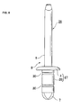
- FIG 8 shows the blind rivet 26 in the fourth embodiment of the present invention.
- two circumferential grooves 30 are formed on the outer periphery of the sleeves 29 on the rivet body 27 at different positions axially.
- one circumferential groove can be formed or many more circumferential grooves can be formed. Because the rest of the configuration is the same as the blind rivet 1 shown in FIG 1 through FIG 4 , further explanation is omitted.
- the two circumferential grooves 30 shown in the figure are added to the expanded and deformed portion 14 in FIG 21 to form one more expanded and deformed portion in the portion of the sleeve 29 between the two circumferential grooves.
- the second expanded and deformed portion between the two circumferential grooves is added to the first expanded and deformed portion at the tip (bottom end) of the sleeve 29 in the axial direction for more reliable fastening.
- Two expanded and deformed portions can be added to the sleeve even when one circumferential groove is used.
Landscapes
- Engineering & Computer Science (AREA)
- General Engineering & Computer Science (AREA)
- Mechanical Engineering (AREA)
- Insertion Pins And Rivets (AREA)
- Connection Of Plates (AREA)
Abstract
Description
- The present invention relates to a blind rivet and, more specifically, to a blind rivet able to keep the broken mandrel portion attached to the rivet from dropping off the rivet body after fastening.
- A blind rivet comprises a rivet body consisting of a hollow sleeve and a hollow flange formed at one end of the sleeve with a larger diameter than the sleeve, and a mandrel consisting of a shaft portion extending from the flange through the rivet body and a head integrally connected to the shaft portion with a diameter greater than the inner diameter of the sleeve arranged adjacent to the sleeve end on the side opposite that of the flange. During the blind rivet fastening operation, the shaft portion of the mandrel extending from the rivet body is inserted and held in the nose of the fastening tool. The rivet body with the mandrel passing though is inserted with the mandrel head in front into the attachment hole of the attached component aligned with the attachment hole of the attached member. When the mandrel head is sticking out of the rear surface of the attached member and the flange on the rivet body has come into contact with the attached component, the mandrel shaft extending from the flange on the attached component side is forcibly drawn out by the operation of the fastening tool until it breaks off. The forcible drawing of the mandrel shaft causes the mandrel head to pull the sleeve portion on the rear surface of the attached member towards the flange side. A portion of the sleeve (for example, the portion at the end near the mandrel head) expands outward radially and is deformed. The attached member and the attached component are interposed between the flange and the expanded and deformed portion of the sleeve, and the attached member and the attached component are fastened by the blind rivet. This fastening operation joins the attached component to the attached member.
- Because the mandrel shaft portion of the broken mandrel held by the fastening tool is accommodated in the fastening tool in order to expand and deform the sleeve, this portion can be discarded from the fastening tool at a location away from the attached member at the end of the fastening operation. However, the broken shaft portion of the mandrel remains with the head on the rivet body connected to the attached member. Because the mandrel portion is not connected to the rivet body, gravity often causes it to drop off the rivet body. The mandrel shaft portion attached to the dropped off mandrel loses motion on the rear surface of the attached member, making noise and sometimes damaging the rear surface of the attached member. Therefore, the mandrel portion attached to the broken off rivet should be kept from dropping off the rivet body.
- In the blind rivet described in
JP 6-147208 A US 2,756,624 A , the broken off mandrel portion attached to the head has a head with a shape that keeps it from dropping off the rivet body. In the blind rivet ofJP 6-147208 A US 2,756,624 A , the mandrel head has a shape with a nearly round horizontal cross-section in the root portion adjacent to the mandrel shaft and an oval-shaped horizontal cross-section in the tip portion. The end of the sleeve on the rivet body expanded and deformed by the mandrel head is first expanded and deformed into a round shape by the head portion which has a round horizontal cross-section. However, it is then deformed into an oval shape from the round shape by the expanded and deformed end of the sleeve, and finally into a shape in which the pair of long sides on the oval move closer to each other to cover the end surface of the rivet. The deformation causes the end surface of the broken mandrel head to be covered by the deformed portion of the end surface of the sleeve, and the mandrel portion attached to the broken rivet is kept from dropping off the rivet body. - The blind rivet in
JP 6-147208 A US 2,756,624 A can keep the broken mandrel portion attached to the rivet from dropping off the rivet body. However, when the head portion with a round horizontal cross-section in the blind rivet ofJP 6-147208 A US 2,756,624 A is deformed from a round horizontal cross-section to an oval-shaped horizontal cross-section by the sleeve which is expanded and deformed into a round shape by the head portion with a nearly round horizontal cross-section, the sleeve end of the rivet body is expanded and deformed again which weakens the strength of the expanded and deformed sleeve portion. As mentioned earlier, the attached member and the attached component are interposed between the flange and the expanded and deformed portion of the sleeve, and the attached member and the attached component are fastened by the blind rivet. This fastening operation joins the attached component to the attached member. When the strength of the expanded and deformed portion of the sleeve is weakened, the fastening strength of the blind rivet is reduced. As a result, the joining strength of the attached member and the attached component is also reduced. - The object of the present invention is to provide a blind rivet that can keep the broken mandrel portion from dropping off the rivet body and that can maintain high fastening strength for the blind rivet.
- In order to achieve this object, the present invention is a blind rivet comprising a rivet body consisting of a hollow sleeve and a hollow flange formed at one end of the sleeve with a larger diameter than the sleeve, and a mandrel consisting of a shaft portion extending from the flange through the rivet body and a head integrally connected to the shaft portion with a diameter greater than the inner diameter of the sleeve arranged adjacent to the sleeve end on the side opposite that of the flange, an attached member and an attached component being fastened and joined together by expanding a portion of the sleeve on the rivet body passed through attachment holes in the attached member and the attached component, and interposing the attached member and the attached component between the expanded portion and the flange. The blind rivet of the present invention is characterized in that the head has a maximum diameter portion as viewed from the front formed in the root portion adjacent to the shaft portion, a maximum diameter portion as viewed from the side in a direction perpendicular to the view from the front formed on the side of the tip of the rivet, the maximum diameter portion as viewed from the front being formed in a different location axially than the maximum diameter portion as viewed from the side with the axis of the rivet being arranged vertically and the tip of the rivet facing downward, and in that the horizontal cross-section of the head has a first ellipse formed in the maximum diameter portion as viewed from the front, and a second ellipse formed in the maximum diameter portion as viewed from the side with the long axis thereof perpendicular to the long axis of the first ellipse, the horizontal cross-sectional shape of the head gradually changing in the axial direction so as to continue from the first ellipse to the second ellipse, each one of the horizontal cross-sections having the same circumferential length at different axial positions on the head.
- As mentioned above, the head has a maximum diameter portion as viewed from the front formed in the root portion adjacent to the shaft portion, and a maximum diameter portion as viewed from the side in a direction perpendicular to the view from the front formed on the side of the tip of the rivet. Also, the horizontal cross-section of the head has a first ellipse formed in the maximum diameter portion as viewed from the front, and a second ellipse formed in the maximum diameter portion viewed from the side with the long axis thereof perpendicular to the long axis of the first ellipse, the horizontal cross-sectional shape of the head gradually changing in the axial direction so as to continue from the first ellipse to the second ellipse, each one of the horizontal cross-sections having the same circumferential length at different axial positions on the head. As a result, the end of the sleeve expanded and deformed by the rivet covers a portion of the surface at the tip of the rivet, keeping the broken mandrel portion attached to the rivet from dropping off the rivet body. Because the circumferential length of the rivet is set to keep the sleeve at a constant thickness while the sleeve is expanded and deformed, the fastening strength of the blind rivet can be maintained at a high level.
- In another embodiment of the blind rivet, the head is formed in a semicircular shape as viewed from the front, the diameter becoming smaller from the root portion towards the tip, and the head is formed in a trapezoidal shape as viewed from the side, the short side being in the root portion and the long side being at the tip. This rivet has a pair of shoulders coming into contact with the sleeve end in the root portion as viewed from the front, and the rivet has a pair of inclined surfaces expanding outward radially from the root portion in the direction of the tip as viewed from the side. A triangular cut can be formed at the tip of the rivet in the portion forming a trapezoidal shape as viewed from the side. This saves on material costs and reduces the overall weight. In another embodiment of the blind rivet, the head is formed in a triangular shape as viewed from the front, the diameter becoming smaller from the root portion towards the tip, and the head is formed in a semicircular shape as viewed from the side, the diameter becoming larger from the root portion towards the tip. This rivet has a pair of curved shoulders coming into contact with the sleeve end in the root portion as viewed from the front, and the rivet has a pair of inclined surfaces expanding outward radially from the root portion in the direction of the tip as viewed from the side.
- In still another embodiment of the blind rivet, the head is formed in a circular shape as viewed from the tip of the rivet on the bottom. Here, a mandrel consisting of a head and shaft can be fashioned from a round rod. In other words, the mandrel can be formed as simply as the prior art and any additional steps can be eliminated. In yet another embodiment of a blind rivet, two circumferential grooves are formed in the outer peripheral surface of the sleeve in different positions axially. This creates a second expanded and deformed portion between the two circumferential grooves in addition to the first expanded and deformed portion at the tip (bottom end) of the sleeve for more secure fastening. A single circumferential groove can also be formed.
- Brief Explanation of the Figures
- FIG 1
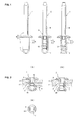
- shows the blind rivet in the first embodiment of the present invention. FIG 1 (A) is a front view of the blind rivet in the first embodiment, FIG 1 (B) is a partial horizontal cross-sectional front view of the blind rivet showing a vertical cross-sectional front view of the body of the blind rivet in FIG 1 (A), and FIG 1 (C) is a partial horizontal cross-sectional side view of the blind rivet showing a vertical cross-sectional view of the body of the blind rivet in FIG 1 (A).
- FIG 2
- shows an attached member and an attached component fastened together with the blind rivet in
FIG 1. FIG 2 (A) is a partial horizontal cross-sectional front view of the blind rivet in FIG 1 (B) after fastening,FIG 2 (B) is a partial horizontal cross-sectional side view of the blind rivet in FIG 1 (C) after fastening, andFIG 2 (C) is a bottom view of the blind rivet inFIG 2 (A) . - FIG 3
- shows the portion of the blind rivet in
FIG 1 with the head of the mandrel and the adjacent shaft portion.FIG 3 (A) is a front view of the head and shaft portion,FIG 3 (B) is a side view of the head and shaft portion inFIG 3 (A), FIG 3 (C) is a bottom view of the head inFIG 3 (A), and FIG 3 (D) is a perspective view of the head and shaft portion ofFIG 3 (A) . - FIG 4
- is a graph showing the horizontal cross-sectional shapes and the circumferential lengths of the mandrel head in the blind rivet of
FIG 1 along the axial length of the head.FIG 4 continues from graph (A) to graph (B). In the graph, the horizontal axis indicates the axial length of the head in mm units from the starting point at the boundary with the shaft towards the tip (the bottom end inFIG 1 ), and the vertical axis indicates the circumferential length of the horizontal cross-section of the head in mm units. The various figures arranged horizontally at the top of graph (B) indicate the horizontal cross- sectional shape of the head at the position corresponding to the axial length of the head. - FIG 5
- shows the portion of the blind rivet in the second embodiment of the present invention containing the head of the mandrel and the adjacent shaft portion.
FIG 5 (A) is a front view of the head and shaft portion,FIG 5 (B) is a side view of the head and shaft portion inFIG 5 (A), FIG 5 (C) is a bottom view of the head inFIG 5 (A), and FIG 5 (D) is a perspective view of the head and shaft portion inFIG 5 (A) . - FIG 6
- is a graph showing the horizontal cross-sectional shapes and the circumferential lengths of the mandrel head in the blind rivet of
FIG 5 along the axial length of the head. In the graph, the horizontal axis indicates the axial length of the head in mm units from the starting point at the boundary with the shaft towards the tip, and the vertical axis indicates the circumferential length of the horizontal cross-section of the head in mm units. The various figures arranged horizontally at the top of graph indicate the horizontal cross-sectional shape of the head at the position corresponding to the axial length of the head. - FIG 7
- shows the portion of the blind rivet in the second embodiment of the present invention containing the head of the mandrel and the adjacent shaft portion.
FIG 7 (A) is a front view of the head and shaft portion,FIG 7 (B) is a side view of the head and shaft portion inFIG 7 (A), FIG 7 (C) is a bottom view of the head inFIG 7 (A), and FIG 7 (D) is a perspective view of the head and shaft portion inFIG 7 (A) . - FIG 8
- is a front view of the blind rivet in the fourth embodiment of the present invention.
- The following is an explanation of the blind rivets in embodiments of the present invention with reference to the figures.
FIG 1 through FIG 4 show theblind rivet 1 in the first embodiment, theblind rivet 1 after being fastened, the head of the mandrel and the shaft portion of the mandrel adjacent to the head in theblind rivet 1 of the first embodiment, and how the horizontal cross-sectional shapes and the circumferential lengths change along the axial length of the mandrel head.FIG 5 andFIG 6 show the head of the mandrel and the shaft portion of the mandrel adjacent to the head in the blind rivet of the second embodiment, and how the horizontal cross-sectional shapes and the circumferential lengths change along the axial length of the mandrel head.FIG 7 shows the head of the mandrel and the shaft portion of the mandrel adjacent to the head in the blind rivet of the third embodiment.FIG 8 shows the blind rivet in the fourth embodiment. - The following is an explanation of the blind rivet in the first embodiment with reference to
FIG 1 through FIG 4 . FIGS 1 (A) through (C) show the overall shape of theblind rivet 1. Theblind rivet 1 comprises arivet body 5 consisting of ahollow sleeve 2 and ahollow flange 3 formed at one end of thesleeve 2 with a larger diameter than thesleeve 2, and amandrel 9 consisting of ashaft portion 6 extending from theflange 3 through therivet body 5 and ahead 7 integrally connected to theshaft portion 6 with a diameter greater than the inner diameter of thesleeve 2 arranged adjacent to thesleeve 2 end on the side opposite that of theflange 3. Therivet body 5 and themandrel 9 are integrally formed of a metal material that is the same as that of conventional blind rivets. The two components, therivet body 5 and themandrel 9, as shown in FIGS 1 (A) through (C), form a single component, ablind rivet 1, when themandrel 9 is passed through therivet body 5 in the assembly process. Examples of metal materials that can be used to form themandrel 9 and therivet body 5 include iron, stainless steel and aluminum. - As shown in FIGS 1 (B) and (C), a
breakable portion 10 with a diameter smaller than the rest of the shaft portion is formed in theshaft portion 5 of themandrel 9 near thehead 7. Thebreakable portion 10 is surrounded by thesleeve 2 of therivet body 5 before being fastened, and is formed between theflange 3 and thehead 7. The breaking strength of thebreakable portion 10 is determined by the combination of the drawing force of themandrel 9 and the expansion and deformation force of thesleeve 2 when thesleeve 2 is expanded and deformed by thehead 7. The drawing force of the mandrel should not cause breakage until the attached member and the attached component are securely interposed between theflange 3 and the expanded and deformed portion of thesleeve 2. It should also not be excessive before the attached member and the attached component have been interposed. -
FIG 2 shows the attachedcomponent 13 joined with the attachedmember 11 by the fastening of theblind rivet 1. During theblind rivet 1 fastening operation, theshaft portion 6 of themandrel 9 extending from theflange 3 of therivet body 5 is inserted by the operator and held in the nose of the fastening tool (not shown). Next, therivet body 5 with themandrel 9 passing though is inserted with themandrel head 7 in front into the attachment hole of the attachedcomponent 13 aligned with the attachment hole of the attachedmember 11. Thehead 7 of themandrel 9 sticks out of the rear surface of the attachedmember 11 and theflange 3 on therivet body 5 comes into contact with the attachedcomponent 13. In this state, the operator operates the fastening tool and theshaft portion 6 of themandrel 9 extending from theflange 3 on the side with the attachedcomponent 13 is drawn against theflange 3 until it breaks in thebreakable portion 10. By forcibly drawing theshaft portion 6, thehead 7 of themandrel 9 is pressed strongly against the end of thesleeve 2, thehead 7 is pulled into the portion of thesleeve 2 on the rear surface side of the attachedcomponent 11, and a portion of the sleeve 2 (i.e., the portion at the end of thesleeve 2 adjacent to the mandrel head 7) is deformed so as to expand radially, forming the expanded anddeformed portion 14 shown inFIG 2 . Because the expanded anddeformed portion 14 of thesleeve 2 is strongly pulled by themandrel head 7 in the axial direction towards the flange 2 [sic], the attachedmember 11 making contact with the expanded anddeformed portion 14 and the attachedcomponent 13 making contact with theflange 3 are firmly interposed working with theflange 3. Thus, theblind rivet 1, as shown inFIG 2 , interposes the attachedmember 11 and the attachedcomponent 13 between the expanded anddeformed portion 14 of thesleeve 2 and theflange 3, the attachedmember 11 and the attachedcomponent 13 are fastened, and the attachedmember 11 and the attachedcomponent 13 are joined by the fastening operation. - The
blind rivet 1 has ahead 7 with a shape that keeps the broken mandrel portion with the head attached from dropping off therivet body 5. SeeFIG 3 . InFIGS 3 (A) and (B) , thehead 7 is aligned in the axial direction (vertically in the figure) with the root portion, or theboundary portion 22 with theshaft portion 6. - As shown in the front view in
FIG 3 (A) , a pair ofshoulders 17 is formed in thehead 7 at theboundary portion 22 with the shaft portion 6 (i.e., in the root portion) diametrically facing the plane perpendicular to theaxis 15 of thehead 7 extending upward (i.e., themandrel 9 including the shaft portion 6). Because thehead 7 is aligned in the axial direction (vertically in the figure) with respect to theboundary portion 22 with theshaft portion 6 inFIGS 3 (A) and (B) , theshoulders 17 inFIGS 3 (A) and (B) are shown at the same axial height. For example, thehead 7 can be obtained by machining a round rod with a diameter corresponding to the diameter of theshoulders 17 into the predetermined shape [seeFIG 3 (D) ]. - In the front view [
FIG 3 (A) ], the diameter of thehead 7 is reduced (constricted) from theshoulders 17 towards the bottom end (i.e., the tip) with the tip of thehead 7 extending vertically along theaxis 15 of thehead 7 facing downward. In the side view [FIG 3 (B) ], the head has a trapezoidal shape with a diameter shorter at the upper end (which substantially the same as the shaft portion 6) and a diameter longer at the tip or lower end (which is substantially the same as the portion with the shoulders 17). In the bottom view inFIG 3 (C) , the shape as viewed from the bottom end (tip) is nearly as round as a round rod. In thehead 7, themaximum diameter portion 19 in the side view [FIG 3 (B) ] has substantially the same diameter as themaximum diameter portion 18 in the front view [FIG 3 (A) ]. In the figures, themaximum diameter portion 18 as viewed from the front and themaximum diameter portion 19 as viewed from the side are staggered positionally along theaxis 15. A pair ofinclined surfaces 21 is formed in which the radius increases outward radially from theboundary portion 22 towards the bottom end (top) in the diametrical direction as viewed from the side and perpendicular to the pair ofshoulders 17 facing them in the perpendicular direction. The length of the maximum diameter portion 18 (and maximum diameter portion 19) is selected to firmly interpose the attached component and the attached member between theflange 3 and the portion of thesleeve 2 expanded and deformed by the maximum diameter portion 18 (and maximum diameter portion 19) and to expand and deform thesleeve 2 enough to maintain the strength of thesleeve 2. In the other embodiments, it is selected in the same manner. - As mentioned above, the
maximum diameter portion 18 as viewed from the front [FIG 3 (A) ] and themaximum diameter portion 19 as viewed from the side [FIGS 3 (B) ] are staggered along theaxis 15 with themaximum diameter portion 18 along the upper portion of theaxis 15 and themaximum diameter portion 19 along the lower portion of theaxis 15. The horizontal cross-sectional shape of thehead 7 changes along the axis of thehead 7 from a first ellipse formed in the portion with themaximum diameter portion 18 as viewed from the front [FIG 3 (A) ] to a second ellipse with the long axis perpendicular to the long axis of the first ellipse formed in the portion with themaximum diameter portion 19 as viewed from the side [FIG 3 (B) ]. The horizontal cross-sectional shape of thehead 7 is shown inFIG 4 (B) . The horizontal cross-section of thehead 7 is formed so that the circumferential length is the same at different positions along the axis. - In the fastening operation of the
blind rivet 1, first, the end of thesleeve 2 of therivet body 5 expanded and deformed by thehead 7 of themandrel 9 is drawn through theshaft portion 6 of the mandrel from the fastening tool, and is subjected to strong axial deformation force from the pair ofshoulders 17 on thehead 7. The pair ofinclined surfaces 21 facing the pair ofshoulders 17 in the perpendicular direction are embedded inside thesleeve 2. The pair ofinclined surfaces 21 embedded inside thesleeve 2 deforms the end of thesleeve 2 in the portion with theinclined surfaces 21 so as to make it smaller radially. The strong axial deformation force sustained from the pair ofshoulders 17 expands and deforms the end of thesleeve 2 outward radially as the radius grows to accept theshoulders 17. This expansion and deformation pushes thehead 7 inside from the end of thesleeve 2 and moves axially. The inside of thesleeve 2 is deformed outward radially in accordance with the horizontal cross-sectional shape of thehead 7. For this deformation, see also the horizontal cross-sectional shape of thehead 7 inFIG 4 . - The horizontal cross-sections of the
rivet 7 producing this deformation are rendered at the top of the graph inFIG 4 (B) at the various locations corresponding to the moving length of therivet 7 along the horizontal axis of the graph. As shown inFIG 4 (B) , in the horizontal cross-sectional shape (a) corresponding to the first ellipse in thehead 7, the expansion and deformation from the pair ofshoulders 17 are parallel. As thehead 7 moves upward inFIG 1 , the horizontal cross-sectional shape of thehead 7 positioned at the end of thesleeve 2 changes to shapes (b), (c) and (d). As the shape changes, the end of thesleeve 2 also changes to shapes (b), (c) and (d). Because at horizontal cross-sectional shape (e) of thehead 7, the diameter of the portion at theinclined surfaces 21 formed in the trapezoidal shape as viewed from the side [FIG 3 (B) ] is substantially the same as the diameter of the portion formed in a round shape as viewed from the front [FIG 3 (A) ], the deformed portion of thesleeve 2 is somewhat square and round. When this position is passed, the horizontal cross-sectional shape of thehead 7 changes to shapes (f), (g) and (h) as it approaches the second ellipse (i). As a result, the long sides formed by the trapezoid shape as viewed from the side [FIG 3 (B) ] act to deform it into an elliptical shape that is long in the perpendicular direction. When the horizontal cross-sectional shape (k) [sic] of thehead 7 reaches its final horizontal cross-sectional shape (i) corresponding to the second ellipse, the end portion of thesleeve 2 has been expanded and deformed into an elliptical shape that is long in the perpendicular direction and short in the horizontal direction. The pair of long side portions facing in the horizontal direction ride over the tip or bottom end of the head portion formed into a semi-circular shape as viewed from the front [FIG 3 (A) ] and cause deformation inside as shown by expanded anddeformed portion 14 inFIG 2 (A) . In other words, the pair of long side portions of the ellipse in the deformed portion of thedeformed sleeve 2 are deformed into a shape in which they nearly come into contact with each other and cover the end surface of thehead 7. This keeps thebroken mandrel shaft 6 with the attachedhead 7 from dropping off therivet body 5. - The
head 7 has a semicircular shape in which the diameter becomes reduced (constricted) from theshoulders 17 to the tip (lower end) as viewed from the front [FIG 3 (A) ], and has a trapezoid shape in which the diameter is about the same as theshaft portion 6 at the top end and in which the diameter is larger at the lower end or tip (about the same diameter as the shoulder portions 17) as viewed from the side [FIGS 3 (B) ]. As shown in the bottom view inFIG 3 (C) , the shape viewed from the tip (lower end) is nearly round, and the diameter of thelarge diameter portion 18 as viewed from the front [FIG 3 (A) ] is nearly the same as the diameter of thelarger diameter portion 19 as viewed from the side [FIG 3 (B) ]. As mentioned earlier, themandrel 9 can be formed from a round rod. This is machined so that the portion of thehead 7 has a diameter that is larger than theshaft portion 6 so as to form theshoulder portions 17, abreakable portion 10 is formed in a part of theshaft portion 6, and thehead 7 is given a semicircular shape and trapezoidal shape. In this way, a mandrel with ahead 7 can be manufactured in a single step, and the number of steps needed to form the head is the same as a mandrel of the prior art. This means costs are not increased. - In the
head 7, the circumferential length of the horizontal cross-section of thehead 7 is nearly the same at each position along the axial direction of thehead 7. In the head of the mandrel for the blind rivet of the first embodiment shown inFIG 4 (A) and (B) , the axial length of the head is 2 mm. The circumferential lengths of the horizontal cross-sections along the axis between 0.1 mm and 1.5 mm are in the 9.00 mm to 11.00 mm range or approximately 11.00 mm. More specifically, the circumferential lengths of the horizontal cross-sections of thehead 7 along the axis between 0.0 mm and 0.2 mm are between 9.00 mm and 10.00 mm, and the circumferential length of the horizontal cross-sections of the head along the axis between 0.5 mm and 1.4 mm is approximately 11.00 mm. Because the inner circumferential length of the expanded and deformed portion at the end of thesleeve 2 is fixed, deterioration in the strength of the sleeve in the expanded and deformed portion can be prevented, the strength of the expanded and deformed portion can be maintained, and the fastening strength of the blind rivet can be kept constant. As a result, the strength joining the attachedcomponent 13 to the attachedmember 11 can be kept constant and high fastening strength can be maintained. Also, the circumferential lengths in the head 7 a short distance axially from theboundary portion 22 with theshaft portion 6 is shorter than the circumferential lengths at a greater distance. As a result, thehead 7 is easily inserted into thesleeve 2 at the beginning of the expansion and deformation at the end of thesleeve 2, and the expanding and deforming is easier to achieve. -
FIG 5 andFIG 6 show thehead 7A of the mandrel in the blind rivet of the second embodiment. InFIGS 5 (A) and (B) , theboundary portion 22 with theshaft portion 6 is aligned with thehead 7A in the axial position (vertically in the figure). As shown in the front view ofFIG 5 (A) , a pair ofshoulders 17A is formed in thehead 7A at theboundary portion 22 with theshaft portion 6 diametrically with respect to the horizontal plane which is perpendicular to thevertical axis 15. As in the case ofhead 7,head 7A is obtained by machining a round rod to a predetermined shape. Inhead 7A, the shoulders have a somewhat different shape than theshoulders 17 inhead 7. The outermost peripheral portion is formed intocurved shoulders 17A with fillets (roundness) 23. This makes it easier to insert thehead 7A into thesleeve 2 at the beginning the expanding and deforming at the end of thesleeve 2 and the expanding and deforming of thesleeve 2 can begin more easily. Thehead 7A is formed so that the triangle-shaped diameter is reduced (constricted) from thecurved shoulders 17A and thefillets 23 towards the bottom end (tip) as viewed from the front [FIG 5 (A) ], and so that the upper end has a semicircular shape that is reduced or constricted as viewed from the side [FIG 5 (B) ]. As shown in the bottom view inFIG 5 (C) , the shape of thehead 7A when viewed from the bottom end (i.e., from the tip) is nearly as round as a round rod, and the diameter of themaximum diameter portion 18A as viewed from the front [FIG 5 (A) ] is nearly the same as the diameter of themaximum diameter portion 19A as viewed from the side [FIG 5 (B) ].Maximum diameter portion 18A andmaximum diameter portion 19A are staggered positionally along theaxis 15. Also, a pair ofinclined surfaces 21A are formed in the diametrical direction perpendicular to the pair ofshoulders 17A opposing them in the diametrical direction. The diameter of these surfaces increases radially from the boundary portion towards the bottom end (tip). - In the case of
head 7A, as in the case ofhead 7, the shape of the horizontal cross-section of thehead 7A changes continually along the axis of thehead 7A from a first ellipse formed in the portion with themaximum diameter portion 18A as viewed from the front [FIG 5 (A) ] to a second ellipse with a long axis perpendicular to the long axis of the first ellipse formed in the portion with themaximum diameter portion 19A as viewed from the side [FIG 5 (B) ]. The shapes of the horizontal cross-sections of thehead 7A are shown inFIG 6 . The horizontal cross-sections of thehead 7A are formed with the same circumferential length at the different positions in the axial direction. - During the fastening operation, the end of the
sleeve 2 to be expanded and deformed by thehead 7A of themandrel 9 is subjected to strong axial deforming force from the pair ofshoulders 17A on thehead 7A as theshaft portion 6 is drawn from the fastening tool, and the pair ofinclined surfaces 21A opposing the pair ofshoulders 17A orthogonally are submerged inside thesleeve 2. The portion with the pair ofinclined surfaces 21A can be deformed so that the radius at the end of thesleeve 2 becomes smaller, and the portion with the pair ofshoulders 17A is expanded and deformed radially outward so that the radius at the end of thesleeve 2 can receive theshoulders 17A. Thehead 7A moves upward radially inside thesleeve 2, and the inside of thesleeve 2 is deformed outward radially by the cross-sectional shape of thehead 7A. - The horizontal cross-sections of the
rivet 7A producing this deformation are rendered at the top of the graph inFIG 6 at the various locations corresponding to the moving length of therivet 7A along the horizontal axis of the graph. As shown inFIG 6 , in the horizontal cross-sectional shape (a) corresponding to the first ellipse in thehead 7A, the expansion and deformation of the end of thesleeve 2 by the pair ofshoulders 17A is in the horizontal direction. As thehead 7A moves above the shaft portion 15 (upward inFIG 1 ), the end of thesleeve 2 is deformed by the horizontal cross-sectional shape of thehead 7A changing to shapes (b), (c) and (d). At the horizontal cross-sectional shape (e) ofhead 7A, the diameter of the portion with theinclined surface 21A as viewed from the side [FIG 5 (B) ] is nearly the same as the diameter as viewed from the front [FIG 6 (A) ]. In other words, the deformed portion of thesleeve 2 is somewhat square and round. When thehead 7A passes this position, the horizontal cross-sectional shape of thehead 7A changes to shapes (f), (g) and (h). The portion with the semi-circular shape as viewed from the side [FIG 6 (B) ] acts to deform thesleeve 2 into an elliptical shape that is long in the perpendicular direction. The expansion and deformation of thesleeve 2 moves through the shape of horizontal cross-section (h) of thehead 7A to the final shape of horizontal cross-section (i). When the end of thesleeve 2 is deformed to the shape corresponding to cross-sectional shape (i) with the second ellipse inhead 7A, it has been expanded and deformed into an elliptical shape that is long in the perpendicular direction and short in the horizontal direction. As indicated by the expanded anddeformed portion 14 inFIG 2 (A) , the bottom end or tip of thehead 7A rides over and deforms the sleeve from the inside. The pair of long sided portions of the ellipse in the deformed sleeve portion are deformed so as to come closer to each other and cover the end surface of the head 7 [sic]. The end surface of thehead 7A is covered by the deformed portion at the end surface of thesleeve 2, and thebroken mandrel shaft 6 with the attached head 7 [sic] is kept from falling off therivet body 5. - In the second embodiment, the
head 7A has a nearly round shape as viewed from the tip (end) in the bottom view ofFIG 5 (C) . In other words, the diameter of themaximum diameter portion 18A as viewed from the front [FIG 5 (A) ] is nearly the same as the diameter of themaximum diameter portion 19A as viewed from the side [FIG 5 (B) ]. Therefore, the mandrel can be formed out of a round rod. This is machined so that theshaft portion 6 has a small diameter, the portion with thehead 7A has a larger diameter than theshaft portion 6 so as to formshoulders 17A, a breakable portion is formed in a section of theshaft portion 6, and thehead 7A has a triangular shape as viewed from the front and a semi-circular shape as viewed from the side. As a result, the number of steps needed to form thehead 7A is the same as a conventional mandrel, and there is no increase in cost. - In the
head 7A, the circumferential length of the horizontal cross-section of thehead 7A is nearly the same at each position along the axial direction of thehead 7A. In the head of the mandrel for the blind rivet of this embodiment shown inFIG 6 , the axial length of the head is 2.3 mm. The circumferential lengths of the horizontal cross-sections along the axis between 0.1 mm and 1.5 mm are in the 9.00 mm to 11.00 mm range or approximately 11.00 mm. More specifically, the circumferential lengths of the horizontal cross-sections of thehead 7A along the axis between 0.0 mm and 0.2 mm are between 9.00 mm and 11.00 mm, and the circumferential length of the horizontal cross-sections of the head along the axis between 0.3 mm and 1.1 mm is approximately 11.00 mm. Because the inner circumferential length of the expanded and deformed portion at the end of thesleeve 2 is fixed, deterioration in the strength of the sleeve in the expanded and deformed portion can be prevented, the strength of the expanded and deformed portion can be maintained, and the fastening strength of the blind rivet can be kept constant. As a result, the strength joining the attachedcomponent 13 to the attachedmember 11 can be kept constant and high fastening strength can be maintained. Thehead 7A hasfillets 23 and the circumferential lengths a short distance axially from theboundary portion 22 with theshaft portion 6 is shorter than the circumferential lengths at a greater distance. As a result, thehead 7A is easily inserted into thesleeve 2 at the beginning of the expansion and deformation at the end of thesleeve 2, and the expanding and deforming is easier to achieve. -
FIG 7 shows thehead 7B of the mandrel in the blind rivet of the third embodiment. InFIGS 7 (A) and (B) , thehead 7B is described as being aligned axially (along the axis 15) with theboundary portion 22 with theshaft portion 6.Head 7B nearly has the same shape as thehead 7 in the first embodiment. However, the shape as viewed from the side [FIG 7 (B) ] is not trapezoidal like thehead 7. Instead, a triangle-shaped lightening cut 25 is formed in the lower portion (tip). In order to maintain the strength on the lower end (tip) of thehead 7B, thecut 25 does not have to be triangular. Even a round lightening cut can be made in the lower end (tip) of thehead 7B. As shown in the front view ofFIG 7 (A) , a pair of shoulders is formed. As shown in the front view ofFIG 7 (A) , a pair ofshoulders 17B is formed in thehead 7B at theboundary portion 22 with theshaft portion 6 facing a plane diametrically which is orthogonal horizontally to thevertical axis 15. Thehead 7B is obtained by machining a round rod to a predetermined shape. Thehead 7B is formed so that the semi-circular diameter is constricted from theshoulders 17B towards the bottom end (tip) as viewed from the front [FIG 7 (A) ], and so that the bottom end of a trapezoidal shape that is short on the top end and long on the bottom end includes a cut 25 [FIG 5 (B) ] [sic]. As shown in the bottom view inFIG 7 (C) , the shape of thehead 7B when viewed from the bottom end (i.e., from the tip) is nearly as round as a round rod, and the diameter of themaximum diameter portion 18B as viewed from the front [FIG 7 (A) ] is nearly the same as the diameter of themaximum diameter portion 19B as viewed from the side [FIG 5 (B) ] [sic].Maximum diameter portion 18B andmaximum diameter portion 19B are staggered positionally along theaxis 15. The shape of the head changes from a first ellipse formed in the portion with themaximum diameter portion 18B to a second ellipse with the long axis perpendicular to the long axis of the first ellipse formed in the portion with themaximum diameter portion 19B as viewed from the side. Also, a pair ofinclined surfaces 21 B with a radius that increases from theboundary portion 22 towards the bottom end (tip). In the case ofhead 7B, as in the case ofhead 7, the circumferential lengths of the horizontal cross-sections of thehead 7B are nearly the same at the various positions along the axis of thehead 7B. Therefore, in thehead 7B after the fastening operation, the end surface of thehead 7B is covered by the deformed portion at the end surface of thesleeve 2, and thebroken head 7B andshaft portion 6 are kept from dropping off therivet body 5. - Also, the inner circumferential length of the expanded and deformed portion at the end of the
sleeve 2 is fixed, the strength from the expansion and deformation of the sleeve is fixed, deterioration in the strength of the sleeve from the increased expansion and deformation is prevented, the strength of the expanded and deformed portion is fixed, and the fastening strength of the blind rivet is fixed. As a result, the strength joining the attachedcomponent 13 to the attachedmember 11 is fixed, and high fastening strength can be maintained. By forming acut 25, the amount of material in the rivet portion and the weight of the rivet portion can be reduced. -
FIG 8 shows theblind rivet 26 in the fourth embodiment of the present invention. Here, twocircumferential grooves 30 are formed on the outer periphery of thesleeves 29 on therivet body 27 at different positions axially. There are twocircumferential grooves 30 in the example shown in the figure. However, one circumferential groove can be formed or many more circumferential grooves can be formed. Because the rest of the configuration is the same as theblind rivet 1 shown inFIG 1 through FIG 4 , further explanation is omitted. In the fastening operation, the twocircumferential grooves 30 shown in the figure are added to the expanded anddeformed portion 14 in FIG 21 to form one more expanded and deformed portion in the portion of thesleeve 29 between the two circumferential grooves. As a result, the second expanded and deformed portion between the two circumferential grooves is added to the first expanded and deformed portion at the tip (bottom end) of thesleeve 29 in the axial direction for more reliable fastening. Two expanded and deformed portions can be added to the sleeve even when one circumferential groove is used.
Claims (9)
- A blind rivet (1) comprising a rivet body (5) consisting of a hollow sleeve (2) and a hollow flange (3) formed at one end of the sleeve (2) with a larger diameter than the sleeve (2), and a mandrel (9) consisting of a shaft portion (6) extending from the flange (3) through the rivet body (5) and a head (7) integrally connected to the shaft portion (6) with a diameter greater than the inner diameter of the sleeve (2) arranged adjacent to the sleeve end on the side opposite that of the flange (3), characterized in thatthe head (7) has a maximum diameter portion (18) as viewed from the front formed in the root portion adjacent to the shaft portion (6), a maximum diameter portion (19) as viewed from the side in a direction perpendicular to the view from the front formed on the side of the tip of the rivet, the maximum diameter portion (18) as viewed from the front being formed in a different location axially than the maximum diameter portion (19) as viewed from the side with the axis of the rivet being arranged vertically and the tip of the rivet facing downward, and in thatthe horizontal cross-section of the head (7) has a first ellipse formed in the maximum diameter portion (18) as viewed from the front, and a second ellipse formed in the maximum diameter portion (19) as viewed from the side with the long axis thereof perpendicular to the long axis of the first ellipse, the horizontal cross-sectional shape of the head (7) gradually changing in the axial direction so as to continue from the first ellipse to the second ellipse, each one of the horizontal cross-sections having the same circumferential length at different axial positions on the head (7).
- The blind rivet of claim 1, wherein the head (7) is formed in a semicircular shape as viewed from the front, the diameter becoming smaller from the root portion towards the tip, and wherein the head (7) is formed in a trapezoidal shape as viewed from the side, the short side being in the root portion and the long side being at the tip.
- The blind rivet of claim 2, wherein the rivet has a pair of shoulders (17) coming into contact with the sleeve end in the root portion as viewed from the front, and the rivet has a pair of inclined surfaces (21) expanding outward radially from the root portion in the direction of the tip as viewed from the side.
- The blind rivet of claim 1, wherein the head (7A) is formed in a triangular shape as viewed from the front, the diameter becoming smaller from the root portion towards the tip, and wherein the head (7A) is formed in a semicircular shape as viewed from the side, the diameter becoming larger from the root portion towards the tip.
- The blind rivet of claim 4, wherein the rivet has a pair of curved shoulders (17A) coming into contact with the sleeve end in the root portion as viewed from the front, and the rivet has a pair of inclined surfaces (21A) expanding outward radially from the root portion in the direction of the tip as viewed from the side.
- The blind rivet of claim 2 or claim 3, wherein the rivet has a lightening cut (25) formed at the tip end of the rivet in the portion formed in a trapezoidal shape as viewed from the side.
- The blind rivet in any one of claims 1 through 6, wherein the head (7, 7A) is formed in a circular shape as viewed from the tip of the rivet on the bottom.
- The blind rivet in any one of claims 1 through 7, wherein one or more circumferential grooves (30) are formed in the outer peripheral surface of the sleeve (2) at different positions axially.
- An assembly comprising a blind rivet (1) according to anyone of claims 1 to 8, an attached member (11) and an attached component (13) being fastened and joined together by expanding a portion (14) of the sleeve (2) on the rivet body (5) passed through attachment holes in the attached member (11) and the attached component (13), and interposing the attached member (11) and the attached component (13) between the expanded portion (14) and the flange (3).
Applications Claiming Priority (1)
| Application Number | Priority Date | Filing Date | Title |
|---|---|---|---|
| JP2009258088A JP5382340B2 (en) | 2009-11-11 | 2009-11-11 | Blind rivet |
Publications (3)
| Publication Number | Publication Date |
|---|---|
| EP2322815A2 true EP2322815A2 (en) | 2011-05-18 |
| EP2322815A3 EP2322815A3 (en) | 2012-10-31 |
| EP2322815B1 EP2322815B1 (en) | 2014-05-14 |
Family
ID=43567901
Family Applications (1)
| Application Number | Title | Priority Date | Filing Date |
|---|---|---|---|
| EP10190613.9A Not-in-force EP2322815B1 (en) | 2009-11-11 | 2010-11-10 | Blind rivet |
Country Status (4)
| Country | Link |
|---|---|
| US (1) | US8753052B2 (en) |
| EP (1) | EP2322815B1 (en) |
| JP (1) | JP5382340B2 (en) |
| CN (1) | CN102062134B (en) |
Families Citing this family (5)
| Publication number | Priority date | Publication date | Assignee | Title |
|---|---|---|---|---|
| CN103148074B (en) * | 2013-03-21 | 2015-02-25 | 无锡安士达五金有限公司 | Blind rivet with double countersunk heads |
| US20160201709A1 (en) * | 2015-01-13 | 2016-07-14 | GM Global Technology Operations LLC | Rivet with cutting mandrel tip and one-sided joining method |
| USD842084S1 (en) * | 2017-06-02 | 2019-03-05 | Robert Rosebrugh | Fastener |
| CN112303087A (en) * | 2019-07-31 | 2021-02-02 | 宾科精密部件(中国)有限公司 | Fastening device and mounting method thereof |
| JP2023518003A (en) * | 2020-03-13 | 2023-04-27 | ハウメット エアロスペース インコーポレイテッド | Rivets to prevent stacking |
Citations (2)
| Publication number | Priority date | Publication date | Assignee | Title |
|---|---|---|---|---|
| US2756624A (en) | 1952-05-06 | 1956-07-31 | Lockheed Aircraft Corp | Blind rivet with locked mandrel |
| JPH06147208A (en) | 1991-05-23 | 1994-05-27 | Textron Inc | Blind fastener |
Family Cites Families (12)
| Publication number | Priority date | Publication date | Assignee | Title |
|---|---|---|---|---|
| US2533448A (en) * | 1948-09-11 | 1950-12-12 | United Shoe Machinery Corp | Mandrel for blind riveting |
| US2954718A (en) * | 1957-07-22 | 1960-10-04 | Huck Mfg Co | Hollow rivet with offset mandrel head to cause canting of the rivet body |
| GB1029654A (en) * | 1961-06-19 | 1966-05-18 | Avdel Ltd | Improvements in or relating to fasteners for use in, and to methods of, blind riveting of apertured members |
| US3279303A (en) * | 1964-04-29 | 1966-10-18 | Goodrich Co B F | Two-part expansible fastener |
| GB1392601A (en) | 1966-09-13 | 1975-04-30 | Usm Corp | Blind-riveting assemblies |
| US3880042A (en) * | 1972-05-02 | 1975-04-29 | Lloyd Sylvester Binns | Blind rivet |
| JPS5314865Y2 (en) * | 1973-10-20 | 1978-04-19 | ||
| CA1162087A (en) * | 1979-06-07 | 1984-02-14 | Ludwig Kraemer | Blind rivet |
| JPS61171910A (en) * | 1985-01-24 | 1986-08-02 | ポツプリベツト・フアスナ−株式会社 | Blind rivet |
| DE3610976A1 (en) * | 1986-04-02 | 1987-10-08 | Tucker Gmbh | PROFILE BOLT ASSEMBLY |
| US5286151A (en) * | 1992-11-24 | 1994-02-15 | Textron Inc. | Blind fastener |
| GB2389397B (en) * | 2002-06-06 | 2005-08-03 | Emhart Llc | Peel-type blind rivet |
-
2009
- 2009-11-11 JP JP2009258088A patent/JP5382340B2/en not_active Expired - Fee Related
-
2010
- 2010-11-09 US US12/942,357 patent/US8753052B2/en active Active
- 2010-11-10 EP EP10190613.9A patent/EP2322815B1/en not_active Not-in-force
- 2010-11-11 CN CN201010544660.8A patent/CN102062134B/en not_active Expired - Fee Related
Patent Citations (2)
| Publication number | Priority date | Publication date | Assignee | Title |
|---|---|---|---|---|
| US2756624A (en) | 1952-05-06 | 1956-07-31 | Lockheed Aircraft Corp | Blind rivet with locked mandrel |
| JPH06147208A (en) | 1991-05-23 | 1994-05-27 | Textron Inc | Blind fastener |
Also Published As
| Publication number | Publication date |
|---|---|
| JP5382340B2 (en) | 2014-01-08 |
| CN102062134B (en) | 2015-03-04 |
| EP2322815A3 (en) | 2012-10-31 |
| US20110129317A1 (en) | 2011-06-02 |
| EP2322815B1 (en) | 2014-05-14 |
| JP2011102620A (en) | 2011-05-26 |
| CN102062134A (en) | 2011-05-18 |
| US8753052B2 (en) | 2014-06-17 |
Similar Documents
| Publication | Publication Date | Title |
|---|---|---|
| EP2322815B1 (en) | Blind rivet | |
| JP5736425B2 (en) | Variable grip type blind rivet | |
| KR101474477B1 (en) | Punch rivet and die | |
| KR20070073646A (en) | Functional element, a component assembly consisting of the functional element and the metal sheet portion, and a method for attaching the functional element to the metal sheet portion | |
| KR101306991B1 (en) | Rivet | |
| US9062702B2 (en) | Connecting element and method for manufacturing a connecting element | |
| JP2015143611A5 (en) | ||
| US6428255B1 (en) | Blind rivet | |
| EP2453142A1 (en) | A blind rivet and fastening method thereof | |
| US8430613B2 (en) | Blind rivet | |
| SE438532B (en) | SEKERHETSBULTANORDNING | |
| EP2196102A1 (en) | Button as well as button body and fixture for such a button | |
| JP6583659B2 (en) | Blind rivet and its fastening method | |
| RU2009124809A (en) | RIVET AND METHOD OF CONNECTING PARTS BY RIVET | |
| JP7183439B2 (en) | Blind fasteners and their installation methods | |
| JP2006102393A (en) | Nail for bullet ball machine | |
| EP4425031B1 (en) | A sealing plug assembly, a method of manufacturing the same, and a method of sealing a hole in a workpiece with a sealing plug assembly | |
| CN220470421U (en) | Rivet pulling assembly | |
| WO2006008268A1 (en) | A blind rivet | |
| JP6380238B2 (en) | Method for manufacturing rotor for motor | |
| JP6650096B2 (en) | Hanging needle | |
| WO2010018615A1 (en) | Sleeve for anchor bolt and its manufacturing method |
Legal Events
| Date | Code | Title | Description |
|---|---|---|---|
| PUAI | Public reference made under article 153(3) epc to a published international application that has entered the european phase |
Free format text: ORIGINAL CODE: 0009012 |
|
| AK | Designated contracting states |
Kind code of ref document: A2 Designated state(s): AL AT BE BG CH CY CZ DE DK EE ES FI FR GB GR HR HU IE IS IT LI LT LU LV MC MK MT NL NO PL PT RO RS SE SI SK SM TR |
|
| AX | Request for extension of the european patent |
Extension state: BA ME |
|
| PUAL | Search report despatched |
Free format text: ORIGINAL CODE: 0009013 |
|
| AK | Designated contracting states |
Kind code of ref document: A3 Designated state(s): AL AT BE BG CH CY CZ DE DK EE ES FI FR GB GR HR HU IE IS IT LI LT LU LV MC MK MT NL NO PL PT RO RS SE SI SK SM TR |
|
| AX | Request for extension of the european patent |
Extension state: BA ME |
|
| RIC1 | Information provided on ipc code assigned before grant |
Ipc: F16B 19/10 20060101AFI20120924BHEP |
|
| 17P | Request for examination filed |
Effective date: 20130425 |
|
| 17Q | First examination report despatched |
Effective date: 20130604 |
|
| GRAP | Despatch of communication of intention to grant a patent |
Free format text: ORIGINAL CODE: EPIDOSNIGR1 |
|
| INTG | Intention to grant announced |
Effective date: 20140212 |
|
| GRAS | Grant fee paid |
Free format text: ORIGINAL CODE: EPIDOSNIGR3 |
|
| GRAA | (expected) grant |
Free format text: ORIGINAL CODE: 0009210 |
|
| AK | Designated contracting states |
Kind code of ref document: B1 Designated state(s): AL AT BE BG CH CY CZ DE DK EE ES FI FR GB GR HR HU IE IS IT LI LT LU LV MC MK MT NL NO PL PT RO RS SE SI SK SM TR |
|
| REG | Reference to a national code |
Ref country code: GB Ref legal event code: FG4D |
|
| REG | Reference to a national code |
Ref country code: AT Ref legal event code: REF Ref document number: 668499 Country of ref document: AT Kind code of ref document: T Effective date: 20140615 |
|
| REG | Reference to a national code |
Ref country code: IE Ref legal event code: FG4D |
|
| REG | Reference to a national code |
Ref country code: DE Ref legal event code: R096 Ref document number: 602010016057 Country of ref document: DE Effective date: 20140626 |
|
| REG | Reference to a national code |
Ref country code: NL Ref legal event code: VDEP Effective date: 20140514 Ref country code: AT Ref legal event code: MK05 Ref document number: 668499 Country of ref document: AT Kind code of ref document: T Effective date: 20140514 |
|
| REG | Reference to a national code |
Ref country code: LT Ref legal event code: MG4D |
|
| PG25 | Lapsed in a contracting state [announced via postgrant information from national office to epo] |
Ref country code: NO Free format text: LAPSE BECAUSE OF FAILURE TO SUBMIT A TRANSLATION OF THE DESCRIPTION OR TO PAY THE FEE WITHIN THE PRESCRIBED TIME-LIMIT Effective date: 20140814 Ref country code: LT Free format text: LAPSE BECAUSE OF FAILURE TO SUBMIT A TRANSLATION OF THE DESCRIPTION OR TO PAY THE FEE WITHIN THE PRESCRIBED TIME-LIMIT Effective date: 20140514 Ref country code: FI Free format text: LAPSE BECAUSE OF FAILURE TO SUBMIT A TRANSLATION OF THE DESCRIPTION OR TO PAY THE FEE WITHIN THE PRESCRIBED TIME-LIMIT Effective date: 20140514 Ref country code: IS Free format text: LAPSE BECAUSE OF FAILURE TO SUBMIT A TRANSLATION OF THE DESCRIPTION OR TO PAY THE FEE WITHIN THE PRESCRIBED TIME-LIMIT Effective date: 20140914 Ref country code: GR Free format text: LAPSE BECAUSE OF FAILURE TO SUBMIT A TRANSLATION OF THE DESCRIPTION OR TO PAY THE FEE WITHIN THE PRESCRIBED TIME-LIMIT Effective date: 20140815 Ref country code: CY Free format text: LAPSE BECAUSE OF FAILURE TO SUBMIT A TRANSLATION OF THE DESCRIPTION OR TO PAY THE FEE WITHIN THE PRESCRIBED TIME-LIMIT Effective date: 20140514 |
|
| PG25 | Lapsed in a contracting state [announced via postgrant information from national office to epo] |
Ref country code: SE Free format text: LAPSE BECAUSE OF FAILURE TO SUBMIT A TRANSLATION OF THE DESCRIPTION OR TO PAY THE FEE WITHIN THE PRESCRIBED TIME-LIMIT Effective date: 20140514 Ref country code: PL Free format text: LAPSE BECAUSE OF FAILURE TO SUBMIT A TRANSLATION OF THE DESCRIPTION OR TO PAY THE FEE WITHIN THE PRESCRIBED TIME-LIMIT Effective date: 20140514 Ref country code: HR Free format text: LAPSE BECAUSE OF FAILURE TO SUBMIT A TRANSLATION OF THE DESCRIPTION OR TO PAY THE FEE WITHIN THE PRESCRIBED TIME-LIMIT Effective date: 20140514 Ref country code: ES Free format text: LAPSE BECAUSE OF FAILURE TO SUBMIT A TRANSLATION OF THE DESCRIPTION OR TO PAY THE FEE WITHIN THE PRESCRIBED TIME-LIMIT Effective date: 20140514 Ref country code: AT Free format text: LAPSE BECAUSE OF FAILURE TO SUBMIT A TRANSLATION OF THE DESCRIPTION OR TO PAY THE FEE WITHIN THE PRESCRIBED TIME-LIMIT Effective date: 20140514 Ref country code: LV Free format text: LAPSE BECAUSE OF FAILURE TO SUBMIT A TRANSLATION OF THE DESCRIPTION OR TO PAY THE FEE WITHIN THE PRESCRIBED TIME-LIMIT Effective date: 20140514 Ref country code: RS Free format text: LAPSE BECAUSE OF FAILURE TO SUBMIT A TRANSLATION OF THE DESCRIPTION OR TO PAY THE FEE WITHIN THE PRESCRIBED TIME-LIMIT Effective date: 20140514 |
|
| PG25 | Lapsed in a contracting state [announced via postgrant information from national office to epo] |
Ref country code: PT Free format text: LAPSE BECAUSE OF FAILURE TO SUBMIT A TRANSLATION OF THE DESCRIPTION OR TO PAY THE FEE WITHIN THE PRESCRIBED TIME-LIMIT Effective date: 20140915 |
|
| PG25 | Lapsed in a contracting state [announced via postgrant information from national office to epo] |
Ref country code: BE Free format text: LAPSE BECAUSE OF FAILURE TO SUBMIT A TRANSLATION OF THE DESCRIPTION OR TO PAY THE FEE WITHIN THE PRESCRIBED TIME-LIMIT Effective date: 20140514 Ref country code: DK Free format text: LAPSE BECAUSE OF FAILURE TO SUBMIT A TRANSLATION OF THE DESCRIPTION OR TO PAY THE FEE WITHIN THE PRESCRIBED TIME-LIMIT Effective date: 20140514 Ref country code: CZ Free format text: LAPSE BECAUSE OF FAILURE TO SUBMIT A TRANSLATION OF THE DESCRIPTION OR TO PAY THE FEE WITHIN THE PRESCRIBED TIME-LIMIT Effective date: 20140514 Ref country code: SK Free format text: LAPSE BECAUSE OF FAILURE TO SUBMIT A TRANSLATION OF THE DESCRIPTION OR TO PAY THE FEE WITHIN THE PRESCRIBED TIME-LIMIT Effective date: 20140514 Ref country code: EE Free format text: LAPSE BECAUSE OF FAILURE TO SUBMIT A TRANSLATION OF THE DESCRIPTION OR TO PAY THE FEE WITHIN THE PRESCRIBED TIME-LIMIT Effective date: 20140514 Ref country code: RO Free format text: LAPSE BECAUSE OF FAILURE TO SUBMIT A TRANSLATION OF THE DESCRIPTION OR TO PAY THE FEE WITHIN THE PRESCRIBED TIME-LIMIT Effective date: 20140514 |
|
| PGFP | Annual fee paid to national office [announced via postgrant information from national office to epo] |
Ref country code: GB Payment date: 20141127 Year of fee payment: 5 Ref country code: DE Payment date: 20141128 Year of fee payment: 5 Ref country code: FR Payment date: 20141118 Year of fee payment: 5 |
|
| REG | Reference to a national code |
Ref country code: DE Ref legal event code: R097 Ref document number: 602010016057 Country of ref document: DE |
|
| PG25 | Lapsed in a contracting state [announced via postgrant information from national office to epo] |
Ref country code: NL Free format text: LAPSE BECAUSE OF FAILURE TO SUBMIT A TRANSLATION OF THE DESCRIPTION OR TO PAY THE FEE WITHIN THE PRESCRIBED TIME-LIMIT Effective date: 20140514 |
|
| PLBE | No opposition filed within time limit |
Free format text: ORIGINAL CODE: 0009261 |
|
| STAA | Information on the status of an ep patent application or granted ep patent |
Free format text: STATUS: NO OPPOSITION FILED WITHIN TIME LIMIT |
|
| 26N | No opposition filed |
Effective date: 20150217 |
|
| PG25 | Lapsed in a contracting state [announced via postgrant information from national office to epo] |
Ref country code: IT Free format text: LAPSE BECAUSE OF FAILURE TO SUBMIT A TRANSLATION OF THE DESCRIPTION OR TO PAY THE FEE WITHIN THE PRESCRIBED TIME-LIMIT Effective date: 20140514 |
|
| REG | Reference to a national code |
Ref country code: DE Ref legal event code: R097 Ref document number: 602010016057 Country of ref document: DE Effective date: 20150217 |
|
| PG25 | Lapsed in a contracting state [announced via postgrant information from national office to epo] |
Ref country code: MC Free format text: LAPSE BECAUSE OF FAILURE TO SUBMIT A TRANSLATION OF THE DESCRIPTION OR TO PAY THE FEE WITHIN THE PRESCRIBED TIME-LIMIT Effective date: 20140514 Ref country code: LU Free format text: LAPSE BECAUSE OF FAILURE TO SUBMIT A TRANSLATION OF THE DESCRIPTION OR TO PAY THE FEE WITHIN THE PRESCRIBED TIME-LIMIT Effective date: 20141110 |
|
| REG | Reference to a national code |
Ref country code: CH Ref legal event code: PL |
|
| PG25 | Lapsed in a contracting state [announced via postgrant information from national office to epo] |
Ref country code: SI Free format text: LAPSE BECAUSE OF FAILURE TO SUBMIT A TRANSLATION OF THE DESCRIPTION OR TO PAY THE FEE WITHIN THE PRESCRIBED TIME-LIMIT Effective date: 20140514 Ref country code: LI Free format text: LAPSE BECAUSE OF NON-PAYMENT OF DUE FEES Effective date: 20141130 Ref country code: CH Free format text: LAPSE BECAUSE OF NON-PAYMENT OF DUE FEES Effective date: 20141130 |
|
| REG | Reference to a national code |
Ref country code: IE Ref legal event code: MM4A |
|
| PG25 | Lapsed in a contracting state [announced via postgrant information from national office to epo] |
Ref country code: IE Free format text: LAPSE BECAUSE OF NON-PAYMENT OF DUE FEES Effective date: 20141110 |
|
| PG25 | Lapsed in a contracting state [announced via postgrant information from national office to epo] |
Ref country code: SM Free format text: LAPSE BECAUSE OF FAILURE TO SUBMIT A TRANSLATION OF THE DESCRIPTION OR TO PAY THE FEE WITHIN THE PRESCRIBED TIME-LIMIT Effective date: 20140514 |
|
| REG | Reference to a national code |
Ref country code: DE Ref legal event code: R119 Ref document number: 602010016057 Country of ref document: DE |
|
| PG25 | Lapsed in a contracting state [announced via postgrant information from national office to epo] |
Ref country code: BG Free format text: LAPSE BECAUSE OF FAILURE TO SUBMIT A TRANSLATION OF THE DESCRIPTION OR TO PAY THE FEE WITHIN THE PRESCRIBED TIME-LIMIT Effective date: 20140514 |
|
| GBPC | Gb: european patent ceased through non-payment of renewal fee |
Effective date: 20151110 |
|
| PG25 | Lapsed in a contracting state [announced via postgrant information from national office to epo] |
Ref country code: MT Free format text: LAPSE BECAUSE OF FAILURE TO SUBMIT A TRANSLATION OF THE DESCRIPTION OR TO PAY THE FEE WITHIN THE PRESCRIBED TIME-LIMIT Effective date: 20140514 Ref country code: HU Free format text: LAPSE BECAUSE OF FAILURE TO SUBMIT A TRANSLATION OF THE DESCRIPTION OR TO PAY THE FEE WITHIN THE PRESCRIBED TIME-LIMIT; INVALID AB INITIO Effective date: 20101110 Ref country code: TR Free format text: LAPSE BECAUSE OF FAILURE TO SUBMIT A TRANSLATION OF THE DESCRIPTION OR TO PAY THE FEE WITHIN THE PRESCRIBED TIME-LIMIT Effective date: 20140514 |
|
| REG | Reference to a national code |
Ref country code: FR Ref legal event code: ST Effective date: 20160729 |
|
| PG25 | Lapsed in a contracting state [announced via postgrant information from national office to epo] |
Ref country code: GB Free format text: LAPSE BECAUSE OF NON-PAYMENT OF DUE FEES Effective date: 20151110 Ref country code: DE Free format text: LAPSE BECAUSE OF NON-PAYMENT OF DUE FEES Effective date: 20160601 |
|
| PG25 | Lapsed in a contracting state [announced via postgrant information from national office to epo] |
Ref country code: FR Free format text: LAPSE BECAUSE OF NON-PAYMENT OF DUE FEES Effective date: 20151130 |
|
| PG25 | Lapsed in a contracting state [announced via postgrant information from national office to epo] |
Ref country code: MK Free format text: LAPSE BECAUSE OF FAILURE TO SUBMIT A TRANSLATION OF THE DESCRIPTION OR TO PAY THE FEE WITHIN THE PRESCRIBED TIME-LIMIT Effective date: 20140514 |
|
| PG25 | Lapsed in a contracting state [announced via postgrant information from national office to epo] |
Ref country code: AL Free format text: LAPSE BECAUSE OF FAILURE TO SUBMIT A TRANSLATION OF THE DESCRIPTION OR TO PAY THE FEE WITHIN THE PRESCRIBED TIME-LIMIT Effective date: 20140514 |