EP2322752B1 - Extending ladder - Google Patents
Extending ladder Download PDFInfo
- Publication number
- EP2322752B1 EP2322752B1 EP09806287.0A EP09806287A EP2322752B1 EP 2322752 B1 EP2322752 B1 EP 2322752B1 EP 09806287 A EP09806287 A EP 09806287A EP 2322752 B1 EP2322752 B1 EP 2322752B1
- Authority
- EP
- European Patent Office
- Prior art keywords
- rung
- column
- pin
- disposed
- ladder
- Prior art date
- Legal status (The legal status is an assumption and is not a legal conclusion. Google has not performed a legal analysis and makes no representation as to the accuracy of the status listed.)
- Not-in-force
Links
- 230000007246 mechanism Effects 0.000 claims description 36
- 238000010719 annulation reaction Methods 0.000 claims description 34
- 230000002093 peripheral effect Effects 0.000 claims description 13
- 210000003811 finger Anatomy 0.000 description 8
- 238000000034 method Methods 0.000 description 7
- 210000003813 thumb Anatomy 0.000 description 6
- 210000004247 hand Anatomy 0.000 description 2
- 238000005299 abrasion Methods 0.000 description 1
- 238000009434 installation Methods 0.000 description 1
Images





Classifications
-
- E—FIXED CONSTRUCTIONS
- E06—DOORS, WINDOWS, SHUTTERS, OR ROLLER BLINDS IN GENERAL; LADDERS
- E06C—LADDERS
- E06C1/00—Ladders in general
- E06C1/02—Ladders in general with rigid longitudinal member or members
- E06C1/04—Ladders for resting against objects, e.g. walls poles, trees
- E06C1/08—Ladders for resting against objects, e.g. walls poles, trees multi-part
- E06C1/12—Ladders for resting against objects, e.g. walls poles, trees multi-part extensible, e.g. telescopic
- E06C1/125—Ladders for resting against objects, e.g. walls poles, trees multi-part extensible, e.g. telescopic with tubular longitudinal members nested within each other
-
- E—FIXED CONSTRUCTIONS
- E06—DOORS, WINDOWS, SHUTTERS, OR ROLLER BLINDS IN GENERAL; LADDERS
- E06C—LADDERS
- E06C7/00—Component parts, supporting parts, or accessories
- E06C7/06—Securing devices or hooks for parts of extensible ladders
Definitions
- the present invention relates to a ladder, in particular to an extending ladder including a plurality of stiles disposed in a nested arrangement and being able to slip relatively.
- the ladder should usually be used, when the residences, apartments, farms, factories or other places are being repaired or maintained. While the ladder should be stored up when it is not be used. A longer ladder can reach a higher height but it is not convenient to be transported and it will take up more space when the ladder should be stored up. While, an extending ladder can be extended when being used and can be collapsed when being stored up.
- CN 201 047 247 Y discloses an extending ladder according to the preamble of claim 1.
- European Patent EP0527766B1 discloses an extending ladder with a similar structure, which comprises:
- the patent provides a ladder having the function of automatic collapsed from bottom to top. Once the two rungs at the utmost bottom are collapsed, the third rung ranking from bottom to top will be collapsed automatically, and so on until the rung at the top is collapsed automatically in the same manner. However, in the meanwhile, such function will result in the unsafe usage and seem to cause accidents, especially to the damage caused by the pressure of the rung. During the usage of the ladder, if a third party unintentionally touches the switch of the most bottom rung, all of the rungs will then collapse automatically, thus it is highly possible to make the user who stands on the rung to fall down and be harmed.
- an existing extending ladder will be safe all the better when being used, which will be completely collapsed only if the button on each rung is pressed one rung at a time.
- US Patent US7048094B2 also discloses a convenient and safe extending ladder, which comprises:
- the first stile comprising a first column and a second column disposed in a nested arrangement for relative lengthwise movement in a telescopic fashion;
- a latch mechanism for selectively locking the second column relative the first column
- a button operatively coupled to the latch mechanism for actuating the latch mechanism; the button is positioned and dimensioned to contact a tip portion of a thumb of a hand while the first column is grasped between a palm of the hand and at least one finger of the hand;
- the most prominent characters are the 'button' and the 'sleeve', and the main object is to make the button control more convenient and reduce the degree of the friction and the abrasion between two adjacent columns.
- each rung is equipped with two buttons arranged respectively at both ends of the rung. So that, when the user operates the latch mechanism, his two hands should hold the first stile and the second stile and his two thumbs should simultaneously respectively touch the two buttons on each rung, in other words, a pair of hands must be used to operate the two buttons simultaneously and successfully.
- the practical application shows that such operating manner is still inconvenient.
- the second object of the present invention is to provide an extending ladder, which can prevent the upper column from breaking away from the next lower column when the columns are pulled up quickly, and can remind the user whether the columns are pulled in right position.
- the extending ladder comprising:
- latch mechanism is provided with fewer component, so such latch mechanism is in simple structure.
- left and right latch mechanism can also be applied with various latch manners used in the existing extending ladders.
- a first spring seat can be provided on the left side of the interior of the rung, which the left pin can movably pass through, the first spring is disposed in the first spring seat with one end against the inner wall of the right side of the first spring seat and the other end against a shoulder protruded at the middle of the left pin; while a second spring seat can be provided on the right side of the interior of the rung, which the right pin can movably pass through, the second spring is disposed in the second spring seat with one end against the inner wall of the left side of the second spring seat and the other end against a shoulder protruded at the middle of the right pin.
- Said spring seats not only can contain the corresponding spring, but also can sustain the corresponding pin.
- Said limiting block can limit the movement of the corresponding pin, so the left and right button can be well controlled to move within a proper scope.
- the extending ladder can be improved as below: a left limiting annulation is mounted around of the periphery surface of the middle of the left column, which is sandwiched between two adjacent left columns, correspondingly, the left connector is provided with an annular wall to form a socket which is preferably dimensioned to tightly connect with the periphery of the top of the left column, an inner shoulder protruding inward is formed on the top of the inner wall of the socket to stop the left limiting annulation, and the left connector is also provided with a through hole communicating with the socket for the left pin to pass through; while a right limiting annulation is mounted around of the periphery surface of the middle of the right column, which is sandwiched between two adjacent right columns, correspondingly, the right connector is provided with an annular wall to form a socket which is preferably dimensioned to tightly connect with the periphery of the top of the right column, an inner shoulder protruding inward is formed on the top of the inner wall of the socket to stop the
- the corresponding limiting annulation After the column is pulled upward to be in position, the corresponding limiting annulation will be stopped by the matched inner shoulder on the corresponding connector, then the column will be prevented from being pulling out further. Moreover, when the limiting annulation is stopped by the corresponding inner shoulder, that is the column can not be pulled upward easily, it will indicate that the column has been in right position and the user should stop pulling.
- the limiting annulation limited on the corresponding column can adopt the manner as below:
- Said limiting annulation can be limited at the middle of the column conveniently and stably.
- a left bushing is mounted around the opening of the bottom of the left column, the exterior surface of the upper part of the left bushing is in contact with the inner wall of the next lower left column, and the exterior surface of the lower part of the left bushing is tapered;
- the exterior surface of the upper part of the left or right bushing is respectively in contact with the inner wall of the next lower left or right column, adjacent columns can be damped when moves relatively and can be kept from moving relatively too fast, to avoid the damage of the rungs caused by the mutual clash between the adjacent rungs and reduce the noise caused by the mutual clash of the rungs.
- the exterior surface of the lower part of the bushing is tapered, it is helpful for the user to insert the upper column into the next lower column when assembling.
- the internal surface of the upper part of the left bushing is provided with a plurality of project, correspondingly, the peripheral of the bottom of the left column is provided with a plurality of location holes for the corresponding project to insert;
- the internal surface of the upper part of the right bushing is provided with a plurality of projects, correspondingly, the peripheral of the bottom of the right column is provided with a plurality of location holes for the corresponding project to insert.
- the bushing can be mounted on the bottom of the column. It makes the assembling much easy.
- the right side of the left button can be provided with a resisting portion which is convenient for the fingertip to resist against, and the left side of the right button can also be provided with a resisting portion which is convenient for the fingertip to resist against. It can reduce the operating span of the fingers, it is helpful for the fingers to exert on the buttons when operating and it makes the operating more easily for the user.
- the left and right buttons are adjacently arranged on the middle of each rung, so that two buttons can be operated with one hand simultaneously to unlock the rung relative to the corresponding left and right column.
- the thumb and the index figure of the same hand have to be opened, the thumb touches the right button and the index figure touches the left button, then, two fingers drives the left and right buttons respectively to move closely and closely with inward force at the same time, to operate left and right latch mechanism and unlock the rung. Therefore, the operation is very convenient for the user. While the other hand can hold the columns and make the columns move downward. Accordingly, the clash between the adjacent rungs can be avoided and a stable operation process can be also ensured.
- FIGS. 1 ⁇ 18 show a preferable embodiment of the present invention.
- the extending ladder comprises:
- the left stile 1 is formed of telescopically collapsible left columns 11 which are disposed orderly in a nested arrangement for relative lengthwise movement in a telescopic fashion.
- the right stile 2 is also formed of telescopically collapsible right columns 21 which are disposed orderly in a nested arrangement for relative lengthwise movement in a telescopic fashion.
- the left columns 11 and the right columns 21 are in rough tubular shape.
- Each rung 3 is mounted between the opposite two columns 11, 21. Each rung 3 is hollow and in rectangular figure.
- a left latch mechanism 4 is disposed in each rung 3 for locking the upper left column 11 with the corresponding rung 3 when the ladder extending lengthwise, to keep the ladder from collapsing.
- a right latch mechanism 5 is disposed in each rung 3 for locking the upper right column 21 with the corresponding rung 3 when the ladder extending lengthwise, to keep the ladder from collapsing.
- the left latch mechanism 4 and the right latch mechanism 5 are respectively provided with a left button 6 and a right button 7 to operate the corresponding latch mechanism.
- the left latch mechanism 4 also comprises:
- the right latch mechanism 5 also comprises:
- the left button 6 and the right button 7 are disposed closely with each other in the middle of the corresponding rung 3. That is, a left groove 31 and a right groove 32 are provided in the middle of the rung 3 respectively for the left button 6 and the right button 7 to pass though, the left button 6 and the right button 7 are respectively limited in the left groove 31 and the right groove 32 and can move breadthwise respectively relatively to the left groove 31 and the right groove 32. It makes two buttons 6, 7 be operated conveniently by single hand simultaneity to make the rung 3 released from the corresponding column 11; 21.
- the right side of the left button 6 is provided with a resisting portion 61, which is convenient for the fingertip to resist against, and the left side of the right button 7 is also provided with a resisting portion 71 which is convenient for the fingertip to resist against.
- a left limiting annulation 8 is mounted around of the periphery surface of the middle of the left column 11, which is sandwiched between two adjacent left columns 11, correspondingly, the left connector 41 is provided with an annular wall to form a socket 411 which is preferably dimensioned to tightly connect with the periphery of the top of the left column 11, an inner shoulder 412 protruding inward is formed on the top of the inner wall of the socket 411 to stop the left limiting annulation 8, and the left connector 41 is also provided with a through hole 413 communicating with the socket 411 for the left pin 42 to pass through.
- the left limiting annulation 8 is provided with a first gap 81 opposite to the first locking hole 111, and the inner wall of the left limiting annulation 8 is provided with a plurality of protrusions 82, correspondingly, the peripheral of the middle of the left column 11 is provided with a plurality of small holes 113 for the corresponding protrusion 82 to insert.
- the right connector 51 is provided with an annular wall to form a socket 511 which is preferably dimensioned to tightly connect with the periphery of the top of the right column 21, an inner shoulder 512 protruding inward is formed on the top of the inner wall of the socket 511 to stop the right limiting annulation 9, and the right connector 51 is also provided with a through hole 513 communicating with the socket 511 for the right pin 52 to pass through.
- the right limiting annulation 9 is provided with a second gap 91 opposite to the third locking hole 211, and the inner wall of the right limiting annulation 9 is provided with a plurality of protrusions 92, correspondingly, the peripheral of the middle of the right column 21 is provided with a plurality of small holes 213 for the corresponding protrusion 92 to insert.
- a left bushing 10 is mounted around the opening of the bottom of the left column 11, the exterior surface 101 of the upper part of the left bushing 10 is in contact with the inner wall of the next lower left column 11, and the exterior surface 102 of the lower part of the left bushing 10 is tapered.
- the internal surface of the upper part of the left bushing 10 is provided with a plurality of projects 103, correspondingly, the peripheral of the bottom of the left column 11 is provided with a plurality of location holes 114 for the corresponding project 103 to insert.
- the internal surface of the upper part of the right bushing 12 is provided with a plurality of projects 123, correspondingly, the peripheral of the bottom of the right column 21 is provided with a plurality of location holes 214 for the corresponding project 123 to insert.
- the right limiting annulation 9 After the right column 21 is pulled upward to be in position, the right limiting annulation 9 will be stopped by the matched inner shoulder 512 on the right connector 51, then the right column 21 is prevented from being pulling out further. Moreover, as the right limiting annulation 9 is stopped by the corresponding inner shoulder 512, it will indicate that the right column 21 has been in right position and the user should stop pulling. At this moment, the fourth locking holes 212 on the middle of the pulled right column 21 and the third locking holes 211 on the top of the next lower right column 21 both locate on the same axis.
- the right pin 52 locating in the rung 3 adjacent to the next lower right column 21 will be ejected out, and pass orderly through the through hole 513 on the right connector 51 and the third locking hole 211, then insert into the fourth locking hole 212, to lock the rung 3 and the upper right column 21. While the rung 3 is fixed with the other right column 21, accordingly, the rung 3, the right column 21 connected with the rung 3 and the upper right column 21 are interlocked with each other.
- the locking process of the left column 11 is the same as the right column 21, and both processes are acting simultaneity.
- the user opens the thumb and the index finger of one (same) hand, taking the left hand as an example, the thumb touches the right button 7 and the index finger touches the left button 6, then, two fingers drives the left and right buttons respectively to move closely and closely with inward force at the same time, to make the left and right pin 42, 52 simultaneously move closely and closely. Accordingly, the left and right pin 42 will respectively break away from the second locking hole 112 and the fourth locking hole 212 on the upper corresponding column 11,21 at the same time, releasing the rung 3 from the upper left and right column 11,21. While the other hand (right hand) can hold the columns firmly.
- the exterior surface of the upper part of the left or right bushing 10, 12 on the bottom of the corresponding column will respectively contact and make friction with the inner wall of the next lower left or right column, the left and right bushing 10, 12 have the function of friction drag, to keep the upper left and right column 11, 21 from moving too fast respectively relatively to the next lower left and right column 11, 21.
- the damage of the rungs caused by the mutual clash between the adjacent rungs can be avoided and the noise caused by the mutual clash of the rungs can be reduced.
Landscapes
- Engineering & Computer Science (AREA)
- Mechanical Engineering (AREA)
- Ladders (AREA)
Description
- The present invention relates to a ladder, in particular to an extending ladder including a plurality of stiles disposed in a nested arrangement and being able to slip relatively.
- The ladder should usually be used, when the residences, apartments, farms, factories or other places are being repaired or maintained. While the ladder should be stored up when it is not be used. A longer ladder can reach a higher height but it is not convenient to be transported and it will take up more space when the ladder should be stored up. While, an extending ladder can be extended when being used and can be collapsed when being stored up.
-
CN 201 047 247 Y discloses an extending ladder according to the preamble of claim 1. - European Patent
EP0527766B1 discloses an extending ladder with a similar structure, which comprises: - two stiles formed of telescopically collapsible sections, the lower end of each section is fitted within the next lower section;
- a plurality of rungs each mounted between two sections of the respective stiles;
- and latch mechanisms located in the rungs for automatically locking the sections of the stiles relative to on another when the sections are extended;
- characterized in that the latch mechanisms in each rung are arranged to release the sections of the stiles connected to the next higher rung when the rung is collapsed against the next lower rung.
- The patent provides a ladder having the function of automatic collapsed from bottom to top. Once the two rungs at the utmost bottom are collapsed, the third rung ranking from bottom to top will be collapsed automatically, and so on until the rung at the top is collapsed automatically in the same manner. However, in the meanwhile, such function will result in the unsafe usage and seem to cause accidents, especially to the damage caused by the pressure of the rung. During the usage of the ladder, if a third party unintentionally touches the switch of the most bottom rung, all of the rungs will then collapse automatically, thus it is highly possible to make the user who stands on the rung to fall down and be harmed.
- Therefore, an existing extending ladder will be safe all the better when being used, which will be completely collapsed only if the button on each rung is pressed one rung at a time.
- US Patent
US7048094B2 also discloses a convenient and safe extending ladder, which comprises: - A first stile, a second stile and a plurality of rungs extending between the first stile and the second stile;
- The first stile comprising a first column and a second column disposed in a nested arrangement for relative lengthwise movement in a telescopic fashion;
- A latch mechanism for selectively locking the second column relative the first column;
- A button operatively coupled to the latch mechanism for actuating the latch mechanism; the button is positioned and dimensioned to contact a tip portion of a thumb of a hand while the first column is grasped between a palm of the hand and at least one finger of the hand;
- A sleeve disposed about an exterior surface of the second column; the sleeve includes an external guiding surface for contacting the internal surface of the first column.
- Compared with the existing much safer extending ladder, in the claim of this US patent, the most prominent characters are the 'button' and the 'sleeve', and the main object is to make the button control more convenient and reduce the degree of the friction and the abrasion between two adjacent columns.
- According to the common sense, it is generally believed that it will be more convenient for the user to operate the latch mechanism so as to retract the characteristics if the button is arranged nearby the column. However, each rung is equipped with two buttons arranged respectively at both ends of the rung. So that, when the user operates the latch mechanism, his two hands should hold the first stile and the second stile and his two thumbs should simultaneously respectively touch the two buttons on each rung, in other words, a pair of hands must be used to operate the two buttons simultaneously and successfully. The practical application shows that such operating manner is still inconvenient.
- In conclusion, the existing extending ladder needs to be further improved.
- It is the first object of the present invention to provide an extending ladder in which the button can be operated by only one hand to unlock the rung with the corresponding column, so as to make the collapse operation of the ladder more convenient.
- The second object of the present invention is to provide an extending ladder, which can prevent the upper column from breaking away from the next lower column when the columns are pulled up quickly, and can remind the user whether the columns are pulled in right position.
- For achieving above stated first object, the extending ladder comprising:
- a left stile and a right stile which are disposed oppositely;
- a plurality of rungs extending between the left stile and the right stile;
- the left stile being formed of telescopically collapsible left columns which are disposed orderly in a nested arrangement;
- the right stile being formed of telescopically collapsible right columns which are disposed orderly in a nested arrangement;
- and each rung being mounted between the opposite two columns;
- a left latch mechanism disposed in each rung for locking the upper left column with the corresponding rung when the ladder extending lengthwise, to prevent the ladder from collapsing;
- a right latch mechanism disposed in each rung for locking the upper right column with the corresponding rung when the ladder extending lengthwise, to keep the ladder from collapsing;
- the left latch mechanism and right latch mechanism respectively being provided with a left button and a right button to operate the corresponding latch mechanism;
- the left button and the right button disposed closely with each other in the middle of each rung, so as to make two buttons be operated conveniently by single hand to make the rung released from the corresponding column;
- and wherein the left latch mechanism also comprises:
- a left connector coupled to the left end of each rung, which makes the rung be connected with the upper part of the corresponding left column;
- a left pin disposed in each rung, which can move horizontally and transversely relatively to the corresponding rung and can stick out of the left side of the corresponding rung;
- the left button being connected with the left pin, correspondingly, a first locking hold being provided on the top of the left column for the corresponding left pin to pass through, and a second locking hole being provided on the middle of the left column for the corresponding left pin to insert into the left column;
- while the right latch mechanism also comprises:
- a right connector coupled to the right end of each rung, which makes the rung be connected with the upper part of the corresponding right column;
- and a right pin disposed in each rung, which can move horizontally and transversely relatively to the corresponding rung and can stick out of the right side of the corresponding rung;
- the right button being connected with the right pin, correspondingly, a third locking hole being provided on the top of the right column for the corresponding right pin to pass through, and a fourth locking hole being provided on the middle of the right column for the corresponding right pin to insert into the right column; characterized in that the left latch mechanism further comprises a first spring disposed out of the left pin to ensure the left pin have a trend of sticking out of the left side of the rung; the right latch mechanism further comprises and a second spring disposed out of the right pin to ensure the right pin have a trend of sticking out of the right side of the rung; and
- a left limiting block can be provided on the left side of the interior of the rung, which the left pin can movably pass through, and two stop rings are provided on the left pin in distance, which respectively locates at two sides of the left limiting block and can respectively be stopped by the surface of two sides of the left limiting block;
- while a right limiting block can be provided on the right side of the interior of the rung, which the right pin can movably pass through, and two stop rings are provided on the right pin in distance, which respectively locates at two sides of the right limiting block and can respectively be stopped by the surface of two sides of the right limiting block.
- The above stated latch mechanism is provided with fewer component, so such latch mechanism is in simple structure. Of course, the left and right latch mechanism can also be applied with various latch manners used in the existing extending ladders.
- Preferably, a first spring seat can be provided on the left side of the interior of the rung, which the left pin can movably pass through, the first spring is disposed in the first spring seat with one end against the inner wall of the right side of the first spring seat and the other end against a shoulder protruded at the middle of the left pin; while a second spring seat can be provided on the right side of the interior of the rung, which the right pin can movably pass through, the second spring is disposed in the second spring seat with one end against the inner wall of the left side of the second spring seat and the other end against a shoulder protruded at the middle of the right pin.
- Said spring seats not only can contain the corresponding spring, but also can sustain the corresponding pin.
- Said limiting block can limit the movement of the corresponding pin, so the left and right button can be well controlled to move within a proper scope.
- For achieving above stated second object, the extending ladder can be improved as below:
a left limiting annulation is mounted around of the periphery surface of the middle of the left column, which is sandwiched between two adjacent left columns, correspondingly, the left connector is provided with an annular wall to form a socket which is preferably dimensioned to tightly connect with the periphery of the top of the left column, an inner shoulder protruding inward is formed on the top of the inner wall of the socket to stop the left limiting annulation, and the left connector is also provided with a through hole communicating with the socket for the left pin to pass through;
while a right limiting annulation is mounted around of the periphery surface of the middle of the right column, which is sandwiched between two adjacent right columns, correspondingly, the right connector is provided with an annular wall to form a socket which is preferably dimensioned to tightly connect with the periphery of the top of the right column, an inner shoulder protruding inward is formed on the top of the inner wall of the socket to stop the right limiting annulation, and the right connector is also provided with a through hole communicating with the socket for the right pin to pass through. - After the column is pulled upward to be in position, the corresponding limiting annulation will be stopped by the matched inner shoulder on the corresponding connector, then the column will be prevented from being pulling out further. Moreover, when the limiting annulation is stopped by the corresponding inner shoulder, that is the column can not be pulled upward easily, it will indicate that the column has been in right position and the user should stop pulling.
- As a preference, the limiting annulation limited on the corresponding column can adopt the manner as below:
- the left limiting annulation is provided with a first gap opposite to the first locking hole, and the inner wall of the left limiting annulation is provided with a plurality of protrusions, correspondingly, the peripheral of the middle of the left column is provided with a plurality of small holes for the corresponding protrusion to insert;
- while the right limiting annulation is provided with a second gap opposite to the third locking hole, and the inner wall of the right limiting annulation is provided with a plurality of protrusions, correspondingly, the peripheral of the middle of the right column is provided with a plurality of small holes for the corresponding protrusion to insert.
- Said limiting annulation can be limited at the middle of the column conveniently and stably. When assembling, opening the limiting annulation along the direction of the gap, placing the limiting annulation out of peripheral surface of the column, and making each protrusion enter into corresponding small hole, then the limiting annulation is completely installed.
- As a preference, a left bushing is mounted around the opening of the bottom of the left column, the exterior surface of the upper part of the left bushing is in contact with the inner wall of the next lower left column, and the exterior surface of the lower part of the left bushing is tapered;
- While a right bushing is mounted around the opening of the bottom of the right column, the exterior surface of the upper part of the right bushing is in contact with the inner wall of the next lower right column, and the exterior surface of the lower part of the right bushing is tapered.
- In the above stated structure, as the exterior surface of the upper part of the left or right bushing is respectively in contact with the inner wall of the next lower left or right column, adjacent columns can be damped when moves relatively and can be kept from moving relatively too fast, to avoid the damage of the rungs caused by the mutual clash between the adjacent rungs and reduce the noise caused by the mutual clash of the rungs. In addition, the exterior surface of the lower part of the bushing is tapered, it is helpful for the user to insert the upper column into the next lower column when assembling.
- As a preference, the internal surface of the upper part of the left bushing is provided with a plurality of project, correspondingly, the peripheral of the bottom of the left column is provided with a plurality of location holes for the corresponding project to insert;
- While the internal surface of the upper part of the right bushing is provided with a plurality of projects, correspondingly, the peripheral of the bottom of the right column is provided with a plurality of location holes for the corresponding project to insert.
- With the coordination of the projects and location holes, the bushing can be mounted on the bottom of the column. It makes the assembling much easy.
- In order to operate the button with the fingers conveniently, the right side of the left button can be provided with a resisting portion which is convenient for the fingertip to resist against, and the left side of the right button can also be provided with a resisting portion which is convenient for the fingertip to resist against. It can reduce the operating span of the fingers, it is helpful for the fingers to exert on the buttons when operating and it makes the operating more easily for the user.
- Compared with the prior art, in this present invention, the left and right buttons are adjacently arranged on the middle of each rung, so that two buttons can be operated with one hand simultaneously to unlock the rung relative to the corresponding left and right column. When operating the buttons, only the thumb and the index figure of the same hand have to be opened, the thumb touches the right button and the index figure touches the left button, then, two fingers drives the left and right buttons respectively to move closely and closely with inward force at the same time, to operate left and right latch mechanism and unlock the rung. Therefore, the operation is very convenient for the user. While the other hand can hold the columns and make the columns move downward. Accordingly, the clash between the adjacent rungs can be avoided and a stable operation process can be also ensured.
-
-
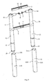
FIG.1 is a perspective view of the extending ladder in accordance with an exemplary embodiment of the present invention. -
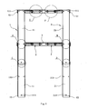
FIG.2 is the sectional view of the extending ladder ofFIG. 1 . -
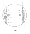
FIG.3 is an enlarged view of region A in theFIG.2 . -
FIG. 4 is an enlarged view of region B in theFIG.2 . -
FIG. 5 is an enlarged view of region C in theFIG.2 -
FIG.6 is an enlarged view of region D in theFIG.2 . -
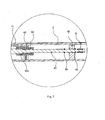
FIG.7 is an enlarged view of region E in theFIG.2 . -
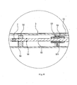
FIG.8 is an enlarged view of region F in theFIG.2 . -
FIG.9 is an exposure view of the embodiment in accordance with an exemplary embodiment of the present invention. -
FIG.10 is a diagrammatic depiction of the embodiment in accordance with the embodiment of the present invention showing the installation manner of the limiting annulation and the bushing on the column. - To enable a further understanding of the innovative and technological content of the invention herein, refer to the detailed description of the invention and the accompanying drawings below:
-
FIGS. 1∼18 show a preferable embodiment of the present invention. - In this embodiment, the extending ladder comprises:
- a left stile 1 and a
right stile 2 which disposed oppositely; and - a plurality of
rungs 3 each extending between the left stile 1 and theright stile 2. - The left stile 1 is formed of telescopically collapsible
left columns 11 which are disposed orderly in a nested arrangement for relative lengthwise movement in a telescopic fashion. Theright stile 2 is also formed of telescopically collapsibleright columns 21 which are disposed orderly in a nested arrangement for relative lengthwise movement in a telescopic fashion. Theleft columns 11 and theright columns 21 are in rough tubular shape. - Each
rung 3 is mounted between the opposite twocolumns rung 3 is hollow and in rectangular figure. Aleft latch mechanism 4 is disposed in eachrung 3 for locking the upperleft column 11 with thecorresponding rung 3 when the ladder extending lengthwise, to keep the ladder from collapsing. Aright latch mechanism 5 is disposed in eachrung 3 for locking the upperright column 21 with thecorresponding rung 3 when the ladder extending lengthwise, to keep the ladder from collapsing. Theleft latch mechanism 4 and theright latch mechanism 5 are respectively provided with aleft button 6 and aright button 7 to operate the corresponding latch mechanism. - As shown in
FIG. 3 andFIG.7 , theleft latch mechanism 4 also comprises: - a
left pin 41 coupled to the left end of eachrung 3, which makes therung 3 be connected with the upper part of the correspondingleft column 11; - a
left pin 42 disposed in eachrung 3, which can move horizontally and transversely relatively to thecorresponding rung 3 and can stick out of the left side of thecorresponding rung 3; - a
first spring 43 disposed out of theleft pin 42 to ensure theleft pin 42 have a trend of sticking out of the left side of therung 3; - a
first spring seat 44 is provided on the left side of the interior of therung 3, which theleft pin 42 can movably pass through, thefirst spring 43 is disposed in thefirst spring seat 44 with one end against the inner wall of the right side of thefirst spring seat 44 and the other end against ashoulder 421 protruded at the middle of theleft pin 42; and - a left limiting
block 45 is provided on the left side of the interior of therung 3, which theleft pin 42 can movably pass through, and two stop rings 46 are provided on theleft pin 42 in distance, which respectively locates at two sides of theleft limiting block 45 and can respectively be stopped by the surface of two sides of theleft limiting block 45; theleft button 6 is connected with theleft pin 42, correspondingly, a first locking holes 111 is provided on the top of theleft column 11 for the correspondingleft pin 42 to pass through, and a second locking holes 112 is provided on the middle of theleft column 11 for the correspondingleft pin 42 to insert into theleft column 11. - As shown in
FIG. 4 andFIG.8 , theright latch mechanism 5 also comprises: - a
right connector 51 is coupled to the right end of eachrung 3, which makes therung 3 be connected with the upper part of the correspondingright column 21; - a
right pin 52 is disposed in eachrung 3, which can move horizontally and transversely relatively to thecorresponding rung 3 and can stick out of the right side of thecorresponding rung 3; - a
second spring 53 is disposed out of theright pin 52 to ensure theright pin 52 have a trend of sticking out of the right side of therung 3; - a
second spring seat 54 is provided on the right side of the interior of therung 3, which theright pin 52 can movably pass through, thesecond spring 53 is disposed in thesecond spring seat 54 with one end against the inner wall of the left side of thesecond spring seat 54 and the other end against ashoulder 521 protruded at the middle of theright pin 52; and - a
right limiting block 55 is provided on the right side of the interior of therung 3, which theright pin 52 can movably pass through, and two stop rings 56 are provided on theright pin 52 in distance, which respectively locates at two sides of theright limiting block 55 and can respectively be stopped by the surface of two sides of theright limiting block 55; theright button 7 is connected with theright pin 52, correspondingly, a third locking holes 211 is provided on the top of theright column 21 for the correspondingright pin 52 to pass through, and a fourth locking holes 212 is provided on the middle of theright column 21 for the correspondingright pin 52 to insert into theright column 21. - The
left button 6 and theright button 7 are disposed closely with each other in the middle of thecorresponding rung 3. That is, aleft groove 31 and aright groove 32 are provided in the middle of therung 3 respectively for theleft button 6 and theright button 7 to pass though, theleft button 6 and theright button 7 are respectively limited in theleft groove 31 and theright groove 32 and can move breadthwise respectively relatively to theleft groove 31 and theright groove 32. It makes twobuttons rung 3 released from the correspondingcolumn 11; 21. The right side of theleft button 6 is provided with a resistingportion 61, which is convenient for the fingertip to resist against, and the left side of theright button 7 is also provided with a resistingportion 71 which is convenient for the fingertip to resist against. - A left limiting
annulation 8 is mounted around of the periphery surface of the middle of theleft column 11, which is sandwiched between two adjacentleft columns 11, correspondingly, theleft connector 41 is provided with an annular wall to form asocket 411 which is preferably dimensioned to tightly connect with the periphery of the top of theleft column 11, aninner shoulder 412 protruding inward is formed on the top of the inner wall of thesocket 411 to stop theleft limiting annulation 8, and theleft connector 41 is also provided with a throughhole 413 communicating with thesocket 411 for theleft pin 42 to pass through. - The
left limiting annulation 8 is provided with afirst gap 81 opposite to thefirst locking hole 111, and the inner wall of the left limitingannulation 8 is provided with a plurality ofprotrusions 82, correspondingly, the peripheral of the middle of theleft column 11 is provided with a plurality ofsmall holes 113 for the correspondingprotrusion 82 to insert. - While a
right limiting annulation 9 is mounted around of the periphery surface of the middle of theright column 21, which is sandwiched between two adjacentright columns 21, correspondingly, theright connector 51 is provided with an annular wall to form asocket 511 which is preferably dimensioned to tightly connect with the periphery of the top of theright column 21, aninner shoulder 512 protruding inward is formed on the top of the inner wall of thesocket 511 to stop theright limiting annulation 9, and theright connector 51 is also provided with a throughhole 513 communicating with thesocket 511 for theright pin 52 to pass through. - The
right limiting annulation 9 is provided with asecond gap 91 opposite to thethird locking hole 211, and the inner wall of theright limiting annulation 9 is provided with a plurality ofprotrusions 92, correspondingly, the peripheral of the middle of theright column 21 is provided with a plurality ofsmall holes 213 for the correspondingprotrusion 92 to insert. - As shown in
FIG.9 andFIG.10 , aleft bushing 10 is mounted around the opening of the bottom of theleft column 11, theexterior surface 101 of the upper part of theleft bushing 10 is in contact with the inner wall of the next lowerleft column 11, and theexterior surface 102 of the lower part of theleft bushing 10 is tapered. - The internal surface of the upper part of the
left bushing 10 is provided with a plurality ofprojects 103, correspondingly, the peripheral of the bottom of theleft column 11 is provided with a plurality oflocation holes 114 for thecorresponding project 103 to insert. - While a
right bushing 12 is mounted around the opening of the bottom of theright column 21, theexterior surface 122 of the upper part of theright bushing 12 is in contact with the inner wall of the next lowerright column 21, and theexterior surface 122 of the lower part of theright bushing 12 is tapered. - The internal surface of the upper part of the
right bushing 12 is provided with a plurality ofprojects 123, correspondingly, the peripheral of the bottom of theright column 21 is provided with a plurality oflocation holes 214 for thecorresponding project 123 to insert. - The operating principle and process of the embodiment of the present invention is as follows:
- Here, only the action process of a working unit, which is composed of the
left column 11, theright column 21, therung 3 between twocolumns columns - The locking process of the right column 21:
- After the
right column 21 is pulled upward to be in position, theright limiting annulation 9 will be stopped by the matchedinner shoulder 512 on theright connector 51, then theright column 21 is prevented from being pulling out further. Moreover, as theright limiting annulation 9 is stopped by the correspondinginner shoulder 512, it will indicate that theright column 21 has been in right position and the user should stop pulling. At this moment, the fourth locking holes 212 on the middle of the pulledright column 21 and the third locking holes 211 on the top of the next lowerright column 21 both locate on the same axis. Therefore, under the function of thesecond spring 53, theright pin 52 locating in therung 3 adjacent to the next lowerright column 21 will be ejected out, and pass orderly through the throughhole 513 on theright connector 51 and thethird locking hole 211, then insert into thefourth locking hole 212, to lock therung 3 and the upperright column 21. While therung 3 is fixed with the otherright column 21, accordingly, therung 3, theright column 21 connected with therung 3 and the upperright column 21 are interlocked with each other. - The locking process of the
left column 11 is the same as theright column 21, and both processes are acting simultaneity. - The locking process of the
right column 21 and the left column 11: - The user opens the thumb and the index finger of one (same) hand, taking the left hand as an example, the thumb touches the
right button 7 and the index finger touches theleft button 6, then, two fingers drives the left and right buttons respectively to move closely and closely with inward force at the same time, to make the left andright pin right pin 42 will respectively break away from thesecond locking hole 112 and thefourth locking hole 212 on the uppercorresponding column rung 3 from the upper left andright column - When the upper left and
right column right bushing right bushing right column right column
Claims (7)
- An extending ladder comprising:a left stile (1) and a right stile (2) which are disposed oppositely;a plurality of rungs (3) each extending between the left (1) stile and the right stile (2);the left stile (1) being formed of telescopically collapsible left columns (11) which are disposed orderly in a nested arrangement;the right stile (2) being formed of telescopically collapsible right columns (21) which are disposed orderly in a nested arrangement;and each rung (3) being mounted between the opposite two columns (11, 21);a left latch mechanism (4) disposed in each rung (3) for locking the upper left column (11) with the corresponding rung (3) when the ladder extending lengthwise, to keep the ladder from collapsing;a right latch mechanism (5) disposed in each rung (3) for locking the upper right column (21) with the corresponding rung (3) when the ladder extending lengthwise, to keep the ladder from collapsing;the left latch mechanism (4) and right latch mechanism (5) being respectively provided with a left button (6) and a right button (7) to operate the corresponding latch mechanism;wherein the left button (6) and the right button (7) are disposed closely with each other in the middle of each rung (3), so as to make two buttons (6, 7) be operated conveniently by single hand to make the rung (3) released from the corresponding column (11; 21). and wherein the left latch mechanism (4) also comprises:a left connector (41) coupled to the left end of each rung (3), which makes the rung (3) be connected with the upper part of the corresponding left column (11);a left pin (42) disposed in each rung (3), which can move horizontally and transversely relatively to the corresponding rung (3) and can stick out of the left side of the corresponding rung (3);the left button (6) being connected with the left pin (42), correspondingly, a first locking hole (111) being provided on the top of the left column (11) for the corresponding left pin (42) to pass through, and a second locking hole (112) being provided on the middle of the left column (11) for the corresponding left pin (42) to insert into the left column (11);while the right latch mechanism (5) also comprises:a right connector (41) coupled to the right end of each rung (3), which makes the rung (3) be connected with the upper part of the corresponding right column (21);
and a right pin (52) disposed in each rung (3), which can move horizontally and
transversely relatively to the corresponding rung (3) and can stick out of the right side of the corresponding rung (3);the right button (7) being connected with the right pin (52), correspondingly, a third
locking hole (211) being provided on the top of the right column (21) for the corresponding right pin (52) to pass through, and a fourth locking hole (212) provided on the middle of the right column (211) for the corresponding right pin (52) to insert into the right column (21), characterized in that the left latch mechanism further comprises a first spring (43) disposed out of the left pin (42) to ensure the left pin (42) have a trend of sticking out of the left side of the rung (3); and the right latch mechanism further comprises a second spring (53) disposed out of the right pin (52) to ensure the right pin (52) have a trend of sticking out of the right side of the rung (3): and in that a left limiting block (45) is provided on the left side of the interior of the rung (3), which the left pin (42) can movably pass through, and two stop rings (46) are provided on the left pin (42) in distance, which respectively locate at two sides of the left limiting block (45) and can respectively be stopped by the surface of two sides of the left limiting block (45); while a right limiting block (55) is provided on the right side of the interior of the rung (3), which the right pin (52) can movably pass through, and two stop rings (56) are provided on the right pin (52) in distance, which respectively locate at two sides of the right limiting block (55) and can respectively be stopped by the surface of two sides of the right limiting block (55). - The extending ladder of claim 1, wherein a first spring seat (44) is provided on the left side of the interior of the rung (3), which the left pin (42) can movably pass through, the first spring (43) is disposed in the first spring seat (44) with one end against the inner wall of the right side of the first spring seat (44) and the other end against a shoulder (421) protruded at the middle of the left pin (42);
while a second spring seat (54) is provided on the right side of the interior of the rung (3),
which the right pin (52) can movably pass through, the second spring (53) is disposed in the second spring seat (54) with one end against the inner wall of the left side of the second spring seat (54) and the other end against a shoulder (521) protruded at the middle of the right pin (52). - The extending ladder of claim 1, wherein a left limiting annulation (8) is mounted around of the periphery surface of the middle of the left column (11), which is sandwiched between two adjacent left columns (11), correspondingly, the left connector (41) is provided with an annular wall to form a socket (411) which is preferably dimensioned to tightly connect with the periphery of the top of the left column (11), an inner shoulder (412) protruding inward is formed on the top of the inner wall of the socket (411) to stop the left limiting annulation (8), and the left connector (41) is also provided with a through hole (413) communicating with the socket (411) for the left pin (42) to pass through;
while a right limiting annulation (9) is mounted around of the periphery surface of the middle of the right column (21), which is sandwiched between two adjacent right columns (21), correspondingly, the right connector (51) is provided with an annular wall to form a socket (511) which is preferably dimensioned to tightly connect with the periphery of the top of the right column (21), an inner shoulder (512) protruding inward is formed on the top of the inner wall of the socket (511) to stop the right limiting annulation (9), and the right connector (51) is also provided with a through hole (513) communicating with the socket (511) for the right pin (52) to pass through. - The extending ladder of claim 3, wherein the left limiting annulation (8) is provided with a first gap (81) opposite to the first locking hole (111), and the inner wall of the left limiting annulation (8) is provided with a plurality of protrusions (82), correspondingly, the peripheral of the middle of the left column (11) is provided with a plurality of small holes (113) for the corresponding protrusion (82) to insert;
while the right limiting annulation (9) is provided with a second gap (91) opposite to the third locking hole (211), and the inner wall of the right limiting annulation (9) is provided with a plurality of protrusions (92), correspondingly, the peripheral of the middle of the right column (21) is provided with a plurality of small holes (213) for the corresponding protrusion (92) to insert. - The extending ladder of any preceding claim, wherein a left bushing (10) is mounted around the opening of the bottom of the left column (11), the exterior surface (101) of the upper part of the left bushing (10) is in contact with the inner wall of the next lower left column (11), and the exterior surface (102) of the lower part of the left bushing (10) is tapered;
while a right bushing (12) is mounted around the opening of the bottom of the right column (21), the exterior surface (122) of the upper part of the right bushing (12) is in contact with the inner wall of the next lower right column (21), and the exterior surface (122) of the lower part of the right bushing (12) is tapered. - The extending ladder of claim 5, wherein the internal surface of the upper part of the left bushing (10) is provided with a plurality of projects (103), correspondingly, the peripheral of the bottom of the left column (11) is provided with a plurality of location holes (114) for the corresponding project (103) to insert
while the internal surface of the upper part of the right bushing (12) is provided with a plurality of projects (123), correspondingly, the peripheral of the bottom of the right column (21) is provided with a plurality of location holes (214) for the corresponding project (123) to insert. - The extending ladder of claim 1, wherein the right side of the left button (6) is provided with a resisting portion (61) which is convenient for the fingertip to resist against, and the left side of the right button (7) is also provided with a resisting portion (71) which is convenient for the fingertip to resist against.
Applications Claiming Priority (2)
| Application Number | Priority Date | Filing Date | Title |
|---|---|---|---|
| CNU2008201627852U CN201250602Y (en) | 2008-08-14 | 2008-08-14 | Extension ladder |
| PCT/CN2009/000792 WO2010017684A1 (en) | 2008-08-14 | 2009-07-14 | Extending ladder |
Publications (3)
| Publication Number | Publication Date |
|---|---|
| EP2322752A1 EP2322752A1 (en) | 2011-05-18 |
| EP2322752A4 EP2322752A4 (en) | 2012-09-12 |
| EP2322752B1 true EP2322752B1 (en) | 2013-05-29 |
Family
ID=40746276
Family Applications (1)
| Application Number | Title | Priority Date | Filing Date |
|---|---|---|---|
| EP09806287.0A Not-in-force EP2322752B1 (en) | 2008-08-14 | 2009-07-14 | Extending ladder |
Country Status (4)
| Country | Link |
|---|---|
| EP (1) | EP2322752B1 (en) |
| CN (1) | CN201250602Y (en) |
| DK (1) | DK2322752T3 (en) |
| WO (1) | WO2010017684A1 (en) |
Families Citing this family (4)
| Publication number | Priority date | Publication date | Assignee | Title |
|---|---|---|---|---|
| CN101338649B (en) * | 2008-08-14 | 2011-02-09 | 王万兴 | Telescopic ladder |
| CN201250602Y (en) * | 2008-08-14 | 2009-06-03 | 王万兴 | Extension ladder |
| JP5897935B2 (en) * | 2012-03-02 | 2016-04-06 | アルインコ株式会社 | Telescopic leg locking device for workbench |
| WO2018081786A1 (en) * | 2016-10-31 | 2018-05-03 | Horizon Global Americas Inc. | Telescoping ramp |
Family Cites Families (12)
| Publication number | Priority date | Publication date | Assignee | Title |
|---|---|---|---|---|
| US1712942A (en) * | 1927-12-29 | 1929-05-14 | Hiram K Smith | Collapsible ladder |
| GB8717884D0 (en) * | 1987-07-28 | 1987-09-03 | Baker M R E | Folding ladders |
| EP0527766B1 (en) | 1990-04-10 | 1996-06-05 | Bertschi, Bruno | Collapsible ladder |
| GB9403863D0 (en) * | 1994-03-01 | 1994-04-20 | Foxdale Dev Ltd | Extensible ladder |
| US6708800B2 (en) | 2002-08-02 | 2004-03-23 | Core Distribution, Inc. | Extending ladder and associated manufacturing methods |
| CN2881052Y (en) * | 2006-02-08 | 2007-03-21 | 何海涛 | Telescopic ladder |
| GB2436584B (en) * | 2006-03-30 | 2011-08-31 | Norman William Liefke | An extension ladder with improved mechanism |
| US7967110B2 (en) * | 2006-07-27 | 2011-06-28 | Werner Co. | Tubular access ladder and method |
| CN200971751Y (en) * | 2006-10-30 | 2007-11-07 | 范刚 | Locking device for telescopic lalder |
| CN200985738Y (en) * | 2006-11-27 | 2007-12-05 | 苏正平 | Telescopic ladder |
| CN201047247Y (en) * | 2007-04-23 | 2008-04-16 | 简世坤 | Telescopic ladder |
| CN201250602Y (en) * | 2008-08-14 | 2009-06-03 | 王万兴 | Extension ladder |
-
2008
- 2008-08-14 CN CNU2008201627852U patent/CN201250602Y/en not_active Expired - Lifetime
-
2009
- 2009-07-14 WO PCT/CN2009/000792 patent/WO2010017684A1/en not_active Ceased
- 2009-07-14 EP EP09806287.0A patent/EP2322752B1/en not_active Not-in-force
- 2009-07-14 DK DK09806287.0T patent/DK2322752T3/en active
Also Published As
| Publication number | Publication date |
|---|---|
| EP2322752A1 (en) | 2011-05-18 |
| WO2010017684A1 (en) | 2010-02-18 |
| DK2322752T3 (en) | 2013-08-26 |
| CN201250602Y (en) | 2009-06-03 |
| EP2322752A4 (en) | 2012-09-12 |
Similar Documents
| Publication | Publication Date | Title |
|---|---|---|
| EP3581754B1 (en) | Telescopic ladder assembly | |
| EP1402143B2 (en) | Collapsible Ladder | |
| CA3044940C (en) | Collapsible ladder | |
| EP2322752A1 (en) | Extending ladder | |
| WO2014000407A1 (en) | Safe telescopic ladder capable of preventing hand from being pinched | |
| JP7074324B2 (en) | Ladder body telescopic leg device | |
| WO2014139940A1 (en) | Collapsible ladder | |
| JP2023018147A (en) | Extendable leg device of ladder body | |
| US8939256B2 (en) | Collapsible ladder | |
| EP3211174A1 (en) | Telescoping ladder with a cascading collapse mechanism | |
| JP7462364B1 (en) | Telescopic leg device and ladder body | |
| US20130175119A1 (en) | Collapsible ladder | |
| CN201339429Y (en) | Folding telescopic ladder convenient and safe to fold | |
| CN200985738Y (en) | Telescopic ladder | |
| JP3129436U (en) | Multi-point telescopic stepladder and ladder | |
| CN209395852U (en) | A kind of locking structure and unlocking structure of the release tab of perambulator | |
| JP6255230B2 (en) | Stepladder platform | |
| JP2023068359A (en) | Locking device of leg body in work bench |
Legal Events
| Date | Code | Title | Description |
|---|---|---|---|
| PUAI | Public reference made under article 153(3) epc to a published international application that has entered the european phase |
Free format text: ORIGINAL CODE: 0009012 |
|
| 17P | Request for examination filed |
Effective date: 20110214 |
|
| AK | Designated contracting states |
Kind code of ref document: A1 Designated state(s): AT BE BG CH CY CZ DE DK EE ES FI FR GB GR HR HU IE IS IT LI LT LU LV MC MK MT NL NO PL PT RO SE SI SK SM TR |
|
| AX | Request for extension of the european patent |
Extension state: AL BA RS |
|
| DAX | Request for extension of the european patent (deleted) | ||
| A4 | Supplementary search report drawn up and despatched |
Effective date: 20120816 |
|
| RIC1 | Information provided on ipc code assigned before grant |
Ipc: E06C 7/06 20060101ALI20120809BHEP Ipc: E06C 1/12 20060101AFI20120809BHEP |
|
| GRAP | Despatch of communication of intention to grant a patent |
Free format text: ORIGINAL CODE: EPIDOSNIGR1 |
|
| GRAS | Grant fee paid |
Free format text: ORIGINAL CODE: EPIDOSNIGR3 |
|
| GRAA | (expected) grant |
Free format text: ORIGINAL CODE: 0009210 |
|
| AK | Designated contracting states |
Kind code of ref document: B1 Designated state(s): AT BE BG CH CY CZ DE DK EE ES FI FR GB GR HR HU IE IS IT LI LT LU LV MC MK MT NL NO PL PT RO SE SI SK SM TR |
|
| REG | Reference to a national code |
Ref country code: GB Ref legal event code: FG4D |
|
| REG | Reference to a national code |
Ref country code: CH Ref legal event code: EP |
|
| REG | Reference to a national code |
Ref country code: AT Ref legal event code: REF Ref document number: 614528 Country of ref document: AT Kind code of ref document: T Effective date: 20130615 |
|
| REG | Reference to a national code |
Ref country code: IE Ref legal event code: FG4D |
|
| REG | Reference to a national code |
Ref country code: DE Ref legal event code: R096 Ref document number: 602009016117 Country of ref document: DE Effective date: 20130725 |
|
| REG | Reference to a national code |
Ref country code: CH Ref legal event code: NV Representative=s name: MARKS AND CLERK (LUXEMBOURG) LLP, CH |
|
| REG | Reference to a national code |
Ref country code: DK Ref legal event code: T3 |
|
| REG | Reference to a national code |
Ref country code: NL Ref legal event code: T3 |
|
| REG | Reference to a national code |
Ref country code: LT Ref legal event code: MG4D |
|
| PG25 | Lapsed in a contracting state [announced via postgrant information from national office to epo] |
Ref country code: NO Free format text: LAPSE BECAUSE OF FAILURE TO SUBMIT A TRANSLATION OF THE DESCRIPTION OR TO PAY THE FEE WITHIN THE PRESCRIBED TIME-LIMIT Effective date: 20130829 Ref country code: SI Free format text: LAPSE BECAUSE OF FAILURE TO SUBMIT A TRANSLATION OF THE DESCRIPTION OR TO PAY THE FEE WITHIN THE PRESCRIBED TIME-LIMIT Effective date: 20130529 Ref country code: LT Free format text: LAPSE BECAUSE OF FAILURE TO SUBMIT A TRANSLATION OF THE DESCRIPTION OR TO PAY THE FEE WITHIN THE PRESCRIBED TIME-LIMIT Effective date: 20130529 Ref country code: IS Free format text: LAPSE BECAUSE OF FAILURE TO SUBMIT A TRANSLATION OF THE DESCRIPTION OR TO PAY THE FEE WITHIN THE PRESCRIBED TIME-LIMIT Effective date: 20130929 Ref country code: PT Free format text: LAPSE BECAUSE OF FAILURE TO SUBMIT A TRANSLATION OF THE DESCRIPTION OR TO PAY THE FEE WITHIN THE PRESCRIBED TIME-LIMIT Effective date: 20130930 Ref country code: FI Free format text: LAPSE BECAUSE OF FAILURE TO SUBMIT A TRANSLATION OF THE DESCRIPTION OR TO PAY THE FEE WITHIN THE PRESCRIBED TIME-LIMIT Effective date: 20130529 Ref country code: GR Free format text: LAPSE BECAUSE OF FAILURE TO SUBMIT A TRANSLATION OF THE DESCRIPTION OR TO PAY THE FEE WITHIN THE PRESCRIBED TIME-LIMIT Effective date: 20130830 Ref country code: ES Free format text: LAPSE BECAUSE OF FAILURE TO SUBMIT A TRANSLATION OF THE DESCRIPTION OR TO PAY THE FEE WITHIN THE PRESCRIBED TIME-LIMIT Effective date: 20130909 Ref country code: SE Free format text: LAPSE BECAUSE OF FAILURE TO SUBMIT A TRANSLATION OF THE DESCRIPTION OR TO PAY THE FEE WITHIN THE PRESCRIBED TIME-LIMIT Effective date: 20130529 |
|
| PG25 | Lapsed in a contracting state [announced via postgrant information from national office to epo] |
Ref country code: BG Free format text: LAPSE BECAUSE OF FAILURE TO SUBMIT A TRANSLATION OF THE DESCRIPTION OR TO PAY THE FEE WITHIN THE PRESCRIBED TIME-LIMIT Effective date: 20130829 Ref country code: HR Free format text: LAPSE BECAUSE OF FAILURE TO SUBMIT A TRANSLATION OF THE DESCRIPTION OR TO PAY THE FEE WITHIN THE PRESCRIBED TIME-LIMIT Effective date: 20130529 Ref country code: PL Free format text: LAPSE BECAUSE OF FAILURE TO SUBMIT A TRANSLATION OF THE DESCRIPTION OR TO PAY THE FEE WITHIN THE PRESCRIBED TIME-LIMIT Effective date: 20130529 |
|
| PG25 | Lapsed in a contracting state [announced via postgrant information from national office to epo] |
Ref country code: LV Free format text: LAPSE BECAUSE OF FAILURE TO SUBMIT A TRANSLATION OF THE DESCRIPTION OR TO PAY THE FEE WITHIN THE PRESCRIBED TIME-LIMIT Effective date: 20130529 |
|
| PG25 | Lapsed in a contracting state [announced via postgrant information from national office to epo] |
Ref country code: SK Free format text: LAPSE BECAUSE OF FAILURE TO SUBMIT A TRANSLATION OF THE DESCRIPTION OR TO PAY THE FEE WITHIN THE PRESCRIBED TIME-LIMIT Effective date: 20130529 Ref country code: EE Free format text: LAPSE BECAUSE OF FAILURE TO SUBMIT A TRANSLATION OF THE DESCRIPTION OR TO PAY THE FEE WITHIN THE PRESCRIBED TIME-LIMIT Effective date: 20130529 Ref country code: CZ Free format text: LAPSE BECAUSE OF FAILURE TO SUBMIT A TRANSLATION OF THE DESCRIPTION OR TO PAY THE FEE WITHIN THE PRESCRIBED TIME-LIMIT Effective date: 20130529 |
|
| PG25 | Lapsed in a contracting state [announced via postgrant information from national office to epo] |
Ref country code: MC Free format text: LAPSE BECAUSE OF FAILURE TO SUBMIT A TRANSLATION OF THE DESCRIPTION OR TO PAY THE FEE WITHIN THE PRESCRIBED TIME-LIMIT Effective date: 20130529 Ref country code: IT Free format text: LAPSE BECAUSE OF FAILURE TO SUBMIT A TRANSLATION OF THE DESCRIPTION OR TO PAY THE FEE WITHIN THE PRESCRIBED TIME-LIMIT Effective date: 20130529 Ref country code: RO Free format text: LAPSE BECAUSE OF FAILURE TO SUBMIT A TRANSLATION OF THE DESCRIPTION OR TO PAY THE FEE WITHIN THE PRESCRIBED TIME-LIMIT Effective date: 20130529 |
|
| PLBE | No opposition filed within time limit |
Free format text: ORIGINAL CODE: 0009261 |
|
| STAA | Information on the status of an ep patent application or granted ep patent |
Free format text: STATUS: NO OPPOSITION FILED WITHIN TIME LIMIT |
|
| REG | Reference to a national code |
Ref country code: IE Ref legal event code: MM4A |
|
| 26N | No opposition filed |
Effective date: 20140303 |
|
| REG | Reference to a national code |
Ref country code: DE Ref legal event code: R097 Ref document number: 602009016117 Country of ref document: DE Effective date: 20140303 |
|
| PG25 | Lapsed in a contracting state [announced via postgrant information from national office to epo] |
Ref country code: IE Free format text: LAPSE BECAUSE OF NON-PAYMENT OF DUE FEES Effective date: 20130714 |
|
| PGFP | Annual fee paid to national office [announced via postgrant information from national office to epo] |
Ref country code: NL Payment date: 20140710 Year of fee payment: 6 Ref country code: CH Payment date: 20140714 Year of fee payment: 6 Ref country code: DK Payment date: 20140710 Year of fee payment: 6 |
|
| PGFP | Annual fee paid to national office [announced via postgrant information from national office to epo] |
Ref country code: AT Payment date: 20140710 Year of fee payment: 6 |
|
| PGFP | Annual fee paid to national office [announced via postgrant information from national office to epo] |
Ref country code: BE Payment date: 20140714 Year of fee payment: 6 |
|
| PG25 | Lapsed in a contracting state [announced via postgrant information from national office to epo] |
Ref country code: SM Free format text: LAPSE BECAUSE OF FAILURE TO SUBMIT A TRANSLATION OF THE DESCRIPTION OR TO PAY THE FEE WITHIN THE PRESCRIBED TIME-LIMIT Effective date: 20130529 |
|
| PG25 | Lapsed in a contracting state [announced via postgrant information from national office to epo] |
Ref country code: CY Free format text: LAPSE BECAUSE OF FAILURE TO SUBMIT A TRANSLATION OF THE DESCRIPTION OR TO PAY THE FEE WITHIN THE PRESCRIBED TIME-LIMIT Effective date: 20130529 Ref country code: MT Free format text: LAPSE BECAUSE OF FAILURE TO SUBMIT A TRANSLATION OF THE DESCRIPTION OR TO PAY THE FEE WITHIN THE PRESCRIBED TIME-LIMIT Effective date: 20130529 Ref country code: TR Free format text: LAPSE BECAUSE OF FAILURE TO SUBMIT A TRANSLATION OF THE DESCRIPTION OR TO PAY THE FEE WITHIN THE PRESCRIBED TIME-LIMIT Effective date: 20130529 |
|
| PG25 | Lapsed in a contracting state [announced via postgrant information from national office to epo] |
Ref country code: LU Free format text: LAPSE BECAUSE OF NON-PAYMENT OF DUE FEES Effective date: 20130714 Ref country code: HU Free format text: LAPSE BECAUSE OF FAILURE TO SUBMIT A TRANSLATION OF THE DESCRIPTION OR TO PAY THE FEE WITHIN THE PRESCRIBED TIME-LIMIT; INVALID AB INITIO Effective date: 20090714 Ref country code: MK Free format text: LAPSE BECAUSE OF FAILURE TO SUBMIT A TRANSLATION OF THE DESCRIPTION OR TO PAY THE FEE WITHIN THE PRESCRIBED TIME-LIMIT Effective date: 20130529 |
|
| REG | Reference to a national code |
Ref country code: DK Ref legal event code: EBP Effective date: 20150731 |
|
| REG | Reference to a national code |
Ref country code: CH Ref legal event code: PL |
|
| REG | Reference to a national code |
Ref country code: AT Ref legal event code: MM01 Ref document number: 614528 Country of ref document: AT Kind code of ref document: T Effective date: 20150714 |
|
| REG | Reference to a national code |
Ref country code: NL Ref legal event code: MM Effective date: 20150801 |
|
| PG25 | Lapsed in a contracting state [announced via postgrant information from national office to epo] |
Ref country code: CH Free format text: LAPSE BECAUSE OF NON-PAYMENT OF DUE FEES Effective date: 20150731 Ref country code: LI Free format text: LAPSE BECAUSE OF NON-PAYMENT OF DUE FEES Effective date: 20150731 |
|
| PG25 | Lapsed in a contracting state [announced via postgrant information from national office to epo] |
Ref country code: AT Free format text: LAPSE BECAUSE OF NON-PAYMENT OF DUE FEES Effective date: 20150714 Ref country code: NL Free format text: LAPSE BECAUSE OF NON-PAYMENT OF DUE FEES Effective date: 20150801 |
|
| REG | Reference to a national code |
Ref country code: FR Ref legal event code: PLFP Year of fee payment: 8 |
|
| PG25 | Lapsed in a contracting state [announced via postgrant information from national office to epo] |
Ref country code: DK Free format text: LAPSE BECAUSE OF NON-PAYMENT OF DUE FEES Effective date: 20150731 |
|
| REG | Reference to a national code |
Ref country code: FR Ref legal event code: PLFP Year of fee payment: 9 |
|
| PG25 | Lapsed in a contracting state [announced via postgrant information from national office to epo] |
Ref country code: BE Free format text: LAPSE BECAUSE OF NON-PAYMENT OF DUE FEES Effective date: 20150731 |
|
| REG | Reference to a national code |
Ref country code: FR Ref legal event code: PLFP Year of fee payment: 10 |
|
| PGFP | Annual fee paid to national office [announced via postgrant information from national office to epo] |
Ref country code: GB Payment date: 20230629 Year of fee payment: 15 |
|
| PGFP | Annual fee paid to national office [announced via postgrant information from national office to epo] |
Ref country code: FR Payment date: 20230703 Year of fee payment: 15 Ref country code: DE Payment date: 20230703 Year of fee payment: 15 |
|
| REG | Reference to a national code |
Ref country code: DE Ref legal event code: R119 Ref document number: 602009016117 Country of ref document: DE |
|
| GBPC | Gb: european patent ceased through non-payment of renewal fee |
Effective date: 20240714 |
|
| PG25 | Lapsed in a contracting state [announced via postgrant information from national office to epo] |
Ref country code: DE Free format text: LAPSE BECAUSE OF NON-PAYMENT OF DUE FEES Effective date: 20250201 |
|
| PG25 | Lapsed in a contracting state [announced via postgrant information from national office to epo] |
Ref country code: FR Free format text: LAPSE BECAUSE OF NON-PAYMENT OF DUE FEES Effective date: 20240731 |
|
| PG25 | Lapsed in a contracting state [announced via postgrant information from national office to epo] |
Ref country code: GB Free format text: LAPSE BECAUSE OF NON-PAYMENT OF DUE FEES Effective date: 20240714 |