EP2322390A1 - Knee airbag device for vehicle - Google Patents
Knee airbag device for vehicle Download PDFInfo
- Publication number
- EP2322390A1 EP2322390A1 EP09811496A EP09811496A EP2322390A1 EP 2322390 A1 EP2322390 A1 EP 2322390A1 EP 09811496 A EP09811496 A EP 09811496A EP 09811496 A EP09811496 A EP 09811496A EP 2322390 A1 EP2322390 A1 EP 2322390A1
- Authority
- EP
- European Patent Office
- Prior art keywords
- portions
- vehicle
- tear
- lateral direction
- knee airbag
- Prior art date
- Legal status (The legal status is an assumption and is not a legal conclusion. Google has not performed a legal analysis and makes no representation as to the accuracy of the status listed.)
- Granted
Links
Images


Classifications
-
- B—PERFORMING OPERATIONS; TRANSPORTING
- B60—VEHICLES IN GENERAL
- B60R—VEHICLES, VEHICLE FITTINGS, OR VEHICLE PARTS, NOT OTHERWISE PROVIDED FOR
- B60R21/00—Arrangements or fittings on vehicles for protecting or preventing injuries to occupants or pedestrians in case of accidents or other traffic risks
- B60R21/02—Occupant safety arrangements or fittings, e.g. crash pads
- B60R21/16—Inflatable occupant restraints or confinements designed to inflate upon impact or impending impact, e.g. air bags
- B60R21/20—Arrangements for storing inflatable members in their non-use or deflated condition; Arrangement or mounting of air bag modules or components
- B60R21/205—Arrangements for storing inflatable members in their non-use or deflated condition; Arrangement or mounting of air bag modules or components in dashboards
- B60R21/206—Arrangements for storing inflatable members in their non-use or deflated condition; Arrangement or mounting of air bag modules or components in dashboards in the lower part of dashboards, e.g. for protecting the knees
-
- B—PERFORMING OPERATIONS; TRANSPORTING
- B60—VEHICLES IN GENERAL
- B60R—VEHICLES, VEHICLE FITTINGS, OR VEHICLE PARTS, NOT OTHERWISE PROVIDED FOR
- B60R21/00—Arrangements or fittings on vehicles for protecting or preventing injuries to occupants or pedestrians in case of accidents or other traffic risks
- B60R21/02—Occupant safety arrangements or fittings, e.g. crash pads
- B60R21/16—Inflatable occupant restraints or confinements designed to inflate upon impact or impending impact, e.g. air bags
- B60R21/20—Arrangements for storing inflatable members in their non-use or deflated condition; Arrangement or mounting of air bag modules or components
- B60R21/215—Arrangements for storing inflatable members in their non-use or deflated condition; Arrangement or mounting of air bag modules or components characterised by the covers for the inflatable member
- B60R21/2165—Arrangements for storing inflatable members in their non-use or deflated condition; Arrangement or mounting of air bag modules or components characterised by the covers for the inflatable member characterised by a tear line for defining a deployment opening
Definitions
- the present invention relates to a knee airbag device for a vehicle that protects the knees of a vehicle occupant.
- an airbag module is disposed at the knee height of a seated vehicle occupant at an instrument panel, and, at the time of a collision, a knee airbag that is divided into an upper chamber, a central chamber, and a lower chamber is inflated and expanded toward the knees of the vehicle occupant.
- an airbag module is disposed within the glove box door of a glove box.
- gas is jetted-out from an inflator disposed within the glove box door, and a knee airbag, that is accommodated within the glove box door in a folded-up state, is inflated and expanded toward the knees of the vehicle occupant.
- the glove box door that houses the airbag module is supported at the vehicle body side via the glove box main body, and the knee airbag inflates and expands at the height of the upper shin portions of the vehicle occupant, and therefore, there is a similar problem.
- an object of the present invention is to obtain a knee airbag device for a vehicle that can reduce the load to the shins when a knees airbag inflates and expands in a state in which the knees of the vehicle occupant are close or the like to airbag doors.
- a first aspect of the present invention has: gas generating means for generating gas by operating; a knee airbag that is housed in a folded-up state, and that is disposed at a height of knees of a vehicle occupant who is in a seated state, and that inflates and expands toward the knees of the vehicle occupant due to gas supplied from the gas generating means; and an airbag cover that covers the knee airbag in the folded-up state, and that is provided with a first tear portion that, when bag inflation pressure of a predetermined value or greater is applied, fractures, and expands first airbag doors in a vehicle vertical direction, and second tear portions that are formed continuously with the first tear portion and that, even when an obstruction exists on a locus of movement at an initial stage of expansion of the first airbag doors, expand second airbag doors in a vehicle transverse direction.
- a second aspect of the present invention has the feature that, in the first aspect, the first tear portion is formed in a substantial H-shape that includes a pair of left and right vertical direction tear portions, and a first lateral direction tear portion that connects these vertical direction tear portions in the vehicle transverse direction, and the second tear portion is structured so as to include second lateral direction tear portions that extend from both end portions of the respective vertical direction tear portions toward sides opposite the first lateral direction tear portion.
- a third aspect of the present invention has the feature that, in the second aspect, the first tear portion further includes third lateral direction tear portions that extend from the both end portions of the respective vertical direction tear portions toward sides opposite the second lateral direction tear portions.
- a fourth aspect of the present invention has the feature that, in the third aspect, when a distance between the first lateral direction tear portion and the second lateral direction tear portion is A, and a length of the second lateral direction tear portion is B, and a length of the third lateral direction tear portion is C, they are set to A ⁇ B ⁇ C.
- a fifth aspect of the present invention has the feature that, in the fourth aspect, a surface area of portions other than regions that are formed at vehicle transverse direction outer sides of door hinges that are formed adjacent to the third lateral direction tear portions and on extended lines thereof at the first airbag doors, and a surface area of the second airbag doors, are set to be substantially the same.
- a sixth aspect of the present invention has the feature that, in any one aspect of the third aspect through the fifth aspect, at least portions of regions, that are formed at vehicle transverse direction outer sides of door hinges that are formed adjacent to the third lateral direction tear portions and on extended lines thereof at the first airbag doors, are weakened as compared with other regions.
- a seventh aspect of the present invention has the feature that, in the sixth aspect, weakened portions are provided at at least one of corner portions at intersection point sides of the third lateral direction tear portions and the vertical direction tear portions, and corner portions at intersection point sides of the first lateral direction tear portion and the vertical direction tear portions, at the regions that are formed at the vehicle transverse direction outer sides of the door hinges.
- An eighth aspect of the present invention has the feature that, in any one aspect of the third aspect through the seventh aspect, a hinge length, at third lateral direction tear portion sides, of door hinges that are formed adjacent to the third lateral direction tear portions and on extended lines thereof at the first airbag doors, is set to be longer than a hinge length at a door hinge central side.
- a ninth aspect of the present invention has the feature that, in any one aspect of the second aspect through the eighth aspect, the vertical direction tear portions are set at vehicle transverse direction outer sides of knee central lines of a seated vehicle occupant and at vehicle transverse direction inner sides of vertical direction outer shape lines of the airbag cover.
- a tenth aspect of the present invention has the feature that, in any one aspect of the second aspect through the ninth aspect, connected portions of the vertical direction tear portions and the first lateral direction tear portion are formed in sideways Y-shapes.
- An eleventh aspect of the present invention has the feature that, in any one aspect of the second aspect through the ninth aspect, arc-shaped tear portions are formed instead of the vertical direction tear portions and the second lateral direction tear portions.
- a twelfth aspect of the present invention has the feature that, in any one aspect of the second aspect through the ninth aspect, V-shaped tear portions are formed instead of the vertical direction tear portions and the second lateral direction tear portions.
- a thirteenth aspect of the present invention has the feature that, in any one aspect of the sixth aspect through the twelfth aspect, regions are weakened by forming numerous grooves, whose groove longitudinal direction is the vehicle transverse direction, at a predetermined pitch at a reverse surface side of regions formed at outer sides of the door hinges.
- a fourteenth aspect of the present invention has the feature that, in any one aspect of the first aspect through the thirteenth aspect, it is housed in a glove box door that is provided at a front passenger's seat side of an instrument panel.
- a fifteenth aspect of the present invention has the feature that, in the tenth aspect, a planar shape of a design surface side of the instrument panel forms a curved shape that extends toward a vehicle rear side from a vehicle transverse direction outer side to a vehicle transverse direction central side, the second tear portions are set at both a vehicle transverse direction outer side of the first tear portion and an instrument panel central side, and the second tear portion at the instrument panel central side is set to be longer than the second tear portion at the vehicle transverse direction outer side.
- the gas generating means when the gas generating means operates, gas is generated, and the gas flows-into the knee airbag that is housed in a folded-up state. Due thereto, the knee airbag inflates, the first tear portion and the second tear portions provided at the airbag cover fracture (rupture), and the first airbag doors are expanded in the vehicle vertical direction, and the second airbag doors are expanded in the vehicle transverse direction. Due thereto, the knee airbag is inflated and expanded toward the knees of the vehicle occupant.
- the knee airbag is disposed at the height of the knees of the vehicle occupant who is in a seated state, if the vehicle occupant is seated on the seat for a vehicle in a state in which his/her knees are close or the like to the disposed regions of the first airbag doors at the airbag cover, there are cases in which the upper shin portions are strongly pushed toward the vehicle rear side due to the expansion reaction force of the knees airbag at the time when the knee airbag inflates and expands.
- the second tear portions are provided in addition to the first tear portion at the airbag cover, when the knees of the vehicle occupant who is in a seated state exist as an obstruction on the locus of movement in the initial stage of expansion of the first airbag doors, the second tear portions fracture and the second airbag doors start to expand in the vehicle transverse direction. Due thereto, the knee airbag expands first in the vehicle transverse direction, and the expansion reaction force of the knee airbag that is applied to the upper shin portions of the vehicle occupant is suppressed by that much.
- the first tear portion is formed in a substantial H-shape that includes the pair of left and right vertical direction tear portions, and the first lateral direction tear portion that connects these vertical direction tear portions in the vehicle transverse direction
- the second tear portion is structured so as to include the second lateral direction tear portions that extend from both end portions of the vertical direction tear portions of the first tear portion toward sides opposite the first lateral direction tear portion. Therefore, the second airbag doors can be expanded greatly in the vehicle transverse direction.
- the size of the second airbag doors that expand in the vehicle transverse direction can be changed easily.
- the portions that are the intersection points of the vertical direction tear portions and the second lateral direction tear portions do not stretch, and there are cases in which it is difficult to fracture (rupture) the second lateral direction tear portions.
- the third lateral direction tear portions extend from both end portions of the respective vertical direction tear portions toward sides opposite the second lateral direction tear portions, the portions that are the intersection points can stretch.
- the respective tear portions proceed to fracture (rupture) in a balanced manner.
- the surface area of portions other than regions that are formed at the outer sides of door hinges that are formed adjacent to the third lateral direction tear portions and on extended lines thereof at the first airbag doors, and a surface area of the second airbag doors are set to be substantially the same. Therefore, the bag inflation pressures that the first airbag doors and the second airbag doors receive substantially coincide. Thus, the first airbag doors and the second airbag doors proceed to expand substantially uniformly.
- the end portions in the vehicle transverse direction of the first airbag doors roll upward. It is thought that, due to this rolling-up, the expansion operation in the vehicle vertical direction of the first airbag doors is impeded.
- At least portions of regions, that are formed at the outer sides of door hinges that are formed adjacent to the third lateral direction tear portions and on extended lines thereof at the first airbag doors, are weakened as compared with other regions. Therefore, even if these regions at the first airbag doors interfere with the airbag cover or the like, they deform easily. Accordingly, they do not impede the expansion operation of the first airbag doors.
- the following operation is obtained because weakened portions are provided at at least one of corner portions at intersection point sides of the third lateral direction tear portions and the vertical direction tear portions, and corner portions at intersection point sides of the first lateral direction tear portion and the vertical direction tear portions, at the regions that are formed at the outer sides of the door hinges.
- the hinge length, at third lateral direction tear portion sides, of door hinges that are formed adjacent to the third lateral direction tear portions and on extended lines thereof at the first airbag doors is set to be longer than the hinge length at a door hinge central side. Therefore, the third lateral direction tear portion sides, at which the hinge length is relatively long, can be expanded smoothly by that much.
- the vertical direction tear portions are set at vehicle transverse direction outer sides of knee central lines of a seated vehicle occupant and at vehicle transverse direction inner sides of vertical direction outer shape lines of the airbag cover. Therefore, the second airbag doors can be expanded relatively greatly in the vehicle transverse direction.
- the knee airbag is housed in the glove box door, the knee airbag is inflated and expanded from the glove box door. Therefore, there is no need to ensure, within the instrument panel, a space exclusively used for accommodating the knee airbag in the folded-up state.
- the gap between the knees of the vehicle occupant and the instrument panel is more narrow at the instrument panel central side.
- the second tear portion at the instrument panel central side is set to be longer than the second tear portion at the vehicle transverse direction outer side, even if the gap is narrow, the second airbag doors can be expanded greatly.
- the knee airbag device for a vehicle relating to the first aspect of the present invention has the excellent effect that, when the knee airbag inflates and expands in a state in which the knees of the vehicle occupant are close or the like to the airbag doors, the load on the shins can be reduced.
- the knee airbag device for a vehicle relating to the second aspect of the present invention has the excellent effects that the expansion reaction force of the knee airbag that is applied to the shin upper portions of the vehicle occupant can be effectively suppressed, and the size of the second airbag doors that expand in the vehicle transverse direction can be adjusted easily.
- the knee airbag device for a vehicle relating to the third aspect of the present invention has the excellent effect that the expandability of the second airbag doors that expand in the vehicle transverse direction can be improved.
- the knee airbag device for a vehicle relating to the fourth aspect of the present invention has the excellent effect that the expandability of the first airbag doors that expand in the vehicle vertical direction and the expandability of the second airbag doors that expand in the vehicle transverse direction can be further improved.
- the knee airbag device for a vehicle relating to the fifth aspect of the present invention has the excellent effect that the first airbag doors and the second airbag doors can be expanded rapidly and smoothly.
- the knee airbag device for a vehicle relating to the sixth aspect of the present invention has the excellent effect that the first airbag doors can be expanded reliably in the vehicle vertical direction.
- the knee airbag device for a vehicle relating to the seventh aspect of the present invention has the excellent effects that further improvement in the expandability of the first airbag doors can be aimed for, and the load, that is transmitted from the first airbag doors via the knee airbag toward the knees of the vehicle occupant, can be suppressed.
- the knee airbag device for a vehicle relating to the eighth aspect of the present invention has the excellent effect that the expandability of the first airbag doors can be improved.
- the knee airbag device for a vehicle relating to the ninth aspect of the present invention has the excellent effect that, from the standpoint of restrictions on the design of the airbag cover, even if the interval between the knee central line of the seated vehicle occupant and the vertical direction outer shape line of the airbag cover is narrow, the second airbag doors are expanded, and the load on the shins of the vehicle occupant can be reduced.
- the knee airbag device for a vehicle relating to the fourteenth aspect of the present invention has the excellent effect that the conventional degrees of freedom in design of the glove box door, and accordingly the instrument panel, can be ensured.
- the knee airbag device for a vehicle relating to the fifteenth aspect of the present invention has the excellent effect that, even when the planar shape of the design surface side of the instrument panel forms a curved shape that extends toward the vehicle rear side from the vehicle transverse direction outer side toward the vehicle transverse direction central side, the second airbag doors can be expanded greatly, and accordingly, the load on the shins of the vehicle occupant can be reduced.
- a first embodiment of a knee airbag device for a vehicle relating to the present invention is described by using Fig. 1 through Fig. 9 .
- arrow FR shown appropriately in these drawings indicates the vehicle front side
- arrow UP indicates the vehicle upper side
- arrow IN indicates the vehicle transverse direction inner side.
- FIG. 9 An external front view of an instrument panel in which the glove box door built-in-type knee airbag device relating to the present embodiment is installed is shown in Fig. 9 . Further, an enlarged longitudinal sectional view of main portions (an enlarged sectional view along line 8-8 of Fig. 9 ) of the glove box door built-in-type knee airbag device at a time of non-operation is shown in Fig. 8 . Moreover, an exploded perspective view of a glove box door is shown in Fig. 7 . Further, schematic longitudinal sectional views showing the positional relationship between the glove box door a seated vehicle occupant, as seen from a side of the vehicle, are shown in Fig. 6A, Fig. 6B . First, the structure of the device overall is described by using these drawings.
- a glove box 14 for placing small items is disposed at a position substantially opposing the knees of a vehicle occupant at the front passenger's seat side of an instrument panel 10 (more accurately, at the upper portion of an instrument panel lower 12 that structures the lower portion of the instrument panel 10).
- the glove box 14 is structured by a glove box main body 16 that is made of resin and is formed in the shape of a box, and a glove box door 20 that serves as an airbag cover that opens and closes an opening portion 18 of the glove box main body 16.
- the glove box main body 16 is disposed such that the opening portion 18 faces the vehicle rear side (the vehicle cabin inner side).
- a glove box door built-in-type knee airbag device 40 is built in the glove box door 20 that closes the opening portion 18 of the above-described glove box main body 16.
- the glove box door 20 has a glove box door outer 24, that is disposed at the vehicle cabin inner side and forms the design surface and is rectangular panel shaped, and a glove box door inner 26, that is disposed at the vehicle front side of this glove box door outer 24 and is fit on the glove box door outer 24 and is rectangular frame shaped.
- the glove box door outer 24 and the glove box door inner 26 are both made of resin.
- the glove box door outer 24 is structured as a two-layer structure of a base member 28 that is formed in a substantially rectangular panel shape, and a surface skin 30 that covers the vehicle cabin inner side surface of the base member 28. Both the base member 28 and the surface skin 30 are made of resin, but the surface skin 30 is structured of a resin material that is softer than the base member 28.
- a pair of left and right stoppers 32 stand erect at the both sides of the lower edge side of the base member 28.
- Each of the stoppers 32 extends from a general portion 28A of the base member 28 toward a surface orthogonal direction (the vehicle front side), and, when the glove box door 20 is in a fully open state, the distal end portions interfere with wall surfaces of the glove box main body 16, and the stoppers 32 perform the function of holding the glove box door 20 at the fully open position.
- a hinge 34 that is formed in a substantial L-shape in side view, is provided at the inner side of the stopper 32.
- One end portion of the hinge 34 is fixed by a screw or the like to the glove box main body 16.
- the glove box door inner 26 is structured to include a floor wall portion 26A that is rectangular frame shaped and faces the general portion 28A of the base member 28 of the glove box door outer 24, a pair of left and right side wall portions 26B that are formed integrally with the both side portions in the vehicle transverse direction of the floor wall portion 26A, and a pair of left and right overhang portions 26C that jut-out from the glove box door outer 24 side end portions of the pair of left and right side wall portions 26B toward the vehicle transverse direction outer sides.
- Cut-outs 38 are formed in the bottom edge sides of the overhang portions 26C at positions facing the stoppers 32 of the glove box door outer 24. The stoppers 32 are inserted within the cut-outs 38.
- the glove box door outer 24 and the glove box door inner 26 of the above-described structure are joined together via vertical direction, lateral direction ribs 39 (see Fig. 8 ) that are formed at at least one of the both.
- the glove box door outer 24 and the glove box door inner 26 are vibration welded at the distal end portions of the ribs 39, but fastening by a fastener may be utilized, or vibration welding and fastening may be used in combination, and it suffices for there to be a structure that can make the glove box door outer 24 and the glove box door inner 26 integral.
- an airbag door retainer 42 that is made of resin and formed in a substantial rectangular flat plate shape, is disposed between the above-described glove box door outer 24 and glove box door inner 26.
- the airbag door retainer 42 has a base portion 44 that is rectangular flat plate shaped, and a longitudinal wall portion 46 that is rectangular frame shaped and stands erect from a vicinity of the outer peripheral portion of the base portion 44.
- Plural anchor holes 48 that are each structured as a rectangular opening, are formed at predetermined intervals in the upper portion and the lower portion of the longitudinal wall portion 46.
- plural ribs 50 for reinforcement that are disposed so as to span between the both and that are right-triangular in side view, stand erect between a region in the vicinity of the outer peripheral portion of the base portion 44 and the longitudinal wall portion 46.
- a pair of upper and lower ribs 60 that extend-out toward the airbag door retainer 42, are formed integrally at the top edge side and the bottom edge side of a central opening portion 58 that is in the floor wall portion 26A of the above-described glove box door inner 26.
- these ribs 60 stand erect in parallel at the outer sides of the top wall portion and the bottom wall portion of the longitudinal wall portion 46 of the airbag door retainer 42, and the respective distal end portions are welded (vibration welded) to the base portion 44 of the airbag door retainer 42. Due thereto, the base portion 44 of the airbag door retainer 42 is fixed in a state of being nipped between the general portion 28A of the base member 28 of the glove box door outer 24 and the ribs 60 of the glove box door inner 26.
- an airbag module 62 is installed in the central opening portion 58 of the glove box door inner 26.
- the airbag module 62 has a module case 64 made of metal.
- the module case 64 forms a box shape whose floor is shallow.
- An inflator fixing portion 66 that swells-out from the vehicle front side toward the vehicle rear side by being knocked-out in an isosceles trapezoid shape, is provided at the central lower portion of a floor wall portion 64A of the module case 64.
- the longitudinal sectional shape of the inflator fixing portion 66 is mountain shaped.
- a pair of left and right bolt insert-through holes 68 are formed in an inclined portion 66A at the vehicle upper side at the inflator fixing portion 66. Due to a pair of stud bolts 72 (see Fig. 8 ), that project-out from the axial direction intermediate portion toward the radial direction outer side of an inflator 70 that serves as a gas generating means, being inserted-in these bolt insert-through holes 68 and nuts 74 being screwed-together from the reverse surface side, the inflator 70 is fastened and fixed to the inclined portion 66A of the inflator fixing portion 66.
- mounting pieces 78 that are L-shaped and in whose central portions are formed screw insert-through holes 76, are respectively mounted to a total of four places at the both side portions of the module case 64.
- screw insert-through holes 80 are formed on the same axes as the screw insert-through holes 76, at the both sides of central opening portion 58 of the glove box door inner 26. Then, by making the bolt insert-through holes 76 of the respective mounting pieces 78 correspond to the screw insert-through holes 80 of the glove box door inner 26 side, and by fastening and fixing by unillustrated fasteners such as screws or the like, the module case 64 is fixed to the central opening portion 58 of the glove box door inner 26 from the vehicle front side.
- anchor pieces 84 are mounted to the top portion and the bottom portion of the module case 64.
- Anchor pieces 84 that are L-shaped in side view, are formed integrally with one side (the airbag door retainer 42 side) of the anchor hardware 82.
- the plural anchor pieces 84 are provided in correspondence with the above-described anchor holes 48 that are formed in the longitudinal wall portion 46 of the airbag door retainer 42. Then, by inserting the respective anchor pieces 84 into and anchoring them with the respective anchor holes 48, the airbag door retainer 42 is mounted to the module case 64.
- the inflator 70 that serves as the gas generating means, and a knee airbag 86 that inflates due to gas jetted-out from the inflator 70, are assembled within the above-described module case 64.
- the inflator 70 is formed in a solid cylindrical shape of an outer diameter that can be contained in the module case 64.
- a gas jet-out portion 88 is formed on the same axis, at one end portion in the axial direction of the inflator 70.
- the outer diameter of the gas jet-out portion 88 is shorter than the outer diameter of the inflator 70, and plural gas jet-out holes (not illustrated) are formed in the peripheral wall portion of the gas jet-out portion 88.
- the knee airbag 86 is accommodated within the module case 64 in a folded-up state. More concretely, the knee airbag 86 is folded-up to a size that can be accommodated in the module case 64 due to the upper portion and the lower portion of the knee airbag 86 that is in a planar expanded state respectively being folded in the form of bellows and being set toward the central portion. Then, the above-described inflator 70 is inserted in the central portion (the heightwise direction intermediate portion) of the knee airbag 86, and the stud bolts 72 that project-out from the inflator 70 are passed-through the knee airbag 86, and are fixed to the inflator fixing portion 66 of the module case 64 in the above-described procedure.
- the knee airbag 86 is assembled in a state of being nipped between the inflator 70 and the inflator fixing portion 66. Further, in the state in which the glove box door built-in-type knee airbag device 40 is assembled in the vehicle, the inflator 70 of the knee airbag 86 is a gas flow-in portion 87 (see Fig. 6B ).
- the central opening portion 58 of the glove box door inner 26 is, after assembly of the airbag module 62, closed by a reverse surface cover 92 that is made of resin and formed in a rectangular plate shape.
- Plural leg portions 94 are formed integrally from the four sides of the reverse surface cover 92 toward the glove box door inner 26 side.
- a claw is formed at the distal end portion of each of the leg portions 94.
- plural rectangular insert holes 96 are formed at the outer peripheral portion of the central opening portion 58 at the floor wall portion 26A of the glove box door inner 26. Then, by inserting the leg portions 94 into the insert holes 96 and elastically engaging them, the reverse surface cover 92 is mounted to the surface at the vehicle front side of the glove box door inner 26.
- a first tear portion 100 that is formed in a substantial H shape in front view
- second tear portions 102 that are formed so as to be continuous with both sides of the first tear portion 100, are formed at the reverse surface (the surface at the vehicle front side) of the glove box door outer 24 at the above-described glove box door 20.
- the glove box door 20 of the present embodiment employs, from the standpoint of design, an invisible type tear structure in which the first tear portion 100 and the second tear portions 102 cannot be visually perceived from the vehicle cabin inner side.
- the first tear portion 100 and the second tear portions 102 cannot be seen when the glove box door 20 is viewed from the front surface, and, when the glove box door outer 24 is viewed from the reverse surface side, the first tear portion 100 and the second tear portions 102 can be seen.
- the first tear portion 100 is formed in a substantial H shape that includes a pair of left and right vertical direction tear portions 104, and a first lateral direction tear portion 106 that connects, in the vehicle transverse direction, vertical direction intermediate portions of these vertical direction tear portions 104. Note that the connected portions of the vertical direction tear portions 104 and the first lateral direction tear portion 106 are sideways Y shapes. Due to the first tear portion 100 being set, when bag inflation pressure of greater than or equal to a predetermined value is applied to the glove box door outer 24 via the airbag door retainer 42, a pair of top and bottom first airbag doors 108 expand in a double-swing manner in the vehicle vertical direction around first door hinges 126 that are described below.
- the second tear portions 102 are respectively structured by a pair of top and bottom second lateral direction tear portions 110 that extend in parallel from the both end portions of the respective vertical direction tear portions 104 toward the sides opposite the first lateral direction tear portion 106. Due to the second tear portions 102 being set, when bag inflation pressure of greater than or equal to a predetermined value is applied to the glove box door outer 24 via the airbag door retainer 42, a pair of left and right second airbag doors 112 expand in a double-swing manner in the vehicle transverse direction around second door hinges 128 that are described below.
- first groove portions 116 and second groove portions are formed in the central portion of the base portion 44 of the airbag door retainer 42 (the portion surrounded by the vertical wall portion 46), so as to correspond to the first tear portion 100 and the second tear portions 102 formed in the above-described glove box door outer 24, in similar shapes and so as to overlap these.
- the first groove portions 116 are structured by a first lateral direction groove portion 120 and a pair of left and right first vertical direction groove portions 122
- the second groove portions are structured by a total of four second lateral direction groove portions 124 that respectively extend from the vertical direction both end portions of the respective first vertical direction groove portions 122 in directions of moving away from one another.
- the first door hinges 126 and the second door hinges 128 are formed at the inner peripheral side of the vertical wall portion 46 at the base portion 44 of the airbag door retainer 42.
- the first door hinges 126 are provided at positions that connect the distal end portions of the pair of left and right vertical direction tear portions 104 of the glove box door outer 24, and the cross-sectional shape thereof is substantially V-shaped.
- the first airbag doors 108 expand upward and downward, the first door hinges 126 are expanded while being stretched.
- the second door hinges 128 also are structured similarly.
- the vertical direction tear portions 104 are set at vehicle transverse direction outer sides of knee central lines CL of the seated vehicle occupant and at vehicle transverse direction inner sides of vertical direction outer shape lines S of the glove box door 20.
- FIG. 6B A state in which the glove box door built-in-type knee airbag device 40 has operated is shown in a side view in Fig. 6B .
- the X line view portion (portion indicated by line X) in Fig. 6B is the "upper shin portion" of the vehicle occupant.
- the upper shin portion X is the region about directly beneath a kneecap (knee joint) Y.
- the state thereof is sensed by an unillustrated collision sensing means, and a sensing signal is outputted to an airbag ECU.
- airbag operation is decided upon by the airbag ECU, various types of airbag devices at the driver's seat side operate, and in addition, the glove box door built-in-type knee airbag device 40 at the front passenger's seat side also operates. Namely, predetermined current is sent to the squib of the inflator 70 of the airbag module 62 that is built in the glove box door 20, and the inflator 70 is operated. Due thereto, gas is generated from the inflator 70, this gas is supplied into the knee airbag 86 that is housed within the glove box door 20 in a folded-up state, and this is inflated.
- the knee airbag 86 in the folded-up state inflates and the bag inflation pressure that is applied to the first tear portion 100 and the second tear portions 102 via the airbag door retainer 42 reaches a predetermined value, the first tear portion 100 and the second tear portions 102 fracture (rupture), and the first airbag doors 108 expand in a double-swing manner in the vehicle vertical direction around the first door hinges 126, and the second airbag doors 112 expand in a double-swing manner in the vehicle transverse direction around the second door hinges 128. Due thereto, the knee airbag 86 is inflated and expanded in the gap between the knees of the vehicle occupant and the glove box door 20 (the instrument panel 10). As a result, the knees of the vehicle occupant are restrained and protected by the knee airbag 86.
- the knee airbag 86 is disposed at the height of the knees of the vehicle occupant who is in a seated state. Therefore, if the vehicle occupant is seated in the front passenger's seat in a state in which his/her knees are close or the like to the glove box door 20, as shown in Fig. 6 , at the time of inflation and expansion of the knee airbag 86, there are cases in which the shin upper portions X are strongly pushed toward the vehicle rear side by the expansion reaction force of the knee airbag 86.
- the glove box 14 is fixed to the instrument panel 10, and the knee airbag 86 is pushed upward and downward by the first airbag doors 108 and the flow of gas in the left and right directions therein also is pushed by the knees Y of the vehicle occupant that are close to the first airbag doors 108. Therefore, there is no escape route for the expansion reaction force of the knee airbag 86, and all of the expansion reaction force is transmitted to the upper shin portions X of the vehicle occupant.
- the second tear portions 102 are formed at the glove box door outer 24 in addition to the first tear portion 100, and the second airbag doors 112 that expand in the vehicle transverse direction are provided in addition to the first airbag doors 108 that expand in the vehicle vertical direction. Therefore, if the knees of the seated vehicle occupant are close or the like to the first airbag doors 108, the second tear portions 102 fracture (rupture), and the second airbag doors 112 are greatly expanded in the vehicle transverse direction before the first airbag doors 108.
- the second tear portions 102 fracture (rupture), and the second airbag doors 112 start to expand in the vehicle transverse direction.
- the knee airbag 86 starts to inflate and expand in the vehicle transverse direction.
- the second airbag doors 112 greatly expand in the vehicle transverse direction, and, accompanying this, the knee airbag 86 further proceeds to inflate and expand in the vehicle transverse direction.
- the first lateral direction tear portion 106 of the first tear portion 100 fractures (ruptures), and the first airbag door 108 at the upper side is expanded greatly toward the vehicle upper side.
- the upper portion side of the knee airbag 86 is inflated and expanded. Thereafter, as shown in Fig. 5 , the first airbag door 108 at the lower side is inflated and expanded toward the vehicle lower side, and the knee airbag 86 is completely inflated and expanded.
- the both side portions of the knee airbag 86 are greatly inflated and expanded toward the vehicle transverse direction both sides, and, due thereto, the expansion reaction force of the knee airbag 86 that is applied to the upper shin portions X of the vehicle occupant can be effectively suppressed.
- the load on the shins (the upper shin portions X) when the knee airbag 86 inflates and expands in a state in which the knees Y of the vehicle occupant are close or the like to the glove box door 20, can be reduced.
- the size of the second airbag doors 112 that expand in the vehicle transverse direction can be changed easily. Accordingly, the size of the second airbag doors 112 that expand in the vehicle transverse direction can be adjusted simply, and accordingly, the pushing force that pushes the upper shin portions X of the seated vehicle occupant toward the vehicle rear side can be controlled.
- the vertical direction tear portions 104 are set at the vehicle transverse direction outer sides of the knee central lines CL of the seated vehicle occupant and at the vehicle transverse direction inner sides of the vertical direction outer shape lines S of the glove box door 20. Therefore, providing the second tear portions 102 and expanding the second airbag doors 112 in the vehicle transverse direction is extremely effective. In other words, from the standpoint of restrictions on the design on the glove box door 20, even if the interval between the knee central line CL of the seated vehicle occupant and the vertical direction outer shape line S of the glove box door 20 is narrow, the second airbag doors 112 are expanded, and the load on the upper shin portions X of the vehicle occupant can be reduced.
- the knee airbag 86 is accommodated in the glove box door 20
- the knee airbag 86 is inflated and expanded from the glove box door 20. Therefore, there is no need to ensure, within the instrument panel 10, a space exclusively used for accommodating the knee airbag 86 in the folded-up state. Accordingly, in accordance with the present embodiment, the conventional degrees of freedom in design of the glove box door 20, and accordingly the instrument panel 10, can be ensured.
- FIG. 10 A second embodiment of a knee airbag device for a vehicle relating to the present invention is described hereinafter by using Fig. 10 through Fig. 12 . Note that structural portions that are the same as the above-described embodiment are denoted by the same numbers, and description thereof is omitted.
- the object is to show variations of the tear shapes of the first tear portion 100 and the second tear portions 102 that were described in the above-described first embodiment.
- the planar shape of the design surface of the instrument panel 10 forms a curved shape that extends toward the vehicle rear side from the vehicle transverse direction outer side toward the vehicle transverse direction central side. Note that the embodiment shown in this drawing is a left hand drive vehicle.
- the glove box door 20 is disposed at the front passenger's seat side of the instrument panel 10 in which the above-described design is employed, and the glove box door built-in-type knee airbag device 40 is built within the glove box door 20.
- the second tear portions are asymmetrical shapes at the left and the right.
- the second tear portion 110 at the central side of the instrument panel 10 is set to be longer than a second tear portion 130 at the vehicle transverse direction outer side (an unillustrated side door side).
- the planar shape of the design surface side of the instrument panel 10 forms a curved shape that extends toward the vehicle rear side from the vehicle transverse direction outer side toward the vehicle transverse direction central side. Therefore, as shown in Fig. 10A , at the instrument panel central side, a gap 132 between the knee of the vehicle occupant and the instrument panel 10 is more narrow than a gap 134 at the vehicle transverse direction outer side. Therefore, if the second tear portions 110, that have symmetrical shapes at the left and the right and at which the tear structure of the present embodiment is not employed, are employed, as shown by the two-dot chain line in Fig. 10B , the knee airbag 86 proceeds to inflate and expand toward the vehicle transverse direction outer side (the wide space 134).
- the knee airbag 86 attempts to expand greatly toward the instrument panel central side, and the knee airbag 86, that attempts to inflate and expand toward the vehicle transverse direction outer side, is pulled-back toward the instrument panel central side.
- the knee airbag 86 is inflated and expanded approximately uniformly at the left and right both knees. Accordingly, even if the gap 132 is narrow, the second airbag doors 112 are expanded greatly and the knee airbag 86 can be inflated and expanded greatly, and accordingly, the load on the shins of the vehicle occupant can be reduced.
- arc-shaped tear portions 136 that are formed in substantially semicircular shapes are formed instead of the vertical direction tear portions 104 and the second lateral direction tear portions 110 of the embodiment shown in Fig. 10 . Due thereto, a pair of top and bottom first airbag doors 138 that are substantially isosceles trapezoid shaped, and a pair of left and right second airbag doors 140 that are substantially semicircular are formed. In addition, in the case of this embodiment, the arc-shaped tear portions 136 perform the functions of both the vertical direction tear portions 104 and the second lateral direction tear portions 110.
- V-shaped tear portions 142 are used instead of the arc-shaped tear portions 136 of the embodiment shown in Fig. 12A . Due thereto, a pair of top and bottom first airbag doors 144 that are isosceles trapezoid shaped, and a pair of left and right second airbag doors 146 that are equilateral triangular are formed. In addition, in the case of this embodiment, the V-shaped tear portions 142 perform the functions of both the vertical direction tear portions 104 and the second lateral direction tear portions 110.
- FIG. 13 A third embodiment of a knee airbag device for a vehicle relating to the present invention is described hereinafter by using Fig. 13 . Note that structural portions that are the same as the above-described embodiments are denoted by the same numbers, and description thereof is omitted.
- this third embodiment has the feature in the point that third lateral direction tear portions 150 are added to the first tear portion 100 of the above-described first embodiment.
- the third lateral direction tear portions 150 are respectively formed, in parallel to the first lateral direction tear portion 106, at the both end portions in the vertical direction of the vertical direction tear portions 104.
- the respective third lateral direction tear portions 150 are disposed on the same straight lines as the second lateral direction tear portions 110, and are continuous with the second lateral direction tear portions 110.
- first lateral direction tear portion 106 and the second lateral direction tear portion 110 are set to A ⁇ B ⁇ C.
- the third lateral direction tear portions 150 that are continuous with the second lateral direction tear portions 110 are added to the both end portions in the vertical direction of the vertical direction tear portions 104, and therefore, the following operation/effects are obtained. Namely, if only the second lateral direction tear portions 110 are formed and the third lateral direction tear portions 150 are not formed (the case of the above-described first embodiment), due to the first door hinges 126 existing adjacent to the second lateral direction tear portions 110, the portions that are the intersection points between the vertical direction tear portions 104 and the second lateral direction tear portions 110 cannot stretch, and there are cases in which it is difficult to fracture (rupture) the second lateral direction tear portions 110.
- the third lateral direction tear portions 150 that extend toward the opposite sides of the second lateral direction tear portions 110, are added in continuation from the both end portions in the vertical direction of the vertical direction tear portions 104, and therefore, the portions that are the aforementioned intersection points can stretch.
- the second lateral direction tear portions 110 easily fracture (rupture), and the expandability of the second airbag doors 112 that expand in the vehicle transverse direction can be improved.
- the first lateral direction tear portion 106 and the second lateral direction tear portion 110 when the distance between the first lateral direction tear portion 106 and the second lateral direction tear portion 110 is A, and the length of the second lateral direction tear portion 110 is B, and the length of the third lateral direction tear portion 150 is C, they are set to A ⁇ B ⁇ C. Therefore, the first lateral direction tear portion 106, the vertical direction tear portions 104, the second lateral direction tear portions 110, and the third lateral direction tear portions 150 proceed to fracture (rupture) in a balanced manner. As a result, in accordance with the present embodiment, the expandability of the first airbag doors 108, that expand in the vehicle vertical direction, and the expandability of the second airbag doors 112, that expand in the vehicle transverse direction, can be further improved.
- FIG. 14 A fourth embodiment of a knee airbag device for a vehicle relating to the present invention is described hereinafter by using Fig. 14 through Fig. 18 . Note that structural portions that are the same as the above-described embodiments are denoted by the same numbers, and description thereof is omitted.
- this fourth embodiment has the feature in the point that the vehicle transverse direction both end portions of the first airbag doors 108 in the above-described third embodiment are weakened.
- first tear portion 100, the second tear portions 102 and the third lateral direction tear portions 150 that were described in the above-described third embodiment are formed as is at the glove box door outer 24. Then, a total of four regions K1 through K4, that are positioned at the vehicle transverse direction outer sides of the first door hinges 126 at the first airbag doors 108, are weakened. Note that door main body portions 160, that are regions that include the first door hinges 126 at the first airbag doors 108, are not weakened.
- thin-walled portions 164 are formed at the reverse surface sides of the four regions K1 through K4 of the first airbag doors 108 by forming numerous grooves 162, whose groove longitudinal directions are the vehicle transverse direction, at a predetermined pitch.
- the numerous grooves 162 are structured by deep grooves 162A and shallow grooves 162B being combined, and bend easily in the arrayed direction of the grooves 162.
- the thin-walled portions 164 of the regions K1 through K4 at which the numerous grooves 162 are formed may be called “weakened portions”, “fragile portions” or “low rigidity portions”, and, provided that there is a structure that can weaken, all can be applied.
- the plate thicknesses of all of the regions of K1 through K4 may be set to a predetermined thickness that is thinner than the plate thickness of the door main body portion 160.
- the layout of the vertical direction tear portions 104, the second lateral direction tear portions 110, and the third lateral direction tear portions 150 is set such that the relationship A ⁇ B ⁇ C of the above-described third embodiment is established.
- a surface area S1 of the door main body portions 160 of the first airbag doors 108 and a surface area S2 of the second airbag doors 112 are set so as to be substantially the same.
- the hinge length of both end portions 126A i.e., the regions adjacent to the distal end portions of the third lateral direction tear portions 150 (the P line view portions (portions indicated by line P) of Fig. 16 )) of the first door hinge 126 are set to be longer than the hinge length of central sides 126B (the Q line view portion (portion indicated by line Q) of Fig. 13 ) of the first door hinge 126.
- the dimensions of the respective portions are set such that the surface area S 1 of the door main body portions 160 of the first airbag doors 108 and the surface area S2 of the second airbag doors 112 are substantially the same, the bag inflation pressure that the first airbag doors 108 and the second airbag doors 112 receive is substantially uniform. Therefore, the first airbag doors 108 and the second airbag doors 112 can be expanded substantially uniformly. As a result, in accordance with the present embodiment, the first airbag doors 108 and the second airbag doors 112 can be expanded rapidly and smoothly.
- all of the regions K1 through K4, that are formed at the outer sides of the first door hinges 126 that are adjacent to the third lateral direction tear portions 150 and are formed on extended lines thereof at the first airbag doors 108, are weakened as compared with the door main body portions 160 that are the regions other than these. Therefore, even if these regions K1 through K4 at the first airbag doors 108 interfere with the instrument panel 10, they are easily deformed. Accordingly, the expanding operation of the first airbag doors 108 is not obstructed. As a result, in accordance with the present embodiment, the first airbag doors 108 can be reliably expanded in the vehicle vertical direction.
- corner portions D1 at the intersection point sides of the third lateral direction tear portions 150 and the vertical direction tear portions 104, and corner portions D2 at the intersection point sides of the first lateral direction tear portion 106 and the vertical direction tear portions 104 are both weakened, and therefore, the following operation is obtained.
- a hinge length of the third lateral direction tear portion 150 sides of the first door hinges 126 that are formed adjacent to the third lateral direction tear portions 150 and on extended lines thereof at the first airbag doors 108 is set to be longer than the hinge length at the door hinge central side. Therefore, the third lateral direction tear portion 150 side, at which the hinge length is relatively long, can smoothly expand by that much. As a result, the expandability of the first airbag door 108 can be improved.
- the inflator may be provided at the glove box main body 16 side, or may be provided at the instrument panel 10, or may be provided at a body such as an instrument panel reinforcement or the like, or may be provided at an equipment or device such as an air conditioning unit or the like.
- the airbag module 62 is accommodated within the glove box door 20, but the present invention is not limited to the same, and the airbag module may be accommodated in an airbag case that is provided at the front passenger's seat side of the instrument panel.
- the first tear portion 100 is formed in a substantial H-shape by the pair of left and right vertical direction tear portions 104 and the first lateral direction tear portion 106 that connects these vertical direction tear portions 104 in the vehicle transverse direction.
- the present invention is not limited to the same, and the first tear portion 100 may be formed in a substantial B-shape in which the end portions, that face in the vehicle transverse direction, of the pair of left and right vertical direction tear portions 104 are connected by lateral direction (fourth) tear portions that extend in the vehicle transverse direction.
- similar operation and effects are obtained if the first airbag doors 108 expand in a double-swing manner in the vehicle vertical direction with the first door hinges 126, that are disposed in parallel above and below, being the centers of the expansion.
- the entire ranges of the regions K1 through K4 at the first airbag doors 108 are weakened, but it does not necessarily have to be so, and the corner portions only of the respective regions K1 through K4 may be weakened.
Landscapes
- Engineering & Computer Science (AREA)
- Mechanical Engineering (AREA)
- Air Bags (AREA)
Abstract
Description
- The present invention relates to a knee airbag device for a vehicle that protects the knees of a vehicle occupant.
- In recent years, the installation into vehicles of knee airbag devices for vehicles, that inflate and expand a knee airbag at the time of a collision and restrain the kneecaps (hereinafter simply called "knees") of a vehicle occupant, is being accelerated from the standpoint of improving the vehicle occupant protecting performance at the time of a collision.
- For example, in the knee airbag device for a vehicle for the front passenger's seat that is disclosed in following Patent Document 1 (Japanese Patent Application Laid-Open No.
11-321539 - Further, in the knee airbag device for a vehicle for the front passenger's seat that is disclosed in following Patent Document 2 (Japanese Patent Application Laid-Open No.
2002-356137
At the time of a collision, gas is jetted-out from an inflator disposed within the glove box door, and a knee airbag, that is accommodated within the glove box door in a folded-up state, is inflated and expanded toward the knees of the vehicle occupant. - Patent Document 1: Japanese Patent Application Laid-Open No.
11-321539 - Patent Document 2: Japanese Patent Application Laid-Open No.
2002-356137 - Patent Document 3: Japanese Patent Application Laid-Open No.
2006-36141 - Patent Document 4: Japanese Patent Application Laid-Open No.
2007-161090 - However, in the cases of the above-described prior art, there is room for improvement in the following points. Namely, in the case of the knee airbag device for a vehicle disclosed in Patent Document 1 (Japanese Patent Application Laid-Open No.
11-321539 2002-356137 - In view of the above-described circumstances, an object of the present invention is to obtain a knee airbag device for a vehicle that can reduce the load to the shins when a knees airbag inflates and expands in a state in which the knees of the vehicle occupant are close or the like to airbag doors.
- A first aspect of the present invention has: gas generating means for generating gas by operating; a knee airbag that is housed in a folded-up state, and that is disposed at a height of knees of a vehicle occupant who is in a seated state, and that inflates and expands toward the knees of the vehicle occupant due to gas supplied from the gas generating means; and an airbag cover that covers the knee airbag in the folded-up state, and that is provided with a first tear portion that, when bag inflation pressure of a predetermined value or greater is applied, fractures, and expands first airbag doors in a vehicle vertical direction, and second tear portions that are formed continuously with the first tear portion and that, even when an obstruction exists on a locus of movement at an initial stage of expansion of the first airbag doors, expand second airbag doors in a vehicle transverse direction.
- A second aspect of the present invention has the feature that, in the first aspect, the first tear portion is formed in a substantial H-shape that includes a pair of left and right vertical direction tear portions, and a first lateral direction tear portion that connects these vertical direction tear portions in the vehicle transverse direction, and the second tear portion is structured so as to include second lateral direction tear portions that extend from both end portions of the respective vertical direction tear portions toward sides opposite the first lateral direction tear portion.
- A third aspect of the present invention has the feature that, in the second aspect, the first tear portion further includes third lateral direction tear portions that extend from the both end portions of the respective vertical direction tear portions toward sides opposite the second lateral direction tear portions.
- A fourth aspect of the present invention has the feature that, in the third aspect, when a distance between the first lateral direction tear portion and the second lateral direction tear portion is A, and a length of the second lateral direction tear portion is B, and a length of the third lateral direction tear portion is C, they are set to A≈B≈C.
- A fifth aspect of the present invention has the feature that, in the fourth aspect, a surface area of portions other than regions that are formed at vehicle transverse direction outer sides of door hinges that are formed adjacent to the third lateral direction tear portions and on extended lines thereof at the first airbag doors, and a surface area of the second airbag doors, are set to be substantially the same.
- A sixth aspect of the present invention has the feature that, in any one aspect of the third aspect through the fifth aspect, at least portions of regions, that are formed at vehicle transverse direction outer sides of door hinges that are formed adjacent to the third lateral direction tear portions and on extended lines thereof at the first airbag doors, are weakened as compared with other regions.
- A seventh aspect of the present invention has the feature that, in the sixth aspect, weakened portions are provided at at least one of corner portions at intersection point sides of the third lateral direction tear portions and the vertical direction tear portions, and corner portions at intersection point sides of the first lateral direction tear portion and the vertical direction tear portions, at the regions that are formed at the vehicle transverse direction outer sides of the door hinges.
- An eighth aspect of the present invention has the feature that, in any one aspect of the third aspect through the seventh aspect, a hinge length, at third lateral direction tear portion sides, of door hinges that are formed adjacent to the third lateral direction tear portions and on extended lines thereof at the first airbag doors, is set to be longer than a hinge length at a door hinge central side.
- A ninth aspect of the present invention has the feature that, in any one aspect of the second aspect through the eighth aspect, the vertical direction tear portions are set at vehicle transverse direction outer sides of knee central lines of a seated vehicle occupant and at vehicle transverse direction inner sides of vertical direction outer shape lines of the airbag cover.
- A tenth aspect of the present invention has the feature that, in any one aspect of the second aspect through the ninth aspect, connected portions of the vertical direction tear portions and the first lateral direction tear portion are formed in sideways Y-shapes.
- An eleventh aspect of the present invention has the feature that, in any one aspect of the second aspect through the ninth aspect, arc-shaped tear portions are formed instead of the vertical direction tear portions and the second lateral direction tear portions.
- A twelfth aspect of the present invention has the feature that, in any one aspect of the second aspect through the ninth aspect, V-shaped tear portions are formed instead of the vertical direction tear portions and the second lateral direction tear portions.
- A thirteenth aspect of the present invention has the feature that, in any one aspect of the sixth aspect through the twelfth aspect, regions are weakened by forming numerous grooves, whose groove longitudinal direction is the vehicle transverse direction, at a predetermined pitch at a reverse surface side of regions formed at outer sides of the door hinges.
- A fourteenth aspect of the present invention has the feature that, in any one aspect of the first aspect through the thirteenth aspect, it is housed in a glove box door that is provided at a front passenger's seat side of an instrument panel.
A fifteenth aspect of the present invention has the feature that, in the tenth aspect, a planar shape of a design surface side of the instrument panel forms a curved shape that extends toward a vehicle rear side from a vehicle transverse direction outer side to a vehicle transverse direction central side, the second tear portions are set at both a vehicle transverse direction outer side of the first tear portion and an instrument panel central side, and the second tear portion at the instrument panel central side is set to be longer than the second tear portion at the vehicle transverse direction outer side. - In accordance with the first aspect of the present invention, when the gas generating means operates, gas is generated, and the gas flows-into the knee airbag that is housed in a folded-up state. Due thereto, the knee airbag inflates, the first tear portion and the second tear portions provided at the airbag cover fracture (rupture), and the first airbag doors are expanded in the vehicle vertical direction, and the second airbag doors are expanded in the vehicle transverse direction. Due thereto, the knee airbag is inflated and expanded toward the knees of the vehicle occupant.
- Here, in the present invention, because the knee airbag is disposed at the height of the knees of the vehicle occupant who is in a seated state, if the vehicle occupant is seated on the seat for a vehicle in a state in which his/her knees are close or the like to the disposed regions of the first airbag doors at the airbag cover, there are cases in which the upper shin portions are strongly pushed toward the vehicle rear side due to the expansion reaction force of the knees airbag at the time when the knee airbag inflates and expands.
- However, in the present invention, because the second tear portions are provided in addition to the first tear portion at the airbag cover, when the knees of the vehicle occupant who is in a seated state exist as an obstruction on the locus of movement in the initial stage of expansion of the first airbag doors, the second tear portions fracture and the second airbag doors start to expand in the vehicle transverse direction. Due thereto, the knee airbag expands first in the vehicle transverse direction, and the expansion reaction force of the knee airbag that is applied to the upper shin portions of the vehicle occupant is suppressed by that much.
- In accordance with the second aspect of the present invention, the first tear portion is formed in a substantial H-shape that includes the pair of left and right vertical direction tear portions, and the first lateral direction tear portion that connects these vertical direction tear portions in the vehicle transverse direction, and the second tear portion is structured so as to include the second lateral direction tear portions that extend from both end portions of the vertical direction tear portions of the first tear portion toward sides opposite the first lateral direction tear portion. Therefore, the second airbag doors can be expanded greatly in the vehicle transverse direction.
- Further, by changing the length of the second lateral direction tear portions, the size of the second airbag doors that expand in the vehicle transverse direction can be changed easily.
- In accordance with the third aspect of the present invention, if only the second lateral direction tear portions are formed and the third lateral direction tear portions are not formed, the portions that are the intersection points of the vertical direction tear portions and the second lateral direction tear portions do not stretch, and there are cases in which it is difficult to fracture (rupture) the second lateral direction tear portions.
- However, in the present invention, because the third lateral direction tear portions extend from both end portions of the respective vertical direction tear portions toward sides opposite the second lateral direction tear portions, the portions that are the intersection points can stretch.
- In accordance with the fourth aspect of the present invention, when the distance between the first lateral direction tear portion and the second lateral direction tear portion is A, and the length of the second lateral direction tear portion is B, and the length of the third lateral direction tear portion is C, they are set to A≈B≈C. Therefore, the respective tear portions proceed to fracture (rupture) in a balanced manner.
- In accordance with the fifth aspect of the present invention, the surface area of portions other than regions that are formed at the outer sides of door hinges that are formed adjacent to the third lateral direction tear portions and on extended lines thereof at the first airbag doors, and a surface area of the second airbag doors, are set to be substantially the same. Therefore, the bag inflation pressures that the first airbag doors and the second airbag doors receive substantially coincide. Thus, the first airbag doors and the second airbag doors proceed to expand substantially uniformly.
- In accordance with the sixth aspect of the present invention, by adding the third lateral direction tear portions, at the time of expansion of the first airbag doors, the end portions in the vehicle transverse direction of the first airbag doors roll upward. It is thought that, due to this rolling-up, the expansion operation in the vehicle vertical direction of the first airbag doors is impeded.
- However, in the present invention, at least portions of regions, that are formed at the outer sides of door hinges that are formed adjacent to the third lateral direction tear portions and on extended lines thereof at the first airbag doors, are weakened as compared with other regions. Therefore, even if these regions at the first airbag doors interfere with the airbag cover or the like, they deform easily. Accordingly, they do not impede the expansion operation of the first airbag doors.
- In accordance with a seventh aspect of the present invention, the following operation is obtained because weakened portions are provided at at least one of corner portions at intersection point sides of the third lateral direction tear portions and the vertical direction tear portions, and corner portions at intersection point sides of the first lateral direction tear portion and the vertical direction tear portions, at the regions that are formed at the outer sides of the door hinges.
- Namely, when weakened portions are provided at the corner portions at the intersection point sides of the third lateral direction tear portions and the vertical direction tear portions, interference with the airbag cover is mitigated, and therefore, good expandability of the first airbag doors can be ensured. On the other hand, when weakened portions are provided at the corner portions at the intersection point sides of the first lateral direction tear portion and the vertical direction tear portions, interference with the knee airbag is mitigated, and therefore, the load that is transmitted from these corner portions via the knee airbag to the knees of the vehicle occupant becomes low.
- In accordance with the eighth aspect of the present invention, the hinge length, at third lateral direction tear portion sides, of door hinges that are formed adjacent to the third lateral direction tear portions and on extended lines thereof at the first airbag doors, is set to be longer than the hinge length at a door hinge central side. Therefore, the third lateral direction tear portion sides, at which the hinge length is relatively long, can be expanded smoothly by that much.
- In accordance with the ninth aspect of the present invention, the vertical direction tear portions are set at vehicle transverse direction outer sides of knee central lines of a seated vehicle occupant and at vehicle transverse direction inner sides of vertical direction outer shape lines of the airbag cover. Therefore, the second airbag doors can be expanded relatively greatly in the vehicle transverse direction.
- In accordance with the fourteenth aspect of the present invention, because the knee airbag is housed in the glove box door, the knee airbag is inflated and expanded from the glove box door. Therefore, there is no need to ensure, within the instrument panel, a space exclusively used for accommodating the knee airbag in the folded-up state.
- In accordance with the fifteenth aspect of the present invention, when the planar shape of the design surface side of the instrument panel forms a curved shape that extends toward a vehicle rear side, approaching a vehicle transverse direction central side from a vehicle transverse direction outer side, the gap between the knees of the vehicle occupant and the instrument panel is more narrow at the instrument panel central side. In the present invention, because the second tear portion at the instrument panel central side is set to be longer than the second tear portion at the vehicle transverse direction outer side, even if the gap is narrow, the second airbag doors can be expanded greatly.
- As described above, the knee airbag device for a vehicle relating to the first aspect of the present invention has the excellent effect that, when the knee airbag inflates and expands in a state in which the knees of the vehicle occupant are close or the like to the airbag doors, the load on the shins can be reduced.
- The knee airbag device for a vehicle relating to the second aspect of the present invention has the excellent effects that the expansion reaction force of the knee airbag that is applied to the shin upper portions of the vehicle occupant can be effectively suppressed, and the size of the second airbag doors that expand in the vehicle transverse direction can be adjusted easily.
- The knee airbag device for a vehicle relating to the third aspect of the present invention has the excellent effect that the expandability of the second airbag doors that expand in the vehicle transverse direction can be improved.
- The knee airbag device for a vehicle relating to the fourth aspect of the present invention has the excellent effect that the expandability of the first airbag doors that expand in the vehicle vertical direction and the expandability of the second airbag doors that expand in the vehicle transverse direction can be further improved.
- The knee airbag device for a vehicle relating to the fifth aspect of the present invention has the excellent effect that the first airbag doors and the second airbag doors can be expanded rapidly and smoothly.
- The knee airbag device for a vehicle relating to the sixth aspect of the present invention has the excellent effect that the first airbag doors can be expanded reliably in the vehicle vertical direction.
- The knee airbag device for a vehicle relating to the seventh aspect of the present invention has the excellent effects that further improvement in the expandability of the first airbag doors can be aimed for, and the load, that is transmitted from the first airbag doors via the knee airbag toward the knees of the vehicle occupant, can be suppressed.
- The knee airbag device for a vehicle relating to the eighth aspect of the present invention has the excellent effect that the expandability of the first airbag doors can be improved.
- The knee airbag device for a vehicle relating to the ninth aspect of the present invention has the excellent effect that, from the standpoint of restrictions on the design of the airbag cover, even if the interval between the knee central line of the seated vehicle occupant and the vertical direction outer shape line of the airbag cover is narrow, the second airbag doors are expanded, and the load on the shins of the vehicle occupant can be reduced.
- The knee airbag device for a vehicle relating to the fourteenth aspect of the present invention has the excellent effect that the conventional degrees of freedom in design of the glove box door, and accordingly the instrument panel, can be ensured.
- The knee airbag device for a vehicle relating to the fifteenth aspect of the present invention has the excellent effect that, even when the planar shape of the design surface side of the instrument panel forms a curved shape that extends toward the vehicle rear side from the vehicle transverse direction outer side toward the vehicle transverse direction central side, the second airbag doors can be expanded greatly, and accordingly, the load on the shins of the vehicle occupant can be reduced.
-
-
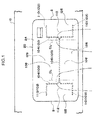
Fig. 1 is a schematic enlarged front view that relates to a glove box door built-in-type knee airbag device relating to a first embodiment, and that illustrates the shapes of tear portions of a glove box door in relation to the knees of a seated vehicle occupant. -
Fig. 2 is a perspective view showing a process (initial stage of expansion) in which the glove box door built-in-type knee airbag device shown inFig. 1 operates and a knee airbag inflates and expands. -
Fig. 3 is a similar perspective view showing a process (initial stage of expansion) in which the glove box door built-in-type knee airbag device shown inFig. 1 operates and the knee airbag inflates and expands. -
Fig. 4 is a similar perspective view showing a process (intermediate stage of expansion) in which the glove box door built-in-type knee airbag device shown inFig. 1 operates and the knee airbag inflates and expands. -
Fig. 5 is a similar perspective view showing a process (completion of expansion) in which the glove box door built-in-type knee airbag device shown inFig. 1 operates and the knee airbag inflates and expands. -
Fig. 6A is a schematic longitudinal sectional view showing the positional relationship between the glove box door in a non-operated state and the seated vehicle occupant, as seen from a side of the vehicle. -
Fig. 6B is a schematic longitudinal sectional view showing the positional relationship between the glove box door in an operated state (initial stage of expansion) and the seated vehicle occupant, as seen from a side of the vehicle. -
Fig. 7 is an exploded perspective view of the glove box door. -
Fig. 8 is an enlarged longitudinal sectional view of main portions (an enlarged sectional view along line 1-1 ofFig. 5 ) of the glove box door built-in-type knee airbag device relating to the first embodiment. -
Fig. 9 is an external front view of an instrument panel in which the glove box door built-in-type knee airbag device relating to the first embodiment is installed. -
Fig. 10A is a schematic plan view that relates to a glove box door built-in-type knee airbag device relating to a second embodiment, and that illustrates a state before operation. -
Fig. 10B is a schematic plan view that relates to the glove box door built-in-type knee airbag device relating to the second embodiment, and that illustrates a state after operation. -
Fig. 11 is a schematic enlarged front view that relates to the glove box door built-in-type knee airbag device relating to the second embodiment, and that illustrates the shapes of tear portions of a glove box door in relation to the knees of a seated vehicle occupant. -
Fig. 12A is an enlarged front view showing a first modified example of tear portion shapes. -
Fig. 12B is an enlarged front view showing a second modified example of tear portion shapes. -
Fig. 13 is a schematic enlarged front view that relates to a glove box door built-in-type knee airbag device relating to a third embodiment, and that illustrates the shapes of tear portions of a glove box door in relation to the knees of a seated vehicle occupant. -
Fig. 14 is a front view that relates to a glove box door built-in-type knee airbag device relating to a fourth embodiment, and that extracts main portions fromFig. 13 . -
Fig. 15 is a line 15-15 enlarged sectional view ofFig. 14 . -
Fig. 16 is a front view, corresponding toFig. 14 , for explaining the structure of first door hinges. -
Fig. 17 is a line 17-17 sectional view ofFig. 16 . -
Fig. 18A is a perspective view of an expanded state of first airbag doors and second airbag doors, relating to an explanatory drawing for explaining the operation and effects of the fourth embodiment. -
Fig. 18B is a plan view of the expanded state of the first airbag doors and the second airbag doors, relating to an explanatory drawing for explaining the operation and effects of the fourth embodiment. -
Fig. 18C is a side view of the expanded state of the first airbag doors and the second airbag doors, relating to an explanatory drawing for explaining the operation and effects of the fourth embodiment. - [First Embodiment]
- Hereinafter, a first embodiment of a knee airbag device for a vehicle relating to the present invention is described by using
Fig. 1 through Fig. 9 . Note that arrow FR shown appropriately in these drawings indicates the vehicle front side, arrow UP indicates the vehicle upper side, and arrow IN indicates the vehicle transverse direction inner side. - An external front view of an instrument panel in which the glove box door built-in-type knee airbag device relating to the present embodiment is installed is shown in
Fig. 9 . Further, an enlarged longitudinal sectional view of main portions (an enlarged sectional view along line 8-8 ofFig. 9 ) of the glove box door built-in-type knee airbag device at a time of non-operation is shown inFig. 8 . Moreover, an exploded perspective view of a glove box door is shown inFig. 7 . Further, schematic longitudinal sectional views showing the positional relationship between the glove box door a seated vehicle occupant, as seen from a side of the vehicle, are shown inFig. 6A, Fig. 6B . First, the structure of the device overall is described by using these drawings. - As shown in
Fig. 9 , aglove box 14 for placing small items is disposed at a position substantially opposing the knees of a vehicle occupant at the front passenger's seat side of an instrument panel 10 (more accurately, at the upper portion of an instrument panel lower 12 that structures the lower portion of the instrument panel 10). As shown inFig. 8 , theglove box 14 is structured by a glove boxmain body 16 that is made of resin and is formed in the shape of a box, and aglove box door 20 that serves as an airbag cover that opens and closes anopening portion 18 of the glove boxmain body 16. The glove boxmain body 16 is disposed such that the openingportion 18 faces the vehicle rear side (the vehicle cabin inner side). - As shown in
Fig. 7 andFig. 8 , a glove box door built-in-typeknee airbag device 40 is built in theglove box door 20 that closes the openingportion 18 of the above-described glove boxmain body 16. Theglove box door 20 has a glove box door outer 24, that is disposed at the vehicle cabin inner side and forms the design surface and is rectangular panel shaped, and a glove box door inner 26, that is disposed at the vehicle front side of this glove box door outer 24 and is fit on the glove box door outer 24 and is rectangular frame shaped. The glove box door outer 24 and the glove box door inner 26 are both made of resin. - The glove box door outer 24 is structured as a two-layer structure of a
base member 28 that is formed in a substantially rectangular panel shape, and asurface skin 30 that covers the vehicle cabin inner side surface of thebase member 28. Both thebase member 28 and thesurface skin 30 are made of resin, but thesurface skin 30 is structured of a resin material that is softer than thebase member 28. A pair of left andright stoppers 32 stand erect at the both sides of the lower edge side of thebase member 28. Each of thestoppers 32 extends from ageneral portion 28A of thebase member 28 toward a surface orthogonal direction (the vehicle front side), and, when theglove box door 20 is in a fully open state, the distal end portions interfere with wall surfaces of the glove boxmain body 16, and thestoppers 32 perform the function of holding theglove box door 20 at the fully open position. - A
hinge 34, that is formed in a substantial L-shape in side view, is provided at the inner side of thestopper 32. One end portion of thehinge 34 is fixed by a screw or the like to the glove boxmain body 16. When theglove box door 20 is opened and closed, theglove box door 20 rotates around rotation center Q inFig. 8 . - On the other hand, the glove box door inner 26 is structured to include a
floor wall portion 26A that is rectangular frame shaped and faces thegeneral portion 28A of thebase member 28 of the glove box door outer 24, a pair of left and rightside wall portions 26B that are formed integrally with the both side portions in the vehicle transverse direction of thefloor wall portion 26A, and a pair of left andright overhang portions 26C that jut-out from the glove box door outer 24 side end portions of the pair of left and rightside wall portions 26B toward the vehicle transverse direction outer sides. Cut-outs 38 are formed in the bottom edge sides of theoverhang portions 26C at positions facing thestoppers 32 of the glove box door outer 24. Thestoppers 32 are inserted within the cut-outs 38. - The glove box door outer 24 and the glove box door inner 26 of the above-described structure are joined together via vertical direction, lateral direction ribs 39 (see
Fig. 8 ) that are formed at at least one of the both. Concretely, the glove box door outer 24 and the glove box door inner 26 are vibration welded at the distal end portions of theribs 39, but fastening by a fastener may be utilized, or vibration welding and fastening may be used in combination, and it suffices for there to be a structure that can make the glove box door outer 24 and the glove box door inner 26 integral. - As shown in
Fig. 7 andFig. 8 , anairbag door retainer 42, that is made of resin and formed in a substantial rectangular flat plate shape, is disposed between the above-described glove box door outer 24 and glove box door inner 26. Theairbag door retainer 42 has abase portion 44 that is rectangular flat plate shaped, and alongitudinal wall portion 46 that is rectangular frame shaped and stands erect from a vicinity of the outer peripheral portion of thebase portion 44. Plural anchor holes 48, that are each structured as a rectangular opening, are formed at predetermined intervals in the upper portion and the lower portion of thelongitudinal wall portion 46. Note that plural ribs 50 for reinforcement, that are disposed so as to span between the both and that are right-triangular in side view, stand erect between a region in the vicinity of the outer peripheral portion of thebase portion 44 and thelongitudinal wall portion 46. - As shown in
Fig. 8 , a pair of upper andlower ribs 60, that extend-out toward theairbag door retainer 42, are formed integrally at the top edge side and the bottom edge side of acentral opening portion 58 that is in thefloor wall portion 26A of the above-described glove box door inner 26. In the assembled state of theglove box door 20, theseribs 60 stand erect in parallel at the outer sides of the top wall portion and the bottom wall portion of thelongitudinal wall portion 46 of theairbag door retainer 42, and the respective distal end portions are welded (vibration welded) to thebase portion 44 of theairbag door retainer 42. Due thereto, thebase portion 44 of theairbag door retainer 42 is fixed in a state of being nipped between thegeneral portion 28A of thebase member 28 of the glove box door outer 24 and theribs 60 of the glove box door inner 26. - Further, as shown in
Fig. 7 andFig. 8 , anairbag module 62 is installed in thecentral opening portion 58 of the glove box door inner 26. Theairbag module 62 has amodule case 64 made of metal. Themodule case 64 forms a box shape whose floor is shallow. Aninflator fixing portion 66, that swells-out from the vehicle front side toward the vehicle rear side by being knocked-out in an isosceles trapezoid shape, is provided at the central lower portion of afloor wall portion 64A of themodule case 64. The longitudinal sectional shape of theinflator fixing portion 66 is mountain shaped. A pair of left and right bolt insert-throughholes 68 are formed in aninclined portion 66A at the vehicle upper side at theinflator fixing portion 66. Due to a pair of stud bolts 72 (seeFig. 8 ), that project-out from the axial direction intermediate portion toward the radial direction outer side of an inflator 70 that serves as a gas generating means, being inserted-in these bolt insert-throughholes 68 andnuts 74 being screwed-together from the reverse surface side, theinflator 70 is fastened and fixed to theinclined portion 66A of theinflator fixing portion 66. - Further, mounting
pieces 78, that are L-shaped and in whose central portions are formed screw insert-throughholes 76, are respectively mounted to a total of four places at the both side portions of themodule case 64. In correspondence therewith, screw insert-throughholes 80 are formed on the same axes as the screw insert-throughholes 76, at the both sides ofcentral opening portion 58 of the glove box door inner 26. Then, by making the bolt insert-throughholes 76 of the respective mountingpieces 78 correspond to the screw insert-throughholes 80 of the glove box door inner 26 side, and by fastening and fixing by unillustrated fasteners such as screws or the like, themodule case 64 is fixed to thecentral opening portion 58 of the glove box door inner 26 from the vehicle front side. - Further,
elongated anchor hardware 82 are mounted to the top portion and the bottom portion of themodule case 64.Anchor pieces 84, that are L-shaped in side view, are formed integrally with one side (theairbag door retainer 42 side) of theanchor hardware 82. Theplural anchor pieces 84 are provided in correspondence with the above-described anchor holes 48 that are formed in thelongitudinal wall portion 46 of theairbag door retainer 42. Then, by inserting therespective anchor pieces 84 into and anchoring them with the respective anchor holes 48, theairbag door retainer 42 is mounted to themodule case 64. - As shown in
Fig. 8 , the inflator 70 that serves as the gas generating means, and aknee airbag 86 that inflates due to gas jetted-out from the inflator 70, are assembled within the above-describedmodule case 64. The inflator 70 is formed in a solid cylindrical shape of an outer diameter that can be contained in themodule case 64. Further, a gas jet-outportion 88 is formed on the same axis, at one end portion in the axial direction of theinflator 70. Moreover, the outer diameter of the gas jet-outportion 88 is shorter than the outer diameter of the inflator 70, and plural gas jet-out holes (not illustrated) are formed in the peripheral wall portion of the gas jet-outportion 88. - On the other hand, the
knee airbag 86 is accommodated within themodule case 64 in a folded-up state. More concretely, theknee airbag 86 is folded-up to a size that can be accommodated in themodule case 64 due to the upper portion and the lower portion of theknee airbag 86 that is in a planar expanded state respectively being folded in the form of bellows and being set toward the central portion. Then, the above-describedinflator 70 is inserted in the central portion (the heightwise direction intermediate portion) of theknee airbag 86, and thestud bolts 72 that project-out from the inflator 70 are passed-through theknee airbag 86, and are fixed to theinflator fixing portion 66 of themodule case 64 in the above-described procedure. Accordingly, theknee airbag 86 is assembled in a state of being nipped between the inflator 70 and theinflator fixing portion 66. Further, in the state in which the glove box door built-in-typeknee airbag device 40 is assembled in the vehicle, theinflator 70 of theknee airbag 86 is a gas flow-in portion 87 (seeFig. 6B ). - Further, the
central opening portion 58 of the glove box door inner 26 is, after assembly of theairbag module 62, closed by a reverse surface cover 92 that is made of resin and formed in a rectangular plate shape.Plural leg portions 94 are formed integrally from the four sides of the reverse surface cover 92 toward the glove box door inner 26 side. A claw is formed at the distal end portion of each of theleg portions 94. In correspondence therewith, plural rectangular insert holes 96 are formed at the outer peripheral portion of thecentral opening portion 58 at thefloor wall portion 26A of the glove box door inner 26. Then, by inserting theleg portions 94 into the insert holes 96 and elastically engaging them, thereverse surface cover 92 is mounted to the surface at the vehicle front side of the glove box door inner 26. - The structure of the airbag doors relating to main portions of the present embodiment is described next.
- As shown in
Fig. 1 , afirst tear portion 100, that is formed in a substantial H shape in front view, andsecond tear portions 102, that are formed so as to be continuous with both sides of thefirst tear portion 100, are formed at the reverse surface (the surface at the vehicle front side) of the glove box door outer 24 at the above-describedglove box door 20. Note that, as can be understood fromFig. 8 , theglove box door 20 of the present embodiment employs, from the standpoint of design, an invisible type tear structure in which thefirst tear portion 100 and thesecond tear portions 102 cannot be visually perceived from the vehicle cabin inner side. Therefore, to be exact, thefirst tear portion 100 and thesecond tear portions 102 cannot be seen when theglove box door 20 is viewed from the front surface, and, when the glove box door outer 24 is viewed from the reverse surface side, thefirst tear portion 100 and thesecond tear portions 102 can be seen. - The
first tear portion 100 is formed in a substantial H shape that includes a pair of left and right verticaldirection tear portions 104, and a first lateraldirection tear portion 106 that connects, in the vehicle transverse direction, vertical direction intermediate portions of these verticaldirection tear portions 104. Note that the connected portions of the verticaldirection tear portions 104 and the first lateraldirection tear portion 106 are sideways Y shapes. Due to thefirst tear portion 100 being set, when bag inflation pressure of greater than or equal to a predetermined value is applied to the glove box door outer 24 via theairbag door retainer 42, a pair of top and bottomfirst airbag doors 108 expand in a double-swing manner in the vehicle vertical direction around first door hinges 126 that are described below. - Further, the
second tear portions 102 are respectively structured by a pair of top and bottom second lateraldirection tear portions 110 that extend in parallel from the both end portions of the respective verticaldirection tear portions 104 toward the sides opposite the first lateraldirection tear portion 106. Due to thesecond tear portions 102 being set, when bag inflation pressure of greater than or equal to a predetermined value is applied to the glove box door outer 24 via theairbag door retainer 42, a pair of left and rightsecond airbag doors 112 expand in a double-swing manner in the vehicle transverse direction around second door hinges 128 that are described below. - As partially shown in
Fig. 7 andFig. 8 ,first groove portions 116 and second groove portions (not illustrated) are formed in the central portion of thebase portion 44 of the airbag door retainer 42 (the portion surrounded by the vertical wall portion 46), so as to correspond to thefirst tear portion 100 and thesecond tear portions 102 formed in the above-described glove box door outer 24, in similar shapes and so as to overlap these. Thefirst groove portions 116 are structured by a first lateraldirection groove portion 120 and a pair of left and right first verticaldirection groove portions 122, and the second groove portions are structured by a total of four second lateraldirection groove portions 124 that respectively extend from the vertical direction both end portions of the respective first verticaldirection groove portions 122 in directions of moving away from one another. - Further, as shown in
Fig. 8 , the first door hinges 126 and the second door hinges 128 (not shown inFig. 8 , seeFig. 1 ) are formed at the inner peripheral side of thevertical wall portion 46 at thebase portion 44 of theairbag door retainer 42. The first door hinges 126 are provided at positions that connect the distal end portions of the pair of left and right verticaldirection tear portions 104 of the glove box door outer 24, and the cross-sectional shape thereof is substantially V-shaped. When thefirst airbag doors 108 expand upward and downward, the first door hinges 126 are expanded while being stretched. Note that the second door hinges 128 also are structured similarly. - Further, as shown in
Fig. 1 , the verticaldirection tear portions 104 are set at vehicle transverse direction outer sides of knee central lines CL of the seated vehicle occupant and at vehicle transverse direction inner sides of vertical direction outer shape lines S of theglove box door 20. - Portions other than the above-described airbag door structure are supplementarily described below. A state in which the glove box door built-in-type
knee airbag device 40 has operated is shown in a side view inFig. 6B . The X line view portion (portion indicated by line X) inFig. 6B is the "upper shin portion" of the vehicle occupant. The upper shin portion X is the region about directly beneath a kneecap (knee joint) Y. - (Operation and Effects of Present Embodiment)
- The operation and effects of the present embodiment are described next.
- When the vehicle, in which the glove box door built-in-type
knee airbag device 40 of the above-described structure is installed, front-collides, the state thereof is sensed by an unillustrated collision sensing means, and a sensing signal is outputted to an airbag ECU. When airbag operation is decided upon by the airbag ECU, various types of airbag devices at the driver's seat side operate, and in addition, the glove box door built-in-typeknee airbag device 40 at the front passenger's seat side also operates. Namely, predetermined current is sent to the squib of theinflator 70 of theairbag module 62 that is built in theglove box door 20, and the inflator 70 is operated. Due thereto, gas is generated from the inflator 70, this gas is supplied into theknee airbag 86 that is housed within theglove box door 20 in a folded-up state, and this is inflated. - When the
knee airbag 86 in the folded-up state inflates and the bag inflation pressure that is applied to thefirst tear portion 100 and thesecond tear portions 102 via theairbag door retainer 42 reaches a predetermined value, thefirst tear portion 100 and thesecond tear portions 102 fracture (rupture), and thefirst airbag doors 108 expand in a double-swing manner in the vehicle vertical direction around the first door hinges 126, and thesecond airbag doors 112 expand in a double-swing manner in the vehicle transverse direction around the second door hinges 128. Due thereto, theknee airbag 86 is inflated and expanded in the gap between the knees of the vehicle occupant and the glove box door 20 (the instrument panel 10). As a result, the knees of the vehicle occupant are restrained and protected by theknee airbag 86. - Here, in the present embodiment, the
knee airbag 86 is disposed at the height of the knees of the vehicle occupant who is in a seated state. Therefore, if the vehicle occupant is seated in the front passenger's seat in a state in which his/her knees are close or the like to theglove box door 20, as shown inFig. 6 , at the time of inflation and expansion of theknee airbag 86, there are cases in which the shin upper portions X are strongly pushed toward the vehicle rear side by the expansion reaction force of theknee airbag 86. To describe in more detail, theglove box 14 is fixed to theinstrument panel 10, and theknee airbag 86 is pushed upward and downward by thefirst airbag doors 108 and the flow of gas in the left and right directions therein also is pushed by the knees Y of the vehicle occupant that are close to thefirst airbag doors 108. Therefore, there is no escape route for the expansion reaction force of theknee airbag 86, and all of the expansion reaction force is transmitted to the upper shin portions X of the vehicle occupant. - However, in the present embodiment, the
second tear portions 102 are formed at the glove box door outer 24 in addition to thefirst tear portion 100, and thesecond airbag doors 112 that expand in the vehicle transverse direction are provided in addition to thefirst airbag doors 108 that expand in the vehicle vertical direction. Therefore, if the knees of the seated vehicle occupant are close or the like to thefirst airbag doors 108, thesecond tear portions 102 fracture (rupture), and thesecond airbag doors 112 are greatly expanded in the vehicle transverse direction before thefirst airbag doors 108. - To describe concretely by using
Fig. 2 through Fig. 5 , first, as shown inFig. 2 , thesecond tear portions 102 fracture (rupture), and thesecond airbag doors 112 start to expand in the vehicle transverse direction. Accompanying this, theknee airbag 86 starts to inflate and expand in the vehicle transverse direction. Further, as shown inFig. 3 , thesecond airbag doors 112 greatly expand in the vehicle transverse direction, and, accompanying this, theknee airbag 86 further proceeds to inflate and expand in the vehicle transverse direction. Next, as shown inFig. 4 , the first lateraldirection tear portion 106 of thefirst tear portion 100 fractures (ruptures), and thefirst airbag door 108 at the upper side is expanded greatly toward the vehicle upper side. Due thereto, the upper portion side of theknee airbag 86 is inflated and expanded. Thereafter, as shown inFig. 5 , thefirst airbag door 108 at the lower side is inflated and expanded toward the vehicle lower side, and theknee airbag 86 is completely inflated and expanded. - In this way, in the present embodiment, in the initial stage of the inflation and expansion process, the both side portions of the
knee airbag 86 are greatly inflated and expanded toward the vehicle transverse direction both sides, and, due thereto, the expansion reaction force of theknee airbag 86 that is applied to the upper shin portions X of the vehicle occupant can be effectively suppressed. As a result, in accordance with the present embodiment, the load on the shins (the upper shin portions X) when theknee airbag 86 inflates and expands in a state in which the knees Y of the vehicle occupant are close or the like to theglove box door 20, can be reduced. - Further, in accordance with the present embodiment, by changing the length of the second lateral
direction tear portions 110, the size of thesecond airbag doors 112 that expand in the vehicle transverse direction can be changed easily. Accordingly, the size of thesecond airbag doors 112 that expand in the vehicle transverse direction can be adjusted simply, and accordingly, the pushing force that pushes the upper shin portions X of the seated vehicle occupant toward the vehicle rear side can be controlled. - Moreover, in the present embodiment, the vertical
direction tear portions 104 are set at the vehicle transverse direction outer sides of the knee central lines CL of the seated vehicle occupant and at the vehicle transverse direction inner sides of the vertical direction outer shape lines S of theglove box door 20. Therefore, providing thesecond tear portions 102 and expanding thesecond airbag doors 112 in the vehicle transverse direction is extremely effective. In other words, from the standpoint of restrictions on the design on theglove box door 20, even if the interval between the knee central line CL of the seated vehicle occupant and the vertical direction outer shape line S of theglove box door 20 is narrow, thesecond airbag doors 112 are expanded, and the load on the upper shin portions X of the vehicle occupant can be reduced. - Further, in the present embodiment, because the
knee airbag 86 is accommodated in theglove box door 20, theknee airbag 86 is inflated and expanded from theglove box door 20. Therefore, there is no need to ensure, within theinstrument panel 10, a space exclusively used for accommodating theknee airbag 86 in the folded-up state. Accordingly, in accordance with the present embodiment, the conventional degrees of freedom in design of theglove box door 20, and accordingly theinstrument panel 10, can be ensured. - [Second Embodiment]
- A second embodiment of a knee airbag device for a vehicle relating to the present invention is described hereinafter by using
Fig. 10 through Fig. 12 . Note that structural portions that are the same as the above-described embodiment are denoted by the same numbers, and description thereof is omitted. - In this second embodiment, the object is to show variations of the tear shapes of the
first tear portion 100 and thesecond tear portions 102 that were described in the above-described first embodiment. - In the embodiment shown in
Fig. 10 , the planar shape of the design surface of theinstrument panel 10 forms a curved shape that extends toward the vehicle rear side from the vehicle transverse direction outer side toward the vehicle transverse direction central side. Note that the embodiment shown in this drawing is a left hand drive vehicle. - In the same way as in the above-described first embodiment, the
glove box door 20 is disposed at the front passenger's seat side of theinstrument panel 10 in which the above-described design is employed, and the glove box door built-in-typeknee airbag device 40 is built within theglove box door 20. - Here, as shown in
Fig. 11 , in this embodiment, the second tear portions are asymmetrical shapes at the left and the right. Concretely, thesecond tear portion 110 at the central side of theinstrument panel 10 is set to be longer than asecond tear portion 130 at the vehicle transverse direction outer side (an unillustrated side door side). - [Operation/Effects]
- In accordance with the above-described structure as well, operation/effects that are similar to those of the above-described first embodiment are obtained.
- In addition, in the present embodiment, the planar shape of the design surface side of the
instrument panel 10 forms a curved shape that extends toward the vehicle rear side from the vehicle transverse direction outer side toward the vehicle transverse direction central side. Therefore, as shown inFig. 10A , at the instrument panel central side, agap 132 between the knee of the vehicle occupant and theinstrument panel 10 is more narrow than agap 134 at the vehicle transverse direction outer side. Therefore, if thesecond tear portions 110, that have symmetrical shapes at the left and the right and at which the tear structure of the present embodiment is not employed, are employed, as shown by the two-dot chain line inFig. 10B , theknee airbag 86 proceeds to inflate and expand toward the vehicle transverse direction outer side (the wide space 134). - However, by forming, in advance, the
second tear portion 110 at the instrument panel central side to be longer in the vehicle transverse direction than thesecond tear portion 130 at the vehicle transverse direction outer side as in the present embodiment, theknee airbag 86 attempts to expand greatly toward the instrument panel central side, and theknee airbag 86, that attempts to inflate and expand toward the vehicle transverse direction outer side, is pulled-back toward the instrument panel central side. As a result, as shown by the solid line inFig. 10B , theknee airbag 86 is inflated and expanded approximately uniformly at the left and right both knees. Accordingly, even if thegap 132 is narrow, thesecond airbag doors 112 are expanded greatly and theknee airbag 86 can be inflated and expanded greatly, and accordingly, the load on the shins of the vehicle occupant can be reduced. - In an embodiment shown in
Fig. 12A , arc-shapedtear portions 136 that are formed in substantially semicircular shapes are formed instead of the verticaldirection tear portions 104 and the second lateraldirection tear portions 110 of the embodiment shown inFig. 10 . Due thereto, a pair of top and bottomfirst airbag doors 138 that are substantially isosceles trapezoid shaped, and a pair of left and rightsecond airbag doors 140 that are substantially semicircular are formed. In addition, in the case of this embodiment, the arc-shapedtear portions 136 perform the functions of both the verticaldirection tear portions 104 and the second lateraldirection tear portions 110. - In an embodiment shown in
Fig. 12B , V-shapedtear portions 142 are used instead of the arc-shapedtear portions 136 of the embodiment shown inFig. 12A . Due thereto, a pair of top and bottomfirst airbag doors 144 that are isosceles trapezoid shaped, and a pair of left and rightsecond airbag doors 146 that are equilateral triangular are formed. In addition, in the case of this embodiment, the V-shapedtear portions 142 perform the functions of both the verticaldirection tear portions 104 and the second lateraldirection tear portions 110. - [Third Embodiment]
- A third embodiment of a knee airbag device for a vehicle relating to the present invention is described hereinafter by using
Fig. 13 . Note that structural portions that are the same as the above-described embodiments are denoted by the same numbers, and description thereof is omitted. - As shown in
Fig. 13 , this third embodiment has the feature in the point that third lateraldirection tear portions 150 are added to thefirst tear portion 100 of the above-described first embodiment. - To describe concretely, the third lateral
direction tear portions 150 are respectively formed, in parallel to the first lateraldirection tear portion 106, at the both end portions in the vertical direction of the verticaldirection tear portions 104. The respective third lateraldirection tear portions 150 are disposed on the same straight lines as the second lateraldirection tear portions 110, and are continuous with the second lateraldirection tear portions 110. - Further, when the distance between the first lateral
direction tear portion 106 and the second lateraldirection tear portion 110 is A, and the length of the second lateraldirection tear portion 110 is B, and the length of the third lateraldirection tear portion 150 is C, they are set to A≈B≈C. - (Operation/Effects)
- In accordance with the above-described structure as well, operation/effects that are similar to those of the above-described first embodiment are obtained.
- In addition, in the present embodiment, the third lateral
direction tear portions 150 that are continuous with the second lateraldirection tear portions 110 are added to the both end portions in the vertical direction of the verticaldirection tear portions 104, and therefore, the following operation/effects are obtained. Namely, if only the second lateraldirection tear portions 110 are formed and the third lateraldirection tear portions 150 are not formed (the case of the above-described first embodiment), due to the first door hinges 126 existing adjacent to the second lateraldirection tear portions 110, the portions that are the intersection points between the verticaldirection tear portions 104 and the second lateraldirection tear portions 110 cannot stretch, and there are cases in which it is difficult to fracture (rupture) the second lateraldirection tear portions 110. - However, in the present embodiment, the third lateral
direction tear portions 150, that extend toward the opposite sides of the second lateraldirection tear portions 110, are added in continuation from the both end portions in the vertical direction of the verticaldirection tear portions 104, and therefore, the portions that are the aforementioned intersection points can stretch. As a result, in accordance with the present embodiment, the second lateraldirection tear portions 110 easily fracture (rupture), and the expandability of thesecond airbag doors 112 that expand in the vehicle transverse direction can be improved. - Further, in the present embodiment, when the distance between the first lateral
direction tear portion 106 and the second lateraldirection tear portion 110 is A, and the length of the second lateraldirection tear portion 110 is B, and the length of the third lateraldirection tear portion 150 is C, they are set to A≈B≈C. Therefore, the first lateraldirection tear portion 106, the verticaldirection tear portions 104, the second lateraldirection tear portions 110, and the third lateraldirection tear portions 150 proceed to fracture (rupture) in a balanced manner. As a result, in accordance with the present embodiment, the expandability of thefirst airbag doors 108, that expand in the vehicle vertical direction, and the expandability of thesecond airbag doors 112, that expand in the vehicle transverse direction, can be further improved. - [Fourth Embodiment]
- A fourth embodiment of a knee airbag device for a vehicle relating to the present invention is described hereinafter by using
Fig. 14 through Fig. 18 . Note that structural portions that are the same as the above-described embodiments are denoted by the same numbers, and description thereof is omitted. - As shown in
Fig. 14 , this fourth embodiment has the feature in the point that the vehicle transverse direction both end portions of thefirst airbag doors 108 in the above-described third embodiment are weakened. - To describe concretely, the
first tear portion 100, thesecond tear portions 102 and the third lateraldirection tear portions 150 that were described in the above-described third embodiment are formed as is at the glove box door outer 24. Then, a total of four regions K1 through K4, that are positioned at the vehicle transverse direction outer sides of the first door hinges 126 at thefirst airbag doors 108, are weakened. Note that doormain body portions 160, that are regions that include the first door hinges 126 at thefirst airbag doors 108, are not weakened. - The method of weakening is described next. As shown in an enlarged manner in
Fig. 15 , in the present embodiment, thin-walled portions 164 are formed at the reverse surface sides of the four regions K1 through K4 of thefirst airbag doors 108 by formingnumerous grooves 162, whose groove longitudinal directions are the vehicle transverse direction, at a predetermined pitch. Thenumerous grooves 162 are structured bydeep grooves 162A andshallow grooves 162B being combined, and bend easily in the arrayed direction of thegrooves 162. Note that the thin-walled portions 164 of the regions K1 through K4 at which thenumerous grooves 162 are formed may be called "weakened portions", "fragile portions" or "low rigidity portions", and, provided that there is a structure that can weaken, all can be applied. For example, the plate thicknesses of all of the regions of K1 through K4 may be set to a predetermined thickness that is thinner than the plate thickness of the doormain body portion 160. - Further, in this fourth embodiment as well, the layout of the vertical
direction tear portions 104, the second lateraldirection tear portions 110, and the third lateraldirection tear portions 150 is set such that the relationship A≈B≈C of the above-described third embodiment is established. Moreover, in this embodiment, a surface area S1 of the doormain body portions 160 of thefirst airbag doors 108 and a surface area S2 of thesecond airbag doors 112 are set so as to be substantially the same. - Moreover, as shown in
Fig. 16 andFig. 17 , the hinge length of bothend portions 126A (i.e., the regions adjacent to the distal end portions of the third lateral direction tear portions 150 (the P line view portions (portions indicated by line P) ofFig. 16 )) of thefirst door hinge 126 are set to be longer than the hinge length ofcentral sides 126B (the Q line view portion (portion indicated by line Q) ofFig. 13 ) of thefirst door hinge 126. - (Operation/Effects)
- In accordance with the above-described structure as well, operation/effects that are similar to those of the above-described third embodiment are obtained.
- In addition, in the present embodiment, because the dimensions of the respective portions are set such that the
surface area S 1 of the doormain body portions 160 of thefirst airbag doors 108 and the surface area S2 of thesecond airbag doors 112 are substantially the same, the bag inflation pressure that thefirst airbag doors 108 and thesecond airbag doors 112 receive is substantially uniform. Therefore, thefirst airbag doors 108 and thesecond airbag doors 112 can be expanded substantially uniformly. As a result, in accordance with the present embodiment, thefirst airbag doors 108 and thesecond airbag doors 112 can be expanded rapidly and smoothly. - Further, as shown in
Fig. 18A through Fig. 18C , by adding the third lateraldirection tear portions 150, at the time of expanding of thefirst airbag doors 108,end portions 108A in the vehicle transverse direction of thefirst airbag doors 108 roll upward. This rolling-up impedes the expansion, in the vehicle vertical direction, of thefirst airbag doors 108. - However, in the present embodiment, all of the regions K1 through K4, that are formed at the outer sides of the first door hinges 126 that are adjacent to the third lateral
direction tear portions 150 and are formed on extended lines thereof at thefirst airbag doors 108, are weakened as compared with the doormain body portions 160 that are the regions other than these. Therefore, even if these regions K1 through K4 at thefirst airbag doors 108 interfere with theinstrument panel 10, they are easily deformed. Accordingly, the expanding operation of thefirst airbag doors 108 is not obstructed. As a result, in accordance with the present embodiment, thefirst airbag doors 108 can be reliably expanded in the vehicle vertical direction. - Moreover, at the regions K1 through K4 that are formed at the outer sides of the first door hinges 126, corner portions D1 at the intersection point sides of the third lateral
direction tear portions 150 and the verticaldirection tear portions 104, and corner portions D2 at the intersection point sides of the first lateraldirection tear portion 106 and the verticaldirection tear portions 104, are both weakened, and therefore, the following operation is obtained. - Namely, when the corner portions D1 at the intersection point sides of the third lateral
direction tear portions 150 and the verticaldirection tear portions 104 are weakened, interference with theinstrument panel 10 is mitigated, and therefore, good expandability of thefirst airbag doors 108 can be ensured. On the other hand, when the corner portions D2 at the intersection point sides of the first lateraldirection tear portion 106 and the verticaldirection tear portions 104, are weakened, interference with theknee airbag 86 is mitigated, and therefore, the load that is transmitted from these corner portions D2 via theknee airbag 86 to the kneeps of the vehicle occupant becomes low. As a result, in accordance with the present embodiment, further improvement in the expandability of thefirst airbag doors 108 can be aimed for, and the load that is transmitted from thefirst airbag doors 108 via theknee airbag 86 to the knees of the vehicle occupant can be suppressed. - Further, in the present embodiment, a hinge length of the third lateral
direction tear portion 150 sides of the first door hinges 126 that are formed adjacent to the third lateraldirection tear portions 150 and on extended lines thereof at thefirst airbag doors 108, is set to be longer than the hinge length at the door hinge central side. Therefore, the third lateraldirection tear portion 150 side, at which the hinge length is relatively long, can smoothly expand by that much. As a result, the expandability of thefirst airbag door 108 can be improved. - [Supplementary Explanation of the Above-Described Embodiments]
- (1) In the above-described embodiments, explanation is given with the glove box door built-in-type
knee airbag device 40 operating at the time of a front collision, but the present invention is not limited to the same, and may operate a glove box door built-in-type knee airbag device in a case in which a collision predicting means such as a pre-crash sensor or the like is installed in a vehicle and collision is predicted by the collision predicting means. - (2) To supplementarily explain the term "built-in" in the case of the glove box door built-in-type
knee airbag device 40 relating to the above-described embodiments, there is no need for all of the main structural elements of the knee airbag device to be disposed at the interior of theglove box door 20, and if at least the knee airbag is disposed at the interior of the glove box door, it is included in "built-in". Accordingly, upon communicating the inflator and the knee airbag by a communicating means such as a hose or the like as described above, the inflator may be provided at the glove boxmain body 16 side, or may be provided at theinstrument panel 10, or may be provided at a body such as an instrument panel reinforcement or the like, or may be provided at an equipment or device such as an air conditioning unit or the like. - (3) In the above-described embodiments, the
airbag module 62 is accommodated within theglove box door 20, but the present invention is not limited to the same, and the airbag module may be accommodated in an airbag case that is provided at the front passenger's seat side of the instrument panel. - (4) In the above-described embodiment, the
first tear portion 100 is formed in a substantial H-shape by the pair of left and right verticaldirection tear portions 104 and the first lateraldirection tear portion 106 that connects these verticaldirection tear portions 104 in the vehicle transverse direction. However, the present invention is not limited to the same, and thefirst tear portion 100 may be formed in a substantial B-shape in which the end portions, that face in the vehicle transverse direction, of the pair of left and right verticaldirection tear portions 104 are connected by lateral direction (fourth) tear portions that extend in the vehicle transverse direction. In this case as well, similar operation and effects are obtained if thefirst airbag doors 108 expand in a double-swing manner in the vehicle vertical direction with the first door hinges 126, that are disposed in parallel above and below, being the centers of the expansion. - (5) Both a case in which the knees of the seated vehicle occupant exist close to the airbag door (e.g., the case shown in
Fig. 6A ), and a case in which the knees of the seated vehicle occupant exist in a state of contacting the airbag door (a case in which the knees push the airbag door), are included in "when an obstruction exists on a locus of movement at an initial stage of expansion of the first airbag doors" of the first aspect of the present invention. - (6) In the above-described fourth embodiment, the entire ranges of the regions K1 through K4 at the
first airbag doors 108 are weakened, but it does not necessarily have to be so, and the corner portions only of the respective regions K1 through K4 may be weakened.
Claims (15)
- A knee airbag device for a vehicle, comprising:gas generating means for generating gas by operating;a knee airbag that is housed in a folded-up state, and that is disposed at a height of knees of a vehicle occupant who is in a seated state, and that inflates and expands toward the knees of the vehicle occupant due to gas supplied from the gas generating means; andan airbag cover that covers the knee airbag in the folded-up state, and that is provided with a first tear portion that, when bag inflation pressure of a predetermined value or greater is applied, fractures, and expands first airbag doors in a vehicle vertical direction, and second tear portions that are formed continuously with the first tear portion and that, even when an obstruction exists on a locus of movement at an initial stage of expansion of the first airbag doors, expand second airbag doors in a vehicle transverse direction.
- The knee airbag device for a vehicle of claim 1, wherein the first tear portion is formed in a substantial H-shape that includes a pair of left and right vertical direction tear portions, and a first lateral direction tear portion that connects these vertical direction tear portions in the vehicle transverse direction, and the second tear portion is structured so as to include second lateral direction tear portions that extend from both end portions of the respective vertical direction tear portions toward sides opposite the first lateral direction tear portion.
- The knee airbag device for a vehicle of claim 2, wherein the first tear portion further includes third lateral direction tear portions that extend from the both end portions of the respective vertical direction tear portions toward sides opposite the second lateral direction tear portions.
- The knee airbag device for a vehicle of claim 3, wherein when a distance between the first lateral direction tear portion and the second lateral direction tear portion is A, and a length of the second lateral direction tear portion is B, and a length of the third lateral direction tear portion is C, they are set to A≈B≈C.
- The knee airbag device for a vehicle of claim 4, wherein a surface area of portions other than regions that are formed at vehicle transverse direction outer sides of door hinges that are formed adjacent to the third lateral direction tear portions and on extended lines thereof at the first airbag doors, and a surface area of the second airbag doors, are set to be substantially the same.
- The knee airbag device for a vehicle of any one of claim 3 through claim 5, wherein at least portions of regions, that are formed at vehicle transverse direction outer sides of door hinges that are formed adjacent to the third lateral direction tear portions and on extended lines thereof at the first airbag doors, are weakened as compared with other regions.
- The knee airbag device for a vehicle of claim 6, wherein weakened portions are provided at at least one of corner portions at intersection point sides of the third lateral direction tear portions and the vertical direction tear portions, and corner portions at intersection point sides of the first lateral direction tear portion and the vertical direction tear portions, at the regions that are formed at the vehicle transverse direction outer sides of the door hinges.
- The knee airbag device for a vehicle of any one of claim 3 through claim 7, wherein a hinge length, at third lateral direction tear portion sides, of door hinges that are formed adjacent to the third lateral direction tear portions and on extended lines thereof at the first airbag doors, is set to be longer than a hinge length at a door hinge central side.
- The knee airbag device for a vehicle of any one of claim 2 through claim 8, wherein the vertical direction tear portions are set at vehicle transverse direction outer sides of knee central lines of a seated vehicle occupant and at vehicle transverse direction inner sides of vertical direction outer shape lines of the airbag cover.
- The knee airbag device for a vehicle of any one of claim 2 through claim 9, wherein connected portions of the vertical direction tear portions and the first lateral direction tear portion are formed in sideways Y-shapes.
- The knee airbag device for a vehicle of any one of claim 2 through claim 9, wherein arc-shaped tear portions are formed instead of the vertical direction tear portions and the second lateral direction tear portions.
- The knee airbag device for a vehicle of any one of claim 2 through claim 9, wherein V-shaped tear portions are formed instead of the vertical direction tear portions and the second lateral direction tear portions.
- The knee airbag device for a vehicle of any one of claim 6 through claim 12, wherein regions are weakened by forming numerous grooves, whose groove longitudinal direction is the vehicle transverse direction, at a predetermined pitch at a reverse surface side of regions formed at outer sides of the door hinges.
- The knee airbag device for a vehicle of any one of claim 1 through claim 13, wherein the knee airbag is housed in a glove box door that is provided at a front passenger's seat side of an instrument panel.
- The knee airbag device for a vehicle of claim 14, wherein
a planar shape of a design surface side of the instrument panel forms a curved shape that extends toward a vehicle rear side from a vehicle transverse direction outer side to a vehicle transverse direction central side,
the second tear portions are set at both a vehicle transverse direction outer side of the first tear portion and an instrument panel central side, and
the second tear portion at the instrument panel central side is set to be longer than the second tear portion at the vehicle transverse direction outer side.
Applications Claiming Priority (2)
| Application Number | Priority Date | Filing Date | Title |
|---|---|---|---|
| JP2008227571A JP4535183B2 (en) | 2008-09-04 | 2008-09-04 | Knee airbag device for vehicle |
| PCT/JP2009/065274 WO2010026970A1 (en) | 2008-09-04 | 2009-09-01 | Knee airbag device for vehicle |
Publications (3)
| Publication Number | Publication Date |
|---|---|
| EP2322390A1 true EP2322390A1 (en) | 2011-05-18 |
| EP2322390A4 EP2322390A4 (en) | 2012-01-25 |
| EP2322390B1 EP2322390B1 (en) | 2013-10-30 |
Family
ID=41797137
Family Applications (1)
| Application Number | Title | Priority Date | Filing Date |
|---|---|---|---|
| EP09811496.0A Active EP2322390B1 (en) | 2008-09-04 | 2009-09-01 | Knee airbag device for vehicle |
Country Status (4)
| Country | Link |
|---|---|
| US (1) | US8408589B2 (en) |
| EP (1) | EP2322390B1 (en) |
| JP (1) | JP4535183B2 (en) |
| WO (1) | WO2010026970A1 (en) |
Cited By (2)
| Publication number | Priority date | Publication date | Assignee | Title |
|---|---|---|---|---|
| EP2674334A1 (en) * | 2012-06-15 | 2013-12-18 | Faurecia Interieur Industrie | Cover of an airbag module having an area forming an hinge with variable lenght |
| CN104057910A (en) * | 2013-03-21 | 2014-09-24 | 现代摩比斯株式会社 | Airbag door |
Families Citing this family (17)
| Publication number | Priority date | Publication date | Assignee | Title |
|---|---|---|---|---|
| US8448980B1 (en) | 2012-05-01 | 2013-05-28 | Ford Global Technologies, Llc | Active bolster with unsymmetric pleated inflation |
| US8596681B1 (en) | 2012-05-30 | 2013-12-03 | Nissan North America, Inc. | Internal deployable vehicle panel assembly |
| US8814201B2 (en) * | 2012-08-17 | 2014-08-26 | Chrysler Group Llc | Knee airbag having increased package width |
| US8955914B2 (en) | 2013-05-31 | 2015-02-17 | B/E Aerospace, Inc. | Leg restraint device for side-seated vehicle occupants |
| US9315271B2 (en) | 2013-05-31 | 2016-04-19 | B/E Aerospace, Inc. | Leg restraint device for side-facing seated vehicle occupants |
| US8894095B1 (en) * | 2013-05-31 | 2014-11-25 | B/E Aerospace, Inc. | Leg restraint device for side-facing seated vehicle occupants |
| WO2015061336A2 (en) * | 2013-10-22 | 2015-04-30 | B/E Aerospace, Inc. | Leg restraint device for side-facing seated vehicle occupants |
| US9156408B1 (en) | 2014-05-28 | 2015-10-13 | Ford Global Technologies, Llc | Active glove box door with reaction surface catcher |
| US9156422B1 (en) * | 2014-08-18 | 2015-10-13 | Ford Global Technologies, Llc | Active bolster with multiple bladders on single trim piece |
| JP6237535B2 (en) * | 2014-08-25 | 2017-11-29 | 豊田合成株式会社 | Lower limb protection airbag |
| JP6303935B2 (en) * | 2014-09-08 | 2018-04-04 | 豊田合成株式会社 | Lower limb protection airbag |
| US9421933B1 (en) * | 2015-04-21 | 2016-08-23 | Ford Global Technologies, Llc | Active glove box door with intermediate skeleton member |
| US9731674B2 (en) | 2015-09-11 | 2017-08-15 | Ford Global Technologies, Llc | Airbag assembly including depressed region below steering column |
| US9789838B1 (en) * | 2016-04-04 | 2017-10-17 | Autoliv Asp, Inc. | Airbag cover weakening patterns and related systems and methods |
| US10759376B2 (en) * | 2018-08-06 | 2020-09-01 | Ford Global Technologies, Llc | Vehicle airbag |
| US11052855B2 (en) * | 2019-06-20 | 2021-07-06 | Ford Global Technologies, Llc | Selective deployment of deflectors for an airbag |
| US11351945B1 (en) * | 2021-01-20 | 2022-06-07 | Faurecia Interior Systems, Inc. | Knee airbag cover |
Family Cites Families (28)
| Publication number | Priority date | Publication date | Assignee | Title |
|---|---|---|---|---|
| US5013064A (en) * | 1990-05-29 | 1991-05-07 | General Motors Corporation | Occupant restraint system |
| DE19718931C1 (en) * | 1997-04-28 | 1998-08-06 | Petri Ag | Air-bag cover with supporting and top layers |
| DE29807424U1 (en) | 1998-04-23 | 1998-08-27 | Trw Repa Gmbh | Knee protection device for vehicle occupants |
| JP2000264159A (en) * | 1999-03-19 | 2000-09-26 | Nippon Plast Co Ltd | Manufacture of air bag cover |
| JP2001106010A (en) * | 1999-10-06 | 2001-04-17 | Toyota Central Res & Dev Lab Inc | Airbag module cover |
| JP2001180417A (en) | 1999-12-21 | 2001-07-03 | Daihatsu Motor Co Ltd | Cover structure for air bag device |
| JP2002029355A (en) * | 2000-07-13 | 2002-01-29 | Toyota Motor Corp | Airbag device |
| JP2002356137A (en) | 2001-05-30 | 2002-12-10 | Takata Corp | Vehicular occupant crash protection device |
| CN1582237A (en) * | 2001-10-23 | 2005-02-16 | 通用电气公司 | Dashboard system with hidden airbag doors |
| US7175195B2 (en) * | 2002-12-25 | 2007-02-13 | Toyoda Gosei Co., Ltd. | Occupant protection device |
| JP2005067466A (en) | 2003-08-26 | 2005-03-17 | Takata Corp | Occupant-leg protection device |
| JP4478826B2 (en) * | 2003-11-21 | 2010-06-09 | 株式会社イノアックコーポレーション | Skin material and molding method thereof |
| US7261318B2 (en) | 2003-12-01 | 2007-08-28 | Autoliv Asp, Inc. | Knee airbag and glove box assembly |
| JP4368186B2 (en) * | 2003-12-03 | 2009-11-18 | 芦森工業株式会社 | Air grid |
| JP4446830B2 (en) | 2004-07-29 | 2010-04-07 | 日本プラスト株式会社 | Airbag device |
| US7328913B2 (en) | 2004-11-15 | 2008-02-12 | Cis Tech, Llc | Low risk deployment passenger airbag system |
| JP4717532B2 (en) * | 2005-07-05 | 2011-07-06 | 三光合成株式会社 | Airbag device for automobile |
| JP2007055413A (en) * | 2005-08-24 | 2007-03-08 | Daikyoo Nishikawa Kk | Interior parts for vehicles with airbag doors |
| JP2007153222A (en) | 2005-12-07 | 2007-06-21 | Nippon Plast Co Ltd | Airbag device for automobile |
| JP4605000B2 (en) * | 2005-12-14 | 2011-01-05 | トヨタ自動車株式会社 | Air bag device for knee protection |
| JP4432932B2 (en) | 2006-05-09 | 2010-03-17 | トヨタ自動車株式会社 | Vehicle knee airbag device and vehicle knee airbag deployment method |
| JP2008073794A (en) * | 2006-09-20 | 2008-04-03 | Toyota Motor Corp | Tier line forming method and apparatus therefor |
| DE602007013086D1 (en) | 2006-09-29 | 2011-04-21 | Toyota Motor Co Ltd | Knee protection airbag device |
| JP4231519B2 (en) * | 2006-11-24 | 2009-03-04 | トヨタ自動車株式会社 | Knee airbag device with column |
| JP2008174210A (en) * | 2006-12-19 | 2008-07-31 | Mazda Motor Corp | Vehicle leg protection airbag device |
| KR100886125B1 (en) * | 2007-11-01 | 2009-02-27 | 현대모비스 주식회사 | Car Instrument Panel |
| JP5321581B2 (en) * | 2008-10-29 | 2013-10-23 | トヨタ自動車株式会社 | Knee airbag device for vehicle |
| JP2010173505A (en) * | 2009-01-30 | 2010-08-12 | Toyoda Gosei Co Ltd | Front passenger seat airbag device |
-
2008
- 2008-09-04 JP JP2008227571A patent/JP4535183B2/en active Active
-
2009
- 2009-09-01 US US13/061,546 patent/US8408589B2/en active Active
- 2009-09-01 WO PCT/JP2009/065274 patent/WO2010026970A1/en not_active Ceased
- 2009-09-01 EP EP09811496.0A patent/EP2322390B1/en active Active
Cited By (4)
| Publication number | Priority date | Publication date | Assignee | Title |
|---|---|---|---|---|
| EP2674334A1 (en) * | 2012-06-15 | 2013-12-18 | Faurecia Interieur Industrie | Cover of an airbag module having an area forming an hinge with variable lenght |
| FR2991941A1 (en) * | 2012-06-15 | 2013-12-20 | Faurecia Interieur Ind | DEVICE FOR CLOSING AN INFLATABLE CUSHION MODULE COMPRISING A VARIABLE LENGTH HINGE AREA |
| US9193323B2 (en) | 2012-06-15 | 2015-11-24 | Faurecia Interieur Industrie | Airbag cover door having a variable length hinge |
| CN104057910A (en) * | 2013-03-21 | 2014-09-24 | 现代摩比斯株式会社 | Airbag door |
Also Published As
| Publication number | Publication date |
|---|---|
| US8408589B2 (en) | 2013-04-02 |
| EP2322390B1 (en) | 2013-10-30 |
| JP4535183B2 (en) | 2010-09-01 |
| WO2010026970A1 (en) | 2010-03-11 |
| US20110272929A1 (en) | 2011-11-10 |
| JP2010058708A (en) | 2010-03-18 |
| EP2322390A4 (en) | 2012-01-25 |
Similar Documents
| Publication | Publication Date | Title |
|---|---|---|
| US8408589B2 (en) | Knee airbag device for vehicle | |
| US8308189B2 (en) | Knee airbag for vehicle | |
| JP4591574B2 (en) | Knee airbag device for vehicle | |
| EP2353947B1 (en) | Knee airbag device for vehicle | |
| CN108177629B (en) | Vehicle side structure | |
| US10800369B2 (en) | Rear seat side airbag device | |
| EP3437938B1 (en) | Rider protection device | |
| US9004529B2 (en) | Vehicle side door structure and passenger protecting system | |
| JP2009149135A (en) | Deployment restriction member for curtain airbag, and arrangement part structure for curtain airbag | |
| JP2002356136A (en) | Vehicular occupant crash protection device | |
| US7695001B2 (en) | Vehicle protection apparatus with cover having a rupturable portion with tear tabs | |
| US11904970B2 (en) | Airbag module | |
| EP2460695A1 (en) | Column-mounted knee airbag device | |
| US8215666B2 (en) | Knee air bag device for vehicle | |
| JP6754347B2 (en) | Airbag device | |
| JP5315010B2 (en) | Knee airbag device for vehicle | |
| JP2014213749A (en) | Air bag | |
| JP2009132212A (en) | Knee airbag device for vehicle | |
| JP3418867B2 (en) | Cleavage structure of airbag door | |
| WO2008054266A1 (en) | An air-bag arrangement | |
| JP2008149930A (en) | Vehicle leg protection airbag device | |
| JP2010064565A (en) | Vehicular airbag device | |
| JP2010058553A (en) | Vehicular knee airbag device | |
| JP2005280450A (en) | Air bag device | |
| JP2017197094A (en) | Curtain airbag holding member and curtain airbag device |
Legal Events
| Date | Code | Title | Description |
|---|---|---|---|
| PUAI | Public reference made under article 153(3) epc to a published international application that has entered the european phase |
Free format text: ORIGINAL CODE: 0009012 |
|
| 17P | Request for examination filed |
Effective date: 20110302 |
|
| AK | Designated contracting states |
Kind code of ref document: A1 Designated state(s): AT BE BG CH CY CZ DE DK EE ES FI FR GB GR HR HU IE IS IT LI LT LU LV MC MK MT NL NO PL PT RO SE SI SK SM TR |
|
| AX | Request for extension of the european patent |
Extension state: AL BA RS |
|
| DAX | Request for extension of the european patent (deleted) | ||
| A4 | Supplementary search report drawn up and despatched |
Effective date: 20111223 |
|
| RIC1 | Information provided on ipc code assigned before grant |
Ipc: B60R 21/20 20110101AFI20111219BHEP |
|
| 17Q | First examination report despatched |
Effective date: 20121204 |
|
| RAP1 | Party data changed (applicant data changed or rights of an application transferred) |
Owner name: TOYOTA JIDOSHA KABUSHIKI KAISHA |
|
| GRAP | Despatch of communication of intention to grant a patent |
Free format text: ORIGINAL CODE: EPIDOSNIGR1 |
|
| INTG | Intention to grant announced |
Effective date: 20130515 |
|
| GRAS | Grant fee paid |
Free format text: ORIGINAL CODE: EPIDOSNIGR3 |
|
| GRAA | (expected) grant |
Free format text: ORIGINAL CODE: 0009210 |
|
| AK | Designated contracting states |
Kind code of ref document: B1 Designated state(s): AT BE BG CH CY CZ DE DK EE ES FI FR GB GR HR HU IE IS IT LI LT LU LV MC MK MT NL NO PL PT RO SE SI SK SM TR |
|
| REG | Reference to a national code |
Ref country code: GB Ref legal event code: FG4D |
|
| REG | Reference to a national code |
Ref country code: CH Ref legal event code: EP |
|
| REG | Reference to a national code |
Ref country code: AT Ref legal event code: REF Ref document number: 638376 Country of ref document: AT Kind code of ref document: T Effective date: 20131115 |
|
| REG | Reference to a national code |
Ref country code: IE Ref legal event code: FG4D |
|
| REG | Reference to a national code |
Ref country code: DE Ref legal event code: R096 Ref document number: 602009019803 Country of ref document: DE Effective date: 20131224 |
|
| REG | Reference to a national code |
Ref country code: NL Ref legal event code: VDEP Effective date: 20131030 |
|
| REG | Reference to a national code |
Ref country code: AT Ref legal event code: MK05 Ref document number: 638376 Country of ref document: AT Kind code of ref document: T Effective date: 20131030 |
|
| REG | Reference to a national code |
Ref country code: LT Ref legal event code: MG4D |
|
| REG | Reference to a national code |
Ref country code: DE Ref legal event code: R084 Ref document number: 602009019803 Country of ref document: DE Effective date: 20140304 |
|
| PG25 | Lapsed in a contracting state [announced via postgrant information from national office to epo] |
Ref country code: LT Free format text: LAPSE BECAUSE OF FAILURE TO SUBMIT A TRANSLATION OF THE DESCRIPTION OR TO PAY THE FEE WITHIN THE PRESCRIBED TIME-LIMIT Effective date: 20131030 Ref country code: HR Free format text: LAPSE BECAUSE OF FAILURE TO SUBMIT A TRANSLATION OF THE DESCRIPTION OR TO PAY THE FEE WITHIN THE PRESCRIBED TIME-LIMIT Effective date: 20131030 Ref country code: SE Free format text: LAPSE BECAUSE OF FAILURE TO SUBMIT A TRANSLATION OF THE DESCRIPTION OR TO PAY THE FEE WITHIN THE PRESCRIBED TIME-LIMIT Effective date: 20131030 Ref country code: IS Free format text: LAPSE BECAUSE OF FAILURE TO SUBMIT A TRANSLATION OF THE DESCRIPTION OR TO PAY THE FEE WITHIN THE PRESCRIBED TIME-LIMIT Effective date: 20140228 Ref country code: BE Free format text: LAPSE BECAUSE OF FAILURE TO SUBMIT A TRANSLATION OF THE DESCRIPTION OR TO PAY THE FEE WITHIN THE PRESCRIBED TIME-LIMIT Effective date: 20131030 Ref country code: NL Free format text: LAPSE BECAUSE OF FAILURE TO SUBMIT A TRANSLATION OF THE DESCRIPTION OR TO PAY THE FEE WITHIN THE PRESCRIBED TIME-LIMIT Effective date: 20131030 Ref country code: FI Free format text: LAPSE BECAUSE OF FAILURE TO SUBMIT A TRANSLATION OF THE DESCRIPTION OR TO PAY THE FEE WITHIN THE PRESCRIBED TIME-LIMIT Effective date: 20131030 Ref country code: NO Free format text: LAPSE BECAUSE OF FAILURE TO SUBMIT A TRANSLATION OF THE DESCRIPTION OR TO PAY THE FEE WITHIN THE PRESCRIBED TIME-LIMIT Effective date: 20140130 |
|
| PG25 | Lapsed in a contracting state [announced via postgrant information from national office to epo] |
Ref country code: LV Free format text: LAPSE BECAUSE OF FAILURE TO SUBMIT A TRANSLATION OF THE DESCRIPTION OR TO PAY THE FEE WITHIN THE PRESCRIBED TIME-LIMIT Effective date: 20131030 Ref country code: AT Free format text: LAPSE BECAUSE OF FAILURE TO SUBMIT A TRANSLATION OF THE DESCRIPTION OR TO PAY THE FEE WITHIN THE PRESCRIBED TIME-LIMIT Effective date: 20131030 Ref country code: ES Free format text: LAPSE BECAUSE OF FAILURE TO SUBMIT A TRANSLATION OF THE DESCRIPTION OR TO PAY THE FEE WITHIN THE PRESCRIBED TIME-LIMIT Effective date: 20131030 Ref country code: CY Free format text: LAPSE BECAUSE OF FAILURE TO SUBMIT A TRANSLATION OF THE DESCRIPTION OR TO PAY THE FEE WITHIN THE PRESCRIBED TIME-LIMIT Effective date: 20131030 |
|
| PG25 | Lapsed in a contracting state [announced via postgrant information from national office to epo] |
Ref country code: PT Free format text: LAPSE BECAUSE OF FAILURE TO SUBMIT A TRANSLATION OF THE DESCRIPTION OR TO PAY THE FEE WITHIN THE PRESCRIBED TIME-LIMIT Effective date: 20140228 |
|
| PG25 | Lapsed in a contracting state [announced via postgrant information from national office to epo] |
Ref country code: EE Free format text: LAPSE BECAUSE OF FAILURE TO SUBMIT A TRANSLATION OF THE DESCRIPTION OR TO PAY THE FEE WITHIN THE PRESCRIBED TIME-LIMIT Effective date: 20131030 |
|
| REG | Reference to a national code |
Ref country code: DE Ref legal event code: R097 Ref document number: 602009019803 Country of ref document: DE |
|
| PG25 | Lapsed in a contracting state [announced via postgrant information from national office to epo] |
Ref country code: SK Free format text: LAPSE BECAUSE OF FAILURE TO SUBMIT A TRANSLATION OF THE DESCRIPTION OR TO PAY THE FEE WITHIN THE PRESCRIBED TIME-LIMIT Effective date: 20131030 Ref country code: RO Free format text: LAPSE BECAUSE OF FAILURE TO SUBMIT A TRANSLATION OF THE DESCRIPTION OR TO PAY THE FEE WITHIN THE PRESCRIBED TIME-LIMIT Effective date: 20131030 Ref country code: PL Free format text: LAPSE BECAUSE OF FAILURE TO SUBMIT A TRANSLATION OF THE DESCRIPTION OR TO PAY THE FEE WITHIN THE PRESCRIBED TIME-LIMIT Effective date: 20131030 Ref country code: CZ Free format text: LAPSE BECAUSE OF FAILURE TO SUBMIT A TRANSLATION OF THE DESCRIPTION OR TO PAY THE FEE WITHIN THE PRESCRIBED TIME-LIMIT Effective date: 20131030 |
|
| PLBE | No opposition filed within time limit |
Free format text: ORIGINAL CODE: 0009261 |
|
| STAA | Information on the status of an ep patent application or granted ep patent |
Free format text: STATUS: NO OPPOSITION FILED WITHIN TIME LIMIT |
|
| PG25 | Lapsed in a contracting state [announced via postgrant information from national office to epo] |
Ref country code: DK Free format text: LAPSE BECAUSE OF FAILURE TO SUBMIT A TRANSLATION OF THE DESCRIPTION OR TO PAY THE FEE WITHIN THE PRESCRIBED TIME-LIMIT Effective date: 20131030 |
|
| 26N | No opposition filed |
Effective date: 20140731 |
|
| REG | Reference to a national code |
Ref country code: DE Ref legal event code: R097 Ref document number: 602009019803 Country of ref document: DE Effective date: 20140731 |
|
| PG25 | Lapsed in a contracting state [announced via postgrant information from national office to epo] |
Ref country code: SI Free format text: LAPSE BECAUSE OF FAILURE TO SUBMIT A TRANSLATION OF THE DESCRIPTION OR TO PAY THE FEE WITHIN THE PRESCRIBED TIME-LIMIT Effective date: 20131030 |
|
| PG25 | Lapsed in a contracting state [announced via postgrant information from national office to epo] |
Ref country code: MC Free format text: LAPSE BECAUSE OF FAILURE TO SUBMIT A TRANSLATION OF THE DESCRIPTION OR TO PAY THE FEE WITHIN THE PRESCRIBED TIME-LIMIT Effective date: 20131030 Ref country code: LU Free format text: LAPSE BECAUSE OF FAILURE TO SUBMIT A TRANSLATION OF THE DESCRIPTION OR TO PAY THE FEE WITHIN THE PRESCRIBED TIME-LIMIT Effective date: 20140901 |
|
| REG | Reference to a national code |
Ref country code: CH Ref legal event code: PL |
|
| GBPC | Gb: european patent ceased through non-payment of renewal fee |
Effective date: 20140901 |
|
| REG | Reference to a national code |
Ref country code: IE Ref legal event code: MM4A |
|
| PG25 | Lapsed in a contracting state [announced via postgrant information from national office to epo] |
Ref country code: GB Free format text: LAPSE BECAUSE OF NON-PAYMENT OF DUE FEES Effective date: 20140901 Ref country code: CH Free format text: LAPSE BECAUSE OF NON-PAYMENT OF DUE FEES Effective date: 20140930 Ref country code: LI Free format text: LAPSE BECAUSE OF NON-PAYMENT OF DUE FEES Effective date: 20140930 |
|
| PG25 | Lapsed in a contracting state [announced via postgrant information from national office to epo] |
Ref country code: IE Free format text: LAPSE BECAUSE OF NON-PAYMENT OF DUE FEES Effective date: 20140901 |
|
| PG25 | Lapsed in a contracting state [announced via postgrant information from national office to epo] |
Ref country code: SM Free format text: LAPSE BECAUSE OF FAILURE TO SUBMIT A TRANSLATION OF THE DESCRIPTION OR TO PAY THE FEE WITHIN THE PRESCRIBED TIME-LIMIT Effective date: 20131030 |
|
| PG25 | Lapsed in a contracting state [announced via postgrant information from national office to epo] |
Ref country code: GR Free format text: LAPSE BECAUSE OF FAILURE TO SUBMIT A TRANSLATION OF THE DESCRIPTION OR TO PAY THE FEE WITHIN THE PRESCRIBED TIME-LIMIT Effective date: 20140131 Ref country code: BG Free format text: LAPSE BECAUSE OF FAILURE TO SUBMIT A TRANSLATION OF THE DESCRIPTION OR TO PAY THE FEE WITHIN THE PRESCRIBED TIME-LIMIT Effective date: 20131030 Ref country code: MT Free format text: LAPSE BECAUSE OF FAILURE TO SUBMIT A TRANSLATION OF THE DESCRIPTION OR TO PAY THE FEE WITHIN THE PRESCRIBED TIME-LIMIT Effective date: 20131030 |
|
| PG25 | Lapsed in a contracting state [announced via postgrant information from national office to epo] |
Ref country code: TR Free format text: LAPSE BECAUSE OF FAILURE TO SUBMIT A TRANSLATION OF THE DESCRIPTION OR TO PAY THE FEE WITHIN THE PRESCRIBED TIME-LIMIT Effective date: 20131030 Ref country code: HU Free format text: LAPSE BECAUSE OF FAILURE TO SUBMIT A TRANSLATION OF THE DESCRIPTION OR TO PAY THE FEE WITHIN THE PRESCRIBED TIME-LIMIT; INVALID AB INITIO Effective date: 20090901 |
|
| REG | Reference to a national code |
Ref country code: FR Ref legal event code: PLFP Year of fee payment: 8 |
|
| REG | Reference to a national code |
Ref country code: FR Ref legal event code: PLFP Year of fee payment: 9 |
|
| PG25 | Lapsed in a contracting state [announced via postgrant information from national office to epo] |
Ref country code: MK Free format text: LAPSE BECAUSE OF FAILURE TO SUBMIT A TRANSLATION OF THE DESCRIPTION OR TO PAY THE FEE WITHIN THE PRESCRIBED TIME-LIMIT Effective date: 20131030 |
|
| REG | Reference to a national code |
Ref country code: FR Ref legal event code: PLFP Year of fee payment: 10 |
|
| P01 | Opt-out of the competence of the unified patent court (upc) registered |
Effective date: 20230427 |
|
| PGFP | Annual fee paid to national office [announced via postgrant information from national office to epo] |
Ref country code: DE Payment date: 20250730 Year of fee payment: 17 |
|
| PGFP | Annual fee paid to national office [announced via postgrant information from national office to epo] |
Ref country code: IT Payment date: 20250825 Year of fee payment: 17 |
|
| PGFP | Annual fee paid to national office [announced via postgrant information from national office to epo] |
Ref country code: FR Payment date: 20250808 Year of fee payment: 17 |