EP2322357A1 - Jante de bicyclette en resine renforcée de fibres de carbone dotée d'une partie de frein en céramique - Google Patents
Jante de bicyclette en resine renforcée de fibres de carbone dotée d'une partie de frein en céramique Download PDFInfo
- Publication number
- EP2322357A1 EP2322357A1 EP10176100A EP10176100A EP2322357A1 EP 2322357 A1 EP2322357 A1 EP 2322357A1 EP 10176100 A EP10176100 A EP 10176100A EP 10176100 A EP10176100 A EP 10176100A EP 2322357 A1 EP2322357 A1 EP 2322357A1
- Authority
- EP
- European Patent Office
- Prior art keywords
- bicycle rim
- brake portion
- ceramic
- carbon
- carbon bodied
- Prior art date
- Legal status (The legal status is an assumption and is not a legal conclusion. Google has not performed a legal analysis and makes no representation as to the accuracy of the status listed.)
- Withdrawn
Links
Images


Classifications
-
- B—PERFORMING OPERATIONS; TRANSPORTING
- B60—VEHICLES IN GENERAL
- B60B—VEHICLE WHEELS; CASTORS; AXLES FOR WHEELS OR CASTORS; INCREASING WHEEL ADHESION
- B60B5/00—Wheels, spokes, disc bodies, rims, hubs, wholly or predominantly made of non-metallic material
- B60B5/02—Wheels, spokes, disc bodies, rims, hubs, wholly or predominantly made of non-metallic material made of synthetic material
-
- B—PERFORMING OPERATIONS; TRANSPORTING
- B60—VEHICLES IN GENERAL
- B60B—VEHICLE WHEELS; CASTORS; AXLES FOR WHEELS OR CASTORS; INCREASING WHEEL ADHESION
- B60B21/00—Rims
- B60B21/08—Rims characterised by having braking surfaces
Definitions
- the present invention relates generally to a carbon bodied bicycle rim and, more particularly, to a carbon bodied bicycle rim having an aluminum layer sprayed thereon and a ceramic layer sprayed on the aluminum layer for heat insulation effect.
- Bicycle rim is an edge of a wheel onto which a tire is fixed.
- Most bicycle rims have been made from metal material such like steel or aluminum.
- the metal material bicycle rims has a stiffness so that the wheel of the bicycle can be provided with durable ability. Even so, the metal material bicycle rims has a disadvantage of heavy weight.
- many bicycle rim manufacturers begun to make their rims with other material.
- US Patent 6761847 discloses a bicycle wheel rim having an inner peripheral wall, an outer peripheral wall, two lateral walls joining said peripheral walls, and two circumferential wings, for anchoring a tire, is provided.
- the method providing a rim made of a single part made of structural fiber based material, preferably carbon fiber material.
- the density of carbon fiber is considerably lower than the density of metal, making it ideal for applications requiring low weight.
- a brake pad will abut against the bicycle rim to slow down the bicycle.
- a heat will be generated between the bicycle rim and the brake pad. The heat will affect the rigidity of the carbon fiber bicycle rim. Even worse, the heat will cause damage to plastic resin which is used to combine the carbon fiber, and peel off the carbon fiber.
- the present invention is, therefore, intended to obviate or at least alleviate the problems encountered in the prior art.
- the main purpose is to provide a carbon bodied bicycle rim with ceramic brake portion which comprises a carbon bodied bicycle rim and a protective film thermal sprayed on the carbon bodied bicycle rim.
- the carbon bodied bicycle rim includes two brake portion respectively formed on two sides thereof. Each brake portion has an outer surface.
- the protective film is thermal sprayed on the outer surface of the brake portion, by which the brake portion has a characteristic of wear-resisting and thermal dissipation.
- the protective film includes an aluminum layer coated on the brake portion and a ceramic layer coated on the aluminum layer.
- the aluminum layer has a first side and a second side opposite to the first side.
- the first side connects onto the outer surface of the brake portion via thermal spraying to provide an excellent bond strength therebetween so that the aluminum layer is firmly coated on the outer surface of the brake portion.
- the ceramic layer includes a connecting side, wherein the connecting side connects onto the second side of the aluminum layer via thermal spraying to provide an excellent bond strength therebetween so that the ceramic layer is firmly coated on the second side of the aluminum layer.
- An advantage of the carbon bodied bicycle rim with ceramic brake portion according to the present invention is that the protective film is thermal sprayed on the outer surface of the brake portion, by which the brake portion has a characteristic of wear-resisting and thermal dissipation.
- Another advantage of the carbon bodied bicycle rim with ceramic brake portion according to the present invention is that the protective film and the brake portion have an excellent bond strength therebetween so that the protective film is firmly coated on the brake portion.
- Another advantage of the carbon bodied bicycle rim with ceramic brake portion according to the present invention is that the aluminum layer has a characteristic of thermal dissipation so that a heat generated from braking process can be quickly dissipated and prevent the carbon bodied bicycle rim from high temperature damage.
- a further advantage of the carbon bodied bicycle rim with ceramic brake portion according to the present invention is that the ceramic layer has a characteristic of high temperature-resistant and wear-resisting so that the ceramic layer can withstand high temperature generated from braking process and be prevented from abrasion.
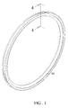
- the carbon bodied bicycle rim 10 which is clincher type, comprises two brake portions 11 respectively formed on two sides thereof, and a connecting portion 12 extended between the brake portions 11. Each brake portion 11 has an outer surface 111.
- the carbon bodied bicycle rim 10 further comprises two flanges 13 formed between the brake portions 11 and the connecting portion 12, respectively.
- the connecting portion 12 and the flanges 13 are adapted for tire installation.
- a method for producing a carbon bodied bicycle rim with ceramic brake portion includes the steps of: (a) preparing a carbon bodied bicycle rim, aluminum material and ceramic material; (b) spraying the aluminum material onto the brake portion of the carbon bodied bicycle rim via thermal spraying process in which the aluminum material is heated to a molten state and accelerated towards the brake portion in the form of micrometer-size particles to form an aluminum layer; and (c) spraying the ceramic material onto the aluminum layer coated on the brake portion via thermal spraying process in which the ceramic material is heated to a molten state and accelerated towards the aluminum layer in the form of micrometer-size particles to form a ceramic layer.
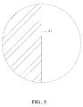
- the aluminum material which is in powder wire or liquid form, is thermal sprayed onto the outer surface 111 of the brake portion 11 of the carbon bodied bicycle rim 10 for protecting the carbon bodied bicycle rim 10 against heat damage generated from braking process.
- the aluminum material which is heated to the molten state, is thermal sprayed onto the outer surface 111 of the brake portion 11 of the carbon bodied bicycle rim 10 to form an aluminum layer 20.
- the aluminum material is thermal sprayed with repeatedly interrupted so as to prevent the brake portion 11 of the carbon bodied bicycle rim 10 from being sprayed too much aluminum material at a time, by which the brake portion 11 is prevented from high temperature damage.
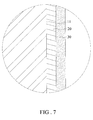
- the aluminum layer 20 includes a first side 21 and a second side 22 opposite to the first side 21.
- the first side 21 connects onto the outer surface 111 of the brake portion 11 via thermal spraying to provide an excellent bond strength therebetween so that the aluminum layer 20 is firmly coated on the outer surface 111 of the brake portion 11 of the carbon bodied bicycle rim 10.
- the aluminum layer 20 has a characteristic of thermal dissipation so that a heat generated from braking process can be quickly dissipated and prevent the carbon bodied bicycle rim 10 from high temperature damage.
- the ceramic material is in powder or rod form.
- the ceramic material which is heated to the molten state, is thermal sprayed onto the aluminum layer 20 coated on the outer surface 111 of the brake portion 11 of the carbon bodied bicycle rim 10 to form an ceramic layer 30.
- the ceramic material is thermal sprayed with repeatedly interrupted so as to prevent the brake portion 11 of the carbon bodied bicycle rim 10 from being sprayed too much ceramic material at a time, by which the brake portion 11 is prevented from high temperature damage.
- the ceramic layer 30 includes a connecting side 31 and a friction side 32.
- the connecting side 31 connects onto the second side 22 of the aluminum layer 20 via thermal spraying to provide an excellent bond strength therebetween so that the ceramic layer 30 is firmly coated on the second side 22 of the aluminum layer 20.
- the ceramic layer 30 has a characteristic of high temperature-resistant and wear-resisting so that the ceramic layer 30 can withstand high temperature generated from braking process and be prevented from abrasion.
- the ceramic layer 30 further has a thermal isolated ability so that the heat generated from braking process will not transmit into the aluminum layer 20 at a time. Hence, the ceramic layer 30 can prevent the carbon bodied bicycle rim 10 from high temperature damage.
- FIG. 8 a cross section view of a carbon bodied bicycle rim with ceramic brake portion 1 according to the first embodiment is shown.
- the aluminum layer 20 is thermal sprayed onto the brake portion 11 of the carbon bodied bicycle rim 10.
- the ceramic layer 30 is thermal sprayed onto the aluminum layer 20.
- the aluminum layer 20 and ceramic layer 30 are defined as a protective film A, by which the brake portion 11 has a characteristic of wear-resisting and thermal dissipation.
- the protective film A and the brake portion 11 have an excellent bond strength therebetween so that the protective film A is firmly coated on the brake portion 11.
- the friction side 32 of the ceramic layer 30 is adapted to be abutted by a brake pad B. While the brake pad B abutted the friction side 32 of the ceramic layer 30 to slow down a bicycle, a heat H is generated by the friction therebetween. Among which, most of the heat H is prevented from transferring into the aluminum layer 20 due to the thermal isolated ability of the ceramic layer 30. Other heat H, which is pass through the ceramic layer 30, is immediately dissipated by the aluminum layer 20 to protect the carbon bodied bicycle rim 10 against heat damage generated from braking process.
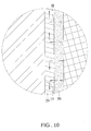
- a carbon bodied bicycle rim with ceramic brake portion 1 according to a second embodiment of the present invention.
- the second embodiment is like the first embodiment except that the carbon bodied bicycle rim 10 is tubular type.
- the carbon bodied bicycle rim 10 comprises two brake portions 11 respectively formed on two sides thereof, and a connecting portion 12 extended between the brake portions 11.
- the brake portions 11 are connected to both sides of the connecting portion 12, respectively.
- the carbon bodied bicycle rim 10 further comprises two flanges 13 formed between the brake portions 11 and the connecting portion 12, respectively.
- the connecting portion 12 and the flanges 13 are adapted for tire installation.
- the method for producing a carbon bodied bicycle rim with ceramic brake portion is the same as the first embodiment.
Priority Applications (1)
| Application Number | Priority Date | Filing Date | Title |
|---|---|---|---|
| EP10176100A EP2322357A1 (fr) | 2010-09-10 | 2010-09-10 | Jante de bicyclette en resine renforcée de fibres de carbone dotée d'une partie de frein en céramique |
Applications Claiming Priority (1)
| Application Number | Priority Date | Filing Date | Title |
|---|---|---|---|
| EP10176100A EP2322357A1 (fr) | 2010-09-10 | 2010-09-10 | Jante de bicyclette en resine renforcée de fibres de carbone dotée d'une partie de frein en céramique |
Publications (1)
| Publication Number | Publication Date |
|---|---|
| EP2322357A1 true EP2322357A1 (fr) | 2011-05-18 |
Family
ID=43414836
Family Applications (1)
| Application Number | Title | Priority Date | Filing Date |
|---|---|---|---|
| EP10176100A Withdrawn EP2322357A1 (fr) | 2010-09-10 | 2010-09-10 | Jante de bicyclette en resine renforcée de fibres de carbone dotée d'une partie de frein en céramique |
Country Status (1)
| Country | Link |
|---|---|
| EP (1) | EP2322357A1 (fr) |
Cited By (28)
| Publication number | Priority date | Publication date | Assignee | Title |
|---|---|---|---|---|
| EP2684707A1 (fr) * | 2012-07-12 | 2014-01-15 | Sram, Llc. | Jante de bicyclette avec piste de freinage |
| EP2743095A1 (fr) * | 2012-12-14 | 2014-06-18 | Awise Fiber Technology Co. Ltd. | Jante en fibre de carbone, bicyclette comprenant celle-ci et procédé de fabrication de celle-ci |
| EP2777944A1 (fr) * | 2013-03-13 | 2014-09-17 | Sram, Llc. | Jante de véhicule avec graphiques d'impression et procédés de fabrication |
| EP3189978A1 (fr) * | 2015-12-10 | 2017-07-12 | Giant Manufacturing Co., Ltd | Jante et son procédé de fabrication |
| US10167671B2 (en) | 2016-01-22 | 2019-01-01 | Weatherford Technology Holdings, Llc | Power supply for a top drive |
| US10247246B2 (en) | 2017-03-13 | 2019-04-02 | Weatherford Technology Holdings, Llc | Tool coupler with threaded connection for top drive |
| US10309166B2 (en) | 2015-09-08 | 2019-06-04 | Weatherford Technology Holdings, Llc | Genset for top drive unit |
| US10323484B2 (en) | 2015-09-04 | 2019-06-18 | Weatherford Technology Holdings, Llc | Combined multi-coupler for a top drive and a method for using the same for constructing a wellbore |
| US10355403B2 (en) | 2017-07-21 | 2019-07-16 | Weatherford Technology Holdings, Llc | Tool coupler for use with a top drive |
| US10400512B2 (en) | 2007-12-12 | 2019-09-03 | Weatherford Technology Holdings, Llc | Method of using a top drive system |
| US10428602B2 (en) | 2015-08-20 | 2019-10-01 | Weatherford Technology Holdings, Llc | Top drive torque measurement device |
| US10443326B2 (en) | 2017-03-09 | 2019-10-15 | Weatherford Technology Holdings, Llc | Combined multi-coupler |
| US10465457B2 (en) | 2015-08-11 | 2019-11-05 | Weatherford Technology Holdings, Llc | Tool detection and alignment for tool installation |
| US10480247B2 (en) | 2017-03-02 | 2019-11-19 | Weatherford Technology Holdings, Llc | Combined multi-coupler with rotating fixations for top drive |
| US10527104B2 (en) | 2017-07-21 | 2020-01-07 | Weatherford Technology Holdings, Llc | Combined multi-coupler for top drive |
| US10526852B2 (en) | 2017-06-19 | 2020-01-07 | Weatherford Technology Holdings, Llc | Combined multi-coupler with locking clamp connection for top drive |
| US10544631B2 (en) | 2017-06-19 | 2020-01-28 | Weatherford Technology Holdings, Llc | Combined multi-coupler for top drive |
| US10590744B2 (en) | 2015-09-10 | 2020-03-17 | Weatherford Technology Holdings, Llc | Modular connection system for top drive |
| US10626683B2 (en) | 2015-08-11 | 2020-04-21 | Weatherford Technology Holdings, Llc | Tool identification |
| US10704364B2 (en) | 2017-02-27 | 2020-07-07 | Weatherford Technology Holdings, Llc | Coupler with threaded connection for pipe handler |
| US10711574B2 (en) | 2017-05-26 | 2020-07-14 | Weatherford Technology Holdings, Llc | Interchangeable swivel combined multicoupler |
| US10745978B2 (en) | 2017-08-07 | 2020-08-18 | Weatherford Technology Holdings, Llc | Downhole tool coupling system |
| US10954753B2 (en) | 2017-02-28 | 2021-03-23 | Weatherford Technology Holdings, Llc | Tool coupler with rotating coupling method for top drive |
| US11047175B2 (en) | 2017-09-29 | 2021-06-29 | Weatherford Technology Holdings, Llc | Combined multi-coupler with rotating locking method for top drive |
| US11131151B2 (en) | 2017-03-02 | 2021-09-28 | Weatherford Technology Holdings, Llc | Tool coupler with sliding coupling members for top drive |
| US11162309B2 (en) | 2016-01-25 | 2021-11-02 | Weatherford Technology Holdings, Llc | Compensated top drive unit and elevator links |
| US11441412B2 (en) | 2017-10-11 | 2022-09-13 | Weatherford Technology Holdings, Llc | Tool coupler with data and signal transfer methods for top drive |
| DE102017208427B4 (de) | 2016-06-01 | 2024-01-04 | Shimano Inc. | Fahrradfelge |
Citations (7)
| Publication number | Priority date | Publication date | Assignee | Title |
|---|---|---|---|---|
| JPS601002A (ja) * | 1983-06-15 | 1985-01-07 | Bridgestone Corp | 車両用ホイ−ル |
| US20040021366A1 (en) * | 2002-07-31 | 2004-02-05 | James Colegrove | Optimum compaction low void composite bicycle wheel rim |
| EP1418065A1 (fr) * | 2002-11-06 | 2004-05-12 | ISCA S.p.A | Roue avec face de frottement en matériau à haut coéfficient de friction |
| US6761847B2 (en) | 2001-02-13 | 2004-07-13 | Campagnolo Srl | Method for producing a bicycle wheel rim |
| WO2004103732A1 (fr) * | 2003-05-21 | 2004-12-02 | Xentis Composite Produktions- & Handels Ges.M.B.H & Co. Kg. | Jante pour velos et analogues |
| DE102005053799A1 (de) * | 2005-11-09 | 2007-05-10 | Dt Swiss Ag | Felge und Verfahren zur Herstellung einer Felge |
| EP1985435A1 (fr) * | 2007-04-24 | 2008-10-29 | DT Swiss AG | Procédé et dispositif destinés à la fabrication d'une jante |
-
2010
- 2010-09-10 EP EP10176100A patent/EP2322357A1/fr not_active Withdrawn
Patent Citations (7)
| Publication number | Priority date | Publication date | Assignee | Title |
|---|---|---|---|---|
| JPS601002A (ja) * | 1983-06-15 | 1985-01-07 | Bridgestone Corp | 車両用ホイ−ル |
| US6761847B2 (en) | 2001-02-13 | 2004-07-13 | Campagnolo Srl | Method for producing a bicycle wheel rim |
| US20040021366A1 (en) * | 2002-07-31 | 2004-02-05 | James Colegrove | Optimum compaction low void composite bicycle wheel rim |
| EP1418065A1 (fr) * | 2002-11-06 | 2004-05-12 | ISCA S.p.A | Roue avec face de frottement en matériau à haut coéfficient de friction |
| WO2004103732A1 (fr) * | 2003-05-21 | 2004-12-02 | Xentis Composite Produktions- & Handels Ges.M.B.H & Co. Kg. | Jante pour velos et analogues |
| DE102005053799A1 (de) * | 2005-11-09 | 2007-05-10 | Dt Swiss Ag | Felge und Verfahren zur Herstellung einer Felge |
| EP1985435A1 (fr) * | 2007-04-24 | 2008-10-29 | DT Swiss AG | Procédé et dispositif destinés à la fabrication d'une jante |
Cited By (38)
| Publication number | Priority date | Publication date | Assignee | Title |
|---|---|---|---|---|
| US10400512B2 (en) | 2007-12-12 | 2019-09-03 | Weatherford Technology Holdings, Llc | Method of using a top drive system |
| CN103538425A (zh) * | 2012-07-12 | 2014-01-29 | 什拉姆有限责任公司 | 具有制动轨道的自行车轮圈 |
| US9216613B2 (en) | 2012-07-12 | 2015-12-22 | Sram, Llc | Bicycle rim with brake track |
| CN103538425B (zh) * | 2012-07-12 | 2016-12-28 | 什拉姆有限责任公司 | 具有制动轨道的自行车轮圈 |
| TWI571393B (zh) * | 2012-07-12 | 2017-02-21 | 速聯有限責任公司 | 具刹車軌的自行車輪緣 |
| EP2684707A1 (fr) * | 2012-07-12 | 2014-01-15 | Sram, Llc. | Jante de bicyclette avec piste de freinage |
| EP2743095A1 (fr) * | 2012-12-14 | 2014-06-18 | Awise Fiber Technology Co. Ltd. | Jante en fibre de carbone, bicyclette comprenant celle-ci et procédé de fabrication de celle-ci |
| EP2777944A1 (fr) * | 2013-03-13 | 2014-09-17 | Sram, Llc. | Jante de véhicule avec graphiques d'impression et procédés de fabrication |
| EP2896511A1 (fr) | 2013-03-13 | 2015-07-22 | Sram, Llc. | Jante de véhicule avec graphiques d'impression et procédés de fabrication |
| US10626683B2 (en) | 2015-08-11 | 2020-04-21 | Weatherford Technology Holdings, Llc | Tool identification |
| US10465457B2 (en) | 2015-08-11 | 2019-11-05 | Weatherford Technology Holdings, Llc | Tool detection and alignment for tool installation |
| US10428602B2 (en) | 2015-08-20 | 2019-10-01 | Weatherford Technology Holdings, Llc | Top drive torque measurement device |
| US10323484B2 (en) | 2015-09-04 | 2019-06-18 | Weatherford Technology Holdings, Llc | Combined multi-coupler for a top drive and a method for using the same for constructing a wellbore |
| US10309166B2 (en) | 2015-09-08 | 2019-06-04 | Weatherford Technology Holdings, Llc | Genset for top drive unit |
| US10590744B2 (en) | 2015-09-10 | 2020-03-17 | Weatherford Technology Holdings, Llc | Modular connection system for top drive |
| EP3189978A1 (fr) * | 2015-12-10 | 2017-07-12 | Giant Manufacturing Co., Ltd | Jante et son procédé de fabrication |
| US10167671B2 (en) | 2016-01-22 | 2019-01-01 | Weatherford Technology Holdings, Llc | Power supply for a top drive |
| US10738535B2 (en) | 2016-01-22 | 2020-08-11 | Weatherford Technology Holdings, Llc | Power supply for a top drive |
| US11162309B2 (en) | 2016-01-25 | 2021-11-02 | Weatherford Technology Holdings, Llc | Compensated top drive unit and elevator links |
| DE102017208427B4 (de) | 2016-06-01 | 2024-01-04 | Shimano Inc. | Fahrradfelge |
| US10704364B2 (en) | 2017-02-27 | 2020-07-07 | Weatherford Technology Holdings, Llc | Coupler with threaded connection for pipe handler |
| US10954753B2 (en) | 2017-02-28 | 2021-03-23 | Weatherford Technology Holdings, Llc | Tool coupler with rotating coupling method for top drive |
| US10480247B2 (en) | 2017-03-02 | 2019-11-19 | Weatherford Technology Holdings, Llc | Combined multi-coupler with rotating fixations for top drive |
| US11131151B2 (en) | 2017-03-02 | 2021-09-28 | Weatherford Technology Holdings, Llc | Tool coupler with sliding coupling members for top drive |
| US11920411B2 (en) | 2017-03-02 | 2024-03-05 | Weatherford Technology Holdings, Llc | Tool coupler with sliding coupling members for top drive |
| US10443326B2 (en) | 2017-03-09 | 2019-10-15 | Weatherford Technology Holdings, Llc | Combined multi-coupler |
| US11078732B2 (en) | 2017-03-09 | 2021-08-03 | Weatherford Technology Holdings, Llc | Combined multi-coupler |
| US10837495B2 (en) | 2017-03-13 | 2020-11-17 | Weatherford Technology Holdings, Llc | Tool coupler with threaded connection for top drive |
| US10247246B2 (en) | 2017-03-13 | 2019-04-02 | Weatherford Technology Holdings, Llc | Tool coupler with threaded connection for top drive |
| US10711574B2 (en) | 2017-05-26 | 2020-07-14 | Weatherford Technology Holdings, Llc | Interchangeable swivel combined multicoupler |
| US11572762B2 (en) | 2017-05-26 | 2023-02-07 | Weatherford Technology Holdings, Llc | Interchangeable swivel combined multicoupler |
| US10544631B2 (en) | 2017-06-19 | 2020-01-28 | Weatherford Technology Holdings, Llc | Combined multi-coupler for top drive |
| US10526852B2 (en) | 2017-06-19 | 2020-01-07 | Weatherford Technology Holdings, Llc | Combined multi-coupler with locking clamp connection for top drive |
| US10527104B2 (en) | 2017-07-21 | 2020-01-07 | Weatherford Technology Holdings, Llc | Combined multi-coupler for top drive |
| US10355403B2 (en) | 2017-07-21 | 2019-07-16 | Weatherford Technology Holdings, Llc | Tool coupler for use with a top drive |
| US10745978B2 (en) | 2017-08-07 | 2020-08-18 | Weatherford Technology Holdings, Llc | Downhole tool coupling system |
| US11047175B2 (en) | 2017-09-29 | 2021-06-29 | Weatherford Technology Holdings, Llc | Combined multi-coupler with rotating locking method for top drive |
| US11441412B2 (en) | 2017-10-11 | 2022-09-13 | Weatherford Technology Holdings, Llc | Tool coupler with data and signal transfer methods for top drive |
Similar Documents
| Publication | Publication Date | Title |
|---|---|---|
| EP2322357A1 (fr) | Jante de bicyclette en resine renforcée de fibres de carbone dotée d'une partie de frein en céramique | |
| US20120056468A1 (en) | Carbon Bodied Bicycle Rim with Ceramic Brake Portion | |
| US9713939B2 (en) | Composite fiber bicycle wheels | |
| US7578563B2 (en) | Reinforced bicycle rim | |
| US8522931B2 (en) | Disk brake rotor | |
| US7219777B2 (en) | Reinforced brake rotor | |
| CN104603491B (zh) | 铁道车辆用制动盘 | |
| EP2909496B1 (fr) | Turbo-tambour pour freins à tambour | |
| US20070102992A1 (en) | Rim, and method for manufacturing a rim | |
| US20110089751A1 (en) | Composite rim and a wheel having such rim | |
| US9688338B2 (en) | Carbon fiber rim, bicycle including the same and manufacture method thereof | |
| US20220048325A1 (en) | Flexible metallic web elements for non-pneumatic tire | |
| US9821366B2 (en) | Disc brake rotor and method of manufacturing disc brake rotor | |
| US11242902B2 (en) | Brake disc and method for producing a brake disc | |
| US20160303903A1 (en) | Bicycle rim | |
| US20080060893A1 (en) | Brake lining cup attachment method for reduced wear | |
| US20120242138A1 (en) | Carbon Bodied Bicycle Rim with Reinforcement Layer | |
| US2822218A (en) | Integral wheel and drum | |
| US20040124045A1 (en) | Brake disc | |
| US20170204921A1 (en) | Bicycle disc brake rotor | |
| JP2011094713A (ja) | 円盤状摩擦部材 | |
| US8801108B2 (en) | Rim assembly with pads and connection members to connect spokes | |
| JP6794451B2 (ja) | 車両のためのブレーキロータ | |
| EP2768680B1 (fr) | Jante de roue | |
| US20170204922A1 (en) | Bicycle disc brake rotor |
Legal Events
| Date | Code | Title | Description |
|---|---|---|---|
| PUAI | Public reference made under article 153(3) epc to a published international application that has entered the european phase |
Free format text: ORIGINAL CODE: 0009012 |
|
| 17P | Request for examination filed |
Effective date: 20110331 |
|
| AK | Designated contracting states |
Kind code of ref document: A1 Designated state(s): AL AT BE BG CH CY CZ DE DK EE ES FI FR GB GR HR HU IE IS IT LI LT LU LV MC MK MT NL NO PL PT RO SE SI SK SM TR |
|
| AX | Request for extension of the european patent |
Extension state: BA ME RS |
|
| GRAP | Despatch of communication of intention to grant a patent |
Free format text: ORIGINAL CODE: EPIDOSNIGR1 |
|
| STAA | Information on the status of an ep patent application or granted ep patent |
Free format text: STATUS: THE APPLICATION IS DEEMED TO BE WITHDRAWN |
|
| 18D | Application deemed to be withdrawn |
Effective date: 20130215 |