EP2322303A1 - Drill - Google Patents
Drill Download PDFInfo
- Publication number
- EP2322303A1 EP2322303A1 EP09813037A EP09813037A EP2322303A1 EP 2322303 A1 EP2322303 A1 EP 2322303A1 EP 09813037 A EP09813037 A EP 09813037A EP 09813037 A EP09813037 A EP 09813037A EP 2322303 A1 EP2322303 A1 EP 2322303A1
- Authority
- EP
- European Patent Office
- Prior art keywords
- external diameter
- guide portion
- cutting edge
- drill
- edge section
- Prior art date
- Legal status (The legal status is an assumption and is not a legal conclusion. Google has not performed a legal analysis and makes no representation as to the accuracy of the status listed.)
- Granted
Links
Images

Classifications
-
- B—PERFORMING OPERATIONS; TRANSPORTING
- B23—MACHINE TOOLS; METAL-WORKING NOT OTHERWISE PROVIDED FOR
- B23B—TURNING; BORING
- B23B51/00—Tools for drilling machines
- B23B51/02—Twist drills
-
- B—PERFORMING OPERATIONS; TRANSPORTING
- B23—MACHINE TOOLS; METAL-WORKING NOT OTHERWISE PROVIDED FOR
- B23B—TURNING; BORING
- B23B51/00—Tools for drilling machines
-
- B—PERFORMING OPERATIONS; TRANSPORTING
- B23—MACHINE TOOLS; METAL-WORKING NOT OTHERWISE PROVIDED FOR
- B23B—TURNING; BORING
- B23B51/00—Tools for drilling machines
- B23B51/06—Drills with lubricating or cooling equipment
-
- B—PERFORMING OPERATIONS; TRANSPORTING
- B23—MACHINE TOOLS; METAL-WORKING NOT OTHERWISE PROVIDED FOR
- B23B—TURNING; BORING
- B23B2251/00—Details of tools for drilling machines
- B23B2251/24—Overall form of drilling tools
- B23B2251/248—Drills in which the outer surface is of special form
-
- B—PERFORMING OPERATIONS; TRANSPORTING
- B23—MACHINE TOOLS; METAL-WORKING NOT OTHERWISE PROVIDED FOR
- B23B—TURNING; BORING
- B23B2251/00—Details of tools for drilling machines
- B23B2251/44—Margins, i.e. the narrow portion of the land which is not cut away to provide clearance on the circumferential surface
- B23B2251/443—Double margin drills
-
- B—PERFORMING OPERATIONS; TRANSPORTING
- B23—MACHINE TOOLS; METAL-WORKING NOT OTHERWISE PROVIDED FOR
- B23B—TURNING; BORING
- B23B2251/00—Details of tools for drilling machines
- B23B2251/44—Margins, i.e. the narrow portion of the land which is not cut away to provide clearance on the circumferential surface
- B23B2251/446—Drills with variable margins
-
- B—PERFORMING OPERATIONS; TRANSPORTING
- B23—MACHINE TOOLS; METAL-WORKING NOT OTHERWISE PROVIDED FOR
- B23B—TURNING; BORING
- B23B2270/00—Details of turning, boring or drilling machines, processes or tools not otherwise provided for
- B23B2270/34—Means for guiding
-
- B—PERFORMING OPERATIONS; TRANSPORTING
- B23—MACHINE TOOLS; METAL-WORKING NOT OTHERWISE PROVIDED FOR
- B23B—TURNING; BORING
- B23B51/00—Tools for drilling machines
- B23B51/04—Drills for trepanning
- B23B51/0411—Drills for trepanning with stepped tubular cutting bodies
-
- Y—GENERAL TAGGING OF NEW TECHNOLOGICAL DEVELOPMENTS; GENERAL TAGGING OF CROSS-SECTIONAL TECHNOLOGIES SPANNING OVER SEVERAL SECTIONS OF THE IPC; TECHNICAL SUBJECTS COVERED BY FORMER USPC CROSS-REFERENCE ART COLLECTIONS [XRACs] AND DIGESTS
- Y10—TECHNICAL SUBJECTS COVERED BY FORMER USPC
- Y10T—TECHNICAL SUBJECTS COVERED BY FORMER US CLASSIFICATION
- Y10T408/00—Cutting by use of rotating axially moving tool
- Y10T408/55—Cutting by use of rotating axially moving tool with work-engaging structure other than Tool or tool-support
- Y10T408/557—Frictionally engaging sides of opening in work
- Y10T408/558—Opening coaxial with Tool
- Y10T408/5583—Engaging sides of opening being enlarged by Tool
- Y10T408/5586—Engaging surface subsequent to tool-action on that surface
-
- Y—GENERAL TAGGING OF NEW TECHNOLOGICAL DEVELOPMENTS; GENERAL TAGGING OF CROSS-SECTIONAL TECHNOLOGIES SPANNING OVER SEVERAL SECTIONS OF THE IPC; TECHNICAL SUBJECTS COVERED BY FORMER USPC CROSS-REFERENCE ART COLLECTIONS [XRACs] AND DIGESTS
- Y10—TECHNICAL SUBJECTS COVERED BY FORMER USPC
- Y10T—TECHNICAL SUBJECTS COVERED BY FORMER US CLASSIFICATION
- Y10T408/00—Cutting by use of rotating axially moving tool
- Y10T408/89—Tool or Tool with support
- Y10T408/909—Having peripherally spaced cutting edges
-
- Y—GENERAL TAGGING OF NEW TECHNOLOGICAL DEVELOPMENTS; GENERAL TAGGING OF CROSS-SECTIONAL TECHNOLOGIES SPANNING OVER SEVERAL SECTIONS OF THE IPC; TECHNICAL SUBJECTS COVERED BY FORMER USPC CROSS-REFERENCE ART COLLECTIONS [XRACs] AND DIGESTS
- Y10—TECHNICAL SUBJECTS COVERED BY FORMER USPC
- Y10T—TECHNICAL SUBJECTS COVERED BY FORMER US CLASSIFICATION
- Y10T408/00—Cutting by use of rotating axially moving tool
- Y10T408/89—Tool or Tool with support
- Y10T408/909—Having peripherally spaced cutting edges
- Y10T408/9095—Having peripherally spaced cutting edges with axially extending relief channel
-
- Y—GENERAL TAGGING OF NEW TECHNOLOGICAL DEVELOPMENTS; GENERAL TAGGING OF CROSS-SECTIONAL TECHNOLOGIES SPANNING OVER SEVERAL SECTIONS OF THE IPC; TECHNICAL SUBJECTS COVERED BY FORMER USPC CROSS-REFERENCE ART COLLECTIONS [XRACs] AND DIGESTS
- Y10—TECHNICAL SUBJECTS COVERED BY FORMER USPC
- Y10T—TECHNICAL SUBJECTS COVERED BY FORMER US CLASSIFICATION
- Y10T408/00—Cutting by use of rotating axially moving tool
- Y10T408/89—Tool or Tool with support
- Y10T408/909—Having peripherally spaced cutting edges
- Y10T408/9095—Having peripherally spaced cutting edges with axially extending relief channel
- Y10T408/9097—Spiral channel
Definitions
- the present invention relates to a drill for drilling a hole in a workpiece. Further, this invention particularly relates to a drill having guide portions for guiding the cutting edge section in the tip, namely, in the front of the drill body.
- Patent Document I discloses a drill which includes such a guide portion.
- This drill is a long drill having a guide on its land and the guide portion is located at a predetermined distance to the rear from the front of the drill.
- the guide portion's diameter is smaller than or equal to the drill diameter at the point where the drill touches the face of a drilling hole.
- Patent Document 2 discloses a cutting edge-tipped drill in which: a tip composed of cutting edge(s) and margin(s), is attached thereto; and a guide pad having a helical or inclined shape, is provided on its shank.
- the guide portion When boring a drilling hole with a drill having such a guide portion, the guide portion is in sliding contact with the inner wall face of the drilling hole, and guides the cutting edge section.
- the aforementioned skipping rope phenomenon causes the deflection of the drill body, and thus the deflected drill body makes the guide portion press hard against the inner wall face.
- the inner wall face is damaged, and the surface roughness thereof increases.
- this drill is used to form an injection hole of a fuel injection engine, the inner wall surface of the hole may be damaged, and the surface roughness thereof may increase. In this case, there is a risk that the fuel injection into the combustion chamber will be disturbed and that such a disturbance will inhibit even combustion in the chamber.
- the drill in the present invention comprises features wherein:
- the above guide portion is provided to the rear side of the cutting edge section for boring a drilling hole in a workpiece.
- the guide portion slidingly contacts the inner wall face of the drilling hole, whereupon the cutting edge section is guided along the inner wall face of the drilling hole and goes levelly in the axis direction. Therefore, this state can prevent the drilling hole from being curved due to the skipping rope phenomenon.
- the maximum external diameter part of the guide portion to be in sliding contact with the inner wall face of the drilling hole has a smooth convex curve shape in a rotatory figure obtained by rotating it on the axis.
- the maximum external diameter part pushes the inner wall face, the maximum external diameter part does not bite the inner wall face. Therefore, the inner wall is prevented from being damaged, with the result that the surface roughness of the inner wall face of the drilling hole can be improved.
- the maximum external diameter part of the guide portion has a smooth convex curve shape as previously mentioned.
- the inserting operation when inserting the guide portion into the drilling hole, the inserting operation can be smoothly performed as previously mentioned, and also the cutting edge section can be properly guided.
- the inserting operation when inserting the guide portion into the drilling hole, the inserting operation also may apply an impact thereto.
- the maximum external diameter part when the maximum external diameter part is in sliding contact with the inner wall face of the drilling hole, the sliding contact also may apply a sliding load thereto.
- the maximum external diameter part has a convex curve shape as previously mentioned. This shape effectively distributes the impact and sliding load, and also acts as a buffer against them. Thus, the shape can prevent the guide portion from damage caused by the impact and sliding load.
- the convex curve of the maximum external diameter part of the guide portion has a curvature radius within a range of from 0.1mm to 0.5mm in a rotatory figure obtained by rotating it on the axis. If the curvature radius is so short as to be under this range, the maximum external diameter part becomes only a point rather than a curve and then this point hits and contacts the inner wall face of the drilling hole in this state. Thus, there is a risk that the point will damage the inner wall face. On the other hand, if the curvature radius is so long as to be over this range, the contact length of the maximum external diameter part with the inner wall face of the drilling hole becomes too long. Thus, there is a risk that the sliding load will increase.
- the guide portion can guide the cutting edge section levelly in the axis direction, whereby the linearity of the drilling hole can be ensured. Also, the sliding contact of the guide portion prevents the inner wall face of the drilling hole from being damaged, with the result that the surface roughness of the inner wall face of the drilling hole can be improved. Therefore, even if the drill is used to form an injection hole in a fuel injection engine for example, the drill can bore levelly and precisely to form an extremely level injection hole, with the result that the injection hole enables even combustion in the combustion chamber to be accelerated without any disturbance in the fuel injection.
- Fig. 1 and Fig. 2 show one embodiment in a case in which the present invention is applied to a solid carbide drill, i.e., a drill which is made solely of cemented carbide.
- a drill body 1 is integrally formed as a single unit with a hard material such as the cemented carbide, has an almost columnar shape around an axis O as the center axis thereof, and has a shank in the rear portion not shown in the figures (the shank is provided in a portion that is further to the right than the portions shown in Figs. 1 and 2 ). The shank is fixed to the spindle of a machining tool.
- cutting edges 2A provided in a cutting edge section 2 located in the front side of the drill body 1 bore a drilling hole into the workpiece.
- Chip evacuating flutes 4 are formed in the periphery of the front portion of the drill body 1 shown in Figs 1 and 2 .
- the chip evacuating flutes 4 have a shape which is helical to the rear in the drill rotational direction T around the axis O, namely a right-handed helical tooth shape, and are formed rearward from front flanks 3 to the front end of the shank of the drill body 1, for example.
- the cutting edges 2A are formed along ridge lines where the front flanks 3 intersects with wall faces 4A which face in the drill rotational direction T. Further, in the front portion of the drill body 1,
- first margins 5A intersected with the wall faces 4A are formed along rims at the forward side of the lands 5 in the drill rotational direction T.
- the wall faces 4A are in the chip evacuating flutes 4, and face in the drill rotational direction T.
- second margins 5B intersected with the wall faces are formed along rims at the backward side (heel side) of the land 5 in the drill rotational direction T.
- the wall faces are adjacent to the backward side of the land 5 in the drill rotational direction T, and face in the opposite direction to the drill rotational direction T.
- a cross sectional view perpendicular to the axis O shows that: both of the first margins 5A and the second margins 5B have arc shapes in which the axis 0 is their common center point and their external diameters are the same; and the external diameter of circumferences of the lands 5 between the first margins 5A and the second margins 5B is slightly smaller than the abovementioned external diameters of the circumferences of the first margins 5A and the second margins 5B.
- a back taper is provided in the cutting edge section 2 in the front side of the drill body 1.
- the incline of the back taper is, as an example, within a range of 0.15/100 to 0.2/100.
- the aforementioned external diameters gradually decrease with the above incline from the ridge lines at the front flanks 3 toward the rear side. Therefore, an external diameter D1 at the rear of the above cutting edge 2 is slightly smaller than an external diameter D at the cutting edges 2A.
- a guide portion 6 is provided to the rear side of the cutting edge section 2.
- the guide portion 6 has the maximum, external diameter part 6A at the front side thereof.
- the external diameter D2 at the maximum external diameter part 6A is larger than the external diameter D1 at the rear of the cutting edge 2, and is smaller than or equal to the external diameter D at the cutting edges 2A.
- the maximum external diameter part 6A of the guide portion 6 is shaped to be a smooth convex curve shape in a rotatory figure obtained by rotating it on the axis O.
- the section from the cutting edges 2A at the frontmost side thereof to the guide portion 6 having the external diameter D1 is the cutting edge section 2 in this embodiment.
- first and second margins 5A and 5B of the guide portion 6 in the rotatory figure on the axis O are shown as a shape in which:
- a back taper is also provided in the first and second margins 5A and 5B to be more rearward than the convex arc shaped by the maximum external diameter part 6A.
- the incline of the back taper is, as an example, within a range of 0.10/100 to 0.15/100. This incline is more gradual than that of the back taper provided in the cutting edge section 2 as previously mentioned.
- the above provided back taper makes an external diameter D3 at the rear of the guide portion 6 smaller than the external diameter D2 at the maximum external diameter part 6A.
- the external diameter D3 at the rear af the guide portion 6 is equal to the external diameter D1 at the rear of the cutting edge section 2 in this embodiment.
- a plurality (four in Fig. 2 ) of such guide portions 6 is provided to the rear side of the cutting edge section 2 in a line along the axis O.
- Each of the guide portions 6 has the same shape and the same size in a rotatory figure obtained by rotating them on the axis O.
- the shape is the convex arc as previously mentioned and rises steeply radially outwardly.
- the external diameter thereof increases radially outwardly in proportion to the rear direction. Therefore, the maximum external diameter parts 6A are arranged at intervals of a constant length in the axis O direction.
- the maximum external diameter part 6A of the rearmost guide portion 6 among these plural guide portions 6 formed therein, is arranged at a position where the distance from the front of the cutting edge section 2 in the axis O is within a range of from L/3 to L/2.
- L means flute length L, i.e. the length of the drill body where the chip evacuating flutes 4 are formed from the frontmost part to the front of the shank of the drill body 1 in the axis O direction.
- no guide portion 6 is arranged in a more rearward area than the rearmost guide portion 6; the drill body 1 has a cylindrical shape with the external diameter D3 in a rotatory figure obtained by rotating the drill body 1 on the axis O as shown in Fig. 2 ; and the chip evacuating flutes 4 formed in this shape extend to the front of the shank.
- the ratio of L to D i.e., the ratio L/D is more than 10.
- L means the flute length L, i.e. the length of the chip evacuating flutes 4 from the front of the cutting edge section 2 in the axis 0 direction.
- D means the external diameter D at the cutting edge 2A.
- the external diameter D at the cutting edge 2A is, as an example, within a range of from 0.1mm to 6mm.
- the drill in this embodiment is a solid drill (two-flute twist drill) with a small diameter and a long length.
- the ratio of M to D i.e., the ratio M/D is within a range of from 2 to 5.
- M is the length of the cutting edge section 2 in the axis O direction, and is shorter than the lead of the chip evacuating flutes 4.
- the lead means the axial advance of a leading edge in one turn around the circumference.
- the ratio of N to D i.e., the ratio N/D is within a range of from 1 to 4.
- N is the length of each guide portion 6 in the axis O direction, and is slightly smaller than M which is the length of the cutting edge section 2 in this embodiment.
- the guide portions 6 provided to the rear side of the cutting edge section 2 are inserted into the drilling hole following the cutting edge section 2; and each maximum external diameter part 6A slidingly contacts the inner wall face of the drilling hole.
- the inner wall face of the drilling hole supports the cutting edge section 2 to locate it at the center of the drilling hole. That is, the center axis of the drilling hole is coaxial with the axis O in the cutting edge section 2, and then the cutting edge section 2 is guided by this sliding process.
- the drilling hole can be bored levelly along the axis O even if a skipping rope phenomenon, in which a section of the drill body 1 between the guide portion 6 and the shank vibrates and is deflected radially outward, occurs.
- the drilling hole can be prevented from curving, with the result that the linearity and the straightness of the drilling hole can be improved.
- the maximum external diameter part 6A of the guide portion 6 is formed to show the smooth convex curve shape (convex arc shape) in a rotatory figure obtained by rotating it on the axis O.
- the maximum external diameter part 6A when the maximum external diameter part 6A is slidingly contacting the inner wall face of the drilling hole, the maximum external diameter part 6A does not bite the workpiece, and also does not damage the inner wall face of the drilling hole.
- the surface roughness of the inner wall face of the drilling hole can be improved. Therefore, in a case in which the drill is used for boring an injection hole in a fuel injection engine, the drill can form an injection hole which does not disturb the fuel injection and enables even combustion to be accelerated.
- the maximum external diameter part 6A of the guide portion 6 has the smooth convex curve shape.
- this smooth convex curve shape prevents the guide portion 6 from being stuck therein and allows the guide portion 6 to slide smoothly. Therefore, the guide portion 6 can be smoothly inserted therein, and then can guide the cutting edge section 2 properly with a prompt movement. Further when inserting the guide portion 6 into the drilling hole, this inserting operation may apply an impact thereto. Furthermore, when the maximum external diameter part 6A is slidingly contacting the inner wall face, this sliding contact also may apply a sliding load thereto.
- the smooth convex curve shape of the guide portion 6 can distribute this impact and load, and can also act as a buffer against them. Thus, this shape can prevent damage, for example a fracture, to the guide portion 6.
- the convex curve of the maximum external diameter part 6A of the guide portion 6 in a rotatory figure obtained by rotating it on the axis O has a curvature radius R within the range of from 0.1mm to 0.5mm. This range enables the aforementioned advantages to be firmly established. If the curvature radius is so short as to be under this range, the maximum external diameter of part 6A becomes only a point rather than a curve, and then this point hits and contacts the inner wall face of the drilling hole in this state. Thus, there is a risk that the point will bite the inner wall face and damage it.
- the maximum external diameter part 6A of the rearmost guide portion 6 among these guide portions 6 is arranged at a position where the distance from the front of the cutting edge section 2 in the axis direction O is within L/2.
- L is the flute length, i.e. the length of the chip evacuating flutes 4 in the axis O direction.
- the maximum external diameter part 6A of each guide portion 6 has a convex arc shape in a rotatory figure obtained by rotating it on the axis O. Further, the external diameter of this convex arc shape increases radially outward in proportion to the rear direction from the rear of the cutting edge section 2 or from the rear of the next guide portion 6 provided at the front.
- the shape in the rotatory figure is not limited to a convex arc shape, but most other smooth convex curves, for example a convex elliptical curve, are usable as the shape.
- a linear shape or a concave curve shape with its external diameter increasing radially outward in proportion to the rear direction is also usable for the shape around such a portion.
- the two or more guide portions 6 are arranged at intervals of a constant length in the axis O direction.
- variable intervals it is also possible to use variable intervals to arrange the two or more guide portions 6.
- the maximum external diameter parts 6A thereof are arranged at intervals of a longer length in the axis O direction.
- the maximum external diameter parts 6A thereof are arranged at intervals of a shorter length in the axis O direction.
- first margins 5A are provided to the forward sides of the lands 5 in the drill rotational direction T
- second margins 5B are provided to the backward sides of the lands 5 in the drill rotational direction T.
- the first margins 5A and the second margins 5B show the aforementioned convex curve shape in the rotatory figure, and this shape is then the shape of the maximum external diameter parts 6A in the guide portion 6.
- the guide portion can guide the cutting edge section levelly in the axis direction, and the linearity of the drilling hole can be ensured. Also, the sliding contact of the guide portion prevents the inner wall face of the drilling hole from being damaged, with the result that the surface roughness of the inner wall face of the drilling hole can be improved. For example, even if the drill is used for forming an injection hole of a fuel injection engine, the drill can bore levelly and precisely an extremely level injection hole, with the result that this injection hole enables even combustion in the combustion chamber to be accelerated without any disturbance in the fuel injection.
Landscapes
- Engineering & Computer Science (AREA)
- Mechanical Engineering (AREA)
- Drilling Tools (AREA)
Abstract
Description
- The present invention relates to a drill for drilling a hole in a workpiece. Further, this invention particularly relates to a drill having guide portions for guiding the cutting edge section in the tip, namely, in the front of the drill body.
- Patent Document I, for example, discloses a drill which includes such a guide portion. This drill is a long drill having a guide on its land and the guide portion is located at a predetermined distance to the rear from the front of the drill. Also, in such a drill, the guide portion's diameter is smaller than or equal to the drill diameter at the point where the drill touches the face of a drilling hole.
Additionally, Patent Document 2 discloses a cutting edge-tipped drill in which: a tip composed of cutting edge(s) and margin(s), is attached thereto; and a guide pad having a helical or inclined shape, is provided on its shank. - To bore a hole with a drill having such a guide portion:
- the cutting edge section in the front of the drill body is fed, and bores a drilling hole;
- the guide portion is inserted into the drilling hole; then
- the guide portion slidingly contacts the inner wall face of the drilling hole.
- [Patent Document 11
Japanese Unexamined Patent Application No.2007-196318A - [Patent Document 2]
Japanese Utility Model No.S56[1981]-48416 - When boring a drilling hole with a drill having such a guide portion, the guide portion is in sliding contact with the inner wall face of the drilling hole, and guides the cutting edge section. In this situation, the aforementioned skipping rope phenomenon causes the deflection of the drill body, and thus the deflected drill body makes the guide portion press hard against the inner wall face. Thereby, the inner wall face is damaged, and the surface roughness thereof increases.
Further, for example, if this drill is used to form an injection hole of a fuel injection engine, the inner wall surface of the hole may be damaged, and the surface roughness thereof may increase. In this case, there is a risk that the fuel injection into the combustion chamber will be disturbed and that such a disturbance will inhibit even combustion in the chamber. - This invention was made against the aforementioned background and aims to provide a drill in which:
- the guide portion can protect the drilling hole against the skipping rope phenomenon in order to prevent the drilling hole from curving; and
- the inner wall face of the drilling hole can also be prevented from being damaged, with the result that the surface roughness of the hole is improved.
- In order to solve the aforementioned problem and also to accomplish these aims, the drill in the present invention comprises features wherein:
- the drill body has a stick shape, and is rotatable on an axis;
- chip evacuating flutes are formed in the periphery of the drill body from the front flanks toward a rear side;
- cutting edges are formed along ridge lines where the front flanks and wall faces intersect with each other;
- the wall faces are in the chip evacuating flutes and face the drill rotational direction;
- the cutting edge section in the front side, namely, in the tip side of the drill body, has an external diameter which is smaller toward the rear side in the axis direction than the
- external diameter at the cutting edges;
- a guide portion is provided to the rear side of the cutting edge section;
- the guide portion has a maximum external diameter part on the front periphery side thereof
- the external diameter at the maximum external diameter part is larger than the external diameter at the rear of the cutting edge section, and is smaller than or equal
- to the external diameter at the cutting edges; and
- the maximum external diameter part of the guide portion shows a smooth convex curve shape in a figure showing a revolution, that is, a rotatory figure and/or a rotatory trajectory, obtained by rotating the drill body on the axis.
- Regarding such a drill, the above guide portion is provided to the rear side of the cutting edge section for boring a drilling hole in a workpiece. Thus, when such a guide portion is inserted into the drilling hole, the guide portion slidingly contacts the inner wall face of the drilling hole, whereupon the cutting edge section is guided along the inner wall face of the drilling hole and goes levelly in the axis direction. Therefore, this state can prevent the drilling hole from being curved due to the skipping rope phenomenon. Further, the maximum external diameter part of the guide portion to be in sliding contact with the inner wall face of the drilling hole has a smooth convex curve shape in a rotatory figure obtained by rotating it on the axis. Thus, even if the maximum external diameter part pushes the inner wall face, the maximum external diameter part does not bite the inner wall face. Therefore, the inner wall is prevented from being damaged, with the result that the surface roughness of the inner wall face of the drilling hole can be improved.
- The maximum external diameter part of the guide portion has a smooth convex curve shape as previously mentioned. Thereby, when inserting the guide portion into the drilling hole, the inserting operation can be smoothly performed as previously mentioned, and also the cutting edge section can be properly guided.
On the other hand, when inserting the guide portion into the drilling hole, the inserting operation also may apply an impact thereto. Further, when the maximum external diameter part is in sliding contact with the inner wall face of the drilling hole, the sliding contact also may apply a sliding load thereto. However, the maximum external diameter part has a convex curve shape as previously mentioned. This shape effectively distributes the impact and sliding load, and also acts as a buffer against them. Thus, the shape can prevent the guide portion from damage caused by the impact and sliding load. - It is preferable that the convex curve of the maximum external diameter part of the guide portion has a curvature radius within a range of from 0.1mm to 0.5mm in a rotatory figure obtained by rotating it on the axis.
If the curvature radius is so short as to be under this range, the maximum external diameter part becomes only a point rather than a curve and then this point hits and contacts the inner wall face of the drilling hole in this state. Thus, there is a risk that the point will damage the inner wall face.
On the other hand, if the curvature radius is so long as to be over this range, the contact length of the maximum external diameter part with the inner wall face of the drilling hole becomes too long. Thus, there is a risk that the sliding load will increase. - Further, it is preferable that:
- the external diameter of the guide portion rearward in the axis direction is smaller than the external diameter at the maximum external diameter part; and
- two or more guide portions are provided to the rear side of the cutting edge section in the axis direction.
- Further, in the above case in which:
- the two or more guide portions are provided to the rear side of the cutting edge section in the axis direction; and
- the maximum external diameter part of the rearmost guide portion among these guide portions is preferably arranged at a position where the distance from the front of the cutting edge section in the axis direction is within L/2.
- L is the flute length, i.e. the length of the chip evacuating flutes from the front of the cutting edge section in the axis direction. If the position of the maximum external diameter part of the rearmost guide portion is over L/2 from the front of the cutting edge section in the axis direction, there is a risk that the sliding load will increase.
- From the explanation above, using the drill of the present invention, the guide portion can guide the cutting edge section levelly in the axis direction, whereby the linearity of the drilling hole can be ensured. Also, the sliding contact of the guide portion prevents the inner wall face of the drilling hole from being damaged, with the result that the surface roughness of the inner wall face of the drilling hole can be improved. Therefore, even if the drill is used to form an injection hole in a fuel injection engine for example, the drill can bore levelly and precisely to form an extremely level injection hole, with the result that the injection hole enables even combustion in the combustion chamber to be accelerated without any disturbance in the fuel injection.
-
- [
fig. 1] Fig. 1 is a side view showing the front portion of one embodiment of thedrill body 1 of the present invention. - [
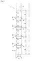
Fig. 2] Fig. 2 is an outline view showing the rotatory figure of the front portion of one embodiment of thedrill body 1 shown inFig. 1 , obtained by rotating thedrill body 1 on the axis O. (The shapes and the back tapers of cutting edge section 2 and guideportion 6 are simplified or emphasized in the views.) -
- 1
- DRILL BODY
- 2
- CUTTING EDGE SECTION
- 2A
- CUTTING EDGE
- 3
- FRONT FLANK
- 4
- CHIP EVACUATING FLUTE
- 5
- LAND
- 5A
- FIRST MARGIN
- 5B
- SECOND MARGIN
- 6
- GUIDE PORTION
- 6A
- MAXIMUM EXTERNAL DIAMETER PART OF
GUIDE PORTION 6 - O
- AXIS OF
DRILL BODY 1 - T
- DRILL ROTATIONAL DIRECTION
- D
- EXTERNAL DIAMETER AT
CUTTING EDGE 2A - R
- CURVATURE RADIUS OF CONVEX CURVE FORMED AT MAXIMUM
EXTERNAL DIAMETER PART 6A OFGUIDE PORTION 6 - L
- FLUTE LENGTH, NAMELY, LENGTH OF CHIP EVACUATION FLUTE, FROM FRONT OF CUTTING EDGE SECTION 2 TOWARD REAR SIDE IN DIRECTION OF AXIS O
-
Fig. 1 andFig. 2 show one embodiment in a case in which the present invention is applied to a solid carbide drill, i.e., a drill which is made solely of cemented carbide. In this embodiment, adrill body 1 is integrally formed as a single unit with a hard material such as the cemented carbide, has an almost columnar shape around an axis O as the center axis thereof, and has a shank in the rear portion not shown in the figures (the shank is provided in a portion that is further to the right than the portions shown inFigs. 1 and2 ). The shank is fixed to the spindle of a machining tool. Further, when rotating thedrill body 1 in a drill rotational direction T on the axis O, and then feeding thedrill body 1 along the axis O toward its front side (left side inFigs. 1 and2 ), cuttingedges 2A provided in a cutting edge section 2 located in the front side of thedrill body 1 bore a drilling hole into the workpiece. - Chip evacuating
flutes 4 are formed in the periphery of the front portion of thedrill body 1 shown inFigs 1 and2 . Thechip evacuating flutes 4 have a shape which is helical to the rear in the drill rotational direction T around the axis O, namely a right-handed helical tooth shape, and are formed rearward fromfront flanks 3 to the front end of the shank of thedrill body 1, for example. The cutting edges 2A are formed along ridge lines where thefront flanks 3 intersects with wall faces 4A which face in the drill rotational direction T.
Further, in the front portion of thedrill body 1, - the
chip evacuating flutes 4 as a pair are formed to be rotationally symmetrical with respect to the axis O at the angle of 180°; and - the cutting edges 2A as a pair are also formed to be rotationally symmetrical with respect to the axis O at the angle of 180°.
- Lands 5 are located between the
chip evacuating flutes 4 in the circumferential direction. Coolant holes 1A go through thedrill body 1 from the rear side of the shank to thefront flanks 3, are opened there, and are helical in the same manner as thechip evacuating flutes 4. - Further, in this embodiment,
first margins 5A intersected with the wall faces 4A are formed along rims at the forward side of the lands 5 in the drill rotational direction T. The wall faces 4A are in thechip evacuating flutes 4, and face in the drill rotational direction T.
On the other hand,second margins 5B intersected with the wall faces are formed along rims at the backward side (heel side) of the land 5 in the drill rotational direction T. The wall faces are adjacent to the backward side of the land 5 in the drill rotational direction T, and face in the opposite direction to the drill rotational direction T. A cross sectional view perpendicular to the axis O shows that: both of thefirst margins 5A and thesecond margins 5B have arc shapes in which the
axis 0 is their common center point and their external diameters are the same; and the external diameter of circumferences of the lands 5 between thefirst margins 5A and thesecond margins 5B is slightly smaller than the abovementioned external diameters of the circumferences of thefirst margins 5A and thesecond margins 5B. - Further, a back taper is provided in the cutting edge section 2 in the front side of the
drill body 1. The incline of the back taper is, as an example, within a range of 0.15/100 to 0.2/100. In other words, the aforementioned external diameters gradually decrease with the above incline from the ridge lines at thefront flanks 3 toward the rear side. Therefore, an external diameter D1 at the rear of the above cutting edge 2 is slightly smaller than an external diameter D at the cutting edges 2A. - Additionally, a
guide portion 6 is provided to the rear side of the cutting edge section 2. Theguide portion 6 has the maximum,external diameter part 6A at the front side thereof. The external diameter D2 at the maximumexternal diameter part 6A is larger than the external diameter D1 at the rear of the cutting edge 2, and is smaller than or equal to the external diameter D at the cutting edges 2A. The maximumexternal diameter part 6A of theguide portion 6 is shaped to be a smooth convex curve shape in a rotatory figure obtained by rotating it on the axis O.
In other words, in the front side of thedrill body 1, the section from thecutting edges 2A at the frontmost side thereof to theguide portion 6 having the external diameter D1, is the cutting edge section 2 in this embodiment. - In this embodiment, the first and
second margins guide portion 6 in the rotatory figure on the axis O are shown as a shape in which: - from the rear of the cutting edge section 2 to the maximum
external diameter part 6A, the shape is a convex arc with a radius R, and the external diameter thereof increases radially outward in proportion to the rear direction; - from the maximum
external diameter part 6A to a proximity point extremely close to it, the shape is still the convex arc with the radius R, and the external diameter thereof slightly decreases radially inward in proportion to the rear direction; - from the above proximity point toward the rear side, the shape is a straight line which is smoothly connected with the convex arc at the above proximity point and goes toward the rear side, and the external diameter thereof decreases radially inward in proportion to the rear direction.
- Therefore, in the
guide portion 6, a back taper is also provided in the first andsecond margins external diameter part 6A. The incline of the back taper is, as an example, within a range of 0.10/100 to 0.15/100. This incline is more gradual than that of the back taper provided in the cutting edge section 2 as previously mentioned. Also, in this embodiment, the above provided back taper makes an external diameter D3 at the rear of theguide portion 6 smaller than the external diameter D2 at the maximumexternal diameter part 6A. However, the external diameter D3 at the rear af theguide portion 6 is equal to the external diameter D1 at the rear of the cutting edge section 2 in this embodiment. - Further, in this embodiment, a plurality (four in
Fig. 2 ) ofsuch guide portions 6 is provided to the rear side of the cutting edge section 2 in a line along the axis O. Each of theguide portions 6 has the same shape and the same size in a rotatory figure obtained by rotating them on the axis O. Furthermore, in the rotatory figure, from the rear of theguide portion 6 with the external diameter D3, to the maximumexternal diameter part 6A of the nextrearward guide portion 6, the shape is the convex arc as previously mentioned and rises steeply radially outwardly. In other words, the external diameter thereof increases radially outwardly in proportion to the rear direction. Therefore, the maximumexternal diameter parts 6A are arranged at intervals of a constant length in the axis O direction. - The maximum
external diameter part 6A of therearmost guide portion 6 among theseplural guide portions 6 formed therein, is arranged at a position where the distance from the front of the cutting edge section 2 in the axis O is within a range of from L/3 to L/2. L means flute length L, i.e. the length of the drill body where thechip evacuating flutes 4 are formed from the frontmost part to the front of the shank of thedrill body 1 in the axis O direction. Thus, noguide portion 6 is arranged in a more rearward area than therearmost guide portion 6; thedrill body 1 has a cylindrical shape with the external diameter D3 in a rotatory figure obtained by rotating thedrill body 1 on the axis O as shown inFig. 2 ; and thechip evacuating flutes 4 formed in this shape extend to the front of the shank. - Further, in this embodiment, the ratio of L to D, i.e., the ratio L/D is more than 10. L means the flute length L, i.e. the length of the
chip evacuating flutes 4 from the front of the cutting edge section 2 in the axis 0 direction. D means the external diameter D at thecutting edge 2A. Also, the external diameter D at thecutting edge 2A is, as an example, within a range of from 0.1mm to 6mm. In other words, the drill in this embodiment is a solid drill (two-flute twist drill) with a small diameter and a long length.
Furthermore, the ratio of M to D, i.e., the ratio M/D is within a range of from 2 to 5. M is the length of the cutting edge section 2 in the axis O direction, and is shorter than the lead of thechip evacuating flutes 4. The lead means the axial advance of a leading edge in one turn around the circumference.
Also, the ratio of N to D, i.e., the ratio N/D is within a range of from 1 to 4. N is the length of eachguide portion 6 in the axis O direction, and is slightly smaller than M which is the length of the cutting edge section 2 in this embodiment. - Concerning the drill having the above construction, by feeding the
drill body 1 into a drilling hole to be bored, theguide portions 6 provided to the rear side of the cutting edge section 2 are inserted into the drilling hole following the cutting edge section 2; and each maximumexternal diameter part 6A slidingly contacts the inner wall face of the drilling hole.
On the other hand, in this sliding process, the inner wall face of the drilling hole supports the cutting edge section 2 to locate it at the center of the drilling hole. That is, the center axis of the drilling hole is coaxial with the axis O in the cutting edge section 2, and then the cutting edge section 2 is guided by this sliding process. Thus, the drilling hole can be bored levelly along the axis O even if a skipping rope phenomenon, in which a section of thedrill body 1 between theguide portion 6 and the shank vibrates and is deflected radially outward, occurs. In other words, the drilling hole can be prevented from curving, with the result that the linearity and the straightness of the drilling hole can be improved. - Additionally, concerning the drill having the above construction, the maximum
external diameter part 6A of theguide portion 6 is formed to show the smooth convex curve shape (convex arc shape) in a rotatory figure obtained by rotating it on the axis O. Thus, as previously mentioned, when the maximumexternal diameter part 6A is slidingly contacting the inner wall face of the drilling hole, the maximumexternal diameter part 6A does not bite the workpiece, and also does not damage the inner wall face of the drilling hole. The surface roughness of the inner wall face of the drilling hole can be improved. Therefore, in a case in which the drill is used for boring an injection hole in a fuel injection engine, the drill can form an injection hole which does not disturb the fuel injection and enables even combustion to be accelerated. - Additionally, the maximum
external diameter part 6A of theguide portion 6 has the smooth convex curve shape. Thus, when inserting theguide portion 6 into the drilling hole, this smooth convex curve shape prevents theguide portion 6 from being stuck therein and allows theguide portion 6 to slide smoothly. Therefore, theguide portion 6 can be smoothly inserted therein, and then can guide the cutting edge section 2 properly with a prompt movement.
Further when inserting theguide portion 6 into the drilling hole, this inserting operation may apply an impact thereto. Furthermore, when the maximumexternal diameter part 6A is slidingly contacting the inner wall face, this sliding contact also may apply a sliding load thereto. However, the smooth convex curve shape of theguide portion 6 can distribute this impact and load, and can also act as a buffer against them. Thus, this shape can prevent damage, for example a fracture, to theguide portion 6. - In this embodiment, the convex curve of the maximum
external diameter part 6A of theguide portion 6 in a rotatory figure obtained by rotating it on the axis O has a curvature radius R within the range of from 0.1mm to 0.5mm. This range enables the aforementioned advantages to be firmly established. If the curvature radius is so short as to be under this range, the maximum external diameter ofpart 6A becomes only a point rather than a curve, and then this point hits and contacts the inner wall face of the drilling hole in this state. Thus, there is a risk that the point will bite the inner wall face and damage it. On the other hand, if the curvature radius is so long as to be over this range, the contact length of the maximumexternal diameter part 6A with the inner wall face of the drilling hole becomes too long. Thus, while rotating thedrill body 1, the sliding load applied thereto increases. In particular with the drill having a small diameter as mentioned above, there is a risk that thedrill body 1 will break off. - In this embodiment:
- the two or
more guide portions 6 are provided to the rear side of the cutting edge section 2 in the axis O direction; - the maximum
external diameter parts 6A are arranged at each front side of theseguide portions 6; and - since back tapers are respectively provided further to the rear than each maximum
external diameter part 6A, the external diameter therein is smaller than that at each maximumexternal diameter part 6A. - Further, in this embodiment, in the above case in which the two or
more guide portions 6 are provided, the maximumexternal diameter part 6A of therearmost guide portion 6 among theseguide portions 6 is arranged at a position where the distance from the front of the cutting edge section 2 in the axis direction O is within L/2. L is the flute length, i.e. the length of thechip evacuating flutes 4 in the axis O direction. Thereby, this arrangement makes a rotational load caused by rotating thedrill body 1 decrease, whereby the cutting edge section 2 can be properly guided. - Once the
drill body 1 has been inserted into a drilling hole, and the depth of the hole has become greater than half of the flute length L, if a skipping rope phenomenon occurs further to the rear side, this phenomenon will not influence the cutting edge section 2 in the front side. If aguide portion 6 is arranged further to the rear than L/2, an increase in the rotational load caused bysuch guide portion 6 is a risk rather than the skipping rope phenomenon.
In this embodiment, since the two ormore guide portions 6 are arranged within L/2, namely, the half of the flute length L, from the front of the cutting edge section 2, theseguide portions 6 can ensure that the cutting edge section 2 is level. - In this embodiment, the maximum
external diameter part 6A of eachguide portion 6 has a convex arc shape in a rotatory figure obtained by rotating it on the axis O. Further, the external diameter of this convex arc shape increases radially outward in proportion to the rear direction from the rear of the cutting edge section 2 or from the rear of thenext guide portion 6 provided at the front. However, the shape in the rotatory figure is not limited to a convex arc shape, but most other smooth convex curves, for example a convex elliptical curve, are usable as the shape.
Further, in the rotatory figure, concerning a portion frontward adjacent to the maximumexternal diameter part 6A: from the rear of the cutting edge section 2 or from the rear of thenext guide portion 6 provided at the front, to the maximumexternal diameter part 6A; a linear shape or a concave curve shape with its external diameter increasing radially outward in proportion to the rear direction, is also usable for the shape around such a portion. - In this embodiment, the two or
more guide portions 6 are arranged at intervals of a constant length in the axis O direction. In addition to this arrangement, it is also possible to use variable intervals to arrange the two ormore guide portions 6.
For example, regarding theguide portions 6 positioned in the rear side of thedrill body 1, the maximumexternal diameter parts 6A thereof are arranged at intervals of a longer length in the axis O direction.
On the other hand, regarding theguide portions 6 close to the cutting edge section 2 in the front side of thedrill body 1, the maximumexternal diameter parts 6A thereof are arranged at intervals of a shorter length in the axis O direction. Thus, such variable intervals make the load decrease, and also make the guiding performance of the cutting edge section 2 increase noticeably. - Furthermore, in this embodiment, in the peripheries of the land of the
drill body 1,first margins 5A are provided to the forward sides of the lands 5 in the drill rotational direction T, and alsosecond margins 5B are provided to the backward sides of the lands 5 in the drill rotational direction T.
Thefirst margins 5A and thesecond margins 5B show the aforementioned convex curve shape in the rotatory figure, and this shape is then the shape of the maximumexternal diameter parts 6A in theguide portion 6.
For example, it is possible to use in a case in which: - only the
first margins 5A are provided; - the
guide portions 6 are formed on suchfirst margins 5A; and - the peripheries of the land 5 to the backward sides of the
first margins 5A in the drill rotational direction T are flanks which sink radially inward for thefirst margins 5A. - Further, for example, another case is also usable, in which:
- the entire peripheries of the land 5 from the
first margins 5A to thesecond margins 5B are margins which have an arc shape with its center as the axis O in a cross section perpendicular to the axis O; - the margins show a convex curve shape in the rotatory figure; and
- this shape is the shape of the maximum
external diameter parts 6A in theguide portion 6.
- the entire peripheries of the land 5 from the
- Regarding the drill of the present invention, the guide portion can guide the cutting edge section levelly in the axis direction, and the linearity of the drilling hole can be ensured. Also, the sliding contact of the guide portion prevents the inner wall face of the drilling hole from being damaged, with the result that the surface roughness of the inner wall face of the drilling hole can be improved.
For example, even if the drill is used for forming an injection hole of a fuel injection engine, the drill can bore levelly and precisely an extremely level injection hole, with the result that this injection hole enables even combustion in the combustion chamber to be accelerated without any disturbance in the fuel injection.
Claims (4)
- A drill comprising a drill body which has a stick shape and is rotatable on an axis; wherein:chip evacuating flutes are formed in a periphery of the drill body from front flanks toward a rear side;cutting edges are formed along ridge lines where the front flanks and wall faces intersect with each other;the wall faces are in the chip evacuating flutes and face in a drill rotational direction;the cutting edge section in a front side of the drill body has an external diameter smaller toward the rear side in the axis direction than an external diameter at the cutting edges;a guide portion is provided to the rear side of the cutting edge section;the guide portion has a maximum external diameter part on the front periphery side thereof;an external diameter at the maximum external diameter part is larger than the external diameter at the rear of the cutting edge section, and is smaller than or equal to the external diameter at the cutting edges; andthe maximum external diameter part of the guide portion shows a smooth convex curve shape in a rotatory figure obtained by rotating the drill body on the axis.
- A drill according to claim 1, wherein the convex curve of the maximum external diameter part of the guide portion has a curvature radius within a range of from 0.1mm to 0.5mm in a rotatory figure obtained by rotating it on the axis.
- A drill according to claim 1 or 2, wherein:an external diameter of the guide portion rearward in the axis direction is smaller than the external diameter at the maximum external diameter part; andtwo or more guide portions are provided to the rear side of the cutting edge section in the axis direction.
- A drill according to claim 1, 2 or 3, wherein:the two or more guide portions are provided to the rear side of the cutting edge section in the axis direction;a maximum external diameter part of the rearmost guide portion among these guide portions is arranged at a position where the distance from the front of the cutting edge section in the axis direction is within L/2; andL is the length of the chip evacuating flutes in the axis direction.
Applications Claiming Priority (2)
| Application Number | Priority Date | Filing Date | Title |
|---|---|---|---|
| JP2008232232A JP5035189B2 (en) | 2008-09-10 | 2008-09-10 | drill |
| PCT/JP2009/065468 WO2010029891A1 (en) | 2008-09-10 | 2009-09-04 | Drill |
Publications (3)
| Publication Number | Publication Date |
|---|---|
| EP2322303A1 true EP2322303A1 (en) | 2011-05-18 |
| EP2322303A4 EP2322303A4 (en) | 2012-11-07 |
| EP2322303B1 EP2322303B1 (en) | 2015-01-21 |
Family
ID=42005147
Family Applications (1)
| Application Number | Title | Priority Date | Filing Date |
|---|---|---|---|
| EP09813037.0A Not-in-force EP2322303B1 (en) | 2008-09-10 | 2009-09-04 | Drill |
Country Status (6)
| Country | Link |
|---|---|
| US (1) | US8876445B2 (en) |
| EP (1) | EP2322303B1 (en) |
| JP (1) | JP5035189B2 (en) |
| KR (1) | KR101230107B1 (en) |
| CN (1) | CN102149497B (en) |
| WO (1) | WO2010029891A1 (en) |
Cited By (1)
| Publication number | Priority date | Publication date | Assignee | Title |
|---|---|---|---|---|
| EP3599043A1 (en) * | 2018-07-23 | 2020-01-29 | Walter Ag | Deep hole drill |
Families Citing this family (15)
| Publication number | Priority date | Publication date | Assignee | Title |
|---|---|---|---|---|
| DE102011016960A1 (en) * | 2011-02-02 | 2012-08-02 | MAPAL Fabrik für Präzisionswerkzeuge Dr. Kress KG | Drilling tool and method of making holes |
| WO2014118881A1 (en) | 2013-01-29 | 2014-08-07 | オーエスジー株式会社 | Drill |
| DE102013004105A1 (en) * | 2013-03-11 | 2014-09-11 | Audi Ag | Drilling tool, in particular reamer |
| CN105050758A (en) | 2013-03-26 | 2015-11-11 | Osg株式会社 | Three-bladed drill with cutting fluid supply hole |
| USD765127S1 (en) | 2015-02-27 | 2016-08-30 | Samsung Electronics Co., Ltd. | Display screen or portion thereof with graphical user interface |
| JP6699836B2 (en) * | 2017-06-13 | 2020-05-27 | 住友電工ハードメタル株式会社 | Drill |
| CN107152242B (en) * | 2017-06-23 | 2023-10-20 | 浙江君悦标准件有限公司 | Chip-guiding type drill Kong Luogan |
| JP6797873B2 (en) * | 2018-09-19 | 2020-12-09 | 株式会社ビック・ツール | Drill for carbon fiber composite material |
| JP6727567B1 (en) * | 2019-06-26 | 2020-07-22 | 株式会社ビック・ツール | Carbon fiber composite drill |
| JP7052945B1 (en) * | 2021-03-08 | 2022-04-12 | 住友電工ハードメタル株式会社 | Drill |
| CN114472985B (en) * | 2021-12-03 | 2024-07-23 | 中航沈飞民用飞机有限责任公司 | Large-size high-precision step reaming tool with front and rear guide |
| CN116079828A (en) * | 2023-01-03 | 2023-05-09 | 广东鼎泰高科技术股份有限公司 | PCB drill bit with improved back drilling plug hole |
| WO2025177407A1 (en) * | 2024-02-20 | 2025-08-28 | 住友電工ハードメタル株式会社 | Drill and machining method |
| US12527581B1 (en) * | 2024-10-30 | 2026-01-20 | Marcus Abboud | Drill bit having roughness areas |
| CN120572045B (en) * | 2025-08-07 | 2025-10-28 | 山西春光锻造有限公司 | Drilling device for mold manufacturing |
Family Cites Families (22)
| Publication number | Priority date | Publication date | Assignee | Title |
|---|---|---|---|---|
| US2897695A (en) * | 1959-02-24 | 1959-08-04 | James C Winslow | Drill countersink bit |
| JPS48114379U (en) * | 1972-04-01 | 1973-12-27 | ||
| SU464398A1 (en) * | 1972-11-04 | 1975-03-25 | Тульский Политехнический Институт | Spiral drill |
| DE2541423A1 (en) * | 1975-09-17 | 1977-03-31 | Tiefbohr Technik Gmbh | Deep well boring tool - drills without deviation by flexible coupling between bit guide tube and drill string |
| JPS55150905A (en) * | 1979-05-11 | 1980-11-25 | Hitachi Ltd | Drill for high speed drilling |
| JPS5648416U (en) | 1979-09-18 | 1981-04-30 | ||
| SU965627A1 (en) * | 1981-01-19 | 1982-10-15 | Ордена Трудового Красного Знамени Ленинградский Институт Точной Механики И Оптики | Twist bit |
| JPS5840209A (en) * | 1981-09-02 | 1983-03-09 | Toshiaki Hosoi | Drill |
| SU1103959A1 (en) * | 1983-02-02 | 1984-07-23 | Skochko Evgenij V | Spiral drill |
| SU1668054A1 (en) * | 1989-01-12 | 1991-08-07 | Саратовский политехнический институт | Twist bit |
| JP2963736B2 (en) * | 1990-07-17 | 1999-10-18 | 東芝タンガロイ株式会社 | Drilling tool |
| DE4028261A1 (en) * | 1990-08-06 | 1992-02-13 | Fischer Artur Werke Gmbh | DRILLS FOR PRODUCING CYLINDRICAL DRILL HOLES |
| DE9103015U1 (en) * | 1991-03-13 | 1992-07-09 | fischerwerke Artur Fischer GmbH & Co KG, 7244 Waldachtal | Drills for producing holes with undercut |
| JPH0550313A (en) * | 1991-08-19 | 1993-03-02 | Kobe Steel Ltd | Drill |
| GB9310029D0 (en) * | 1993-05-15 | 1993-06-30 | Stewart Arthur D | Improvements in or relating to drill pipe |
| US5697640A (en) | 1996-02-16 | 1997-12-16 | Trw Vehicle Safety Systems Inc. | Pleated air bag |
| US5807039A (en) * | 1997-02-13 | 1998-09-15 | Credo Tool Company | Drill bit |
| DE19807429A1 (en) * | 1998-02-23 | 1999-08-26 | Mueller | Precision boring bit with two cutting edges |
| JP2003340623A (en) * | 2002-05-28 | 2003-12-02 | Nissan Motor Co Ltd | Drill |
| CN100417479C (en) | 2004-03-17 | 2008-09-10 | 钴碳化钨硬质合金公司 | twist drill |
| JP4843317B2 (en) * | 2006-01-26 | 2011-12-21 | 住友電工ハードメタル株式会社 | Long drill with guide |
| DE102006062429A1 (en) * | 2006-12-27 | 2008-07-03 | Günther & Co. GmbH | Deep hole drill, has supporting rib with radial outer surface defining radius, which is larger than radius of cutting groove section, where radius of outer surface is axially adjacent to supporting rib |
-
2008
- 2008-09-10 JP JP2008232232A patent/JP5035189B2/en not_active Expired - Fee Related
-
2009
- 2009-09-04 CN CN200980135915.0A patent/CN102149497B/en not_active Expired - Fee Related
- 2009-09-04 WO PCT/JP2009/065468 patent/WO2010029891A1/en not_active Ceased
- 2009-09-04 US US12/998,020 patent/US8876445B2/en not_active Expired - Fee Related
- 2009-09-04 KR KR1020117005605A patent/KR101230107B1/en not_active Expired - Fee Related
- 2009-09-04 EP EP09813037.0A patent/EP2322303B1/en not_active Not-in-force
Cited By (1)
| Publication number | Priority date | Publication date | Assignee | Title |
|---|---|---|---|---|
| EP3599043A1 (en) * | 2018-07-23 | 2020-01-29 | Walter Ag | Deep hole drill |
Also Published As
| Publication number | Publication date |
|---|---|
| JP5035189B2 (en) | 2012-09-26 |
| US8876445B2 (en) | 2014-11-04 |
| US20110211924A1 (en) | 2011-09-01 |
| EP2322303A4 (en) | 2012-11-07 |
| CN102149497B (en) | 2015-01-28 |
| WO2010029891A1 (en) | 2010-03-18 |
| JP2010064186A (en) | 2010-03-25 |
| KR101230107B1 (en) | 2013-02-05 |
| EP2322303B1 (en) | 2015-01-21 |
| KR20110055612A (en) | 2011-05-25 |
| CN102149497A (en) | 2011-08-10 |
Similar Documents
| Publication | Publication Date | Title |
|---|---|---|
| EP2322303B1 (en) | Drill | |
| KR100838767B1 (en) | Twist drill | |
| US7789599B2 (en) | Drill | |
| US9156094B2 (en) | Step drill for wood | |
| JP2006272503A (en) | Insert removable drill | |
| JP2012223830A (en) | Drill | |
| CN102438786A (en) | tap with drill bit | |
| CN104870131A (en) | Twist drill | |
| KR20150035443A (en) | A deep hole drill tool | |
| US20180056403A1 (en) | Drill | |
| JP2002120220A (en) | Rock drill | |
| CN102470452A (en) | Drill | |
| US20030108396A1 (en) | Thread cutting tool having cutting teeth with stepped undercut flanks | |
| US20110067927A1 (en) | Drill Head for Deep-Hole Drilling | |
| WO2002040206A1 (en) | Small drill | |
| JP2009255211A (en) | Female screw machining tool and female screw machining method using it | |
| EP3957421A1 (en) | Drill | |
| US8132989B2 (en) | Drill | |
| CN201720501U (en) | Guide-type step expanding drill | |
| JP2010099815A (en) | Cutting insert | |
| JP4015034B2 (en) | Small diameter drill | |
| JP4843317B2 (en) | Long drill with guide | |
| JP5052399B2 (en) | Internal thread processing method | |
| JP2008023607A (en) | Gun drill and drill body attached to it | |
| KR20170021520A (en) | Spiral Plute Tap |
Legal Events
| Date | Code | Title | Description |
|---|---|---|---|
| PUAI | Public reference made under article 153(3) epc to a published international application that has entered the european phase |
Free format text: ORIGINAL CODE: 0009012 |
|
| 17P | Request for examination filed |
Effective date: 20110223 |
|
| AK | Designated contracting states |
Kind code of ref document: A1 Designated state(s): AT BE BG CH CY CZ DE DK EE ES FI FR GB GR HR HU IE IS IT LI LT LU LV MC MK MT NL NO PL PT RO SE SI SK SM TR |
|
| AX | Request for extension of the european patent |
Extension state: AL BA RS |
|
| DAX | Request for extension of the european patent (deleted) | ||
| REG | Reference to a national code |
Ref country code: DE Ref legal event code: R079 Ref document number: 602009029148 Country of ref document: DE Free format text: PREVIOUS MAIN CLASS: B23B0051000000 Ipc: B23B0051020000 |
|
| A4 | Supplementary search report drawn up and despatched |
Effective date: 20121005 |
|
| RIC1 | Information provided on ipc code assigned before grant |
Ipc: B23B 51/02 20060101AFI20120928BHEP |
|
| 17Q | First examination report despatched |
Effective date: 20130903 |
|
| GRAP | Despatch of communication of intention to grant a patent |
Free format text: ORIGINAL CODE: EPIDOSNIGR1 |
|
| INTG | Intention to grant announced |
Effective date: 20140616 |
|
| GRAS | Grant fee paid |
Free format text: ORIGINAL CODE: EPIDOSNIGR3 |
|
| GRAP | Despatch of communication of intention to grant a patent |
Free format text: ORIGINAL CODE: EPIDOSNIGR1 |
|
| INTG | Intention to grant announced |
Effective date: 20141022 |
|
| GRAA | (expected) grant |
Free format text: ORIGINAL CODE: 0009210 |
|
| AK | Designated contracting states |
Kind code of ref document: B1 Designated state(s): AT BE BG CH CY CZ DE DK EE ES FI FR GB GR HR HU IE IS IT LI LT LU LV MC MK MT NL NO PL PT RO SE SI SK SM TR |
|
| REG | Reference to a national code |
Ref country code: GB Ref legal event code: FG4D |
|
| REG | Reference to a national code |
Ref country code: CH Ref legal event code: EP |
|
| REG | Reference to a national code |
Ref country code: IE Ref legal event code: FG4D |
|
| REG | Reference to a national code |
Ref country code: DE Ref legal event code: R096 Ref document number: 602009029148 Country of ref document: DE Effective date: 20150305 |
|
| REG | Reference to a national code |
Ref country code: AT Ref legal event code: REF Ref document number: 708923 Country of ref document: AT Kind code of ref document: T Effective date: 20150315 |
|
| REG | Reference to a national code |
Ref country code: NL Ref legal event code: VDEP Effective date: 20150121 |
|
| REG | Reference to a national code |
Ref country code: AT Ref legal event code: MK05 Ref document number: 708923 Country of ref document: AT Kind code of ref document: T Effective date: 20150121 |
|
| REG | Reference to a national code |
Ref country code: LT Ref legal event code: MG4D |
|
| PG25 | Lapsed in a contracting state [announced via postgrant information from national office to epo] |
Ref country code: LT Free format text: LAPSE BECAUSE OF FAILURE TO SUBMIT A TRANSLATION OF THE DESCRIPTION OR TO PAY THE FEE WITHIN THE PRESCRIBED TIME-LIMIT Effective date: 20150121 Ref country code: FI Free format text: LAPSE BECAUSE OF FAILURE TO SUBMIT A TRANSLATION OF THE DESCRIPTION OR TO PAY THE FEE WITHIN THE PRESCRIBED TIME-LIMIT Effective date: 20150121 Ref country code: HR Free format text: LAPSE BECAUSE OF FAILURE TO SUBMIT A TRANSLATION OF THE DESCRIPTION OR TO PAY THE FEE WITHIN THE PRESCRIBED TIME-LIMIT Effective date: 20150121 Ref country code: SE Free format text: LAPSE BECAUSE OF FAILURE TO SUBMIT A TRANSLATION OF THE DESCRIPTION OR TO PAY THE FEE WITHIN THE PRESCRIBED TIME-LIMIT Effective date: 20150121 Ref country code: ES Free format text: LAPSE BECAUSE OF FAILURE TO SUBMIT A TRANSLATION OF THE DESCRIPTION OR TO PAY THE FEE WITHIN THE PRESCRIBED TIME-LIMIT Effective date: 20150121 Ref country code: NO Free format text: LAPSE BECAUSE OF FAILURE TO SUBMIT A TRANSLATION OF THE DESCRIPTION OR TO PAY THE FEE WITHIN THE PRESCRIBED TIME-LIMIT Effective date: 20150421 Ref country code: BG Free format text: LAPSE BECAUSE OF FAILURE TO SUBMIT A TRANSLATION OF THE DESCRIPTION OR TO PAY THE FEE WITHIN THE PRESCRIBED TIME-LIMIT Effective date: 20150421 |
|
| PG25 | Lapsed in a contracting state [announced via postgrant information from national office to epo] |
Ref country code: NL Free format text: LAPSE BECAUSE OF FAILURE TO SUBMIT A TRANSLATION OF THE DESCRIPTION OR TO PAY THE FEE WITHIN THE PRESCRIBED TIME-LIMIT Effective date: 20150121 Ref country code: AT Free format text: LAPSE BECAUSE OF FAILURE TO SUBMIT A TRANSLATION OF THE DESCRIPTION OR TO PAY THE FEE WITHIN THE PRESCRIBED TIME-LIMIT Effective date: 20150121 Ref country code: LV Free format text: LAPSE BECAUSE OF FAILURE TO SUBMIT A TRANSLATION OF THE DESCRIPTION OR TO PAY THE FEE WITHIN THE PRESCRIBED TIME-LIMIT Effective date: 20150121 Ref country code: PL Free format text: LAPSE BECAUSE OF FAILURE TO SUBMIT A TRANSLATION OF THE DESCRIPTION OR TO PAY THE FEE WITHIN THE PRESCRIBED TIME-LIMIT Effective date: 20150121 Ref country code: GR Free format text: LAPSE BECAUSE OF FAILURE TO SUBMIT A TRANSLATION OF THE DESCRIPTION OR TO PAY THE FEE WITHIN THE PRESCRIBED TIME-LIMIT Effective date: 20150422 Ref country code: IS Free format text: LAPSE BECAUSE OF FAILURE TO SUBMIT A TRANSLATION OF THE DESCRIPTION OR TO PAY THE FEE WITHIN THE PRESCRIBED TIME-LIMIT Effective date: 20150521 |
|
| REG | Reference to a national code |
Ref country code: DE Ref legal event code: R097 Ref document number: 602009029148 Country of ref document: DE |
|
| PG25 | Lapsed in a contracting state [announced via postgrant information from national office to epo] |
Ref country code: RO Free format text: LAPSE BECAUSE OF FAILURE TO SUBMIT A TRANSLATION OF THE DESCRIPTION OR TO PAY THE FEE WITHIN THE PRESCRIBED TIME-LIMIT Effective date: 20150121 Ref country code: DK Free format text: LAPSE BECAUSE OF FAILURE TO SUBMIT A TRANSLATION OF THE DESCRIPTION OR TO PAY THE FEE WITHIN THE PRESCRIBED TIME-LIMIT Effective date: 20150121 Ref country code: SK Free format text: LAPSE BECAUSE OF FAILURE TO SUBMIT A TRANSLATION OF THE DESCRIPTION OR TO PAY THE FEE WITHIN THE PRESCRIBED TIME-LIMIT Effective date: 20150121 Ref country code: CZ Free format text: LAPSE BECAUSE OF FAILURE TO SUBMIT A TRANSLATION OF THE DESCRIPTION OR TO PAY THE FEE WITHIN THE PRESCRIBED TIME-LIMIT Effective date: 20150121 Ref country code: EE Free format text: LAPSE BECAUSE OF FAILURE TO SUBMIT A TRANSLATION OF THE DESCRIPTION OR TO PAY THE FEE WITHIN THE PRESCRIBED TIME-LIMIT Effective date: 20150121 |
|
| PLBE | No opposition filed within time limit |
Free format text: ORIGINAL CODE: 0009261 |
|
| STAA | Information on the status of an ep patent application or granted ep patent |
Free format text: STATUS: NO OPPOSITION FILED WITHIN TIME LIMIT |
|
| 26N | No opposition filed |
Effective date: 20151022 |
|
| PG25 | Lapsed in a contracting state [announced via postgrant information from national office to epo] |
Ref country code: SI Free format text: LAPSE BECAUSE OF FAILURE TO SUBMIT A TRANSLATION OF THE DESCRIPTION OR TO PAY THE FEE WITHIN THE PRESCRIBED TIME-LIMIT Effective date: 20150121 |
|
| PG25 | Lapsed in a contracting state [announced via postgrant information from national office to epo] |
Ref country code: LU Free format text: LAPSE BECAUSE OF FAILURE TO SUBMIT A TRANSLATION OF THE DESCRIPTION OR TO PAY THE FEE WITHIN THE PRESCRIBED TIME-LIMIT Effective date: 20150904 Ref country code: MC Free format text: LAPSE BECAUSE OF FAILURE TO SUBMIT A TRANSLATION OF THE DESCRIPTION OR TO PAY THE FEE WITHIN THE PRESCRIBED TIME-LIMIT Effective date: 20150121 |
|
| REG | Reference to a national code |
Ref country code: CH Ref legal event code: PL |
|
| PG25 | Lapsed in a contracting state [announced via postgrant information from national office to epo] |
Ref country code: BE Free format text: LAPSE BECAUSE OF FAILURE TO SUBMIT A TRANSLATION OF THE DESCRIPTION OR TO PAY THE FEE WITHIN THE PRESCRIBED TIME-LIMIT Effective date: 20150121 |
|
| REG | Reference to a national code |
Ref country code: IE Ref legal event code: MM4A |
|
| PG25 | Lapsed in a contracting state [announced via postgrant information from national office to epo] |
Ref country code: IE Free format text: LAPSE BECAUSE OF NON-PAYMENT OF DUE FEES Effective date: 20150904 Ref country code: CH Free format text: LAPSE BECAUSE OF NON-PAYMENT OF DUE FEES Effective date: 20150930 Ref country code: LI Free format text: LAPSE BECAUSE OF NON-PAYMENT OF DUE FEES Effective date: 20150930 |
|
| REG | Reference to a national code |
Ref country code: FR Ref legal event code: PLFP Year of fee payment: 8 |
|
| PG25 | Lapsed in a contracting state [announced via postgrant information from national office to epo] |
Ref country code: MT Free format text: LAPSE BECAUSE OF FAILURE TO SUBMIT A TRANSLATION OF THE DESCRIPTION OR TO PAY THE FEE WITHIN THE PRESCRIBED TIME-LIMIT Effective date: 20150121 |
|
| PG25 | Lapsed in a contracting state [announced via postgrant information from national office to epo] |
Ref country code: HU Free format text: LAPSE BECAUSE OF FAILURE TO SUBMIT A TRANSLATION OF THE DESCRIPTION OR TO PAY THE FEE WITHIN THE PRESCRIBED TIME-LIMIT; INVALID AB INITIO Effective date: 20090904 Ref country code: SM Free format text: LAPSE BECAUSE OF FAILURE TO SUBMIT A TRANSLATION OF THE DESCRIPTION OR TO PAY THE FEE WITHIN THE PRESCRIBED TIME-LIMIT Effective date: 20150121 |
|
| PG25 | Lapsed in a contracting state [announced via postgrant information from national office to epo] |
Ref country code: CY Free format text: LAPSE BECAUSE OF FAILURE TO SUBMIT A TRANSLATION OF THE DESCRIPTION OR TO PAY THE FEE WITHIN THE PRESCRIBED TIME-LIMIT Effective date: 20150121 |
|
| PG25 | Lapsed in a contracting state [announced via postgrant information from national office to epo] |
Ref country code: TR Free format text: LAPSE BECAUSE OF FAILURE TO SUBMIT A TRANSLATION OF THE DESCRIPTION OR TO PAY THE FEE WITHIN THE PRESCRIBED TIME-LIMIT Effective date: 20150121 |
|
| REG | Reference to a national code |
Ref country code: FR Ref legal event code: PLFP Year of fee payment: 9 |
|
| PG25 | Lapsed in a contracting state [announced via postgrant information from national office to epo] |
Ref country code: MK Free format text: LAPSE BECAUSE OF FAILURE TO SUBMIT A TRANSLATION OF THE DESCRIPTION OR TO PAY THE FEE WITHIN THE PRESCRIBED TIME-LIMIT Effective date: 20150121 Ref country code: PT Free format text: LAPSE BECAUSE OF FAILURE TO SUBMIT A TRANSLATION OF THE DESCRIPTION OR TO PAY THE FEE WITHIN THE PRESCRIBED TIME-LIMIT Effective date: 20150121 |
|
| REG | Reference to a national code |
Ref country code: FR Ref legal event code: PLFP Year of fee payment: 10 |
|
| PGFP | Annual fee paid to national office [announced via postgrant information from national office to epo] |
Ref country code: FR Payment date: 20180925 Year of fee payment: 10 Ref country code: DE Payment date: 20180920 Year of fee payment: 10 Ref country code: IT Payment date: 20180925 Year of fee payment: 10 |
|
| PGFP | Annual fee paid to national office [announced via postgrant information from national office to epo] |
Ref country code: GB Payment date: 20180919 Year of fee payment: 10 |
|
| REG | Reference to a national code |
Ref country code: DE Ref legal event code: R119 Ref document number: 602009029148 Country of ref document: DE |
|
| PG25 | Lapsed in a contracting state [announced via postgrant information from national office to epo] |
Ref country code: DE Free format text: LAPSE BECAUSE OF NON-PAYMENT OF DUE FEES Effective date: 20200401 |
|
| PG25 | Lapsed in a contracting state [announced via postgrant information from national office to epo] |
Ref country code: IT Free format text: LAPSE BECAUSE OF NON-PAYMENT OF DUE FEES Effective date: 20190904 |
|
| GBPC | Gb: european patent ceased through non-payment of renewal fee |
Effective date: 20190904 |
|
| PG25 | Lapsed in a contracting state [announced via postgrant information from national office to epo] |
Ref country code: FR Free format text: LAPSE BECAUSE OF NON-PAYMENT OF DUE FEES Effective date: 20190930 Ref country code: GB Free format text: LAPSE BECAUSE OF NON-PAYMENT OF DUE FEES Effective date: 20190904 |