EP2321715B1 - Kupplungshöheneinstellung in einer vorrichtung für optische verfolgung - Google Patents
Kupplungshöheneinstellung in einer vorrichtung für optische verfolgung Download PDFInfo
- Publication number
- EP2321715B1 EP2321715B1 EP09812247.6A EP09812247A EP2321715B1 EP 2321715 B1 EP2321715 B1 EP 2321715B1 EP 09812247 A EP09812247 A EP 09812247A EP 2321715 B1 EP2321715 B1 EP 2321715B1
- Authority
- EP
- European Patent Office
- Prior art keywords
- tracking
- clutch
- light
- height
- aperture
- Prior art date
- Legal status (The legal status is an assumption and is not a legal conclusion. Google has not performed a legal analysis and makes no representation as to the accuracy of the status listed.)
- Active
Links
Images






Classifications
-
- G—PHYSICS
- G06—COMPUTING OR CALCULATING; COUNTING
- G06F—ELECTRIC DIGITAL DATA PROCESSING
- G06F3/00—Input arrangements for transferring data to be processed into a form capable of being handled by the computer; Output arrangements for transferring data from processing unit to output unit, e.g. interface arrangements
- G06F3/01—Input arrangements or combined input and output arrangements for interaction between user and computer
- G06F3/03—Arrangements for converting the position or the displacement of a member into a coded form
- G06F3/033—Pointing devices displaced or positioned by the user, e.g. mice, trackballs, pens or joysticks; Accessories therefor
- G06F3/038—Control and interface arrangements therefor, e.g. drivers or device-embedded control circuitry
-
- G—PHYSICS
- G06—COMPUTING OR CALCULATING; COUNTING
- G06F—ELECTRIC DIGITAL DATA PROCESSING
- G06F3/00—Input arrangements for transferring data to be processed into a form capable of being handled by the computer; Output arrangements for transferring data from processing unit to output unit, e.g. interface arrangements
- G06F3/01—Input arrangements or combined input and output arrangements for interaction between user and computer
- G06F3/03—Arrangements for converting the position or the displacement of a member into a coded form
- G06F3/0304—Detection arrangements using opto-electronic means
- G06F3/0317—Detection arrangements using opto-electronic means in co-operation with a patterned surface, e.g. absolute position or relative movement detection for an optical mouse or pen positioned with respect to a coded surface
-
- G—PHYSICS
- G06—COMPUTING OR CALCULATING; COUNTING
- G06F—ELECTRIC DIGITAL DATA PROCESSING
- G06F3/00—Input arrangements for transferring data to be processed into a form capable of being handled by the computer; Output arrangements for transferring data from processing unit to output unit, e.g. interface arrangements
- G06F3/01—Input arrangements or combined input and output arrangements for interaction between user and computer
- G06F3/03—Arrangements for converting the position or the displacement of a member into a coded form
- G06F3/033—Pointing devices displaced or positioned by the user, e.g. mice, trackballs, pens or joysticks; Accessories therefor
- G06F3/0354—Pointing devices displaced or positioned by the user, e.g. mice, trackballs, pens or joysticks; Accessories therefor with detection of two-dimensional [2D] relative movements between the device, or an operating part thereof, and a plane or surface, e.g. 2D mice, trackballs, pens or pucks
- G06F3/03543—Mice or pucks
Definitions
- Computer input devices such as mice have been the mainstay device for most users interacting with a computing system.
- the mouse as the principal computing navigation device, has evolved over recent years from the basic tethered single function mechanical pointing device using a surface contact ball to the wireless optical multi-function input device of today that can employ laser/LED light sources and image sensors.
- the control of inadvertent pointer tracking was solved in a straightforward way with the ball mouse, since when the user clutched the mouse from the tracking surface, the ball simply dropped away from the internal contract-driven linear tracking mechanism.
- optical "sophistication" come additional problems such as processing reflected light from a variety of different navigation (tracking) surfaces and controlling tracking when the mouse leaves the tracking surface.
- Clutch height is a parameter that must be addressed for control in an optical mouse. As the mouse is lifted off of the tracking surface, it is desirable to cease mouse tracking after a specified distance has been reached. Put differently, the user does not want to see the mouse pointer moving randomly on the display. This problem becomes particularly noteworthy for computer users that demand precise tracking control when moving the mouse off the tracking surface, such as for computers gamers, CAD operators, for example.
- US 2005/02674531 A1 discloses an optical pointing device with variable focus.
- US 2006/0091298 A1 discloses tracking separation between an object and a surface using a reducing structure.
- US 2007/0008286 A1 discloses optical displacement detection over varied surfaces.
- WO 2007/005006 A1 discloses a system for adjusting depth of view in an optical sensor.
- the disclosed architecture includes optical, electrical, mechanical, and/or software techniques for adjusting the clutch height of a device relative to a tracking surface by setting a threshold on the clutch height.
- a tracking assembly for tracking movement of the device relative to a tracking surface by emitting incident light on the tracking surface and sensing reflected light received from the tracking surface using an image sensor.
- An obfuscation component reduces an amount of the reflected light sensed by the image sensor in response to clutch of the device from the tracking surface.
- the obfuscation component provides an aperture mechanically configured to occlude a portion of the reflected light to the image sensor.
- a firmware component provides software and algorithms of which one or more parameters can be changed for adjusting the clutch-height threshold.
- Other techniques are also disclosed that facilitate user customization of the clutch-height parameters via a user interface, for example.
- the instant architecture discloses techniques for managing clutch height in an optical navigational device such as a computer mouse.
- one or more features can be molded into the bottom case of the mouse that limit the clutch height, for example the "D-shaped" optical port, by occluding portions of the reflected light on an image sensor that is received from the tracking surface.
- portions of the incident light can be occluded. It is to be understood that the term "occlude” and forms thereof as used herein are intended to mean “some or all" of the light can be blocked.
- the mouse can include firmware controlled algorithm adjustments to change the autocorrelation or cross-correlation threshold heights.
- a threshold can be placed on the z-axis height tracking distance using the mechanical feature, such as a knife-edge (the straight portion of the "D" shaped aperture), to impose a shadow across the mouse image sensor.
- the aperture can be custom designed to occlude a portion of the emitted light from an LED, for example.
- the mechanical feature can be made adjustable for mechanically tolerancing of the optical device to preserve tracking while on-surface, and cease tracking off-surface.
- An illumination lens design is provided that tailors the emitted light in such a way as to cease tracking upon device lift-off.
- An adjustable bottom case aperture (or "slit width") allows the user to mechanically adjustable the clutch height by enlarging the aperture or making the aperture smaller. This can be relevant especially in gaming mouse products. Additionally, a software adjustable autocorrelation height threshold is facilitated that trades-off or limits tracking performance on some surfaces for user adjustable clutch height on other surfaces.
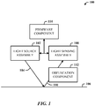
- FIG. 1 illustrates a clutch-height adjustment system 100 in accordance with the disclosed architecture.
- the system 100 includes a light source assembly 102 for emitting incident light 104 on a tracking surface 106, and light sensing assembly 108 for receiving reflected light 110 from the tracking surface 106.
- the light source assembly 102 and light sensing assembly 108 are employed in a device (e.g., mouse), for example, for tracking movement of the device relative to the tracking surface 106.
- a device e.g., mouse
- the system 100 also includes an obfuscation component 112 for reducing the amount of light sensed by the light sensing assembly 108 in response to clutch of the device from the tracking surface 106.
- the obfuscation component 112 can include at least one of a bottom case aperture, a bottom case feature, a diffractive optic illumination lens, or an illumination lens with total internal reflection geometry.
- a technique for reducing the light sensed by the light sensing assembly 108 via the obfuscation component 112 can be mechanical means for occluding the reflected light (to impose a shadow on the light sensing assembly 108), such as an aperture configuration on the base housing of the device in which the system 100 is employed.
- the aperture can be the same optical port in the housing through which the incident light 104 is emitted onto the tracking surface 106 and through which the reflected light 110 is received onto the light sensing assembly 108.
- the aperture can be designed according to dimensions that begin partial blocking of the reflected light 110 that reaches the light sensing assembly 108 when the device is lifted from the tracking surface 106, thereby imposing a shadow on the sensing assembly 108.
- the obfuscation component 112 can also be employed as a mechanical and suitably designed tab or other similar type of oblation internal to the device housing to obtain the similar effect of reducing the amount of reflected light 110 that reaches the light sensing assembly 108 when the height of the device relative to the tracking surface 106 increases.
- the light source assembly 102 can include a light emitting element such as an LED (light emitting diode), laser source, and one or more lenses and/or other optical components, power switching assembly (e.g., circuits) for turning the light emitting element on or off, etc., for directing the incident light 104 to the tracking surface 106.
- a light emitting element such as an LED (light emitting diode), laser source, and one or more lenses and/or other optical components
- power switching assembly e.g., circuits
- the light sensing assembly 108 can include an image sensor (e.g., CCD-charge coupled device or CMOS) and, one or more lenses and/or other optical components for directing the reflected light 110 to the image sensor.
- an image sensor e.g., CCD-charge coupled device or CMOS
- lenses and/or other optical components for directing the reflected light 110 to the image sensor.
- the system 100 can also include a firmware component 114 for onboard operations related to light integration on the image sensor for comparison to clutch-height threshold settings, controlling power to the light emitting element, supporting wire/wireless communications, supporting multi-function buttons and commands of the device in which the system 100 is employed, and so on.
- the system 100 can achieve the desired functionality and control using opto-electro-mechanical components, firmware control, and/or a software interface that facilitates vendor adjustable, as well as user-customizable system parameters.
- FIG. 2 illustrates an alternative embodiment of a clutch-height adjustment system 200 in a device 202 that employs an aperture 204 to reduce the reflected light 110 on an image sensor 206 during device lift-off from the tracking surface 106.
- the system 200 includes a tracking assembly 208 for tracking movement of the device 202 relative to the tracking surface 106 by emitting the incident light 104 on the tracking surface 106 and sensing the reflected light 110 received from the tracking surface 106 using the image sensor 206 as part of the light sensing assembly 108.
- the light source assembly 102, light sensing assembly 108, and firmware component 114 are shown as part of the tracking assembly 208.
- the obfuscation component 112 can also be considered part of the tracking assembly 208.
- the light source assembly 102 can include an LED as a light source 210.
- LED as a light source 210.
- the LED illumination emits a much more expansive beam than the laser (more focused) facilitating the ability to control and sculpt the light (incident and reflected) using opto-electro-mechanical device features to control the clutch height.
- the obfuscation component 112 is provided for reducing the amount of the reflected light 110 sensed by the image sensor 206 in response to clutch of the device 202 from the tracking surface 106.
- the obfuscation component 112 includes the aperture 204 which is mechanically configured to occlude a portion of the reflected light 110 to the image sensor 206.
- the tracking assembly 208 can also include the firmware component 114 for adjusting one or more parameters of an algorithm employed for computing a clutch-height threshold.
- the tracking height (TH) is illustrated as the distance between the device (e.g., housing base) and the tracking surface 106. This can mean that the device 202 contacts the surface 106 or is proximate to the surface 106 when operating in the tracking mode.
- the clutch height (CH) is depicted as the tracking height plus some additional distance D such that when the device 202 is lifted off the tracking surface 106, there is provided the additional distance D of travel to the clutch height before tracking mode is turned off. This facilitates more leisurely use of the device 202, and hence, a more positive user experience, where the average user does not need to be overly concerned with maintain the device 202 in contact with the tracking surface 106.
- a power user e.g., a gamer
- a power user e.g., a gamer
- a clutch height may be lowered closer to the tracking surface 106, once the clutch height is reached, tracking mode is resumed.
- the firmware component 114 In support of customized adjustment of the clutch height, the firmware component 114 exposes the one or more correlation parameters for adjustment via a user interface. This can also include the adjustment of parameters for different tracking surfaces (e.g., carpet, more reflective surfaces, less reflective surfaces, gaming surfaces, etc.).
- the firmware component 114 can also report tracking data (e.g., autocorrelation data, cross-correlation data, etc.), clutch-height data (e.g., threshold level), and other information (e.g., model, firmware version, etc.) to a single-purpose application (e.g., a gadget) for presentation and viewing by a user.
- tracking data e.g., autocorrelation data, cross-correlation data, etc.
- clutch-height data e.g., threshold level
- other information e.g., model, firmware version, etc.
- the aperture 204 can include an edge (e.g., the straight edge in a "D" shaped aperture) that increasingly occludes the reflected light 110 to the image sensor 206 as the distance D from the tracking height increases.
- the tracking assembly 208 disables tracking of the device movement when the distance D reaches the clutch-height threshold.
- the obfuscation component 112 increasingly occludes the reflected light 110 as the distance increases between the device and the tracking surface 106 (when starting from a surface contact position), and decreasingly occludes the reflected light 110 as the distance between the device and the tracking surface 106 decreases.
- the obfuscation component 112 increasingly occludes the reflected light 110 as the distance D increases between the device tracking height and the tracking surface 106 (when starting from a surface contact position), and decreasingly occludes the reflected light 110 as the distance between the device and the tracking surface 106 decreases.
- the light sensing assembly 108 disables the tracking mode when the increasing distance exceeds the clutch-height threshold, and enables the tracking mode when the decreasing distance meets and moves below the clutch-height threshold.
- FIG. 3 illustrates an alternative example of a clutch-height adjustment system 300 where the obfuscation component 112 can be employed in the incident light path to tailor the incident light 104 based on lift-off of the tracking surface 106.
- a mechanical tilt component can be employed to variably and partially occlude the incident light 104 based on movement of the device off from the tracking surface 106.
- the amount of reflected light 110 is then reduced by the partial occlusion of the incident light 104, thereby reducing the overall amount of light to the light sensing assembly 108 (e.g., image sensor).
- the clutch height is determined to have been reached and the tracking functionality turned off. This can be achieved using opto-electro-mechanical components with firmware control, and user-adjustable software interface.
- This alternative example can also include including features in the incident path lens(es).
- the obfuscation component 112 when the device experiences lift-off from the tracking surface 106, the obfuscation component 112 includes a lens, diffractive optical element or total-internal reflection geometry in the incident path that comprises a feature that variably diverts portions of the emitted light away from the tracking surface 106 based on the corresponding increase in lift distance, thereby reducing the amount of reflected light 110 sensed by the light sensing assembly 108.
- tracking mode is disabled.
- One such feature can be to design the lens to shape the illumination profile of the incident light into a D-shape, other than circular, such that during lift-off, the emitted light is increasingly directed to the straight vertical portion of the "D" causing diversion of a corresponding amount of the incident light 104 away from the light sensing assembly 108. Again, when the amount of light sensed by the sensing assembly 108 drops below a predetermined threshold, the tracking mode is disabled.
- system 300 can also include the firmware component 114 for onboard operations related to light integration on the image sensor for comparison to clutch-height threshold settings, controlling power to the light emitting element, supporting wire/wireless communications, supporting multi-function buttons and commands of the device in which the system 100 is employed, and so on.
- the system 100 can achieve the desired functionality and control using opto-electro-mechanical components, firmware control, and/or a user-adjustable software interface.
- FIG. 4 illustrates a side and oblique views 400 of an obfuscation component in the source light path.
- the light sources assembly 102 is an LED that emits light 104 through the port 204, and reflected light is captured on the light sensing assembly 206.
- a light baffle 402 (as a form of obfuscation component) extends vertically from the base to partially obstruct some of the emitted light 104 to form a relatively static shadow on the sensing assembly 206.
- the static shadow causes a portion of the image to appear fixed (not moving), and combined with the rest of the image being relatively “softer” due to out-of-focus when the device is clutched, the auto-correlation of the image is calculated as lower (softer), and tracking stops.
- the firmware described above can employ the adjustable threshold on correlation to tune the system to operate as desired.
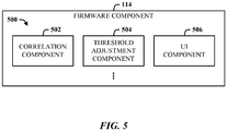
- FIG. 5 illustrates one or more algorithms 500 that can be provided in the firmware component 114 in support of clutch-height adjustment.
- the firmware component 114 can include a correlation component 502 that provide correlation processing such as autocorrelation and/or cross-correlation of image sensor light as the device is moved toward the clutch height.
- a threshold adjustment component 504 facilitates the adjustment of the clutch-height threshold and related parameters, such as correlation parameters for the correlation component 502.
- a user interface (UI) component 506 includes software such as an API that exposes firmware data and instructions, for example, to a UI via which the user can interact to manipulate settings and parameters.
- the image sensor when the device is in contact with the tracking surface an image is captured onto the image sensor.
- illumination can be captured by the image sensor such as contrast that is related to the tracking surface.
- the image of the reflected light source on the image sensor forms an illumination dome (a brighter spot toward the center of the image sensor that rolls in contrast to the sensor edges).
- the image on the image sensor also moves, although the dome remains somewhat static. In other words, the image may be on one side of the sensor, moves into the dome area and then away from the dome area towards the darker corner of the image sensor.
- the correlation component 502 includes one or more algorithms that process the relative contrast within a block of the image section by section and correlate the relative contrast rather than to the actual absolute intensity.
- the algorithm(s) are able to follow and notice the motion of that same texture as the texture moves across the image sensor.
- the contrast can vary in direct relationship to the tracking surface. This further indicates that the clutch height can be different for correspondingly different tracking surfaces. For example, on a very "strong" tracking surface, with high image contrast such as with a typical office desktop, there can be sufficient contrast that the clutch height can be set to be much higher than for a "weak” surface, such as paper, that does not provide much contrast. It is well understood that customer surfaces on which the device will be used, vary widely. Thus, manufacturers design devices using fixed settings that accommodate most surfaces such that the customers will have a positive experience when using the device.
- the firmware component 114 includes an adjustment "knob” that allows the power user to dictate how much autocorrelation to use by "dialing" down the clutch-height threshold. In other words, this can be adjusted based on the tracking surface and the particular application the customer is using.
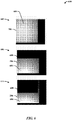
- FIG. 6 illustrates a set of image sensor views 600 of the illumination spot as the device (e.g., a mouse) is lifted off a mirror surface.
- An initial tracking view 602 shows the image sensor 206 and an illumination dome 604 (generally indicated by the circle) substantially centered in the sensor field.
- the z-axis height is, or approximately is, zero.
- the degree of tracking depends upon the surface contrast, and is particularly acute on faux-marble desks and dark surfaces.
- a shadow 608 caused by obfuscation component e.g., the aperture design, internal tabs, light cancellation/redirection techniques, etc.
- the amount (or size) of the shadow 608 can be set to ensure that the tracking mode is disabled. It may be the case that the second view 606 is not representative of the clutch height.
- the shadow 608 consumes even more of the sensor 206 as the illumination dome 604 continues to move off the sensor 206 causing the autocorrelation algorithm (and potentially other algorithms) to desire results indicating that he clutch-high threshold was reached.
- the disclosed architecture combines mechanics with algorithms to provide various clutch height adjustment over a range of possible surfaces and environments (e.g., gaming, general usage, etc.).
- the sensor is operated to take a series of pictures in time.
- the algorithm(s) correlate features from picture to picture.
- surface features that correspond to some surface height roughness are imaged.
- the imaged surface features have moved.
- the time difference between the two images can be measured to know the velocity and distance.
- the imaging occurs much faster than the vertical change in height of the device. Accordingly, in the second view 606, the image sensor captures the surface features and the shadow 608, which appear to not change at all relative to the image capture and correlation process. In other words, the device can no longer track because the image sensed picture at time T-1 and T-2 includes the black shadow pattern that is not moving.
- the dominant image content is the static shadow that does not move.
- the device stops tracking because it cannot distinguish between a small portion of the image content that is moving and the relatively larger black shadow that is not moving.
- the shadow begins to encroach more over the image sensor.
- the shadow formed from a straight edged occlusion in this example, moves over rows of pixels until the overall contrast triggers disabling of the tracking mode.
- aperture shapes can be employed in the opening of the bottom case, for example, of the mouse that strategically places a shadow feature. When the mouse is lifted the architecture of the geometry of the light changes so that the shadow then moves over the sensor so as to not affect the tracking.
- FIG. 7 illustrates one embodiment where a base of a mouse includes a "D-shaped" aperture where both incident and reflected rays transit for mouse tracking.
- the mouse sensor registers a shadow moving across the pixel array, as shown in FIG. 6 .
- the shadow makes a large number of pixels on the image sensor "dark", thereby effectively terminating mouse tracking.
- the algorithm(s) are overwhelmed by the black, non-moving, fixed-pattern noise that is present in the image stream and responsively terminate the tracking mode.
- the relatively fixed shadow causes a portion of the image to appear fixed (non-moving), and combined with the rest of the image being "softer" due to out-of-focus, the auto-correlation of the image is calculated as lower (softer) and tracking stops.
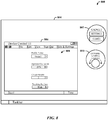
- FIG. 8 illustrates one or more software interfaces 800 for interacting with the navigational device algorithm(s) for parameter adjustments.
- a single-purpose application 802 also referred to as a gadget, widget, etc.
- a computer desktop 804 can be employed to read and present current settings and other device information, or receive the settings and the other device information.
- a device control UI 806 can be employed that facilitates user customization of one or more device settings 808.
- the user can create a Profile Name that intuitively describes the purpose for which the settings are to be used such as for a first gaming application (Game1) or a word processing application (e.g., WPapp1).
- Game1 a first gaming application
- WPapp1 a word processing application
- the profile name can then be reported to the gadget 802 for presentation to the current status of the device.
- control UI 806 can allow the user to set the aperture occlusion, where an adjustable aperture is provided.
- the adjustable aperture approach can use an electro-mechanically driven rotating set of differently sized blockers, such that the user can customize the clutch height by programming rotation of one of the blockers (or tabs) over a portion of the aperture. This can be controlled via the control UI 806 as an Aperture Occlusion setting, as a percentage, for example.
- the control UI 806 can also provide a Clutch Height setting, where each setting auto-configures the firmware algorithm(s) with parameters that auto-set the clutch height to the selected setting (e.g., more stringent height for gaming, less stringent height for word processing).
- the control UI 806 can also facilitate setting of the clutch height based on the Tracking Surface, with settings such as High for a highly reflective surface, for example.
- a gadget can be used to select a Profile Name, which selection then pushes the associated settings to the firmware component for configuring the correlation algorithm(s), etc., which can be done on-the-fly.
- the Control UI 806 can present a virtual knob that the user can turn to achieve the desired clutch height for a given application, or part of the application.
- the knob can also be presented as a Dynamic Gaming gadget 810, for example, that the user can manipulate during a computer game to fit the customized needs of the user. Manipulation automatically changes the clutch height settings to achieve the desired results.
- Another alternative example can include a combination of lenses that adjusts the depth of focus, rather than a specifically design aperture or adjustable aperture, for example.
- a narrow depth of focus will go out of focus quickly in response to off-surface activity of the device.
- clutch-height processing can be based on a second image sensor of the device, or an IR LED and IR receiver setup using the appropriate angles.
- an analog-to-digital (ADC) can be employed in combination with a photo transistor to dial-in where the light fall off, and use that setting as a baseline for clutch height.
- ADC analog-to-digital
- Another example can employ contact sensors (e.g. proximity) that sense when the device is off-surface, and how far off-surface.
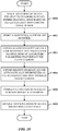
- FIG. 9 illustrates a method of managing clutch height of a navigational device.
- movement of a device relative to a tracking surface is tracked during a tracking mode based on reflected light impinging on an image sensor.
- a shadow is imposed on the image sensor that is automatically interpreted as a clutch height that disables the tracking mode.
- the shadow is imposed by occlusion (or obfuscation) of a portion the reflected light on the image sensor.
- One or more algorithms are then run (from firmware) to perform correlation operations on the images and the shadow.
- FIG. 10 illustrates a method of a method of managing clutch height using onboard algorithms.
- movement of the device relative to a tracking surface is tracked during a tracking mode based on reflected light impinging on an image sensor.
- one or more algorithms are stored as firmware on the device.
- algorithm settings are exposed via a user interface that facilitates manipulation of algorithm parameters that impact clutch height and that disable tracking mode.
- a shadow is imposed on the image sensor that is automatically interpreted as a clutch height that disables the tracking mode.
- changes in tracking surface images and the shadow are correlated (e.g., autocorrelated).
- tracking mode is disabled on the device when the correlation fails.
- FIG. 11 illustrates a method managing clutch height using an adjustable aperture.
- movement of the device relative to a tracking surface is tracked during a tracking mode based on reflected light impinging on an image sensor.
- a portion of the reflected light is occluded to create a shadow on the image sensor using an adjustable aperture in the base of the device.
- a set of blocking members is applied in association with the aperture each member having a different size.
- a blocking member is switched-in to adjust the clutch height based on the amount of blocking on the image sensor.
- FIG. 12 illustrates a navigation device 1200 that employs the clutch height embodiments disclosed herein.
- the device 1200 can include a light source assembly 1202, which can include light sources such as an LED or multiple LEDs.
- the light source assembly 1202 can also include optical elements such as lenses, collimators, and so on, utilized to achieve the desired tracking and switching modes.
- the device 1200 also includes a light detection assembly 1204 for detecting reflected light from the tracking surface for both tracking and switching functions.
- the light detection assembly 1204 can include an image sensor (e.g., CCD, CMOS) used for tracking.
- image sensor e.g., CCD, CMOS
- a switching assembly 1206 includes the logic for receiving a signal based on exceeding the clutch-height threshold and falling under the threshold, and switching between the various modes in accordance with the state of that signal. For example, if the state of the signal is logic high, this can correspond to exceeding the clutch-height threshold, indicating that the device 1200 tracking mode is to be disabled.
- the device 1200 can also include a power source 1208 such as batteries and/or a power converter for using line power.
- a wireless transceiver subsystem 1210 facilitates wireless communications (e.g., Bluetooth) such as in a mouse mode, for example.
- Program logic 1212 provides the operating software for the device 1200 for interfacing to a computer system, for example, or other systems, onboard control of the device functions and, for processing image correlation, tracking, and tracking mode management.
- external indicators 1214 can be provided to give feedback to the user for such functions as power, mode operation, and so on.
- a wheel 1216 can be provided for scrolling and other navigation operations normally associated with a wheel mouse.
- Device buttons 1218 facilitate operating the device 1200 (e.g., as a mouse). These can be programmable functions for the buttons.
- a component can be, but is not limited to being, a process running on a processor, a processor, a hard disk drive, multiple storage drives (of optical and/or magnetic storage medium), an object, an executable, a thread of execution, a program, and/or a computer.
- an application running on a server and the server can be a component.
- One or more components can reside within a process and/or thread of execution, and a component can be localized on one computer and/or distributed between two or more computers.
- the word "exemplary” may be used herein to mean serving as an example, instance, or illustration. Any aspect or design described herein as "exemplary” is not necessarily to be construed as preferred or advantageous over other aspects or designs.
- FIG. 13 there is illustrated a block diagram of a computing system 1300 operable to interface to a device having an adjustable clutch height in accordance with the disclosed architecture.
- FIG. 13 and the following discussion are intended to provide a brief, general description of the suitable computing system 1300 in which the various aspects can be implemented. While the description above is in the general context of computer-executable instructions that can run on one or more computers, those skilled in the art will recognize that a novel embodiment also can be implemented in combination with other program modules and/or as a combination of hardware and software.
- the computing system 1300 for implementing various aspects includes the computer 1302 having processing unit(s) 1304, a system memory 1306, and a system bus 1308.
- the processing unit(s) 1304 can be any of various commercially available processors such as single-processor, multi-processor, single-core units and multi-core units.
- processors such as single-processor, multi-processor, single-core units and multi-core units.
- those skilled in the art will appreciate that the novel methods can be practiced with other computer system configurations, including minicomputers, mainframe computers, as well as personal computers (e.g., desktop, laptop, etc.), hand-held computing devices, microprocessor-based or programmable consumer electronics, and the like, each of which can be operatively coupled to one or more associated devices.
- the system memory 1306 can include volatile (VOL) memory 1310 (e.g., random access memory (RAM)) and non-volatile memory (NON-VOL) 1312 (e.g., ROM, EPROM, EEPROM, etc.).
- VOL volatile
- NON-VOL non-volatile memory
- a basic input/output system (BIOS) can be stored in the non-volatile memory 1312, and includes the basic routines that facilitate the communication of data and signals between components within the computer 1302, such as during startup.
- the volatile memory 1310 can also include a high-speed RAM such as static RAM for caching data.
- the system bus 1308 provides an interface for system components including, but not limited to, the memory subsystem 1306 to the processing unit(s) 1304.
- the system bus 1308 can be any of several types of bus structure that can further interconnect to a memory bus (with or without a memory controller), and a peripheral bus (e.g., PCI, PCIe, AGP, LPC, etc.), using any of a variety of commercially available bus architectures.
- the computer 1302 further includes storage subsystem(s) 1314 and storage interface(s) 1316 for interfacing the storage subsystem(s) 1314 to the system bus 1308 and other desired computer components.
- the storage subsystem(s) 1314 can include one or more of a hard disk drive (HDD), a magnetic floppy disk drive (FDD), and/or optical disk storage drive (e.g., a CD-ROM drive DVD drive), for example.
- the storage interface(s) 1316 can include interface technologies such as EIDE, ATA, SATA, and IEEE 1394, for example.
- One or more programs and data can be stored in the memory subsystem 1306, a removable memory subsystem 1318 (e.g., flash drive form factor technology), and/or the storage subsystem(s) 1314, including an operating system 1320, one or more application programs 1322, other program modules 1324, and program data 1326.
- programs include routines, methods, data structures, other software components, etc., that perform particular tasks or implement particular abstract data types. All or portions of the operating system 1320, applications 1322, modules 1324, and/or data 1326 can also be cached in memory such as the volatile memory 1310, for example. It is to be appreciated that the disclosed architecture can be implemented with various commercially available operating systems or combinations of operating systems (e.g., as virtual machines).
- the storage subsystem(s) 1314 and memory subsystems (1306 and 1318) serve as computer readable media for volatile and non-volatile storage of data, data structures, computer-executable instructions, and so forth.
- Computer readable media can be any available media that can be accessed by the computer 1302 and includes volatile and non-volatile media, removable and non-removable media. For the computer 1302, the media accommodate the storage of data in any suitable digital format. It should be appreciated by those skilled in the art that other types of computer readable media can be employed such as zip drives, magnetic tape, flash memory cards, cartridges, and the like, for storing computer executable instructions for performing the novel methods of the disclosed architecture.
- a user can interact with the computer 1302, programs, and data using external user input devices 1328 such as a keyboard and a mouse.
- Other external user input devices 1328 can include a microphone, an IR (infrared) remote control, a joystick, a game pad, camera recognition systems, a stylus pen, touch screen, gesture systems (e.g., eye movement, head movement, etc.), and/or the like.
- the user can interact with the computer 1302, programs, and data using onboard user input devices 1330 such a touchpad, microphone, keyboard, etc., where the computer 1302 is a portable computer, for example.
- I/O device interface(s) 1332 are connected to the processing unit(s) 1304 through input/output (I/O) device interface(s) 1332 via the system bus 1308, but can be connected by other interfaces such as a parallel port, IEEE 1394 serial port, a game port, a USB port, an IR interface, etc.
- the I/O device interface(s) 1332 also facilitate the use of output peripherals 1334 such as printers, audio devices, camera devices, and so on, such as a sound card and/or onboard audio processing capability.
- One or more graphics interface(s) 1336 (also commonly referred to as a graphics processing unit (GPU)) provide graphics and video signals between the computer 1302 and external display(s) 1338 (e.g., LCD, plasma) and/or onboard displays 1340 (e.g., for portable computer).
- graphics interface(s) 1336 can also be manufactured as part of the computer system board.
- the computer 1302 can operate in a networked environment (e.g., IP) using logical connections via a wire/wireless communications subsystem 1342 to one or more networks and/or other computers.
- the other computers can include workstations, servers, routers, personal computers, microprocessor-based entertainment appliance, a peer device or other common network node, and typically include many or all of the elements described relative to the computer 1302.
- the logical connections can include wire/wireless connectivity to a local area network (LAN), a wide area network (WAN), hotspot, and so on.
- LAN and WAN networking environments are commonplace in offices and companies and facilitate enterprise-wide computer networks, such as intranets, all of which may connect to a global communications network such as the Internet.
- the computer 1302 When used in a networking environment the computer 1302 connects to the network via a wire/wireless communication subsystem 1342 (e.g., a network interface adapter, onboard transceiver subsystem, etc.) to communicate with wire/wireless networks, wire/wireless printers, wire/wireless input devices 1344, and so on.
- the computer 1302 can include a modem or has other means for establishing communications over the network.
- programs and data relative to the computer 1302 can be stored in the remote memory/storage device, as is associated with a distributed system. It will be appreciated that the network connections shown are exemplary and other means of establishing a communications link between the computers can be used.
- the computer 1302 is operable to communicate with wire/wireless devices or entities using the radio technologies such as the IEEE 802.xx family of standards, such as wireless devices operatively disposed in wireless communication (e.g., IEEE 802.11 over-the-air modulation techniques) with, for example, a printer, scanner, desktop and/or portable computer, personal digital assistant (PDA), communications satellite, any piece of equipment or location associated with a wirelessly detectable tag (e.g., a kiosk, news stand, restroom), and telephone.
- PDA personal digital assistant
- the communications can be a predefined structure as with a conventional network or simply an ad hoc communication between at least two devices.
- Wi-Fi networks use radio technologies called IEEE 802.11x (a, b, g, etc.) to provide secure, reliable, fast wireless connectivity.
- IEEE 802.11x a, b, g, etc.
- a Wi-Fi network can be used to connect computers to each other, to the Internet, and to wire networks (which use IEEE 802.3-related media and functions).
Landscapes
- Engineering & Computer Science (AREA)
- General Engineering & Computer Science (AREA)
- Theoretical Computer Science (AREA)
- Human Computer Interaction (AREA)
- Physics & Mathematics (AREA)
- General Physics & Mathematics (AREA)
- Position Input By Displaying (AREA)
- Length Measuring Devices By Optical Means (AREA)
Claims (9)
- Kopplungshöhenverwaltungssystem (100), umfassend:eine Lichtquellenanordnung (102) zum Emittieren von einfallenden Licht auf eine Verfolgungsoberfläche und eine Lichterfassungsanordnung zum Aufnehmen von Licht von der Verfolgungsoberfläche zum Verfolgen einer Bewegung einer Vorrichtung relativ zu der Verfolgungsoberfläche; undeine Verdunkelungskomponente (112) zum Reduzieren einer Menge des Lichts, das von der Lichterfassungsanordnung erfasst wird, in Reaktion auf die Entkopplung der Vorrichtung von der Verfolgungsoberfläche,wobei die Verdunklungskomponente eine Öffnung beinhaltet, durch die das einfallende Licht auf die Verfolgungsoberfläche fällt und durch die das von der Verfolgungsoberfläche reflektierte Licht aufgenommen wird, wobei die Öffnung mechanisch dazu konfiguriert ist, das zu der Erfassungsanordnung reflektierte Licht zu verdunkeln,wobei die Öffnung dazu einstellbar ist, die Verdunklung des reflektierten Lichts auf einem Bildsensor der Lichterfassungsanordnung zu verändern, undwobei die einstellbare Öffnung einem Satz aus Blockierungselementen zugehörig ist, die jeweils eine unterschiedliche Blockierungsgröße aufweisen, so dass, wenn sie in die Öffnung geschaltet werden, das reflektierte Licht in entsprechend unterschiedlichen Mengen teilweise verdunkelt wird, wenn die Vorrichtung von der Verfolgungsoberfläche abgehoben wird.
- System nach Anspruch 1, wobei die Verdunklungskomponente in einem Pfad des einfallenden Lichts platziert wird, um eine Menge des einfallenden Lichts zu reduzieren, das die Verfolgungsoberfläche erreicht, in Reaktion auf die Entkopplung der Vorrichtung.
- System nach Anspruch 1, wobei die Öffnung eine Kante beinhaltet, die das reflektierte Licht auf einem Bildsensor der Lichterfassungsanordnung zunehmend verdunkelt, wenn die Distanz zu der Verfolgungsoberfläche zunimmt.
- System nach Anspruch 1, wobei die Verdunklungskomponente das reflektierte Licht zunehmend verdunkelt, wenn die Distanz zu der Verfolgungsoberfläche zunimmt, und die Lichterfassungsanordnung einen Verfolgungsmodus deaktiviert, wenn die Distanz einen Kopplungshöhenschwellenwert erreicht.
- System nach Anspruch 1, des Weiteren umfassend Firmware zum Anpassen eines Korrelationsparameters, der zum Berechnen eines Kopplungshöhenschwellenwerts verwendet wird, und die Kopplungshöhenparameter anzeigt, die über eine Softwareschnittstelle individualisiert werden können.
- Verfahren zum Verwalten der Kopplungshöhe, umfassend:Verfolgen der Bewegung einer Vorrichtung, die eine Lichtquellenanordnung (102), eine Lichterfassungsanordnung (112) und eine Öffnung umfasst, relativ zu einer Verfolgungsoberfläche während eines Verfolgungsmodus basierend auf reflektiertem Licht, das auf einen Bildsensor (900) einfällt;Legen eines Schattens auf den Bildsensor, der automatisch als eine Kopplungshöhe interpretiert wird, welche den Verfolgungsmodus (902) deaktiviert; undVerdunkeln eines Teils des reflektierten Lichts, um den Schatten zu erzeugen, unter Verwendung einer einstellbaren Öffnung, die in einer Basis der Vorrichtung ausgebildet ist, durch die das einfallende Licht und das reflektierte Licht verlaufen, wobei die einstellbare Öffnung einem Satz aus Blockierungselementen zugehörig ist, die jeweils eine unterschiedliche Blockierungsgröße aufweisen, so dass, wenn sie in die Öffnung geschaltet werden, das reflektierte Licht in entsprechend unterschiedlichen Mengen teilweise verdunkelt wird, wenn die Vorrichtung von der Verdunklungsoberfläche abgehoben wird.
- Verfahren nach Anspruch 6, des Weiteren umfassend:Bestimmen einer Korrelation zwischen Änderungen in Verfolgungsoberflächenbildern und dem Schatten; und Deaktivieren des Verfolgungsmodus der Vorrichtung, wenn die Korrelation fehlschlägt.
- Verfahren nach Anspruch 6, des Weiteren umfassend das Anzeigen von Algorithmuseinstellungen der Vorrichtung über eine Benutzerschnittstelle, welche die Manipulation von Algorithmusparametern ermöglicht, welche sich auf die Kopplungshöhe auswirken.
- Verfahren nach Anspruch 6, des Weiteren umfassend das mechanische Anpassen der Vorrichtung, bei der es sich um eine optische Maus handelt, um die Verfolgung beizubehalten, wenn sie auf der Verfolgungsoberfläche erfolgt, und die Verfolgung zu deaktivieren, wenn sie sich um eine vorgegebene Distanz von der Verfolgungsoberfläche entfernt.
Applications Claiming Priority (2)
| Application Number | Priority Date | Filing Date | Title |
|---|---|---|---|
| US12/204,824 US8570194B2 (en) | 2008-09-05 | 2008-09-05 | Clutch-height adjustment in an optical tracking device |
| PCT/US2009/055951 WO2010028191A2 (en) | 2008-09-05 | 2009-09-03 | Clutch-height adjustment in an optical tracking device |
Publications (3)
| Publication Number | Publication Date |
|---|---|
| EP2321715A2 EP2321715A2 (de) | 2011-05-18 |
| EP2321715A4 EP2321715A4 (de) | 2014-04-02 |
| EP2321715B1 true EP2321715B1 (de) | 2018-04-25 |
Family
ID=41797867
Family Applications (1)
| Application Number | Title | Priority Date | Filing Date |
|---|---|---|---|
| EP09812247.6A Active EP2321715B1 (de) | 2008-09-05 | 2009-09-03 | Kupplungshöheneinstellung in einer vorrichtung für optische verfolgung |
Country Status (5)
| Country | Link |
|---|---|
| US (2) | US8570194B2 (de) |
| EP (1) | EP2321715B1 (de) |
| JP (1) | JP2012502278A (de) |
| CN (1) | CN102144204B (de) |
| WO (1) | WO2010028191A2 (de) |
Families Citing this family (8)
| Publication number | Priority date | Publication date | Assignee | Title |
|---|---|---|---|---|
| US8570194B2 (en) | 2008-09-05 | 2013-10-29 | Microsoft Corporation | Clutch-height adjustment in an optical tracking device |
| TWI471521B (zh) * | 2010-07-23 | 2015-02-01 | Pixart Imaging Inc | 位移估測方法及使用該方法之位移偵測裝置 |
| CN102890570A (zh) * | 2011-07-20 | 2013-01-23 | 致伸科技股份有限公司 | 可改变外型的鼠标 |
| DE102014203645B4 (de) * | 2014-02-28 | 2016-06-02 | Trumpf Werkzeugmaschinen Gmbh + Co. Kg | Verfahren und Vorrichtung zum optischen Bestimmen eines Abstandes |
| AU2016423733B2 (en) * | 2016-09-23 | 2022-05-26 | Razer (Asia-Pacific) Pte. Ltd. | Input devices, methods for providing an input to a computing system and computer readable media |
| US11409375B2 (en) * | 2016-11-11 | 2022-08-09 | Pixart Imaging Inc. | Method and apparatus for adjusting optical setting of optical input device and related optical input device |
| US11480664B2 (en) * | 2019-06-05 | 2022-10-25 | Pixart Imaging Inc. | Optical detection device of detecting a distance relative to a target object |
| US11029765B1 (en) * | 2020-06-03 | 2021-06-08 | Pixart Imaging Inc. | Lift detection method for mouse and apparatus thereof |
Family Cites Families (27)
| Publication number | Priority date | Publication date | Assignee | Title |
|---|---|---|---|---|
| US6950094B2 (en) * | 1998-03-30 | 2005-09-27 | Agilent Technologies, Inc | Seeing eye mouse for a computer system |
| US7071922B2 (en) * | 2002-11-15 | 2006-07-04 | Edison Opto Corp. | Optical mouse with rolling ball |
| US7263242B2 (en) * | 2003-01-23 | 2007-08-28 | Avago Technologies Ecbu Ip (Singapore) Pte. Ltd. | Method for detecting repetitive surfaces in an optical mouse |
| US7227531B2 (en) * | 2003-08-15 | 2007-06-05 | Microsoft Corporation | Data input device for tracking and detecting lift-off from a tracking surface by a reflected laser speckle pattern |
| US7161582B2 (en) * | 2003-08-29 | 2007-01-09 | Microsoft Corporation | Data input device for tracking and detecting lift-off from a tracking surface by a reflected laser speckle pattern |
| US7324086B2 (en) * | 2004-01-21 | 2008-01-29 | Microsoft Corporation | Data input device and method for detecting lift-off from a tracking surface by laser doppler self-mixing effects |
| US20050156874A1 (en) * | 2004-01-21 | 2005-07-21 | Microsoft Corporation | Data input device and method for detecting life-off from a tracking surface by laser doppler self-mixing effects |
| US7221356B2 (en) * | 2004-02-26 | 2007-05-22 | Microsoft Corporation | Data input device and method for detecting an off-surface condition by a laser speckle size characteristic |
| WO2005088435A1 (en) | 2004-03-11 | 2005-09-22 | Mobisol Inc. | Pointing device with an integrated optical structure |
| KR100648964B1 (ko) * | 2004-03-11 | 2006-11-27 | (주)모비솔 | 격자 또는 인식 가능한 패턴 이동의 감지를 이용한 2차원포인팅 장치 |
| US7339575B2 (en) | 2004-05-25 | 2008-03-04 | Avago Technologies Ecbu Ip Pte Ltd | Optical pointing device with variable focus |
| US7557799B2 (en) * | 2004-06-17 | 2009-07-07 | Avago Technologies Ecbu Ip (Singapore) Pte. Ltd. | System for determining pointer position, movement, and angle |
| KR100620951B1 (ko) * | 2004-10-06 | 2006-09-19 | 주식회사 애트랩 | 광차단부를 구비한 광마우스 |
| US7189985B2 (en) * | 2004-10-30 | 2007-03-13 | Avago Technologies General Ip (Singapore) Pte. Ltd. | Tracking separation between an object and a surface using a reducing structure |
| US7405727B2 (en) * | 2004-12-15 | 2008-07-29 | Em Microelectronic-Marin Sa | Lift detection mechanism for optical mouse sensor |
| US7388283B2 (en) | 2005-02-04 | 2008-06-17 | Avago Technologies Ecbu Ip Pte Ltd | Method and device for integrating an illumination source and detector into the same IC package that allows angular illumination with a common planar leadframe |
| US20060209027A1 (en) * | 2005-03-21 | 2006-09-21 | Pixart Imaging, Inc. | Optical mouse with a light-interfering unit |
| KR101108438B1 (ko) | 2005-06-29 | 2012-02-08 | 레이저 유에스에이 리미티드 | 광학센서에 있어서 시계심도 조절방법 및 시스템 |
| US7898524B2 (en) * | 2005-06-30 | 2011-03-01 | Logitech Europe S.A. | Optical displacement detection over varied surfaces |
| JP2007129403A (ja) | 2005-11-02 | 2007-05-24 | Olympus Corp | 画像符号化装置および画像処理システム |
| US8013841B2 (en) * | 2006-06-16 | 2011-09-06 | Em Microelectronic-Marin S.A. | Enhanced lift detection technique for a laser illuminated optical mouse sensor |
| US7755604B2 (en) * | 2006-06-19 | 2010-07-13 | Cypress Semiconductor Corporation | Optical navigation sensor with tracking and lift detection for optically transparent contact surfaces |
| US7777722B2 (en) * | 2006-06-23 | 2010-08-17 | Microsoft Corporation | Multi-mode optical navigation |
| US7868281B2 (en) * | 2006-11-20 | 2011-01-11 | Avago Technologies Ecbu Ip (Singapore) Pte. Ltd. | Optical navigation system and method of estimating motion with optical lift detection |
| US8000736B2 (en) * | 2007-01-06 | 2011-08-16 | Apple Inc. | User programmable switch for portable data processing devices |
| DE202007005468U1 (de) * | 2007-04-16 | 2007-07-12 | Wu, Cheng-Cheng, Chung Ho City | Struktur eines optischen Systems für eine Lasermaus |
| US8570194B2 (en) | 2008-09-05 | 2013-10-29 | Microsoft Corporation | Clutch-height adjustment in an optical tracking device |
-
2008
- 2008-09-05 US US12/204,824 patent/US8570194B2/en not_active Expired - Fee Related
-
2009
- 2009-09-03 JP JP2011526212A patent/JP2012502278A/ja not_active Withdrawn
- 2009-09-03 CN CN200980135830.2A patent/CN102144204B/zh not_active Expired - Fee Related
- 2009-09-03 EP EP09812247.6A patent/EP2321715B1/de active Active
- 2009-09-03 WO PCT/US2009/055951 patent/WO2010028191A2/en not_active Ceased
-
2013
- 2013-10-28 US US14/064,796 patent/US10048780B2/en active Active
Non-Patent Citations (1)
| Title |
|---|
| None * |
Also Published As
| Publication number | Publication date |
|---|---|
| US20140049471A1 (en) | 2014-02-20 |
| US20100060488A1 (en) | 2010-03-11 |
| CN102144204B (zh) | 2015-04-29 |
| EP2321715A2 (de) | 2011-05-18 |
| WO2010028191A3 (en) | 2010-06-03 |
| US10048780B2 (en) | 2018-08-14 |
| CN102144204A (zh) | 2011-08-03 |
| EP2321715A4 (de) | 2014-04-02 |
| WO2010028191A2 (en) | 2010-03-11 |
| JP2012502278A (ja) | 2012-01-26 |
| US8570194B2 (en) | 2013-10-29 |
Similar Documents
| Publication | Publication Date | Title |
|---|---|---|
| US10048780B2 (en) | Adjustment of an optical tracking device | |
| US11917126B2 (en) | Systems and methods for eye tracking in virtual reality and augmented reality applications | |
| US10139929B2 (en) | Information handling system interactive totems | |
| US11106314B2 (en) | Continuous calibration of an information handling system projected user interface | |
| US7969426B2 (en) | Light sensitive display interface for computing devices | |
| US9983717B2 (en) | Disambiguation of false touch inputs at an information handling system projected user interface | |
| US10558279B2 (en) | Dual mode optical navigation device | |
| US9720446B2 (en) | Information handling system projected work space calibration | |
| EP3614239B1 (de) | Steuerung einer elektronischen vorrichtung als reaktion auf die fingerrotation auf einem fingerabdrucksensor und entsprechende verfahren | |
| US9921644B2 (en) | Information handling system non-linear user interface | |
| US20160313822A1 (en) | Context Based Peripheral Management for Interacting with an Information Handling System | |
| JP2017142726A (ja) | 電子黒板システム、表示装置及び表示方法 | |
| KR20070011396A (ko) | 광 입력 및/또는 제어 디바이스 | |
| US9720550B2 (en) | Adaptable input active zones at an information handling system projected user interface | |
| US20210333873A1 (en) | Electronic apparatus, method for controlling the same, and storage medium | |
| CN107111354B (zh) | 非故意触摸拒绝 | |
| US11520400B2 (en) | Electronic apparatus and method for controlling the same | |
| US20080136781A1 (en) | Dual light sources mouse capable of controlling the on and off state of the second light source |
Legal Events
| Date | Code | Title | Description |
|---|---|---|---|
| PUAI | Public reference made under article 153(3) epc to a published international application that has entered the european phase |
Free format text: ORIGINAL CODE: 0009012 |
|
| 17P | Request for examination filed |
Effective date: 20110215 |
|
| AK | Designated contracting states |
Kind code of ref document: A2 Designated state(s): AT BE BG CH CY CZ DE DK EE ES FI FR GB GR HR HU IE IS IT LI LT LU LV MC MK MT NL NO PL PT RO SE SI SK SM TR |
|
| AX | Request for extension of the european patent |
Extension state: AL BA RS |
|
| DAX | Request for extension of the european patent (deleted) | ||
| REG | Reference to a national code |
Ref country code: DE Ref legal event code: R079 Ref document number: 602009052006 Country of ref document: DE Free format text: PREVIOUS MAIN CLASS: G06F0003033000 Ipc: G06F0003030000 |
|
| RIN1 | Information on inventor provided before grant (corrected) |
Inventor name: HASTINGS, BRIAN, L. Inventor name: DEPUE, MARSHALL, T. Inventor name: BOHN, DAVID, D. Inventor name: KLEIN, STEPHEN, C. Inventor name: LANE, DAVID, M. |
|
| A4 | Supplementary search report drawn up and despatched |
Effective date: 20140305 |
|
| RIC1 | Information provided on ipc code assigned before grant |
Ipc: G06F 3/033 20130101ALI20140227BHEP Ipc: G06F 3/0354 20130101ALI20140227BHEP Ipc: G06F 3/03 20060101AFI20140227BHEP Ipc: G06F 3/038 20130101ALI20140227BHEP |
|
| RAP1 | Party data changed (applicant data changed or rights of an application transferred) |
Owner name: MICROSOFT TECHNOLOGY LICENSING, LLC |
|
| 17Q | First examination report despatched |
Effective date: 20170713 |
|
| GRAP | Despatch of communication of intention to grant a patent |
Free format text: ORIGINAL CODE: EPIDOSNIGR1 |
|
| INTG | Intention to grant announced |
Effective date: 20171129 |
|
| GRAA | (expected) grant |
Free format text: ORIGINAL CODE: 0009210 |
|
| GRAS | Grant fee paid |
Free format text: ORIGINAL CODE: EPIDOSNIGR3 |
|
| AK | Designated contracting states |
Kind code of ref document: B1 Designated state(s): AT BE BG CH CY CZ DE DK EE ES FI FR GB GR HR HU IE IS IT LI LT LU LV MC MK MT NL NO PL PT RO SE SI SK SM TR |
|
| REG | Reference to a national code |
Ref country code: GB Ref legal event code: FG4D |
|
| REG | Reference to a national code |
Ref country code: CH Ref legal event code: EP |
|
| REG | Reference to a national code |
Ref country code: AT Ref legal event code: REF Ref document number: 993579 Country of ref document: AT Kind code of ref document: T Effective date: 20180515 |
|
| REG | Reference to a national code |
Ref country code: IE Ref legal event code: FG4D |
|
| REG | Reference to a national code |
Ref country code: DE Ref legal event code: R096 Ref document number: 602009052006 Country of ref document: DE |
|
| REG | Reference to a national code |
Ref country code: NL Ref legal event code: FP |
|
| REG | Reference to a national code |
Ref country code: FR Ref legal event code: PLFP Year of fee payment: 10 |
|
| REG | Reference to a national code |
Ref country code: LT Ref legal event code: MG4D |
|
| PG25 | Lapsed in a contracting state [announced via postgrant information from national office to epo] |
Ref country code: BG Free format text: LAPSE BECAUSE OF FAILURE TO SUBMIT A TRANSLATION OF THE DESCRIPTION OR TO PAY THE FEE WITHIN THE PRESCRIBED TIME-LIMIT Effective date: 20180725 Ref country code: NO Free format text: LAPSE BECAUSE OF FAILURE TO SUBMIT A TRANSLATION OF THE DESCRIPTION OR TO PAY THE FEE WITHIN THE PRESCRIBED TIME-LIMIT Effective date: 20180725 Ref country code: PL Free format text: LAPSE BECAUSE OF FAILURE TO SUBMIT A TRANSLATION OF THE DESCRIPTION OR TO PAY THE FEE WITHIN THE PRESCRIBED TIME-LIMIT Effective date: 20180425 Ref country code: LT Free format text: LAPSE BECAUSE OF FAILURE TO SUBMIT A TRANSLATION OF THE DESCRIPTION OR TO PAY THE FEE WITHIN THE PRESCRIBED TIME-LIMIT Effective date: 20180425 Ref country code: ES Free format text: LAPSE BECAUSE OF FAILURE TO SUBMIT A TRANSLATION OF THE DESCRIPTION OR TO PAY THE FEE WITHIN THE PRESCRIBED TIME-LIMIT Effective date: 20180425 Ref country code: SE Free format text: LAPSE BECAUSE OF FAILURE TO SUBMIT A TRANSLATION OF THE DESCRIPTION OR TO PAY THE FEE WITHIN THE PRESCRIBED TIME-LIMIT Effective date: 20180425 Ref country code: FI Free format text: LAPSE BECAUSE OF FAILURE TO SUBMIT A TRANSLATION OF THE DESCRIPTION OR TO PAY THE FEE WITHIN THE PRESCRIBED TIME-LIMIT Effective date: 20180425 |
|
| PG25 | Lapsed in a contracting state [announced via postgrant information from national office to epo] |
Ref country code: LV Free format text: LAPSE BECAUSE OF FAILURE TO SUBMIT A TRANSLATION OF THE DESCRIPTION OR TO PAY THE FEE WITHIN THE PRESCRIBED TIME-LIMIT Effective date: 20180425 Ref country code: GR Free format text: LAPSE BECAUSE OF FAILURE TO SUBMIT A TRANSLATION OF THE DESCRIPTION OR TO PAY THE FEE WITHIN THE PRESCRIBED TIME-LIMIT Effective date: 20180726 Ref country code: HR Free format text: LAPSE BECAUSE OF FAILURE TO SUBMIT A TRANSLATION OF THE DESCRIPTION OR TO PAY THE FEE WITHIN THE PRESCRIBED TIME-LIMIT Effective date: 20180425 |
|
| REG | Reference to a national code |
Ref country code: AT Ref legal event code: MK05 Ref document number: 993579 Country of ref document: AT Kind code of ref document: T Effective date: 20180425 |
|
| PG25 | Lapsed in a contracting state [announced via postgrant information from national office to epo] |
Ref country code: PT Free format text: LAPSE BECAUSE OF FAILURE TO SUBMIT A TRANSLATION OF THE DESCRIPTION OR TO PAY THE FEE WITHIN THE PRESCRIBED TIME-LIMIT Effective date: 20180827 |
|
| REG | Reference to a national code |
Ref country code: DE Ref legal event code: R097 Ref document number: 602009052006 Country of ref document: DE |
|
| PG25 | Lapsed in a contracting state [announced via postgrant information from national office to epo] |
Ref country code: EE Free format text: LAPSE BECAUSE OF FAILURE TO SUBMIT A TRANSLATION OF THE DESCRIPTION OR TO PAY THE FEE WITHIN THE PRESCRIBED TIME-LIMIT Effective date: 20180425 Ref country code: DK Free format text: LAPSE BECAUSE OF FAILURE TO SUBMIT A TRANSLATION OF THE DESCRIPTION OR TO PAY THE FEE WITHIN THE PRESCRIBED TIME-LIMIT Effective date: 20180425 Ref country code: SK Free format text: LAPSE BECAUSE OF FAILURE TO SUBMIT A TRANSLATION OF THE DESCRIPTION OR TO PAY THE FEE WITHIN THE PRESCRIBED TIME-LIMIT Effective date: 20180425 Ref country code: CZ Free format text: LAPSE BECAUSE OF FAILURE TO SUBMIT A TRANSLATION OF THE DESCRIPTION OR TO PAY THE FEE WITHIN THE PRESCRIBED TIME-LIMIT Effective date: 20180425 Ref country code: AT Free format text: LAPSE BECAUSE OF FAILURE TO SUBMIT A TRANSLATION OF THE DESCRIPTION OR TO PAY THE FEE WITHIN THE PRESCRIBED TIME-LIMIT Effective date: 20180425 Ref country code: RO Free format text: LAPSE BECAUSE OF FAILURE TO SUBMIT A TRANSLATION OF THE DESCRIPTION OR TO PAY THE FEE WITHIN THE PRESCRIBED TIME-LIMIT Effective date: 20180425 |
|
| PG25 | Lapsed in a contracting state [announced via postgrant information from national office to epo] |
Ref country code: SM Free format text: LAPSE BECAUSE OF FAILURE TO SUBMIT A TRANSLATION OF THE DESCRIPTION OR TO PAY THE FEE WITHIN THE PRESCRIBED TIME-LIMIT Effective date: 20180425 Ref country code: IT Free format text: LAPSE BECAUSE OF FAILURE TO SUBMIT A TRANSLATION OF THE DESCRIPTION OR TO PAY THE FEE WITHIN THE PRESCRIBED TIME-LIMIT Effective date: 20180425 |
|
| PLBE | No opposition filed within time limit |
Free format text: ORIGINAL CODE: 0009261 |
|
| STAA | Information on the status of an ep patent application or granted ep patent |
Free format text: STATUS: NO OPPOSITION FILED WITHIN TIME LIMIT |
|
| 26N | No opposition filed |
Effective date: 20190128 |
|
| PG25 | Lapsed in a contracting state [announced via postgrant information from national office to epo] |
Ref country code: MC Free format text: LAPSE BECAUSE OF FAILURE TO SUBMIT A TRANSLATION OF THE DESCRIPTION OR TO PAY THE FEE WITHIN THE PRESCRIBED TIME-LIMIT Effective date: 20180425 |
|
| REG | Reference to a national code |
Ref country code: CH Ref legal event code: PL |
|
| PG25 | Lapsed in a contracting state [announced via postgrant information from national office to epo] |
Ref country code: SI Free format text: LAPSE BECAUSE OF FAILURE TO SUBMIT A TRANSLATION OF THE DESCRIPTION OR TO PAY THE FEE WITHIN THE PRESCRIBED TIME-LIMIT Effective date: 20180425 |
|
| REG | Reference to a national code |
Ref country code: BE Ref legal event code: MM Effective date: 20180930 |
|
| REG | Reference to a national code |
Ref country code: IE Ref legal event code: MM4A |
|
| PG25 | Lapsed in a contracting state [announced via postgrant information from national office to epo] |
Ref country code: LU Free format text: LAPSE BECAUSE OF NON-PAYMENT OF DUE FEES Effective date: 20180903 |
|
| PG25 | Lapsed in a contracting state [announced via postgrant information from national office to epo] |
Ref country code: IE Free format text: LAPSE BECAUSE OF NON-PAYMENT OF DUE FEES Effective date: 20180903 |
|
| PG25 | Lapsed in a contracting state [announced via postgrant information from national office to epo] |
Ref country code: BE Free format text: LAPSE BECAUSE OF NON-PAYMENT OF DUE FEES Effective date: 20180930 Ref country code: LI Free format text: LAPSE BECAUSE OF NON-PAYMENT OF DUE FEES Effective date: 20180930 Ref country code: CH Free format text: LAPSE BECAUSE OF NON-PAYMENT OF DUE FEES Effective date: 20180930 |
|
| PG25 | Lapsed in a contracting state [announced via postgrant information from national office to epo] |
Ref country code: MT Free format text: LAPSE BECAUSE OF NON-PAYMENT OF DUE FEES Effective date: 20180903 |
|
| PG25 | Lapsed in a contracting state [announced via postgrant information from national office to epo] |
Ref country code: TR Free format text: LAPSE BECAUSE OF FAILURE TO SUBMIT A TRANSLATION OF THE DESCRIPTION OR TO PAY THE FEE WITHIN THE PRESCRIBED TIME-LIMIT Effective date: 20180425 |
|
| PG25 | Lapsed in a contracting state [announced via postgrant information from national office to epo] |
Ref country code: HU Free format text: LAPSE BECAUSE OF FAILURE TO SUBMIT A TRANSLATION OF THE DESCRIPTION OR TO PAY THE FEE WITHIN THE PRESCRIBED TIME-LIMIT; INVALID AB INITIO Effective date: 20090903 |
|
| PG25 | Lapsed in a contracting state [announced via postgrant information from national office to epo] |
Ref country code: MK Free format text: LAPSE BECAUSE OF NON-PAYMENT OF DUE FEES Effective date: 20180425 Ref country code: CY Free format text: LAPSE BECAUSE OF FAILURE TO SUBMIT A TRANSLATION OF THE DESCRIPTION OR TO PAY THE FEE WITHIN THE PRESCRIBED TIME-LIMIT Effective date: 20180425 |
|
| PG25 | Lapsed in a contracting state [announced via postgrant information from national office to epo] |
Ref country code: IS Free format text: LAPSE BECAUSE OF FAILURE TO SUBMIT A TRANSLATION OF THE DESCRIPTION OR TO PAY THE FEE WITHIN THE PRESCRIBED TIME-LIMIT Effective date: 20180825 |
|
| P01 | Opt-out of the competence of the unified patent court (upc) registered |
Effective date: 20230505 |
|
| PGFP | Annual fee paid to national office [announced via postgrant information from national office to epo] |
Ref country code: NL Payment date: 20230822 Year of fee payment: 15 |
|
| PGFP | Annual fee paid to national office [announced via postgrant information from national office to epo] |
Ref country code: DE Payment date: 20230822 Year of fee payment: 15 |
|
| REG | Reference to a national code |
Ref country code: DE Ref legal event code: R119 Ref document number: 602009052006 Country of ref document: DE |
|
| REG | Reference to a national code |
Ref country code: NL Ref legal event code: MM Effective date: 20241001 |
|
| PG25 | Lapsed in a contracting state [announced via postgrant information from national office to epo] |
Ref country code: NL Free format text: LAPSE BECAUSE OF NON-PAYMENT OF DUE FEES Effective date: 20241001 |
|
| PG25 | Lapsed in a contracting state [announced via postgrant information from national office to epo] |
Ref country code: DE Free format text: LAPSE BECAUSE OF NON-PAYMENT OF DUE FEES Effective date: 20250401 |
|
| PGFP | Annual fee paid to national office [announced via postgrant information from national office to epo] |
Ref country code: GB Payment date: 20250822 Year of fee payment: 17 |
|
| PGFP | Annual fee paid to national office [announced via postgrant information from national office to epo] |
Ref country code: FR Payment date: 20250821 Year of fee payment: 17 |