EP2321493B1 - Actionnement a distance d'outils de forage de puits - Google Patents
Actionnement a distance d'outils de forage de puits Download PDFInfo
- Publication number
- EP2321493B1 EP2321493B1 EP08799341.6A EP08799341A EP2321493B1 EP 2321493 B1 EP2321493 B1 EP 2321493B1 EP 08799341 A EP08799341 A EP 08799341A EP 2321493 B1 EP2321493 B1 EP 2321493B1
- Authority
- EP
- European Patent Office
- Prior art keywords
- conductors
- well
- actuation
- well tool
- tools
- Prior art date
- Legal status (The legal status is an assumption and is not a legal conclusion. Google has not performed a legal analysis and makes no representation as to the accuracy of the status listed.)
- Not-in-force
Links
- 239000004020 conductor Substances 0.000 claims description 200
- 239000012530 fluid Substances 0.000 claims description 35
- 238000000034 method Methods 0.000 claims description 35
- 238000004891 communication Methods 0.000 claims description 7
- 238000006073 displacement reaction Methods 0.000 claims description 4
- 238000010586 diagram Methods 0.000 description 9
- 230000008901 benefit Effects 0.000 description 7
- 238000004519 manufacturing process Methods 0.000 description 6
- 230000001276 controlling effect Effects 0.000 description 3
- 238000007792 addition Methods 0.000 description 1
- 238000012217 deletion Methods 0.000 description 1
- 230000037430 deletion Effects 0.000 description 1
- 230000001419 dependent effect Effects 0.000 description 1
- 230000000694 effects Effects 0.000 description 1
- 238000007667 floating Methods 0.000 description 1
- 230000000977 initiatory effect Effects 0.000 description 1
- 238000002347 injection Methods 0.000 description 1
- 239000007924 injection Substances 0.000 description 1
- 230000007246 mechanism Effects 0.000 description 1
- 239000002184 metal Substances 0.000 description 1
- 238000012986 modification Methods 0.000 description 1
- 230000004048 modification Effects 0.000 description 1
- 238000010248 power generation Methods 0.000 description 1
- 230000001105 regulatory effect Effects 0.000 description 1
- 238000007789 sealing Methods 0.000 description 1
- 239000000243 solution Substances 0.000 description 1
- 238000006467 substitution reaction Methods 0.000 description 1
Images


Classifications
-
- E—FIXED CONSTRUCTIONS
- E21—EARTH OR ROCK DRILLING; MINING
- E21B—EARTH OR ROCK DRILLING; OBTAINING OIL, GAS, WATER, SOLUBLE OR MELTABLE MATERIALS OR A SLURRY OF MINERALS FROM WELLS
- E21B23/00—Apparatus for displacing, setting, locking, releasing or removing tools, packers or the like in boreholes or wells
-
- E—FIXED CONSTRUCTIONS
- E21—EARTH OR ROCK DRILLING; MINING
- E21B—EARTH OR ROCK DRILLING; OBTAINING OIL, GAS, WATER, SOLUBLE OR MELTABLE MATERIALS OR A SLURRY OF MINERALS FROM WELLS
- E21B34/00—Valve arrangements for boreholes or wells
- E21B34/06—Valve arrangements for boreholes or wells in wells
- E21B34/066—Valve arrangements for boreholes or wells in wells electrically actuated
-
- E—FIXED CONSTRUCTIONS
- E21—EARTH OR ROCK DRILLING; MINING
- E21B—EARTH OR ROCK DRILLING; OBTAINING OIL, GAS, WATER, SOLUBLE OR MELTABLE MATERIALS OR A SLURRY OF MINERALS FROM WELLS
- E21B34/00—Valve arrangements for boreholes or wells
- E21B34/06—Valve arrangements for boreholes or wells in wells
- E21B34/10—Valve arrangements for boreholes or wells in wells operated by control fluid supplied from outside the borehole
-
- E—FIXED CONSTRUCTIONS
- E21—EARTH OR ROCK DRILLING; MINING
- E21B—EARTH OR ROCK DRILLING; OBTAINING OIL, GAS, WATER, SOLUBLE OR MELTABLE MATERIALS OR A SLURRY OF MINERALS FROM WELLS
- E21B41/00—Equipment or details not covered by groups E21B15/00 - E21B40/00
-
- E—FIXED CONSTRUCTIONS
- E21—EARTH OR ROCK DRILLING; MINING
- E21B—EARTH OR ROCK DRILLING; OBTAINING OIL, GAS, WATER, SOLUBLE OR MELTABLE MATERIALS OR A SLURRY OF MINERALS FROM WELLS
- E21B47/00—Survey of boreholes or wells
- E21B47/12—Means for transmitting measuring-signals or control signals from the well to the surface, or from the surface to the well, e.g. for logging while drilling
- E21B47/125—Means for transmitting measuring-signals or control signals from the well to the surface, or from the surface to the well, e.g. for logging while drilling using earth as an electrical conductor
Definitions
- the present disclosure relates generally to operations performed and equipment utilized in conjunction with a subterranean well and, in an embodiment described herein, more particularly provides for remote actuation of downhole well tools.
- production flow from each of multiple zones of a reservoir can be individually regulated by using a remotely controllable choke for each respective zone.
- the chokes can be interconnected in a production tubing string so that, by varying the setting of each choke, the proportion of production flow entering the tubing string from each zone can be maintained or adjusted as desired.
- US 2003/0214366 A1 relates to power discriminating systems and discloses a method of selectively actuating from a remote location multiple downhole well tools in a well, the method comprising the steps of: selecting a first one of the well tools for actuation by flowing electrical current in a first direction through a first set of conductors in the well; and selecting a second one of the well tools for actuation by flowing electrical current through the first set of conductors in a second direction opposite to the first direction.
- a method of selectively actuating multiple downhole well tools from a remote location includes the steps of: selecting one of the well tools for actuation by flowing electrical current in one direction through a set of conductors in the well; and selecting another one of the well tools for actuation by flowing electrical current through the set of conductors in an opposite direction.
- a system for selectively actuating multiple downhole well tools from a remote location includes multiple electrical conductors in the well; and multiple control devices that control which of the well tools is selected for actuation in response to current flow in at least one set of the conductors. At least one direction of current flow in the at least one set of conductors is operative to select a respective at least one of the well tools for actuation.
- a method of using n conductors to selectively actuate n*(n-1) downhole well tools includes the steps of: arranging the n conductors into n*(n-1)/2 sets of conductors; connecting each set of conductors to a respective group of the well tools; and controlling direction of current flow through at least one of the sets of conductors, thereby selecting at least one well tool in the respective group of the well tools for actuation.
- One of the conductors may be a tubular string extending into the earth, or in effect "ground.”
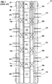
- FIG. 1 Representatively illustrated in FIG. 1 is a well control system 10 which is used to illustrate the types of problems overcome by the systems and methods of the present disclosure. Although the drawing depicts prior art concepts, it is not meant to imply that any particular prior art well control system included the exact configuration illustrated in FIG. 1 .
- the control system 10 as depicted in FIG. 1 is used to control production flow from multiple zones 12a-e intersected by a wellbore 14.
- the wellbore 14 has been cased and cemented, and the zones 12a-e are isolated within a casing string 16 by packers 18a-e carried on a production tubing string 20.
- Fluid communication between the zones 12a-e and the interior of the tubing string 20 is controlled by means of flow control devices 22a-e interconnected in the tubing string.
- the flow control devices 22a-e have respective actuators 24a-e for actuating the flow control devices open, closed or in a flow choking position between open and closed.
- the control system 10 is hydraulically operated, and the actuators 24a-e are relatively simple piston-and-cylinder actuators.
- Each actuator 24a-e is connected to two hydraulic lines -- a balance line 26 and a respective one of multiple control lines 28a-e.
- a pressure differential between the balance line 26 and the respective control line 28a-e is applied from a remote location (such as the earth's surface, a subsea wellhead, etc.) to displace the piston of the corresponding actuator 24a-e and thereby actuate the associated flow control device 22a-e, with the direction of displacement being dependent on the direction of the pressure differential.
- Another problem is that it is difficult to precisely control pressure differentials between lines extending perhaps a thousand or more meters into the earth. This will lead to improper or unwanted actuation of the devices 22a-e, as well as imprecise regulation of flow from the zones 12a-e.
- control modules for selectively actuating the devices 22a-e.
- these control modules include sensitive electronics which are frequently damaged by the hostile downhole environment (high temperature and pressure, etc.).
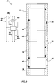
- FIG. 2 a system 30 and associated method for selectively actuating multiple well tools 32 are representatively illustrated. Only a single well tool 32 is depicted in FIG. 2 for clarity of illustration and description, but the manner in which the system 30 may be used to selectively actuate multiple well tools is described more fully below.
- the well tool 32 in this example is depicted as including a flow control device 38 (such as a valve or choke), but other types or combinations of well tools may be selectively actuated using the principles of this disclosure, if desired.
- a sliding sleeve 34 is displaced upwardly or downwardly by an actuator 36 to open or close ports 40.
- the sleeve 34 can also be used to partially open the ports 40 and thereby variably restrict flow through the ports.
- the actuator 36 includes an annular piston 42 which separates two chambers 44, 46.
- the chambers 44, 46 are connected to lines 48a,b via a control device 50.
- D.C. current flow in a set of electrical conductors 52a,b is used to select whether the well tool 32 is to be actuated in response to a pressure differential between the lines 48a,b.
- the well tool 32 is selected for actuation by flowing current between the conductors 52a,b in a first direction 54a (in which case the chambers 44, 46 are connected to the lines 48a,b), but the well tool 32 is not selected for actuation when current flows between the conductors 52a,b in a second, opposite, direction 54b (in which case the chambers 44, 46 are isolated from the lines 48a,b).
- Various configurations of the control device 50 are described below for accomplishing this result. These control device 50 configurations are advantageous in that they do not require complex, sensitive or unreliable electronics or mechanisms, but are instead relatively simple, economical and reliable in operation.
- the well tool 32 may be used in place of any or all of the flow control devices 22a-e and actuators 24a-e in the system 10 of FIG. 1 .
- the principles of this disclosure could also be used to control actuation of other well tools, such as selective setting of the packers 18a-e, etc.
- hydraulic lines 48a,b are representative of one type of fluid pressure source 48 which may be used in keeping with the principles of this disclosure. It should be understood that other fluid pressure sources (such as pressure within the tubing string 20, pressure in an annulus 56 between the tubing and casing strings 20, 16, pressure in an atmospheric or otherwise pressurized chamber, etc., may be used as fluid pressure sources in conjunction with the control device 50 for supplying pressure to the actuator 36 in other embodiments.
- fluid pressure sources such as pressure within the tubing string 20, pressure in an annulus 56 between the tubing and casing strings 20, 16, pressure in an atmospheric or otherwise pressurized chamber, etc.
- the conductors 52a,b comprise a set of conductors 52 through which current flows, and this current flow is used by the control device 50 to determine whether the associated well tool 32 is selected for actuation.
- Two conductors 52a,b are depicted in FIG. 2 as being in the set of conductors 52, but it should be understood that any number of conductors may be used in keeping with the principles of this disclosure.
- the conductors 52a,b can be in a variety of forms, such as wires, metal structures (for example, the casing or tubing strings 16, 20, etc.), or other types of conductors.
- the conductors 52a,b preferably extend to a remote location (such as the earth's surface, a subsea wellhead, another location in the well, etc.).
- a surface power supply and multiplexing controller can be connected to the conductors 52a,b for flowing current in either direction 54a,b between the conductors.
- n conductors can be used to selectively control actuation of n*(n-1) well tools.
- the benefits of this arrangement quickly escalate as the number of well tools increases. For example, three conductors may be used to selectively actuate six well tools, and only one additional conductor is needed to selectively actuate twelve well tools.
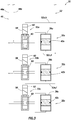
- FIG. 3 a somewhat more detailed illustration of the electrical and hydraulic aspects of one example of the system 30 are provided.
- FIG. 3 provides for additional explanation of how multiple well tools 32 may be selectively actuated using the principles of this disclosure.
- control devices 50a-c are associated with respective multiple actuators 36a-c of multiple well tools 32a-c. It should be understood that any number of control devices, actuators and well tools may be used in keeping with the principles of this disclosure, and that these elements may be combined, if desired (for example, multiple control devices could be combined into a single device, a single well tool can include multiple functional well tools, an actuator and/or control device could be built into a well tool, etc.).
- Each of the control devices 50a-c depicted in FIG. 3 includes a solenoid actuated spool valve.
- a solenoid 58 of the control device 50a has displaced a spool or poppet valve 60 to a position in which the actuator 36a is now connected to the lines 48a,b.
- a pressure differential between the lines 48a,b can now be used to displace the piston 42a and actuate the well tool 32a.
- the remaining control devices 50b,c prevent actuation of their associated well tools 32b,c by isolating the lines 48a,b from the actuators 36b,c.
- the control device 50a responds to current flow through a certain set of the conductors 52.
- conductors 52a,b are connected to the control device 50a.
- the control device 50a When current flows in one direction through the conductors 52a,b, the control device 50a causes the actuator 36a to be operatively connected to the lines 48a,b, but when current flows in an opposite direction through the conductors, the control device causes the actuator to be operatively isolated from the lines.
- control device 50b is connected to conductors 52c,d and control device 50c is connected to conductors 52e,f.
- the control device 50b When current flows in one direction through the conductors 52c,d, the control device 50b causes the actuator 36b to be operatively connected to the lines 48a,b, but when current flows in an opposite direction through the conductors, the control device causes the actuator to be operatively isolated from the lines.
- the control device 50c when current flows in one direction through the conductors 52e,f, the control device 50c causes the actuator 36c to be operatively connected to the lines 48a,b, but when current flows in an opposite direction through the conductors, the control device causes the actuator to be operatively isolated from the lines.
- control devices are preferably, but not necessarily, connected to each set of conductors.
- the advantages of a reduced number of conductors can be obtained, as explained more fully below.
- directional elements 62 of the control devices 50a-c.
- Various different types of directional elements 62 are described more fully below.
- FIG. 4 an example of the system 30 is representatively illustrated, in which multiple control devices are connected to each of multiple sets of conductors, thereby achieving the desired benefit of a reduced number of conductors in the well.
- actuation of six well tools may be selectively controlled using only three conductors, but, as described herein, any number conductors and well tools may be used in keeping with the principles of this disclosure.
- control devices 50a-f are illustrated apart from their respective well tools. However, it will be appreciated that each of these control devices 50a-f would in practice be connected between the fluid pressure source 48 and a respective actuator 36 of a respective well tool 32 (for example, as described above and depicted in FIGS. 2 & 3 ).
- the control devices 50a-f include respective solenoids 58a-f, spool valves 60a-f and directional elements 62a-f.
- the elements 62a-f are diodes.
- the solenoids 58a-f and diodes 62a-f are electrical components, they do not comprise complex or unreliable electronic circuitry, and suitable reliable high temperature solenoids and diodes are readily available.
- a power supply 64 is used as a source of direct current.
- the power supply 64 could also be a source of alternating current and/or command and control signals, if desired.
- the system 30 as depicted in FIG. 4 relies on directional control of current in the conductors 52 in order to selectively actuate the well tools 32, so alternating current, signals, etc. should be present on the conductors only if such would not interfere with this selection function.
- the power supply 64 comprises a floating power supply.
- the conductors 52 may also be used for telemetry, for example, to transmit and receive data and commands between the surface and downhole well tools, actuators, sensors, etc. This telemetry can be conveniently transmitted on the same conductors 52 as the electrical power supplied by the power supply 64.
- the conductors 52 in this example comprise three conductors 52a-c.
- the conductors 52 are also arranged as three sets of conductors 52a,b 52b,c and 52a,c.
- Each set of conductors includes two conductors. Note that a set of conductors can share one or more individual conductors with another set of conductors.
- Each conductor set is connected to two control devices.
- conductor set 52a,b is connected to each of control devices 50a,b
- conductor set 52b,c is connected to each of control devices 50c,d
- conductor set 52a,c is connected to each of control devices 50e,f.
- tubing string 20 is part of the conductor 52c.
- casing string 16 or any other conductor can be used in keeping with the principles of this disclosure.
- diode 62a will prevent solenoid 58a from being powered due to current flow from conductor 52b to conductor 52a
- diode 62b will prevent solenoid 58b from being powered due to current flow from conductor 52a to conductor 52b.
- the direction of current flow between the conductors 52 is controlled by means of a switching device 66.
- the switching device 66 is interconnected between the power supply 64 and the conductors 52, but the power supply and switching device could be combined, or could be part of an overall control system, if desired.
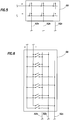
- FIGS. 5 & 6 Examples of different configurations of the switching device 66 are representatively illustrated in FIGS. 5 & 6.
- FIG. 5 depicts an embodiment in which six independently controlled switches are used to connect the conductors 52a-c to the two polarities of the power supply 64.
- FIG. 6 depicts an embodiment in which an appropriate combination of switches are closed to select a corresponding one of the well tools for actuation. This embodiment might be implemented, for example, using a rotary switch. Other implementations (such as using a programmable logic controller, etc.) may be utilized as desired.
- FIG. 7 another configuration of the control system 30 is representatively illustrated.
- the configuration of FIG. 7 is similar in many respects to the configuration of FIG. 3 .
- only two each of the actuators 36a,b and control devices 50a,b, and one set of conductors 52a,b are depicted in FIG. 7 , it being understood that any number of actuators, control devices and sets of conductors may be used in keeping with the principles of this disclosure.
- FIGS. 3 & 7 configurations Another difference between the FIGS. 3 & 7 configurations is in the spool valves 60a,b.
- the spool valves 60 in the FIGS. 3 & 7 configurations accomplish similar results, but in somewhat different manners.
- the spool valves 60 pressure balance the pistons 42 when the solenoids 58 are not powered, and they connect the actuators 36 to the pressure source 48 when the solenoids 58 are powered.
- the actuators 36 are completely isolated from the pressure source 48 when the solenoids 58 are not powered, whereas in the FIG. 7 configuration, the actuators remain connected to one of the lines 48b when the solenoids are not powered.
- pressure-compensated flow rate regulators 68a,b are connected between the line 48a and respective spool valves 60a,b.
- the flow regulators 68a,b maintain a substantially constant flow rate therethrough, even though pressure differential across the flow regulators may vary.
- a suitable flow regulator for use in the system 30 is a FLOSERT(tm) available from Lee Co. of Essex, Connecticut USA.
- the flow regulator 68a or b will ensure that the piston displaces at a predetermined velocity, since fluid will flow through the flow regulator at a corresponding predetermined flow rate.
- the position of the piston can be precisely controlled (i.e., by permitting the piston to displace at its predetermined velocity for a given amount of time, which can be precisely controlled via the control device due to the presence and direction of current flow in the conductors 52 as described above).
- flow regulators 68a,b are depicted in FIG. 7 as being connected between the line 48a and the respective spool valves 60a,b, it will be appreciated that other arrangements are possible.
- the flow regulators 68a,b could be connected between the line 48b and the spool valves 60a,b, or between the spool valves and the actuators 36a,b, etc.
- the flow regulators may be used in any of the other control system 30 configurations described herein, if desired, in order to allow for precise control of the positions of the pistons in the actuators. Such positional control is very useful in flow choking applications, for example, to precisely regulate production or injection flow between multiple zones and a tubing string.
- the conductor 52b includes the tubing string 20. This demonstrates that any of the conductors 52 can comprise a tubular string in the well.
- FIG. 8 another configuration of the control system 30 is representatively illustrated.
- the configuration of FIG. 8 is similar in many respects to the configuration of FIG. 7 , but differs substantially in the manner in which the control devices 50a,b operate.
- the spool valves 60a,b are pilot-operated, with the solenoids 58a,b serving to selectively permit or prevent such pilot operation.
- powering of a respective one of the solenoids 58a,b still operates to select a particular one of the well tools 32 for actuation, but the amount of power required to do so is expected to be much less in the FIG. 8 embodiment.
- the solenoid 58a is powered by current flow from conductor 52a to conductor 52b, the solenoid will cause a locking member 70a to retract out of locking engagement with a piston 72a of the spool valve 60a.
- the piston 72a will then be free to displace in response to a pressure differential between the lines 48a,b. If, for example, pressure in the line 48a is greater than pressure in the line 48b, the piston 72a will displace to the right as viewed in FIG. 8 , thereby connecting the actuator 36a to the pressure source 48, and the piston 42a of the actuator 36a will displace to the right.
- the actuator 36a is pressure balanced.
- the solenoid 58b is powered by current flow from conductor 52b to conductor 52a, the solenoid will cause a locking member 70b to retract out of locking engagement with a piston 72b of the spool valve 60b.
- the piston 72b will then be free to displace in response to a pressure differential between the lines 48a,b. If, for example, pressure in the line 48b is greater than pressure in the line 48a, the piston 72b will displace to the left as viewed in FIG. 8 , thereby connecting the actuator 36b to the pressure source 48, and the piston 42b of the actuator 36b will displace to the left. However, when the piston 72b is in its centered and locked position, the actuator 36b is pressure balanced.
- the locking engagement between the locking members 70a,b and the pistons 72a,b could be designed to release in response to a predetermined pressure differential between the lines 48a,b (preferably, a pressure differential greater than that expected to be used in normal operation of the system 30).
- the actuators 36a,b could be operated by applying the predetermined pressure differential between the lines 48a,b, for example, in the event that one or both of the solenoids 58a,b failed to operate, in an emergency to quickly close the flow control devices 38, etc.
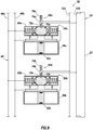
- FIG. 9 another configuration of the control system 30 is representatively illustrated.
- the FIG. 9 configuration is similar in many respects to the FIG. 8 configuration, except that the solenoids and diodes are replaced by coils 74a,b and magnets 76a,b in the control devices 50a,b of FIG. 9 .
- the coils 74a,b and magnets 76a,b also comprise the directional elements 62a,b in the control devices 50a,b since the respective locking members 70a,b will only displace if current flows between the conductors 52a,b in appropriate directions.
- the coil 74a and magnet 76a are arranged so that, if current flows from conductor 52a to conductor 52b, the coil will generate a magnetic field which opposes the magnetic field of the magnet, and the locking member 70a will thus be displaced upward (as viewed in FIG. 9 ) out of locking engagement with the piston 72a, and the actuator 36a can be connected to the pressure source 48 as described above. Current flow in the opposite direction will not cause such displacement of the locking member 70a.
- the coil 74b and magnet 76b are arranged so that, if current flows from conductor 52b to conductor 52a, the coil will generate a magnetic field which opposes the magnetic field of the magnet, and the locking member 70b will thus be displaced upward (as viewed in FIG. 9 ) out of locking engagement with the piston 72b, and the actuator 36b can be connected to the pressure source 48 as described above. Current flow in the opposite direction will not cause such displacement of the locking member 70b.
- FIG. 9 configuration obtains all of the benefits of the previously described configurations, but does not require use of any downhole electrical components, other than the coils 74a,b and conductors 52.
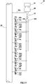
- FIG. 10 another configuration of the control system 30 is representatively illustrated.
- the FIG. 10 configuration is similar in many respects to the FIG. 9 configuration, but is depicted with six of the control devices 50a-f and three sets of the conductors 52, similar to the system 30 as illustrated in FIG. 4 .
- the spool valves 60, actuators 36 and well tools 32 are not shown in FIG. 10 for clarity of illustration and description.
- the coils 74a-f and magnets 76a-f are arranged so that selected locking members 70a-f are displaced in response to current flow in particular directions between certain conductors in the sets of the conductors 52.
- current flow between the conductors 52a,b in one direction may cause the element 62a to displace the locking member 70a while current flow between the conductors 52a,b in an opposite direction may cause the element 62b to displace the locking member 70b
- current flow between the conductors 52b,c may cause the element 62c to displace the locking member 70c while current flow between the conductors 52b,c may cause the element 62d to displace the locking member 70d
- current flow between the conductors 52a,c may cause the element 62e to displace the locking member 70e while current flow between the conductors 52a,c in an opposite direction may cause the element 62f to displace the locking member 70f.
- the magnets 76a,b 70c,d and 70e,f are oppositely oriented (i.e., with their poles facing opposite directions in each pair of control devices). This alternating orientation of the magnets 76a-f, combined with the connection of the coils 74a-f to particular sets of the conductors 52, results in the capability of selecting a particular well tool 32 for actuation by merely flowing current in a particular direction between particular ones of the conductors.
- FIG. 11 Another manner of achieving this result is representatively illustrated in FIG. 11 .
- the coils 74a-f are oppositely arranged in the pairs of control devices 50a,b 50c,d and 50e,f.
- the coils 74a-f could be wound in opposite directions, so that opposite magnetic field orientations are produced when current flows between the sets of conductors.
- Another manner of achieving this result would be to oppositely connect the coils 74a-f to the respective conductors 52.
- current flow between a set of conductors would produce a magnetic field in one orientation from one of the coils, but a magnetic field in an opposite orientation from the other one of the coils.
- the above description has provided a method of selectively actuating from a remote location multiple downhole well tools 32 in a well.
- the method includes the steps of: selecting one of the well tools 32a for actuation by flowing electrical current in one direction 54a through a set of conductors 52a,b in the well; and selecting another one of the well tools 32b for actuation by flowing electrical current through the set of conductors 52a,b in an opposite direction 54b.
- the step of selecting the first well tool 32a may include providing fluid communication between a source of fluid pressure 48 and an actuator 36a of the first well tool 32a.
- the step of selecting the second well tool 32b may include providing fluid communication between the source of fluid pressure 48 and an actuator 36b of the second well tool 32b.
- the method may include the step of flowing fluid between the source of fluid pressure 48 and the actuator 36a of the first well tool 32a for a predetermined period of time through a flow rate regulator 68a, thereby displacing a piston 42a of the actuator 36a of the first well tool 32a a predetermined distance.
- the flow rate regulator 68a may substantially maintain a predetermined rate of flow of the fluid as a pressure differential across an input and an output of the flow rate regulator varies over time.
- the method may also include the steps of preventing the first well tool 32a from actuating while current flows between the conductors 52a,b in the second direction, and preventing the second well tool 32b from actuating while current flows between the conductors 52a,b in the first direction.
- the step of preventing the first well tool 32a from actuating may include using a first diode 62a to prevent current flow in the second direction 54b
- the step of preventing the second well tool 32b from actuating may include using a second diode 62b to prevent current flow in the first direction 54a.
- the method may also include the steps of selecting a third one of the well tools 32 for actuation by flowing electrical current in a third direction through a second set of conductors 52b,c in the well; and selecting a fourth one of the well tools 32 for actuation by flowing electrical current through the second set of conductors 52b,c in a fourth direction opposite to the third direction.
- the above description also provides a system 30 for selectively actuating from a remote location multiple downhole well tools 32 in a well.
- the system 30 includes multiple electrical conductors 52 in the well and multiple control devices 50 which control which of the well tools 32 is selected for actuation in response to current flow in at least one set of the conductors 52. At least one direction of current flow in the set of conductors 52 is used to select a respective at least one of the well tools 32 for actuation. An opposite direction of current flow in the set of conductors 52 may be used to select a respective other one of the well tools 32 for actuation.
- the control devices 50 may include multiple diodes 62.
- a first one of the diodes 62a may be used to permit actuation of a first one of the well tools 32a in response to current flow in a first direction between a first set of the conductors 52a,b.
- a second one of the diodes 62b may be used to permit actuation of a second one of the well tools 32b in response to current flow in a second direction between the first set of the conductors 52a,b with the second direction being opposite to the first direction.
- the first diode 62a may prevent actuation of the first well tool 32a when current flows in the second direction between the first set of conductors 52a,b.
- the second diode 62b may prevent actuation of the second well tool 32b when current flows in the first direction between the first set of conductors 52a,b.
- the control devices 50 may include multiple coil and magnet sets.
- a first coil 74a and magnet 76a set may be used to permit actuation of a first one of the well tools 32a in response to current flow in a first direction between a first set of the conductors 52a,b and a second coil 74b and magnet 76b set may be used to permit actuation of a second one of the well tools 32b in response to current flow in a second direction between the first set of the conductors 52a,b with the second direction being opposite to the first direction.
- the first coil 74a and magnet 76a set may prevent actuation of the first well tool 32a when current flows in the second direction between the first set of conductors 52a,b.
- the second coil 74b and magnet 76b set may prevent actuation of the second well tool 32b when current flows in the first direction between the first set of conductors 52a,b.
- the system 30 may also include at least one hydraulic line 48a,b in the well and multiple actuators 36.
- Each of the actuators 36 may be responsive to fluid pressure in the at least one hydraulic line 48a,b to actuate a respective one of the well tools 32.
- Each of the actuators 36 may be isolated from pressure in the hydraulic line 48a,b until the current flow in the set of conductors 52 flows in a respective predetermined direction.
- the well tools 32 may include at least first, second, third and fourth well tools
- the control devices 50 may include at least first, second, third and fourth control devices
- the sets of conductors 52 may include at least first and second sets of conductors.
- the first control device 50a may be configured to select the first well tool 32a for actuation in response to current flow in a first direction between the first set of conductors 52a,b
- the second control device 50b may be configured to select the second well tool 32b for actuation in response to current flow between the first set of conductors 52a,b in a second direction opposite to the first direction
- the third control device 50c may be configured to select the third well tool 32c for actuation in response to current flow between the second set of conductors 52b,c in a third direction
- the fourth control device 50d may be configured to select the fourth well tool for actuation in response to current flow between the second set of conductors 52b,c in a fourth direction opposite to the third direction.
- Telemetry signals may be transmitted via at least one of the conductors 52.
- n conductors 52 to selectively actuate n*(n-1) downhole well tools 32.
- the method includes the steps of: arranging the n conductors 52 into n*(n-1)/2 sets of conductors; connecting each set of conductors 52 to a respective pair of the well tools 32; and controlling direction of current flow through each set of conductors 52 to thereby selectively actuate the respective pair of the well tools 32.
- the controlling step may include selecting a first one of the well tools 32a for actuation by flowing electrical current in a first direction between a first one of the sets of conductors 52a,b; and selecting a second one of the well tools 32b for actuation by flowing electrical current between the first set of conductors 52a,b in a second direction opposite to the first direction.
- the step of selecting the first well tool 32a further comprises providing fluid communication between a source of fluid pressure 48 and an actuator 36a of the first well tool 32a.
- the step of selecting the second well tool 32b may include providing fluid communication between the source of fluid pressure 48 and an actuator 36b of the second well tool 32b.
- the method may include the step of flowing fluid between the source of fluid pressure 48 and the actuator 36a of the first well tool 32a for a predetermined period of time through a flow rate regulator 68a, thereby displacing a piston 42a of the actuator 36a of the first well tool 32a a predetermined distance.
- the method may include the steps of preventing the first well tool 32a from actuating while current flows between the conductors 52a,b in the second direction, and preventing the second well tool 32b from actuating while current flows between the conductors 52a,b in the first direction.
- the step of preventing the first well tool 32a from actuating may include using a first diode 62a to prevent current flow in the second direction.
- the step of preventing the second well tool 32b from actuating may include using a second diode 62b to prevent current flow in the first direction.
- the method may include the steps of selecting a third one of the well tools 32c for actuation by flowing electrical current in a third direction between a second set of conductors 52b,c in the well; and selecting a fourth one of the well tools for actuation by flowing electrical current between the second set of conductors 52b,c in a fourth direction opposite to the third direction.
- multiple well tools 32 may be selected for actuation at the same time.
- multiple similarly configured control devices 50 could be wired in series or parallel to the same set of the conductors 52, or control devices connected to different sets of conductors could be operated at the same time by flowing current in appropriate directions through the sets of conductors.
- fluid pressure to actuate the well tools 32 may be supplied by one of the lines 48, and another one of the lines (or another flow path, such as an interior of the tubing string 20 or the annulus 56) may be used to exhaust fluid from the actuators 36.
- An appropriately configured and connected spool valve can be used, so that the same one of the lines 48 be used to supply fluid pressure to displace the pistons 42 of the actuators 36 in each direction.
- the fluid pressure source 48 is pressurized prior to flowing current through the selected set of conductors 52 to actuate a well tool 32.
- actuation of the well tool 32 immediately follows the initiation of current flow in the set of conductors 52.
Landscapes
- Engineering & Computer Science (AREA)
- Geology (AREA)
- Mining & Mineral Resources (AREA)
- Life Sciences & Earth Sciences (AREA)
- Physics & Mathematics (AREA)
- General Life Sciences & Earth Sciences (AREA)
- Fluid Mechanics (AREA)
- Environmental & Geological Engineering (AREA)
- Geochemistry & Mineralogy (AREA)
- Geophysics (AREA)
- Remote Sensing (AREA)
- Fluid-Pressure Circuits (AREA)
- Operation Control Of Excavators (AREA)
- Excavating Of Shafts Or Tunnels (AREA)
- Magnetically Actuated Valves (AREA)
Claims (11)
- Procédé d'activation sélective à partir d'un emplacement distant de multiples outils de puits de fond de trou (32) dans un puits, le procédé comprenant les étapes suivantes :la sélection d'un premier (32a) des outils de puits pour l'activation en faisant circuler un courant électrique dans une première direction à travers un premier jeu de conducteurs (52a, 52b) dans le puits et fournissant une communication fluide entre une source de pression de fluide (48) et un actionneur (36a) du premier outil de puits ;l'écoulement de fluide entre la source de pression de fluide et l'actionneur du premier outil de puits pendant une période de temps prédéterminée à travers un premier débitmètre (68a), déplaçant ainsi un piston (42a) de l'actionneur du premier outil de puits sur une distance prédéterminée ;la sélection d'un deuxième (32b) des outils de puits pour l'activation en faisant circuler un courant électrique à travers le premier jeu de conducteurs dans une deuxième direction à l'opposé de la première direction et en fournissant une communication fluide entre la source de pression de fluide et un actionneur (36b) du deuxième outil de puits ; caractérisé par :et l'écoulement de fluide entre la source de pression de fluide et l'actionneur du deuxième outil de puits pendant une période de temps prédéterminée à travers un second débitmètre (68b), déplaçant ainsi un piston (42b) de l'actionneur du deuxième outil de puits sur une distance prédéterminée.
- Procédé selon la revendication 1, dans lequel le débitmètre maintient sensiblement un débit prédéterminé du fluide lorsqu'une différence de pression à travers une entrée et une sortie du débitmètre varie au cours du temps.
- Procédé selon la revendication 1, comprenant également les étapes de prévention de l'activation du premier outil de puits lorsque le courant circule à travers les conducteurs dans la deuxième direction, et la prévention de l'activation du deuxième outil de puits lorsque le courant circule à travers les conducteurs dans la première direction et, de préférence, dans lequel l'étape de prévention de l'activation du premier outil de puits comprend également l'utilisation d'une première diode pour empêcher la circulation de courant dans la deuxième direction, et dans lequel l'étape de prévention de l'activation du deuxième outil de puits comprend également l'utilisation d'une seconde diode pour empêcher la circulation de courant dans la première direction.
- Procédé selon la revendication 1, comprenant également les étapes de sélection d'un troisième des outils de puits pour l'activation en faisant circuler un courant électrique dans une troisième direction à travers un second jeu de conducteurs dans le puits ; et la sélection d'un quatrième des outils de puits pour l'activation en faisant circuler un courant électrique à travers le second jeu de conducteurs dans une quatrième direction à l'opposé de la troisième direction.
- Système d'activation sélective à partir d'un emplacement distant de multiples outils de puits de fond de trou (32) dans un puits, le système comprenant :de multiples conducteurs électriques dans le puits (52) ; etde multiples dispositifs de commande (50) qui commandent lequel des outils de puits est sélectionné pour l'activation en réponse à la circulation de courant dans au moins un jeu des conducteurs (52a, 52b),comprenant également au moins une ligne hydraulique (48a, 48b) dans le puits ; et de multiples actionneurs (36a), au moins un clapet (60a) et au moins un débitmètre (68a) ;dans lequel chaque actionneur est relié à un de l'au moins une des lignes hydrauliques, et chaque débitmètre est relié entre l'une de l'au moins une des lignes hydrauliques et un de l'au moins un des clapets ;dans lequel chacun des actionneurs étant sensible à la pression de fluide dans l'au moins une ligne hydraulique pour activer l'un des outils de puits respectif,dans lequel chacun des actionneurs comprend un piston d'actionneur (42a) qui est équilibré en pression par l'un de l'au moins un écoulement de clapet jusqu'à ce que la circulation de courant dans le jeu de conducteurs circule dans une direction prédéterminée respective ;dans lequel le piston d'actionneur peut être déplacé sur une distance prédéterminée en réponse à un écoulement de fluide entre l'une de l'au moins une des lignes hydrauliques et l'actionneur à travers l'au moins un débitmètre pendant une période de temps prédéterminée ; etdans lequel au moins une direction de la circulation de courant dans l'au moins un jeu de conducteurs étant fonctionnel pour sélectionner au moins un des outils de puits respectif pour l'activation, et dans lequel l'outil de puits est activé par le déplacement du piston d'actionneur sur la distance prédéterminée.
- Système selon la revendication 5, dans lequel les dispositifs de commande comprennent de multiples diodes (62a, 62b), une première des diodes étant fonctionnelle pour permettre l'activation d'un premier des outils de puits en réponse à la circulation de courant dans une première direction à travers un premier jeu des conducteurs, et une deuxième des diodes étant fonctionnelle pour permettre l'activation d'un deuxième des outils de puits en réponse à la circulation de courant dans une deuxième direction à travers le premier jeu de conducteurs, la deuxième direction étant à l'opposé de la première direction et, de préférence, dans lequel la première diode empêche l'activation du premier outil de puits lorsque le courant circule dans la deuxième direction à travers le premier jeu de conducteurs, et dans lequel la seconde diode empêche l'activation du deuxième outil de puits lorsque le courant circule dans la première direction à travers le premier jeu de conducteurs.
- Système selon la revendication 5, dans lequel les outils de puits comprennent au moins un premier, un deuxième, un troisième et un quatrième outils de puits (32a-d), dans lequel les dispositifs de commande comprennent au moins un premier, un deuxième, un troisième et un quatrième dispositifs de commande (50a-d), dans lequel les jeux de conducteurs comprennent au moins un premier et un second jeux de conducteurs (52a, 52b, 52c, 52d), et dans lequel le premier dispositif de commande est conçu pour sélectionner le premier outil de puits pour l'activation en réponse à la circulation de courant dans une première direction à travers le premier jeu de conducteurs, le deuxième dispositif de commande est conçu pour sélectionner le deuxième outil de puits pour l'activation en réponse à la circulation de courant à travers le premier jeu de conducteurs dans une deuxième direction à l'opposé de la première direction, le troisième dispositif de commande est conçu pour sélectionner le troisième outil de puits pour l'activation en réponse à la circulation de courant à travers le second jeu de conducteurs dans une troisième direction, et le quatrième dispositif de commande est conçu pour sélectionner le quatrième outil de puits pour l'activation en réponse à la circulation de courant à travers le second jeu de conducteurs dans une quatrième direction à l'opposé de la troisième direction.
- Système selon la revendication 5, dans lequel les signaux de télémétrie sont transmis à travers au moins l'un des conducteurs.
- Procédé selon l'une quelconque des revendications 1, 3 et 4, dans lequel il y a n conducteurs agencés en n(n-1)/2 jeux de conducteurs, et le premier et le second jeux de conducteurs sont choisis parmi les n(n-1)/2 jeux de conducteurs ;
le procédé étant ainsi en mesure d'utiliser n conducteurs pour sélectivement actionner n(n-1)/2 outils de puits de fond de trou. - Procédé selon la revendication 9, comprenant également les étapes de prévention de l'activation du premier outil de puits lorsque le courant circule à travers les conducteurs dans la deuxième direction, et la prévention de l'activation du deuxième outil de puits lorsque le courant circule à travers les conducteurs dans la première direction et, de préférence, dans lequel l'étape de prévention de l'activation du premier outil de puits comprend également l'utilisation d'une première diode pour empêcher la circulation de courant dans la deuxième direction, et dans lequel l'étape de prévention de l'activation du deuxième outil de puits comprend également l'utilisation d'une seconde diode pour empêcher la circulation de courant dans la première direction.
- Procédé selon la revendication 9, comprenant également les étapes de sélection d'un troisième des outils de puits pour l'activation en faisant circuler un courant électrique dans une troisième direction à travers un second jeu de conducteurs dans le puits ; et la sélection d'un quatrième des outils de puits pour l'activation en faisant circuler un courant électrique à travers le second jeu de conducteurs dans une quatrième direction à l'opposé de la troisième direction.
Applications Claiming Priority (1)
| Application Number | Priority Date | Filing Date | Title |
|---|---|---|---|
| PCT/US2008/075668 WO2010030266A1 (fr) | 2008-09-09 | 2008-09-09 | Actionnement à distance d’outils de forage de puits |
Publications (3)
| Publication Number | Publication Date |
|---|---|
| EP2321493A1 EP2321493A1 (fr) | 2011-05-18 |
| EP2321493A4 EP2321493A4 (fr) | 2015-04-15 |
| EP2321493B1 true EP2321493B1 (fr) | 2018-02-21 |
Family
ID=42005358
Family Applications (2)
| Application Number | Title | Priority Date | Filing Date |
|---|---|---|---|
| EP08799341.6A Not-in-force EP2321493B1 (fr) | 2008-09-09 | 2008-09-09 | Actionnement a distance d'outils de forage de puits |
| EP09813522.1A Not-in-force EP2331987B1 (fr) | 2008-09-09 | 2009-09-09 | Système de commande multiplexe à indication de position pour outils de fond de puits |
Family Applications After (1)
| Application Number | Title | Priority Date | Filing Date |
|---|---|---|---|
| EP09813522.1A Not-in-force EP2331987B1 (fr) | 2008-09-09 | 2009-09-09 | Système de commande multiplexe à indication de position pour outils de fond de puits |
Country Status (6)
| Country | Link |
|---|---|
| US (2) | US8322446B2 (fr) |
| EP (2) | EP2321493B1 (fr) |
| BR (2) | BRPI0822766A2 (fr) |
| CA (2) | CA2735427C (fr) |
| NO (1) | NO2321493T3 (fr) |
| WO (2) | WO2010030266A1 (fr) |
Families Citing this family (24)
| Publication number | Priority date | Publication date | Assignee | Title |
|---|---|---|---|---|
| US8196656B2 (en) | 2007-09-19 | 2012-06-12 | Welldynamics, Inc. | Position sensor for well tools |
| BRPI0913461B1 (pt) | 2008-09-09 | 2019-04-02 | Halliburton Energy Services Inc | Sistema e método para atuar seletivamente de uma localização remota múltiplas ferramentas de poço dentro do poço em um poço |
| NO2321493T3 (fr) | 2008-09-09 | 2018-07-21 | ||
| US8590609B2 (en) | 2008-09-09 | 2013-11-26 | Halliburton Energy Services, Inc. | Sneak path eliminator for diode multiplexed control of downhole well tools |
| GB0818010D0 (en) * | 2008-10-02 | 2008-11-05 | Petrowell Ltd | Improved control system |
| US8602658B2 (en) * | 2010-02-05 | 2013-12-10 | Baker Hughes Incorporated | Spoolable signal conduction and connection line and method |
| US8397828B2 (en) * | 2010-03-25 | 2013-03-19 | Baker Hughes Incorporated | Spoolable downhole control system and method |
| US8476786B2 (en) | 2010-06-21 | 2013-07-02 | Halliburton Energy Services, Inc. | Systems and methods for isolating current flow to well loads |
| AU2011305004A1 (en) | 2010-09-22 | 2013-04-04 | Packers Plus Energy Services Inc. | Wellbore frac tool with inflow control |
| BR112014005570A2 (pt) * | 2011-09-12 | 2017-03-21 | Packers Plus Energy Serv Inc | ferramenta de fraturar poço com controle de influxo |
| US9127526B2 (en) | 2012-12-03 | 2015-09-08 | Halliburton Energy Services, Inc. | Fast pressure protection system and method |
| US9695654B2 (en) | 2012-12-03 | 2017-07-04 | Halliburton Energy Services, Inc. | Wellhead flowback control system and method |
| US9388664B2 (en) * | 2013-06-27 | 2016-07-12 | Baker Hughes Incorporated | Hydraulic system and method of actuating a plurality of tools |
| US9790768B2 (en) * | 2015-07-15 | 2017-10-17 | Baker Hughes Incorporated | Apparatus to activate a downhole tool by way of electromagnets via wireline current |
| US10337270B2 (en) * | 2015-12-16 | 2019-07-02 | Neo Products, LLC | Select fire system and method of using same |
| BR112019002981A2 (pt) * | 2016-09-22 | 2019-05-14 | Halliburton Energy Services Inc | sistema de sensor de posição para um sistema de poço, e, método para determinar uma posição de uma ferramenta de fundo de poço |
| US11591884B2 (en) | 2017-06-08 | 2023-02-28 | Schlumberger Technology Corporation | Hydraulic indexing system |
| US11332992B2 (en) | 2017-10-26 | 2022-05-17 | Non-Explosive Oilfield Products, Llc | Downhole placement tool with fluid actuator and method of using same |
| GB2580809B (en) | 2017-11-17 | 2022-03-02 | Halliburton Energy Services Inc | Actuator for multilateral wellbore system |
| US11536112B2 (en) * | 2019-02-05 | 2022-12-27 | Schlumberger Technology Corporation | System and methodology for controlling actuation of devices downhole |
| US20200248533A1 (en) * | 2019-02-05 | 2020-08-06 | Schlumberger Technology Corporation | System and methodology for selective actuation of a downhole device |
| US11293278B2 (en) * | 2020-04-22 | 2022-04-05 | Halliburton Energy Services, Inc. | Valve position sensing using electric and magnetic coupling |
| US20220235630A1 (en) | 2021-01-26 | 2022-07-28 | Halliburton Energy Services, Inc. | Low power consumption electro-hydraulic valve controller |
| US11732577B2 (en) | 2021-05-26 | 2023-08-22 | Halliburton Energy Services, Inc. | Downhole multiplexed electrical system |
Family Cites Families (54)
| Publication number | Priority date | Publication date | Assignee | Title |
|---|---|---|---|---|
| US2984985A (en) * | 1959-02-16 | 1961-05-23 | Macmillin Hydraulic Engineerin | Hydraulic operating and control system |
| US3105551A (en) * | 1961-02-06 | 1963-10-01 | Camco Inc | Switch influencing devices |
| US3353594A (en) * | 1963-10-14 | 1967-11-21 | Hydril Co | Underwater control system |
| US3430712A (en) | 1967-06-29 | 1969-03-04 | Schlumberger Technology Corp | Well tool position indicator |
| US3427580A (en) | 1967-06-29 | 1969-02-11 | Schlumberger Technology Corp | Electrical methods and apparatus for well tools |
| GB1243594A (en) * | 1968-04-11 | 1971-08-18 | Marconi Co Ltd | Improvements in or relating to automatic frequency controlled oscillators |
| US3565189A (en) * | 1968-12-31 | 1971-02-23 | Schlumberger Technology Corp | Apparatus for monitoring and controlling a tool in a borehole |
| US3603205A (en) * | 1969-12-01 | 1971-09-07 | Gen Motors Corp | Hydraulic lock for a linear actuator |
| US3575650A (en) | 1970-01-08 | 1971-04-20 | Werner H Fengler | Linear high-torque electric stepping motor system |
| DE2124408C3 (de) * | 1970-05-19 | 1975-06-12 | Fmc Corp., San Jose, Calif. (V.St.A.) | Fernwirksystem mit einer Hauptstation und wenigstens einer ferngesteuerten Unterstation |
| US3717095A (en) * | 1971-06-07 | 1973-02-20 | R Vann | Select fire jet perforating apparatus |
| US3906328A (en) | 1973-11-29 | 1975-09-16 | Teledyne Mid America Corp | Automatic positioning mechanism |
| US4138669A (en) | 1974-05-03 | 1979-02-06 | Compagnie Francaise des Petroles "TOTAL" | Remote monitoring and controlling system for subsea oil/gas production equipment |
| US4467833A (en) * | 1977-10-11 | 1984-08-28 | Nl Industries, Inc. | Control valve and electrical and hydraulic control system |
| US4178020A (en) | 1977-12-15 | 1979-12-11 | Big-Inch Marine Systems, Inc. | Locking slip joint and method of use |
| US4375239A (en) * | 1980-06-13 | 1983-03-01 | Halliburton Company | Acoustic subsea test tree and method |
| GR78038B (fr) * | 1981-09-21 | 1984-09-26 | Schlumberger Ltd | |
| US4765184A (en) | 1986-02-25 | 1988-08-23 | Delatorre Leroy C | High temperature switch |
| US4896722A (en) * | 1988-05-26 | 1990-01-30 | Schlumberger Technology Corporation | Multiple well tool control systems in a multi-valve well testing system having automatic control modes |
| US5172717A (en) * | 1989-12-27 | 1992-12-22 | Otis Engineering Corporation | Well control system |
| EP0551163A1 (fr) * | 1990-07-10 | 1993-07-14 | Halliburton Company | Dispositif de contrôle pour des outils de puits |
| US5156220A (en) | 1990-08-27 | 1992-10-20 | Baker Hughes Incorporated | Well tool with sealing means |
| US5101907A (en) * | 1991-02-20 | 1992-04-07 | Halliburton Company | Differential actuating system for downhole tools |
| US5251703A (en) * | 1991-02-20 | 1993-10-12 | Halliburton Company | Hydraulic system for electronically controlled downhole testing tool |
| US5278359A (en) * | 1992-04-30 | 1994-01-11 | Exxon Production Research Company | Simple multishot downhole explosive tool |
| US5547029A (en) * | 1994-09-27 | 1996-08-20 | Rubbo; Richard P. | Surface controlled reservoir analysis and management system |
| GB2334282B (en) | 1995-02-09 | 1999-09-29 | Baker Hughes Inc | A remotely controlled valve and variable choke assembly |
| US5732776A (en) | 1995-02-09 | 1998-03-31 | Baker Hughes Incorporated | Downhole production well control system and method |
| US5666050A (en) * | 1995-11-20 | 1997-09-09 | Pes, Inc. | Downhole magnetic position sensor |
| WO1997037102A2 (fr) * | 1996-04-01 | 1997-10-09 | Baker Hughes Incorporated | Dispositifs de regulation d'ecoulement de fond de puits |
| US6281489B1 (en) | 1997-05-02 | 2001-08-28 | Baker Hughes Incorporated | Monitoring of downhole parameters and tools utilizing fiber optics |
| US5896076A (en) | 1997-12-29 | 1999-04-20 | Motran Ind Inc | Force actuator with dual magnetic operation |
| US6247536B1 (en) | 1998-07-14 | 2001-06-19 | Camco International Inc. | Downhole multiplexer and related methods |
| US6567013B1 (en) * | 1998-08-13 | 2003-05-20 | Halliburton Energy Services, Inc. | Digital hydraulic well control system |
| US6179052B1 (en) | 1998-08-13 | 2001-01-30 | Halliburton Energy Services, Inc. | Digital-hydraulic well control system |
| US6470970B1 (en) | 1998-08-13 | 2002-10-29 | Welldynamics Inc. | Multiplier digital-hydraulic well control system and method |
| US6315049B1 (en) * | 1998-10-07 | 2001-11-13 | Baker Hughes Incorporated | Multiple line hydraulic system flush valve and method of use |
| US6816082B1 (en) | 1998-11-17 | 2004-11-09 | Schlumberger Technology Corporation | Communications system having redundant channels |
| US6536530B2 (en) | 2000-05-04 | 2003-03-25 | Halliburton Energy Services, Inc. | Hydraulic control system for downhole tools |
| EP1632642B1 (fr) | 2000-05-22 | 2009-03-11 | Welldynamics, Inc. | Debitmetre a commande hydraulique utilise dans un puits souterrain |
| US6668936B2 (en) | 2000-09-07 | 2003-12-30 | Halliburton Energy Services, Inc. | Hydraulic control system for downhole tools |
| GB2373266B (en) * | 2001-03-13 | 2004-08-18 | Sondex Ltd | Apparatus for anchoring a tool within a tubular |
| US6736213B2 (en) | 2001-10-30 | 2004-05-18 | Baker Hughes Incorporated | Method and system for controlling a downhole flow control device using derived feedback control |
| US6812811B2 (en) | 2002-05-14 | 2004-11-02 | Halliburton Energy Services, Inc. | Power discriminating systems |
| US6782952B2 (en) | 2002-10-11 | 2004-08-31 | Baker Hughes Incorporated | Hydraulic stepping valve actuated sliding sleeve |
| US6796213B1 (en) | 2003-05-23 | 2004-09-28 | Raytheon Company | Method for providing integrity bounding of weapons |
| WO2007102821A1 (fr) * | 2006-03-09 | 2007-09-13 | Welldynamics, Inc. | Outil de puits avec capteur de position magnetiquement couple |
| US7673683B2 (en) * | 2006-01-23 | 2010-03-09 | Welldynamics, Inc. | Well tool having magnetically coupled position sensor |
| EP1977076B1 (fr) * | 2006-01-24 | 2017-11-15 | Welldynamics, Inc. | Commande de la position d actionneurs en fond de trou |
| GB2451773B (en) * | 2006-03-30 | 2011-04-06 | Vetco Gray Scandinavia As | System and method for remotely controlling down-hole operations |
| WO2009038578A2 (fr) | 2007-09-19 | 2009-03-26 | Welldynamics, Inc. | Capteur de position pour des outils de puits |
| US8196656B2 (en) * | 2007-09-19 | 2012-06-12 | Welldynamics, Inc. | Position sensor for well tools |
| NO2321493T3 (fr) * | 2008-09-09 | 2018-07-21 | ||
| US8264814B2 (en) * | 2009-09-23 | 2012-09-11 | Casedhole Solutions, Inc. | Downhole sequentially-firing casing perforating gun with electronically-actuated wireline release mechanism, and actuation circuit therefor |
-
2008
- 2008-09-09 NO NO08799341A patent/NO2321493T3/no unknown
- 2008-09-09 EP EP08799341.6A patent/EP2321493B1/fr not_active Not-in-force
- 2008-09-09 WO PCT/US2008/075668 patent/WO2010030266A1/fr active Application Filing
- 2008-09-09 CA CA2735427A patent/CA2735427C/fr not_active Expired - Fee Related
- 2008-09-09 BR BRPI0822766-7A patent/BRPI0822766A2/pt not_active IP Right Cessation
-
2009
- 2009-09-08 US US12/555,451 patent/US8322446B2/en active Active
- 2009-09-09 BR BRPI0913463-8A patent/BRPI0913463B1/pt not_active IP Right Cessation
- 2009-09-09 US US12/921,741 patent/US8636054B2/en active Active
- 2009-09-09 CA CA2735367A patent/CA2735367C/fr not_active Expired - Fee Related
- 2009-09-09 EP EP09813522.1A patent/EP2331987B1/fr not_active Not-in-force
- 2009-09-09 WO PCT/US2009/056339 patent/WO2010030648A1/fr active Application Filing
Non-Patent Citations (1)
| Title |
|---|
| None * |
Also Published As
| Publication number | Publication date |
|---|---|
| US8322446B2 (en) | 2012-12-04 |
| EP2321493A4 (fr) | 2015-04-15 |
| EP2321493A1 (fr) | 2011-05-18 |
| WO2010030648A1 (fr) | 2010-03-18 |
| EP2331987A4 (fr) | 2015-01-21 |
| WO2010030266A1 (fr) | 2010-03-18 |
| CA2735427A1 (fr) | 2010-03-18 |
| BRPI0822766A2 (pt) | 2015-06-30 |
| CA2735367C (fr) | 2013-11-19 |
| NO2321493T3 (fr) | 2018-07-21 |
| CA2735367A1 (fr) | 2010-03-18 |
| US20100059233A1 (en) | 2010-03-11 |
| US8636054B2 (en) | 2014-01-28 |
| BRPI0913463B1 (pt) | 2019-08-20 |
| BRPI0913463A2 (pt) | 2017-05-30 |
| US20110056288A1 (en) | 2011-03-10 |
| EP2331987B1 (fr) | 2016-11-23 |
| EP2331987A1 (fr) | 2011-06-15 |
| CA2735427C (fr) | 2012-11-20 |
Similar Documents
| Publication | Publication Date | Title |
|---|---|---|
| EP2321493B1 (fr) | Actionnement a distance d'outils de forage de puits | |
| AU2008361676B2 (en) | Remote actuation of downhole well tools | |
| EP2324189B1 (fr) | Éliminateur de trajets furtifs pour commande multiplexée de diodes d'outils de forage de fond de puits | |
| US8590609B2 (en) | Sneak path eliminator for diode multiplexed control of downhole well tools | |
| US10458202B2 (en) | Electro-hydraulic system with a single control line | |
| CA2828858C (fr) | Dispositif d'elimination de trajets caches pour commande multiplexee par diodes d'outils de fond de puits |
Legal Events
| Date | Code | Title | Description |
|---|---|---|---|
| PUAI | Public reference made under article 153(3) epc to a published international application that has entered the european phase |
Free format text: ORIGINAL CODE: 0009012 |
|
| 17P | Request for examination filed |
Effective date: 20110217 |
|
| AK | Designated contracting states |
Kind code of ref document: A1 Designated state(s): AT BE BG CH CY CZ DE DK EE ES FI FR GB GR HR HU IE IS IT LI LT LU LV MC MT NL NO PL PT RO SE SI SK TR |
|
| AX | Request for extension of the european patent |
Extension state: AL BA MK RS |
|
| DAX | Request for extension of the european patent (deleted) | ||
| RIC1 | Information provided on ipc code assigned before grant |
Ipc: E21B 43/12 20060101AFI20141215BHEP Ipc: E21B 34/00 20060101ALI20141215BHEP Ipc: E21B 44/00 20060101ALI20141215BHEP |
|
| RA4 | Supplementary search report drawn up and despatched (corrected) |
Effective date: 20150318 |
|
| RIC1 | Information provided on ipc code assigned before grant |
Ipc: E21B 44/00 20060101ALI20150311BHEP Ipc: E21B 43/12 20060101AFI20150311BHEP Ipc: E21B 34/00 20060101ALI20150311BHEP |
|
| STAA | Information on the status of an ep patent application or granted ep patent |
Free format text: STATUS: EXAMINATION IS IN PROGRESS |
|
| 17Q | First examination report despatched |
Effective date: 20170113 |
|
| GRAP | Despatch of communication of intention to grant a patent |
Free format text: ORIGINAL CODE: EPIDOSNIGR1 |
|
| STAA | Information on the status of an ep patent application or granted ep patent |
Free format text: STATUS: GRANT OF PATENT IS INTENDED |
|
| INTG | Intention to grant announced |
Effective date: 20170829 |
|
| GRAS | Grant fee paid |
Free format text: ORIGINAL CODE: EPIDOSNIGR3 |
|
| GRAA | (expected) grant |
Free format text: ORIGINAL CODE: 0009210 |
|
| STAA | Information on the status of an ep patent application or granted ep patent |
Free format text: STATUS: THE PATENT HAS BEEN GRANTED |
|
| AK | Designated contracting states |
Kind code of ref document: B1 Designated state(s): AT BE BG CH CY CZ DE DK EE ES FI FR GB GR HR HU IE IS IT LI LT LU LV MC MT NL NO PL PT RO SE SI SK TR |
|
| REG | Reference to a national code |
Ref country code: GB Ref legal event code: FG4D |
|
| REG | Reference to a national code |
Ref country code: CH Ref legal event code: EP |
|
| REG | Reference to a national code |
Ref country code: DE Ref legal event code: R096 Ref document number: 602008054116 Country of ref document: DE Ref country code: AT Ref legal event code: REF Ref document number: 971931 Country of ref document: AT Kind code of ref document: T Effective date: 20180315 |
|
| REG | Reference to a national code |
Ref country code: IE Ref legal event code: FG4D |
|
| REG | Reference to a national code |
Ref country code: NL Ref legal event code: FP |
|
| REG | Reference to a national code |
Ref country code: NO Ref legal event code: T2 Effective date: 20180221 |
|
| REG | Reference to a national code |
Ref country code: LT Ref legal event code: MG4D |
|
| REG | Reference to a national code |
Ref country code: AT Ref legal event code: MK05 Ref document number: 971931 Country of ref document: AT Kind code of ref document: T Effective date: 20180221 |
|
| REG | Reference to a national code |
Ref country code: FR Ref legal event code: PLFP Year of fee payment: 11 |
|
| PG25 | Lapsed in a contracting state [announced via postgrant information from national office to epo] |
Ref country code: FI Free format text: LAPSE BECAUSE OF FAILURE TO SUBMIT A TRANSLATION OF THE DESCRIPTION OR TO PAY THE FEE WITHIN THE PRESCRIBED TIME-LIMIT Effective date: 20180221 Ref country code: CY Free format text: LAPSE BECAUSE OF FAILURE TO SUBMIT A TRANSLATION OF THE DESCRIPTION OR TO PAY THE FEE WITHIN THE PRESCRIBED TIME-LIMIT Effective date: 20180221 Ref country code: LT Free format text: LAPSE BECAUSE OF FAILURE TO SUBMIT A TRANSLATION OF THE DESCRIPTION OR TO PAY THE FEE WITHIN THE PRESCRIBED TIME-LIMIT Effective date: 20180221 Ref country code: ES Free format text: LAPSE BECAUSE OF FAILURE TO SUBMIT A TRANSLATION OF THE DESCRIPTION OR TO PAY THE FEE WITHIN THE PRESCRIBED TIME-LIMIT Effective date: 20180221 Ref country code: HR Free format text: LAPSE BECAUSE OF FAILURE TO SUBMIT A TRANSLATION OF THE DESCRIPTION OR TO PAY THE FEE WITHIN THE PRESCRIBED TIME-LIMIT Effective date: 20180221 |
|
| PG25 | Lapsed in a contracting state [announced via postgrant information from national office to epo] |
Ref country code: GR Free format text: LAPSE BECAUSE OF FAILURE TO SUBMIT A TRANSLATION OF THE DESCRIPTION OR TO PAY THE FEE WITHIN THE PRESCRIBED TIME-LIMIT Effective date: 20180522 Ref country code: BG Free format text: LAPSE BECAUSE OF FAILURE TO SUBMIT A TRANSLATION OF THE DESCRIPTION OR TO PAY THE FEE WITHIN THE PRESCRIBED TIME-LIMIT Effective date: 20180521 Ref country code: AT Free format text: LAPSE BECAUSE OF FAILURE TO SUBMIT A TRANSLATION OF THE DESCRIPTION OR TO PAY THE FEE WITHIN THE PRESCRIBED TIME-LIMIT Effective date: 20180221 Ref country code: SE Free format text: LAPSE BECAUSE OF FAILURE TO SUBMIT A TRANSLATION OF THE DESCRIPTION OR TO PAY THE FEE WITHIN THE PRESCRIBED TIME-LIMIT Effective date: 20180221 Ref country code: LV Free format text: LAPSE BECAUSE OF FAILURE TO SUBMIT A TRANSLATION OF THE DESCRIPTION OR TO PAY THE FEE WITHIN THE PRESCRIBED TIME-LIMIT Effective date: 20180221 |
|
| PG25 | Lapsed in a contracting state [announced via postgrant information from national office to epo] |
Ref country code: PL Free format text: LAPSE BECAUSE OF FAILURE TO SUBMIT A TRANSLATION OF THE DESCRIPTION OR TO PAY THE FEE WITHIN THE PRESCRIBED TIME-LIMIT Effective date: 20180221 Ref country code: RO Free format text: LAPSE BECAUSE OF FAILURE TO SUBMIT A TRANSLATION OF THE DESCRIPTION OR TO PAY THE FEE WITHIN THE PRESCRIBED TIME-LIMIT Effective date: 20180221 Ref country code: EE Free format text: LAPSE BECAUSE OF FAILURE TO SUBMIT A TRANSLATION OF THE DESCRIPTION OR TO PAY THE FEE WITHIN THE PRESCRIBED TIME-LIMIT Effective date: 20180221 |
|
| REG | Reference to a national code |
Ref country code: DE Ref legal event code: R097 Ref document number: 602008054116 Country of ref document: DE |
|
| PG25 | Lapsed in a contracting state [announced via postgrant information from national office to epo] |
Ref country code: CZ Free format text: LAPSE BECAUSE OF FAILURE TO SUBMIT A TRANSLATION OF THE DESCRIPTION OR TO PAY THE FEE WITHIN THE PRESCRIBED TIME-LIMIT Effective date: 20180221 Ref country code: DK Free format text: LAPSE BECAUSE OF FAILURE TO SUBMIT A TRANSLATION OF THE DESCRIPTION OR TO PAY THE FEE WITHIN THE PRESCRIBED TIME-LIMIT Effective date: 20180221 Ref country code: SK Free format text: LAPSE BECAUSE OF FAILURE TO SUBMIT A TRANSLATION OF THE DESCRIPTION OR TO PAY THE FEE WITHIN THE PRESCRIBED TIME-LIMIT Effective date: 20180221 |
|
| PLBE | No opposition filed within time limit |
Free format text: ORIGINAL CODE: 0009261 |
|
| STAA | Information on the status of an ep patent application or granted ep patent |
Free format text: STATUS: NO OPPOSITION FILED WITHIN TIME LIMIT |
|
| 26N | No opposition filed |
Effective date: 20181122 |
|
| PG25 | Lapsed in a contracting state [announced via postgrant information from national office to epo] |
Ref country code: SI Free format text: LAPSE BECAUSE OF FAILURE TO SUBMIT A TRANSLATION OF THE DESCRIPTION OR TO PAY THE FEE WITHIN THE PRESCRIBED TIME-LIMIT Effective date: 20180221 |
|
| PG25 | Lapsed in a contracting state [announced via postgrant information from national office to epo] |
Ref country code: MC Free format text: LAPSE BECAUSE OF FAILURE TO SUBMIT A TRANSLATION OF THE DESCRIPTION OR TO PAY THE FEE WITHIN THE PRESCRIBED TIME-LIMIT Effective date: 20180221 |
|
| REG | Reference to a national code |
Ref country code: CH Ref legal event code: PL |
|
| REG | Reference to a national code |
Ref country code: DE Ref legal event code: R082 Ref document number: 602008054116 Country of ref document: DE Representative=s name: WEISSE, RENATE, DIPL.-PHYS. DR.-ING., DE |
|
| REG | Reference to a national code |
Ref country code: BE Ref legal event code: MM Effective date: 20180930 |
|
| REG | Reference to a national code |
Ref country code: IE Ref legal event code: MM4A |
|
| PG25 | Lapsed in a contracting state [announced via postgrant information from national office to epo] |
Ref country code: LU Free format text: LAPSE BECAUSE OF NON-PAYMENT OF DUE FEES Effective date: 20180909 |
|
| PG25 | Lapsed in a contracting state [announced via postgrant information from national office to epo] |
Ref country code: IE Free format text: LAPSE BECAUSE OF NON-PAYMENT OF DUE FEES Effective date: 20180909 |
|
| PG25 | Lapsed in a contracting state [announced via postgrant information from national office to epo] |
Ref country code: LI Free format text: LAPSE BECAUSE OF NON-PAYMENT OF DUE FEES Effective date: 20180930 Ref country code: CH Free format text: LAPSE BECAUSE OF NON-PAYMENT OF DUE FEES Effective date: 20180930 Ref country code: BE Free format text: LAPSE BECAUSE OF NON-PAYMENT OF DUE FEES Effective date: 20180930 |
|
| PGFP | Annual fee paid to national office [announced via postgrant information from national office to epo] |
Ref country code: NL Payment date: 20190828 Year of fee payment: 12 |
|
| PGFP | Annual fee paid to national office [announced via postgrant information from national office to epo] |
Ref country code: DE Payment date: 20190918 Year of fee payment: 12 Ref country code: IT Payment date: 20190923 Year of fee payment: 12 Ref country code: FR Payment date: 20190927 Year of fee payment: 12 Ref country code: NO Payment date: 20190826 Year of fee payment: 12 |
|
| PGFP | Annual fee paid to national office [announced via postgrant information from national office to epo] |
Ref country code: GB Payment date: 20190703 Year of fee payment: 12 |
|
| PG25 | Lapsed in a contracting state [announced via postgrant information from national office to epo] |
Ref country code: MT Free format text: LAPSE BECAUSE OF NON-PAYMENT OF DUE FEES Effective date: 20180909 |
|
| PG25 | Lapsed in a contracting state [announced via postgrant information from national office to epo] |
Ref country code: TR Free format text: LAPSE BECAUSE OF FAILURE TO SUBMIT A TRANSLATION OF THE DESCRIPTION OR TO PAY THE FEE WITHIN THE PRESCRIBED TIME-LIMIT Effective date: 20180221 |
|
| PG25 | Lapsed in a contracting state [announced via postgrant information from national office to epo] |
Ref country code: HU Free format text: LAPSE BECAUSE OF FAILURE TO SUBMIT A TRANSLATION OF THE DESCRIPTION OR TO PAY THE FEE WITHIN THE PRESCRIBED TIME-LIMIT; INVALID AB INITIO Effective date: 20080909 Ref country code: PT Free format text: LAPSE BECAUSE OF FAILURE TO SUBMIT A TRANSLATION OF THE DESCRIPTION OR TO PAY THE FEE WITHIN THE PRESCRIBED TIME-LIMIT Effective date: 20180221 |
|
| PG25 | Lapsed in a contracting state [announced via postgrant information from national office to epo] |
Ref country code: IS Free format text: LAPSE BECAUSE OF FAILURE TO SUBMIT A TRANSLATION OF THE DESCRIPTION OR TO PAY THE FEE WITHIN THE PRESCRIBED TIME-LIMIT Effective date: 20180621 |
|
| REG | Reference to a national code |
Ref country code: DE Ref legal event code: R119 Ref document number: 602008054116 Country of ref document: DE |
|
| REG | Reference to a national code |
Ref country code: NO Ref legal event code: MMEP |
|
| REG | Reference to a national code |
Ref country code: NL Ref legal event code: MM Effective date: 20201001 |
|
| GBPC | Gb: european patent ceased through non-payment of renewal fee |
Effective date: 20200909 |
|
| PG25 | Lapsed in a contracting state [announced via postgrant information from national office to epo] |
Ref country code: NL Free format text: LAPSE BECAUSE OF NON-PAYMENT OF DUE FEES Effective date: 20201001 |
|
| PG25 | Lapsed in a contracting state [announced via postgrant information from national office to epo] |
Ref country code: NO Free format text: LAPSE BECAUSE OF NON-PAYMENT OF DUE FEES Effective date: 20200930 Ref country code: DE Free format text: LAPSE BECAUSE OF NON-PAYMENT OF DUE FEES Effective date: 20210401 Ref country code: FR Free format text: LAPSE BECAUSE OF NON-PAYMENT OF DUE FEES Effective date: 20200930 |
|
| PG25 | Lapsed in a contracting state [announced via postgrant information from national office to epo] |
Ref country code: GB Free format text: LAPSE BECAUSE OF NON-PAYMENT OF DUE FEES Effective date: 20200909 |
|
| PG25 | Lapsed in a contracting state [announced via postgrant information from national office to epo] |
Ref country code: IT Free format text: LAPSE BECAUSE OF NON-PAYMENT OF DUE FEES Effective date: 20200909 |