EP2321451B1 - High throughput electroblowing process - Google Patents
High throughput electroblowing process Download PDFInfo
- Publication number
- EP2321451B1 EP2321451B1 EP09792294.2A EP09792294A EP2321451B1 EP 2321451 B1 EP2321451 B1 EP 2321451B1 EP 09792294 A EP09792294 A EP 09792294A EP 2321451 B1 EP2321451 B1 EP 2321451B1
- Authority
- EP
- European Patent Office
- Prior art keywords
- process according
- fibers
- blowing gas
- polymer solution
- spinneret
- Prior art date
- Legal status (The legal status is an assumption and is not a legal conclusion. Google has not performed a legal analysis and makes no representation as to the accuracy of the status listed.)
- Active
Links
- 238000000034 method Methods 0.000 title claims description 24
- 230000008569 process Effects 0.000 title claims description 23
- 239000000835 fiber Substances 0.000 claims description 58
- 239000007789 gas Substances 0.000 claims description 34
- 229920000642 polymer Polymers 0.000 claims description 27
- IJGRMHOSHXDMSA-UHFFFAOYSA-N Atomic nitrogen Chemical compound N#N IJGRMHOSHXDMSA-UHFFFAOYSA-N 0.000 claims description 24
- 238000009987 spinning Methods 0.000 claims description 24
- 238000007664 blowing Methods 0.000 claims description 23
- 239000002904 solvent Substances 0.000 claims description 21
- -1 polydienes Polymers 0.000 claims description 15
- 229910052757 nitrogen Inorganic materials 0.000 claims description 12
- UHOVQNZJYSORNB-UHFFFAOYSA-N Benzene Chemical compound C1=CC=CC=C1 UHOVQNZJYSORNB-UHFFFAOYSA-N 0.000 claims description 9
- 239000000203 mixture Substances 0.000 claims description 9
- VLKZOEOYAKHREP-UHFFFAOYSA-N n-Hexane Chemical compound CCCCCC VLKZOEOYAKHREP-UHFFFAOYSA-N 0.000 claims description 9
- XKRFYHLGVUSROY-UHFFFAOYSA-N Argon Chemical compound [Ar] XKRFYHLGVUSROY-UHFFFAOYSA-N 0.000 claims description 8
- CURLTUGMZLYLDI-UHFFFAOYSA-N Carbon dioxide Chemical compound O=C=O CURLTUGMZLYLDI-UHFFFAOYSA-N 0.000 claims description 8
- UAEPNZWRGJTJPN-UHFFFAOYSA-N methylcyclohexane Chemical compound CC1CCCCC1 UAEPNZWRGJTJPN-UHFFFAOYSA-N 0.000 claims description 8
- 230000005684 electric field Effects 0.000 claims description 7
- 229930195733 hydrocarbon Natural products 0.000 claims description 7
- 150000002430 hydrocarbons Chemical class 0.000 claims description 7
- IMNFDUFMRHMDMM-UHFFFAOYSA-N N-Heptane Chemical compound CCCCCCC IMNFDUFMRHMDMM-UHFFFAOYSA-N 0.000 claims description 6
- OFBQJSOFQDEBGM-UHFFFAOYSA-N Pentane Chemical compound CCCCC OFBQJSOFQDEBGM-UHFFFAOYSA-N 0.000 claims description 6
- 239000004793 Polystyrene Substances 0.000 claims description 4
- 239000003570 air Substances 0.000 claims description 4
- 229910052786 argon Inorganic materials 0.000 claims description 4
- 239000001569 carbon dioxide Substances 0.000 claims description 4
- 229910002092 carbon dioxide Inorganic materials 0.000 claims description 4
- 150000008282 halocarbons Chemical class 0.000 claims description 4
- 150000005826 halohydrocarbons Chemical class 0.000 claims description 4
- 239000001307 helium Substances 0.000 claims description 4
- 229910052734 helium Inorganic materials 0.000 claims description 4
- SWQJXJOGLNCZEY-UHFFFAOYSA-N helium atom Chemical compound [He] SWQJXJOGLNCZEY-UHFFFAOYSA-N 0.000 claims description 4
- GYNNXHKOJHMOHS-UHFFFAOYSA-N methyl-cycloheptane Natural products CC1CCCCCC1 GYNNXHKOJHMOHS-UHFFFAOYSA-N 0.000 claims description 4
- 229920002223 polystyrene Polymers 0.000 claims description 4
- XDTMQSROBMDMFD-UHFFFAOYSA-N Cyclohexane Chemical compound C1CCCCC1 XDTMQSROBMDMFD-UHFFFAOYSA-N 0.000 claims description 3
- 229920002678 cellulose Polymers 0.000 claims description 3
- 229920000193 polymethacrylate Polymers 0.000 claims description 3
- 229920000098 polyolefin Polymers 0.000 claims description 3
- 229920002492 poly(sulfone) Polymers 0.000 claims description 2
- 239000004417 polycarbonate Substances 0.000 claims description 2
- 229920000515 polycarbonate Polymers 0.000 claims description 2
- 229920000915 polyvinyl chloride Polymers 0.000 claims description 2
- YMWUJEATGCHHMB-UHFFFAOYSA-N Dichloromethane Chemical compound ClCCl YMWUJEATGCHHMB-UHFFFAOYSA-N 0.000 description 6
- 238000002474 experimental method Methods 0.000 description 4
- 238000004880 explosion Methods 0.000 description 4
- 239000011521 glass Substances 0.000 description 4
- 239000012456 homogeneous solution Substances 0.000 description 4
- 239000004744 fabric Substances 0.000 description 3
- 239000004745 nonwoven fabric Substances 0.000 description 3
- 229920003229 poly(methyl methacrylate) Polymers 0.000 description 3
- 239000004926 polymethyl methacrylate Substances 0.000 description 3
- CSCPPACGZOOCGX-UHFFFAOYSA-N Acetone Chemical compound CC(C)=O CSCPPACGZOOCGX-UHFFFAOYSA-N 0.000 description 2
- 239000004215 Carbon black (E152) Substances 0.000 description 2
- 239000004698 Polyethylene Substances 0.000 description 2
- 239000004743 Polypropylene Substances 0.000 description 2
- 229920001577 copolymer Polymers 0.000 description 2
- 239000007788 liquid Substances 0.000 description 2
- 238000004519 manufacturing process Methods 0.000 description 2
- 229920001748 polybutylene Polymers 0.000 description 2
- 229920000573 polyethylene Polymers 0.000 description 2
- 229920001155 polypropylene Polymers 0.000 description 2
- 229920002284 Cellulose triacetate Polymers 0.000 description 1
- 229920002319 Poly(methyl acrylate) Polymers 0.000 description 1
- NNLVGZFZQQXQNW-ADJNRHBOSA-N [(2r,3r,4s,5r,6s)-4,5-diacetyloxy-3-[(2s,3r,4s,5r,6r)-3,4,5-triacetyloxy-6-(acetyloxymethyl)oxan-2-yl]oxy-6-[(2r,3r,4s,5r,6s)-4,5,6-triacetyloxy-2-(acetyloxymethyl)oxan-3-yl]oxyoxan-2-yl]methyl acetate Chemical compound O([C@@H]1O[C@@H]([C@H]([C@H](OC(C)=O)[C@H]1OC(C)=O)O[C@H]1[C@@H]([C@@H](OC(C)=O)[C@H](OC(C)=O)[C@@H](COC(C)=O)O1)OC(C)=O)COC(=O)C)[C@@H]1[C@@H](COC(C)=O)O[C@@H](OC(C)=O)[C@H](OC(C)=O)[C@H]1OC(C)=O NNLVGZFZQQXQNW-ADJNRHBOSA-N 0.000 description 1
- 230000004888 barrier function Effects 0.000 description 1
- 238000009835 boiling Methods 0.000 description 1
- 229920001940 conductive polymer Polymers 0.000 description 1
- 230000007547 defect Effects 0.000 description 1
- 238000010586 diagram Methods 0.000 description 1
- 230000005686 electrostatic field Effects 0.000 description 1
- 238000004146 energy storage Methods 0.000 description 1
- 238000001914 filtration Methods 0.000 description 1
- 230000008570 general process Effects 0.000 description 1
- 239000000463 material Substances 0.000 description 1
- 239000004750 melt-blown nonwoven Substances 0.000 description 1
- 239000003960 organic solvent Substances 0.000 description 1
- 230000000704 physical effect Effects 0.000 description 1
- 229920001432 poly(L-lactide) Polymers 0.000 description 1
- 229920001610 polycaprolactone Polymers 0.000 description 1
- 229920000728 polyester Polymers 0.000 description 1
- 229920005594 polymer fiber Polymers 0.000 description 1
- 239000011116 polymethylpentene Substances 0.000 description 1
- 229920000306 polymethylpentene Polymers 0.000 description 1
- 230000001681 protective effect Effects 0.000 description 1
- 238000010992 reflux Methods 0.000 description 1
- 238000003860 storage Methods 0.000 description 1
- 238000010408 sweeping Methods 0.000 description 1
- 238000010998 test method Methods 0.000 description 1
- 239000002759 woven fabric Substances 0.000 description 1
Images
Classifications
-
- D—TEXTILES; PAPER
- D01—NATURAL OR MAN-MADE THREADS OR FIBRES; SPINNING
- D01D—MECHANICAL METHODS OR APPARATUS IN THE MANUFACTURE OF ARTIFICIAL FILAMENTS, THREADS, FIBRES, BRISTLES OR RIBBONS
- D01D5/00—Formation of filaments, threads, or the like
-
- D—TEXTILES; PAPER
- D01—NATURAL OR MAN-MADE THREADS OR FIBRES; SPINNING
- D01D—MECHANICAL METHODS OR APPARATUS IN THE MANUFACTURE OF ARTIFICIAL FILAMENTS, THREADS, FIBRES, BRISTLES OR RIBBONS
- D01D5/00—Formation of filaments, threads, or the like
- D01D5/0007—Electro-spinning
- D01D5/0015—Electro-spinning characterised by the initial state of the material
- D01D5/003—Electro-spinning characterised by the initial state of the material the material being a polymer solution or dispersion
- D01D5/0038—Electro-spinning characterised by the initial state of the material the material being a polymer solution or dispersion the fibre formed by solvent evaporation, i.e. dry electro-spinning
-
- D—TEXTILES; PAPER
- D01—NATURAL OR MAN-MADE THREADS OR FIBRES; SPINNING
- D01D—MECHANICAL METHODS OR APPARATUS IN THE MANUFACTURE OF ARTIFICIAL FILAMENTS, THREADS, FIBRES, BRISTLES OR RIBBONS
- D01D5/00—Formation of filaments, threads, or the like
- D01D5/0007—Electro-spinning
- D01D5/0061—Electro-spinning characterised by the electro-spinning apparatus
- D01D5/0069—Electro-spinning characterised by the electro-spinning apparatus characterised by the spinning section, e.g. capillary tube, protrusion or pin
-
- D—TEXTILES; PAPER
- D01—NATURAL OR MAN-MADE THREADS OR FIBRES; SPINNING
- D01F—CHEMICAL FEATURES IN THE MANUFACTURE OF ARTIFICIAL FILAMENTS, THREADS, FIBRES, BRISTLES OR RIBBONS; APPARATUS SPECIALLY ADAPTED FOR THE MANUFACTURE OF CARBON FILAMENTS
- D01F6/00—Monocomponent artificial filaments or the like of synthetic polymers; Manufacture thereof
- D01F6/02—Monocomponent artificial filaments or the like of synthetic polymers; Manufacture thereof from homopolymers obtained by reactions only involving carbon-to-carbon unsaturated bonds
- D01F6/04—Monocomponent artificial filaments or the like of synthetic polymers; Manufacture thereof from homopolymers obtained by reactions only involving carbon-to-carbon unsaturated bonds from polyolefins
-
- D—TEXTILES; PAPER
- D01—NATURAL OR MAN-MADE THREADS OR FIBRES; SPINNING
- D01F—CHEMICAL FEATURES IN THE MANUFACTURE OF ARTIFICIAL FILAMENTS, THREADS, FIBRES, BRISTLES OR RIBBONS; APPARATUS SPECIALLY ADAPTED FOR THE MANUFACTURE OF CARBON FILAMENTS
- D01F6/00—Monocomponent artificial filaments or the like of synthetic polymers; Manufacture thereof
- D01F6/02—Monocomponent artificial filaments or the like of synthetic polymers; Manufacture thereof from homopolymers obtained by reactions only involving carbon-to-carbon unsaturated bonds
- D01F6/08—Monocomponent artificial filaments or the like of synthetic polymers; Manufacture thereof from homopolymers obtained by reactions only involving carbon-to-carbon unsaturated bonds from polymers of halogenated hydrocarbons
- D01F6/10—Monocomponent artificial filaments or the like of synthetic polymers; Manufacture thereof from homopolymers obtained by reactions only involving carbon-to-carbon unsaturated bonds from polymers of halogenated hydrocarbons from polyvinyl chloride or polyvinylidene chloride
-
- D—TEXTILES; PAPER
- D04—BRAIDING; LACE-MAKING; KNITTING; TRIMMINGS; NON-WOVEN FABRICS
- D04H—MAKING TEXTILE FABRICS, e.g. FROM FIBRES OR FILAMENTARY MATERIAL; FABRICS MADE BY SUCH PROCESSES OR APPARATUS, e.g. FELTS, NON-WOVEN FABRICS; COTTON-WOOL; WADDING ; NON-WOVEN FABRICS FROM STAPLE FIBRES, FILAMENTS OR YARNS, BONDED WITH AT LEAST ONE WEB-LIKE MATERIAL DURING THEIR CONSOLIDATION
- D04H3/00—Non-woven fabrics formed wholly or mainly of yarns or like filamentary material of substantial length
- D04H3/08—Non-woven fabrics formed wholly or mainly of yarns or like filamentary material of substantial length characterised by the method of strengthening or consolidating
- D04H3/16—Non-woven fabrics formed wholly or mainly of yarns or like filamentary material of substantial length characterised by the method of strengthening or consolidating with bonds between thermoplastic filaments produced in association with filament formation, e.g. immediately following extrusion
Definitions
- the present invention relates to a process for forming a fibrous web from a high throughput electroblowing process.
- Solution spinning processes are frequently used to manufacture fibers and nonwoven fabrics, and in some cases have the advantage of high throughputs, such that the fibers or fabrics can be made in large, commercially viable quantities. These processes can be used to make fibrous webs that are useful in medical garments, filters and other end uses that require a selective barrier. The performance of these types of fibrous webs can be enhanced with the utilization of fibers with small diameters.
- a type of solution spinning called electroblowing produces very fine fibers by spinning a polymer solution through a spinning nozzle in combination with a blowing gas and in the presence of an electric field.
- WO 2007/022390 A1 describes a fiber spinning process using an electrically conductive polymer-containing liquid stream wherein the liquid stream is either a polymer solution or a molten polymer.
- the present invention is a fiber spinning process comprising the steps of providing a polymer solution, which comprises at least one polymer dissolved in at least one solvent with a vapor pressure of at least about 6 kPa at 25°C, to a spinneret, issuing the polymer solution in combination with a blowing gas in a direction away from at least one spinning nozzle in the spinneret and in the presence of an electric field wherein the polymer solution is discharged through the spinning nozzle at a discharge rate between about 6 to about 100 ml/min/hole, forming fibers, and collecting the fibers on a collector, wherein the solvent is selected from the group consisting of pentane, hexane, heptane, cyclohexane, methylcyclohexane, and benzene.
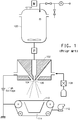
- Fig. 1 is a schematic of a prior art electroblowing apparatus useful for preparing a fibrous web according to the invention.
- the present invention relates to solvent-spun webs and fabrics for a variety of customer end-use applications, such as filtration media, energy storage separators, protective apparel and the like.
- the present invention uses an electroblowing process to spin a polymer dissolved in a high vapor pressure solvent at a high rate of throughput into fibers and webs.
- FIG. 1 is a schematic diagram of an electroblowing apparatus useful for carrying out the process of the present invention using electroblowing (or "electro-blown spinning") as described in International Publication Number WO2003/080905 .
- This prior art electroblowing method comprises feeding a solution of a polymer in a solvent from a storage tank 100, through a spinneret 102, to a spinning nozzle 104 to which a high voltage is applied, while compressed gas or blowing gas is directed toward the polymer solution through a blowing gas nozzle 106 as the polymer solution exits the spinning nozzle 104 to form fibers, and collecting the fibers into a web on a grounded collector 110 under vacuum created by vacuum chamber 114 and blower 112.
- the collection apparatus is preferably a moving collection belt positioned within the electrostatic field between the spinneret 102 and the collector 110. After being collected, the fiber layer is directed to and wound onto a wind-up roll on the downstream side of the collector 110.
- the fibrous web can be deposited onto any of a variety of porous scrim materials arranged on the moving collection belt, such as spunbonded nonwovens, meltblown nonwovens, needle punched nonwovens, woven fabrics, knit fabrics, apertured films, paper and combinations thereof.
- a secondary gas can contact the fibers downstream from the spinneret to help drive off solvent from the fiber.
- the secondary gas can be positioned to impinge the fibers or can be used as a sweeping gas to help remove solvent from the general spinning area.
- solvents with high vapor pressure can be used.
- solvents with vapor pressures of at least 6 kPa at 25°C are used, preferably of at least 10 kPa at 25°C and more preferably of at least 20 kPa at 25°C.
- Suitable solvents with high vapor pressure are the hydrocarbons pentane (68.3), hexane (20.2), heptane (6.1), cyclohexane (13), methylcyclohexane (6.1), and benzene (12.3), where the numbers in parentheses are the vapor pressures of these solvents at 25°C in units of kPa.
- the vapor pressure data was obtained from " Organic Solvents”. Volume 2, fourth edition, by John Riddick, William Bunger, and Theodore Sakano, John Wiley & Sons, 1986 or from the DIPPR® database of physical properties of solvents.
- the polymer solution can be spun at a temperature of about 0°C to the boiling point of the solvent.
- solvents can be used to prepare polymer solutions that can be spun at a discharge rate between 6 to 100 ml/min/hole, more advantageously between 10 to 100 ml/min/hole, and most advantageously between 20 to 100 ml/min/hole.
- the polymer(s) that can be used in making fiber layers in accordance with the process of the present invention are not particularly limited, provided that they are substantially soluble in the selected solvent at the desired concentration and can be spun into fibers by the process described herein.
- these polymers generally include hydrocarbon polymers.
- hydrocarbon polymers suitable for the present invention include polyolefins, polydienes, polystyrene and blends thereof.
- polyolefins include polyethylene, polypropylene, poly(1-butene), poly(4-methyl-1-pentene), and blends, mixtures and copolymers thereof.
- polysulfones examples include polycarbonates, poly(meth)acrylates, cellulose esters, polyvinylchlorides, and blends thereof.
- poly(meth)acrylates include polymethylacrylate and polymethylmethacrylate.
- cellulose esters include cellulose triacetate.
- polyesters include polyethylene therephthalate, polypropylene therephthalate, polybutylene therephthalate, poly(epsilon-caprolactone), poly(DL-lactic acid) and poly(L-lactide).
- the blowing gas can be selected from the group of air, nitrogen, argon, helium, carbon dioxide, hydrocarbons, halocarbons, halohydrocarbons and mixtures thereof.
- the blowing gas is injected at a flow velocity of 50 to 340 m/sec and a temperature from about ambient to 300°C.
- the fibers produced have a number average fiber diameter preferably less than 1,000 nanometers, more preferably less than 800 nanometers and most preferably less than 500 nanometers.
- the fibers can be continuous or discontinuous.
- the fibers can have an essentially round cross section shape.
- the electric field can have a voltage potential of about 10 to about 100 kV.
- the electric field can be used to create a corona charge.
- the fibers can be collected into a fibrous web comprising round cross section, weakly interacting polymer fibers having a number average fiber diameter less than about 1,000 nanometers.
- the secondary gas can be selected from the group of air, nitrogen, argon, helium, carbon dioxide, hydrocarbons, halocarbons, halohydrocarbons and mixtures thereof.
- the secondary gas is injected at a flow velocity of 50 to 340 m/sec and a temperature from about ambient to 300°C.
- Fiber Diameter was determined as follows. Two to three scanning electron microscope (SEM) images were taken of each fine fiber layer sample. The diameter of clearly distinguishable fine fibers were measured from the photographs and recorded. Defects were not included (i.e., lumps of fine fibers, polymer drops, intersections of fine fibers). The number average fiber diameter from about 50 to 300 counts for each sample was calculated.
- a 9 wt% solution of polymethylmethacrylate (PMMA) was dissolved in acetone (vapor pressure of 24.2 kPa at 25°C) at room temperature.
- a magnetic stirrer was used to agitate the solution.
- the homogeneous solution was transferred to a sealed glass container and transported to the spin chamber.
- the solution was transferred into the reservoir of the spin chamber and sealed.
- a spinneret with a 0.254 mm inside diameter single spinning nozzle was used.
- a drum collector was used to collect the sample.
- the spinneret was placed at a negative potential of 100 kV.
- the collector was grounded.
- the distance from the spinning nozzle exit to the collector surface was 51 cm. Air was used for the blowing gas.
- Nitrogen was used for the secondary gas to control the relative humidity and the temperature in the spin chamber.
- the flow of nitrogen was sufficient to avoid the concentration of the solvent vapor in the spin chamber exceeding the lower explosion limit.
- the relative humidity was controlled to be less than 11%.
- the spin chamber temperature was close to 23 °C for the duration of the experiment.
- a nitrogen pressure of 0.2044 MPa was used to maintain a solution flow rate of 6.7 ml/min/hole.
- the blowing gas was controlled to maintain an exit velocity on the order of 67 m/sec.
- the blowing gas temperature was close to 23 °C. Fiber was visible in the plume soon after the solution flow was initiated. Fiber was deposited in a swath on the drum. The number average fiber diameter of the fibers was measured to be 393 nanometers.
- a 9 wt% solution of polystyrene was dissolved in dichloromethane (vapor pressure of 58.1 kPa at 25°C) at room temperature.
- a magnetic stirrer was used to agitate the solution.
- the homogeneous solution was transferred to a sealed glass container and transported to the spin chamber.
- the solution was transferred into the reservoir of the spin chamber and sealed.
- a spinneret with a 0.406 mm inside diameter single spinning nozzle was used.
- a drum collector was used to collect the sample.
- the spinneret was placed at a negative potential of 100 kV.
- the collector was grounded.
- the distance from the spinning nozzle exit to the collector surface was 95 cm.
- Air was used for the blowing gas. Air was used for the secondary gas to control the relative humidity and the temperature in the spin chamber.
- the flow of air was sufficient to avoid the concentration of the solvent vapor in the spin chamber exceeding the lower explosion limit.
- the relative humidity was controlled to be less than 11%.
- the spin chamber temperature was close to 32 °C for the duration of the experiment.
- a nitrogen pressure of 0.515 MPa was used to maintain a solution flow rate of 34.3 ml/min/hole.
- the blowing gas was controlled to maintain an exit velocity on the order of 150 m/sec.
- the blowing gas temperature was close to 24 °C. Fiber was visible in the plume soon after the solution flow was initiated. Fiber was deposited in a swath on the drum. The number average fiber diameter of the fibers was measured to be 335 nanometers.
- a 9 wt% solution of polystyrene was dissolved in dichloromethane (vapor pressure of 58.1 kPa at 25°C) at room temperature.
- a magnetic stirrer was used to agitate the solution.
- the homogeneous solution was transferred to a sealed glass container and transported to the spin chamber.
- the solution was transferred into the reservoir of the spin chamber and sealed.
- a spinneret with a 0.406 mm inside diameter single spinning nozzle was used.
- a drum collector was used to collect the sample.
- the spinneret was placed at a negative potential of 100 kV.
- the collector was grounded.
- the distance from the spinning nozzle exit to the collector surface was 114 cm.
- Air was used for the blowing gas. Air was used for the secondary gas to control the relative humidity and the temperature in the spin chamber.
- the flow of air was sufficient to avoid the concentration of the solvent vapor in the spin chamber exceeding the lower explosion limit.
- the relative humidity was controlled to be less than 11 %.
- the spin chamber temperature was close to 37 °C for the duration of the experiment.
- a nitrogen pressure of 0.77 MPa was used to maintain a solution flow rate of 57.1 ml/min/hole.
- the blowing gas was controlled to maintain an exit velocity on the order of 150 m/sec.
- the blowing gas temperature was close to 24 °C. Fiber was visible in the plume soon after the solution flow was initiated. Fiber was deposited in a swath on the drum. The number average fiber diameter of the fibers was measured to be 630 nanometers.
- Engage 8400 an ethylene octene copolymer
- methylcyclohexane vapor pressure of 6.1 kPa at 25°C
- a magnetic stirrer was used to agitate the hot solution.
- the homogeneous solution was transferred to a sealed glass container and transported to the spin chamber.
- the solution was transferred into the reservoir of the spin chamber and sealed.
- a spinneret with a 0.4064 mm inside diameter single spinning nozzle was used.
- a drum collector was used to collect the sample.
- the spinneret was placed at a negative potential of 100 kV.
- the collector was grounded. The distance from the spinning nozzle exit to the collector surface was 30 cm.
- Air was used for the blowing gas.
- Nitrogen was used for the secondary gas to control the relative humidity and the temperature in the spin chamber. The flow of nitrogen was sufficient to avoid the concentration of the solvent vapor in the spin chamber exceeding the lower explosion limit. The relative humidity was controlled to be less than 9%.
- the spin chamber temperature was close to 29 °C for the duration of the experiment.
- a nitrogen pressure of 0.308 MPa was used to maintain a solution flow rate of 12.6 ml/min/hole.
- the blowing gas was controlled to maintain an exit velocity on the order of 156 m/sec.
- the blowing gas temperature was close to 28 °C.
Description
- The present invention relates to a process for forming a fibrous web from a high throughput electroblowing process.
- Solution spinning processes are frequently used to manufacture fibers and nonwoven fabrics, and in some cases have the advantage of high throughputs, such that the fibers or fabrics can be made in large, commercially viable quantities. These processes can be used to make fibrous webs that are useful in medical garments, filters and other end uses that require a selective barrier. The performance of these types of fibrous webs can be enhanced with the utilization of fibers with small diameters.
- A type of solution spinning called electroblowing produces very fine fibers by spinning a polymer solution through a spinning nozzle in combination with a blowing gas and in the presence of an electric field.
- However, it would be desirable to increase the throughput of this process to increase process efficiencies and lower the cost of manufacturing, without sacrificing fiber uniformity and product quality.
-
WO 2007/022390 A1 describes a fiber spinning process using an electrically conductive polymer-containing liquid stream wherein the liquid stream is either a polymer solution or a molten polymer. - The present invention is a fiber spinning process comprising the steps of providing a polymer solution, which comprises at least one polymer dissolved in at least one solvent with a vapor pressure of at least about 6 kPa at 25°C, to a spinneret, issuing the polymer solution in combination with a blowing gas in a direction away from at least one spinning nozzle in the spinneret and in the presence of an electric field wherein the polymer solution is discharged through the spinning nozzle at a discharge rate between about 6 to about 100 ml/min/hole, forming fibers, and collecting the fibers on a collector, wherein the solvent is selected from the group consisting of pentane, hexane, heptane, cyclohexane, methylcyclohexane, and benzene.
- The accompanying drawing, which is incorporated in and constitutes a part of this specification, and together with the description, serves to explain the principles of the invention.
-
Fig. 1 is a schematic of a prior art electroblowing apparatus useful for preparing a fibrous web according to the invention. - The present invention relates to solvent-spun webs and fabrics for a variety of customer end-use applications, such as filtration media, energy storage separators, protective apparel and the like.
- The present invention uses an electroblowing process to spin a polymer dissolved in a high vapor pressure solvent at a high rate of throughput into fibers and webs.
- The process for making a fiber layer(s) is disclosed in International Publication Number
WO2003/080905 (U.S. Serial No. 10/822,325 Fig. 1 is a schematic diagram of an electroblowing apparatus useful for carrying out the process of the present invention using electroblowing (or "electro-blown spinning") as described in International Publication NumberWO2003/080905 . This prior art electroblowing method comprises feeding a solution of a polymer in a solvent from astorage tank 100, through a spinneret 102, to a spinningnozzle 104 to which a high voltage is applied, while compressed gas or blowing gas is directed toward the polymer solution through a blowinggas nozzle 106 as the polymer solution exits the spinningnozzle 104 to form fibers, and collecting the fibers into a web on agrounded collector 110 under vacuum created byvacuum chamber 114 andblower 112. - The collection apparatus is preferably a moving collection belt positioned within the electrostatic field between the spinneret 102 and the
collector 110. After being collected, the fiber layer is directed to and wound onto a wind-up roll on the downstream side of thecollector 110. Optionally, the fibrous web can be deposited onto any of a variety of porous scrim materials arranged on the moving collection belt, such as spunbonded nonwovens, meltblown nonwovens, needle punched nonwovens, woven fabrics, knit fabrics, apertured films, paper and combinations thereof. - Optionally, a secondary gas can contact the fibers downstream from the spinneret to help drive off solvent from the fiber. When electroblowing fibers with a high throughput rate, large quantities of solvent must be removed from the fiber forming polymer solution. The secondary gas can be positioned to impinge the fibers or can be used as a sweeping gas to help remove solvent from the general spinning area.
- In order to spin fibers at high throughput or discharge rate, solvents with high vapor pressure can be used. According to the invention, solvents with vapor pressures of at least 6 kPa at 25°C are used, preferably of at least 10 kPa at 25°C and more preferably of at least 20 kPa at 25°C. Suitable solvents with high vapor pressure are the hydrocarbons pentane (68.3), hexane (20.2), heptane (6.1), cyclohexane (13), methylcyclohexane (6.1), and benzene (12.3), where the numbers in parentheses are the vapor pressures of these solvents at 25°C in units of kPa. The vapor pressure data was obtained from "Organic Solvents". Volume 2, fourth edition, by John Riddick, William Bunger, and Theodore Sakano, John Wiley & Sons, 1986 or from the DIPPR® database of physical properties of solvents.
- The polymer solution can be spun at a temperature of about 0°C to the boiling point of the solvent.
- These solvents can be used to prepare polymer solutions that can be spun at a discharge rate between 6 to 100 ml/min/hole, more advantageously between 10 to 100 ml/min/hole, and most advantageously between 20 to 100 ml/min/hole.
- The polymer(s) that can be used in making fiber layers in accordance with the process of the present invention are not particularly limited, provided that they are substantially soluble in the selected solvent at the desired concentration and can be spun into fibers by the process described herein. Examples of these polymers generally include hydrocarbon polymers. Examples of hydrocarbon polymers suitable for the present invention include polyolefins, polydienes, polystyrene and blends thereof. Examples polyolefins include polyethylene, polypropylene, poly(1-butene), poly(4-methyl-1-pentene), and blends, mixtures and copolymers thereof.
- In addition to the forgoing polymers, other examples include polysulfones, polycarbonates, poly(meth)acrylates, cellulose esters, polyvinylchlorides, and blends thereof. Examples of poly(meth)acrylates include polymethylacrylate and polymethylmethacrylate. Examples of cellulose esters include cellulose triacetate. Examples of polyesters include polyethylene therephthalate, polypropylene therephthalate, polybutylene therephthalate, poly(epsilon-caprolactone), poly(DL-lactic acid) and poly(L-lactide).
- The blowing gas can be selected from the group of air, nitrogen, argon, helium, carbon dioxide, hydrocarbons, halocarbons, halohydrocarbons and mixtures thereof. The blowing gas is injected at a flow velocity of 50 to 340 m/sec and a temperature from about ambient to 300°C.
- The fibers produced have a number average fiber diameter preferably less than 1,000 nanometers, more preferably less than 800 nanometers and most preferably less than 500 nanometers. The fibers can be continuous or discontinuous. The fibers can have an essentially round cross section shape.
- The electric field can have a voltage potential of about 10 to about 100 kV. The electric field can be used to create a corona charge.
- The fibers can be collected into a fibrous web comprising round cross section, weakly interacting polymer fibers having a number average fiber diameter less than about 1,000 nanometers.
- The secondary gas can be selected from the group of air, nitrogen, argon, helium, carbon dioxide, hydrocarbons, halocarbons, halohydrocarbons and mixtures thereof. The secondary gas is injected at a flow velocity of 50 to 340 m/sec and a temperature from about ambient to 300°C.
- Fiber Diameter was determined as follows. Two to three scanning electron microscope (SEM) images were taken of each fine fiber layer sample. The diameter of clearly distinguishable fine fibers were measured from the photographs and recorded. Defects were not included (i.e., lumps of fine fibers, polymer drops, intersections of fine fibers). The number average fiber diameter from about 50 to 300 counts for each sample was calculated.
- The fiber examples below were prepared using the general process and apparatus described above with the specific changes as noted below.
- A 9 wt% solution of polymethylmethacrylate (PMMA) was dissolved in acetone (vapor pressure of 24.2 kPa at 25°C) at room temperature. A magnetic stirrer was used to agitate the solution. The homogeneous solution was transferred to a sealed glass container and transported to the spin chamber. The solution was transferred into the reservoir of the spin chamber and sealed. A spinneret with a 0.254 mm inside diameter single spinning nozzle was used. A drum collector was used to collect the sample. The spinneret was placed at a negative potential of 100 kV. The collector was grounded. The distance from the spinning nozzle exit to the collector surface was 51 cm. Air was used for the blowing gas. Nitrogen was used for the secondary gas to control the relative humidity and the temperature in the spin chamber. The flow of nitrogen was sufficient to avoid the concentration of the solvent vapor in the spin chamber exceeding the lower explosion limit. The relative humidity was controlled to be less than 11%. The spin chamber temperature was close to 23 °C for the duration of the experiment. A nitrogen pressure of 0.2044 MPa was used to maintain a solution flow rate of 6.7 ml/min/hole. The blowing gas was controlled to maintain an exit velocity on the order of 67 m/sec. The blowing gas temperature was close to 23 °C. Fiber was visible in the plume soon after the solution flow was initiated. Fiber was deposited in a swath on the drum. The number average fiber diameter of the fibers was measured to be 393 nanometers.
- A 9 wt% solution of polystyrene was dissolved in dichloromethane (vapor pressure of 58.1 kPa at 25°C) at room temperature. A magnetic stirrer was used to agitate the solution. The homogeneous solution was transferred to a sealed glass container and transported to the spin chamber. The solution was transferred into the reservoir of the spin chamber and sealed. A spinneret with a 0.406 mm inside diameter single spinning nozzle was used. A drum collector was used to collect the sample. The spinneret was placed at a negative potential of 100 kV. The collector was grounded. The distance from the spinning nozzle exit to the collector surface was 95 cm. Air was used for the blowing gas. Air was used for the secondary gas to control the relative humidity and the temperature in the spin chamber. The flow of air was sufficient to avoid the concentration of the solvent vapor in the spin chamber exceeding the lower explosion limit. The relative humidity was controlled to be less than 11%. The spin chamber temperature was close to 32 °C for the duration of the experiment. A nitrogen pressure of 0.515 MPa was used to maintain a solution flow rate of 34.3 ml/min/hole. The blowing gas was controlled to maintain an exit velocity on the order of 150 m/sec. The blowing gas temperature was close to 24 °C. Fiber was visible in the plume soon after the solution flow was initiated. Fiber was deposited in a swath on the drum. The number average fiber diameter of the fibers was measured to be 335 nanometers.
- A 9 wt% solution of polystyrene was dissolved in dichloromethane (vapor pressure of 58.1 kPa at 25°C) at room temperature. A magnetic stirrer was used to agitate the solution. The homogeneous solution was transferred to a sealed glass container and transported to the spin chamber. The solution was transferred into the reservoir of the spin chamber and sealed. A spinneret with a 0.406 mm inside diameter single spinning nozzle was used. A drum collector was used to collect the sample. The spinneret was placed at a negative potential of 100 kV. The collector was grounded. The distance from the spinning nozzle exit to the collector surface was 114 cm. Air was used for the blowing gas. Air was used for the secondary gas to control the relative humidity and the temperature in the spin chamber. The flow of air was sufficient to avoid the concentration of the solvent vapor in the spin chamber exceeding the lower explosion limit. The relative humidity was controlled to be less than 11 %. The spin chamber temperature was close to 37 °C for the duration of the experiment. A nitrogen pressure of 0.77 MPa was used to maintain a solution flow rate of 57.1 ml/min/hole. The blowing gas was controlled to maintain an exit velocity on the order of 150 m/sec. The blowing gas temperature was close to 24 °C. Fiber was visible in the plume soon after the solution flow was initiated. Fiber was deposited in a swath on the drum. The number average fiber diameter of the fibers was measured to be 630 nanometers.
- An 11 wt% solution of Engage 8400 (an ethylene octene copolymer), available from DuPont, was dissolved in methylcyclohexane (vapor pressure of 6.1 kPa at 25°C) using a reflux condenser. A magnetic stirrer was used to agitate the hot solution. The homogeneous solution was transferred to a sealed glass container and transported to the spin chamber. The solution was transferred into the reservoir of the spin chamber and sealed. A spinneret with a 0.4064 mm inside diameter single spinning nozzle was used. A drum collector was used to collect the sample. The spinneret was placed at a negative potential of 100 kV. The collector was grounded. The distance from the spinning nozzle exit to the collector surface was 30 cm. Air was used for the blowing gas. Nitrogen was used for the secondary gas to control the relative humidity and the temperature in the spin chamber. The flow of nitrogen was sufficient to avoid the concentration of the solvent vapor in the spin chamber exceeding the lower explosion limit. The relative humidity was controlled to be less than 9%. The spin chamber temperature was close to 29 °C for the duration of the experiment. A nitrogen pressure of 0.308 MPa was used to maintain a solution flow rate of 12.6 ml/min/hole. The blowing gas was controlled to maintain an exit velocity on the order of 156 m/sec. The blowing gas temperature was close to 28 °C. Once the solution flow was initiated, fiber was visible in the plume. Fiber was deposited in a swath on the drum. The number average fiber diameter of the fibers was measured to be 502 nanometers.
Claims (13)
- A fiber spinning process comprising:providing a polymer solution, which comprises at least one polymer dissolved in at least one solvent with a vapor pressure of at least 6 kPa at 25°C, to a spinneret;issuing the polymer solution in combination with a blowing gas in a direction away from at least one spinning nozzle in the spinneret and in the presence of an electric field wherein the polymer solution is discharged through the spinning nozzle at a discharge rate between 6 to 100 ml/min/hole;forming fibers; andcollecting the fibers on a collector,wherein the solvent is selected from the group consisting of pentane, hexane, heptane, cyclohexane, methylcyclohexane, and benzene.
- The process according to claim 1, wherein the vapor pressure is of at least 10 kPa at 25°C, or preferably of at least 20 kPa at 25°C.
- The process according to claim 1, wherein the polymer solution is discharged through the spinning nozzle at a discharge rate between 10 to 100 ml/min/hole, or preferably between 20 to 100 ml/min/hole.
- The process according to claim 1, wherein the blowing gas is selected from the group of air, nitrogen, argon, helium, carbon dioxide, hydrocarbons, halocarbons, halohydrocarbons and mixtures thereof.
- The process according to claim 1, wherein the blowing gas is injected at a flow velocity of 50 to 340 m/sec and a temperature from ambient to 300°C.
- The process according to claim 1, wherein the fibers have a number average fiber diameter less than 1000 nanometers, preferably less than 800 nanometers, more preferably less than 500 nanometers.
- The process according to claim 1, wherein the electric field has a voltage potential of 10 kV to 100 kV.
- The process according to claim 1, wherein the electrical field is a corona charging field.
- The process according to claim 1, wherein the fibers have a cross section shape that is essentially round.
- The process according to claim 1, further comprising contacting the fibers with a secondary gas located downstream from the spinneret.
- The process according to claim 10, wherein the blowing gas is selected from the group of air, nitrogen, argon, helium, carbon dioxide, hydrocarbons, halocarbons, halohydrocarbons and mixtures thereof.
- The process according to claim 10, wherein the blowing gas is injected at a flow velocity of about 50 to about 340 m/sec and a temperature from about ambient to about 300°C.
- The process according to claim 1, wherein said at least one polymer in said polymer solution is selected from the group consisting of polyolefins, polydienes, polystyrene, polysulfones, polycarbonates, poly(meth)acrylates, cellulose esters, polyvinylchlorides and blends thereof.
Priority Applications (1)
| Application Number | Priority Date | Filing Date | Title |
|---|---|---|---|
| EP18206666.2A EP3470556B1 (en) | 2008-09-05 | 2009-09-08 | High throughput electroblowing process |
Applications Claiming Priority (2)
| Application Number | Priority Date | Filing Date | Title |
|---|---|---|---|
| US19110208P | 2008-09-05 | 2008-09-05 | |
| PCT/US2009/056157 WO2010028326A1 (en) | 2008-09-05 | 2009-09-08 | High throughput electroblowing process |
Related Child Applications (1)
| Application Number | Title | Priority Date | Filing Date |
|---|---|---|---|
| EP18206666.2A Division EP3470556B1 (en) | 2008-09-05 | 2009-09-08 | High throughput electroblowing process |
Publications (2)
| Publication Number | Publication Date |
|---|---|
| EP2321451A1 EP2321451A1 (en) | 2011-05-18 |
| EP2321451B1 true EP2321451B1 (en) | 2018-12-19 |
Family
ID=41343361
Family Applications (2)
| Application Number | Title | Priority Date | Filing Date |
|---|---|---|---|
| EP18206666.2A Active EP3470556B1 (en) | 2008-09-05 | 2009-09-08 | High throughput electroblowing process |
| EP09792294.2A Active EP2321451B1 (en) | 2008-09-05 | 2009-09-08 | High throughput electroblowing process |
Family Applications Before (1)
| Application Number | Title | Priority Date | Filing Date |
|---|---|---|---|
| EP18206666.2A Active EP3470556B1 (en) | 2008-09-05 | 2009-09-08 | High throughput electroblowing process |
Country Status (7)
| Country | Link |
|---|---|
| US (1) | US20100059906A1 (en) |
| EP (2) | EP3470556B1 (en) |
| JP (1) | JP5480903B2 (en) |
| KR (1) | KR20110050557A (en) |
| CN (1) | CN102144054A (en) |
| BR (1) | BRPI0913530A2 (en) |
| WO (1) | WO2010028326A1 (en) |
Families Citing this family (9)
| Publication number | Priority date | Publication date | Assignee | Title |
|---|---|---|---|---|
| CN102115025B (en) * | 2011-01-07 | 2012-12-26 | 山东理工大学 | Method for preparing polystyrene micro-sphere micro-array by ultrasonic focusing micro-jet process |
| CN102121173B (en) * | 2011-02-22 | 2012-05-30 | 天津工业大学 | Method for preparing sound-absorbing and heat-insulating materials formed by superfine fiber nonwovens |
| CN102071542B (en) * | 2011-02-22 | 2012-08-29 | 天津工业大学 | Method for preparing polymeric nano-micro fiber non-woven fabric |
| JP2016053232A (en) * | 2014-09-04 | 2016-04-14 | 富士フイルム株式会社 | Nano fiber production method |
| CN104372422A (en) * | 2014-11-07 | 2015-02-25 | 江西先材纳米纤维科技有限公司 | Device and method for quickly manufacturing fluffy polymer nano-fibers |
| KR102466378B1 (en) | 2017-10-30 | 2022-11-11 | 주식회사 엘지화학 | Super absorbent polymer non-woven fabric fiber and a method for preparing the same |
| KR102099662B1 (en) * | 2017-11-09 | 2020-04-13 | 단국대학교 천안캠퍼스 산학협력단 | Method for preparing fibrous scaffolds for patient-tuned tissue engineering |
| KR102548151B1 (en) * | 2021-09-23 | 2023-06-28 | 한국과학기술원 | Electrospinning composition and biodegradable filter membrane using the same |
| CN116815335B (en) * | 2023-08-30 | 2023-11-24 | 江苏青昀新材料有限公司 | Metal film energy accumulator for storing flash spinning solution and flash spinning system |
Family Cites Families (19)
| Publication number | Priority date | Publication date | Assignee | Title |
|---|---|---|---|---|
| GB1522605A (en) * | 1974-09-26 | 1978-08-23 | Ici Ltd | Preparation of fibrous sheet product |
| JPH03220305A (en) * | 1989-11-21 | 1991-09-27 | I C I Japan Kk | Production of antistatic spun yarn |
| US6183670B1 (en) * | 1997-09-23 | 2001-02-06 | Leonard Torobin | Method and apparatus for producing high efficiency fibrous media incorporating discontinuous sub-micron diameter fibers, and web media formed thereby |
| US6713011B2 (en) * | 2001-05-16 | 2004-03-30 | The Research Foundation At State University Of New York | Apparatus and methods for electrospinning polymeric fibers and membranes |
| US6520425B1 (en) * | 2001-08-21 | 2003-02-18 | The University Of Akron | Process and apparatus for the production of nanofibers |
| KR100549140B1 (en) * | 2002-03-26 | 2006-02-03 | 이 아이 듀폰 디 네모아 앤드 캄파니 | A electro-blown spinning process of preparing for the nanofiber web |
| US20030215624A1 (en) * | 2002-04-05 | 2003-11-20 | Layman John M. | Electrospinning of vinyl alcohol polymer and copolymer fibers |
| KR100491228B1 (en) * | 2003-02-24 | 2005-05-24 | 김학용 | A process of preparing continuous filament composed of nano fiber |
| HUE033054T2 (en) * | 2003-03-07 | 2017-11-28 | Univ Virginia Commonwealth | Electroprocessed phenolic materials and methods |
| EP1709219A4 (en) * | 2003-09-05 | 2008-03-05 | Univ Louisiana State | Nanofibers, and apparatus and methods for fabricating nanofibers by reactive electrospinning |
| US7662332B2 (en) * | 2003-10-01 | 2010-02-16 | The Research Foundation Of State University Of New York | Electro-blowing technology for fabrication of fibrous articles and its applications of hyaluronan |
| US20060012084A1 (en) * | 2004-07-13 | 2006-01-19 | Armantrout Jack E | Electroblowing web formation process |
| US7887311B2 (en) * | 2004-09-09 | 2011-02-15 | The Research Foundation Of State University Of New York | Apparatus and method for electro-blowing or blowing-assisted electro-spinning technology |
| JP2008515668A (en) * | 2004-10-06 | 2008-05-15 | ザ リサーチ ファウンデーション オブ ステイト ユニバーシティー オブ ニューヨーク | High flow rate and low adhesion filtration media |
| US7846374B2 (en) * | 2004-11-05 | 2010-12-07 | E. I. Du Pont De Nemours And Company | Blowing gases in electroblowing process |
| US20060135020A1 (en) * | 2004-12-17 | 2006-06-22 | Weinberg Mark G | Flash spun web containing sub-micron filaments and process for forming same |
| US8808608B2 (en) * | 2004-12-27 | 2014-08-19 | E I Du Pont De Nemours And Company | Electroblowing web formation process |
| US7582247B2 (en) * | 2005-08-17 | 2009-09-01 | E. I. Du Pont De Nemours And Company | Electroblowing fiber spinning process |
| US8211353B2 (en) * | 2008-09-05 | 2012-07-03 | E. I. Du Pont De Nemours And Company | Fiber spinning process using a weakly interacting polymer |
-
2009
- 2009-09-03 US US12/553,603 patent/US20100059906A1/en not_active Abandoned
- 2009-09-08 KR KR1020117007758A patent/KR20110050557A/en not_active Application Discontinuation
- 2009-09-08 JP JP2011526256A patent/JP5480903B2/en active Active
- 2009-09-08 EP EP18206666.2A patent/EP3470556B1/en active Active
- 2009-09-08 EP EP09792294.2A patent/EP2321451B1/en active Active
- 2009-09-08 WO PCT/US2009/056157 patent/WO2010028326A1/en active Application Filing
- 2009-09-08 BR BRPI0913530A patent/BRPI0913530A2/en not_active IP Right Cessation
- 2009-09-08 CN CN200980134737XA patent/CN102144054A/en active Pending
Also Published As
| Publication number | Publication date |
|---|---|
| EP3470556B1 (en) | 2020-06-10 |
| EP3470556A1 (en) | 2019-04-17 |
| KR20110050557A (en) | 2011-05-13 |
| JP2012502197A (en) | 2012-01-26 |
| WO2010028326A1 (en) | 2010-03-11 |
| JP5480903B2 (en) | 2014-04-23 |
| CN102144054A (en) | 2011-08-03 |
| BRPI0913530A2 (en) | 2019-09-24 |
| EP2321451A1 (en) | 2011-05-18 |
| US20100059906A1 (en) | 2010-03-11 |
Similar Documents
| Publication | Publication Date | Title |
|---|---|---|
| EP2321451B1 (en) | High throughput electroblowing process | |
| JP5480904B2 (en) | Fiber spinning using weakly interacting polymers | |
| JP4076556B2 (en) | Nonwoven fabric and method for producing the same | |
| KR101519169B1 (en) | Production of nanofibers by melt spinning | |
| Zhang et al. | Design of ultra-fine nonwovens via electrospinning of Nylon 6: Spinning parameters and filtration efficiency | |
| Nayak et al. | Melt-electrospinning of nanofibers | |
| JP5483878B2 (en) | Filter media for liquid filtration | |
| KR101730663B1 (en) | Non-Woven Polymeric Webs | |
| BRPI0617575A2 (en) | coalescent filtration media and process of removing liquid, oil and / or water aerosols from a gas stream | |
| EP3060326A1 (en) | Electret nanofibrous web as air filtration media | |
| US10208408B2 (en) | Method for manufacturing ultrafine fiber | |
| JP2010185153A (en) | Method for producing extra fine fiber non-woven fabric, and apparatus for producing the same | |
| Tipper et al. | Developments in the use of nanofibres in nonwovens | |
| Nayak et al. | RMIT University, Melbourne, VIC, Australia |
Legal Events
| Date | Code | Title | Description |
|---|---|---|---|
| PUAI | Public reference made under article 153(3) epc to a published international application that has entered the european phase |
Free format text: ORIGINAL CODE: 0009012 |
|
| 17P | Request for examination filed |
Effective date: 20110209 |
|
| AK | Designated contracting states |
Kind code of ref document: A1 Designated state(s): AT BE BG CH CY CZ DE DK EE ES FI FR GB GR HR HU IE IS IT LI LT LU LV MC MK MT NL NO PL PT RO SE SI SK SM TR |
|
| AX | Request for extension of the european patent |
Extension state: AL BA RS |
|
| DAX | Request for extension of the european patent (deleted) | ||
| 17Q | First examination report despatched |
Effective date: 20161010 |
|
| STAA | Information on the status of an ep patent application or granted ep patent |
Free format text: STATUS: EXAMINATION IS IN PROGRESS |
|
| GRAP | Despatch of communication of intention to grant a patent |
Free format text: ORIGINAL CODE: EPIDOSNIGR1 |
|
| STAA | Information on the status of an ep patent application or granted ep patent |
Free format text: STATUS: GRANT OF PATENT IS INTENDED |
|
| INTG | Intention to grant announced |
Effective date: 20180627 |
|
| GRAS | Grant fee paid |
Free format text: ORIGINAL CODE: EPIDOSNIGR3 |
|
| GRAA | (expected) grant |
Free format text: ORIGINAL CODE: 0009210 |
|
| STAA | Information on the status of an ep patent application or granted ep patent |
Free format text: STATUS: THE PATENT HAS BEEN GRANTED |
|
| AK | Designated contracting states |
Kind code of ref document: B1 Designated state(s): AT BE BG CH CY CZ DE DK EE ES FI FR GB GR HR HU IE IS IT LI LT LU LV MC MK MT NL NO PL PT RO SE SI SK SM TR |
|
| REG | Reference to a national code |
Ref country code: GB Ref legal event code: FG4D |
|
| REG | Reference to a national code |
Ref country code: CH Ref legal event code: EP |
|
| RAP2 | Party data changed (patent owner data changed or rights of a patent transferred) |
Owner name: E. I. DU PONT DE NEMOURS AND COMPANY |
|
| REG | Reference to a national code |
Ref country code: IE Ref legal event code: FG4D |
|
| REG | Reference to a national code |
Ref country code: DE Ref legal event code: R096 Ref document number: 602009056311 Country of ref document: DE |
|
| REG | Reference to a national code |
Ref country code: AT Ref legal event code: REF Ref document number: 1078820 Country of ref document: AT Kind code of ref document: T Effective date: 20190115 |
|
| REG | Reference to a national code |
Ref country code: NL Ref legal event code: MP Effective date: 20181219 |
|
| PG25 | Lapsed in a contracting state [announced via postgrant information from national office to epo] |
Ref country code: LV Free format text: LAPSE BECAUSE OF FAILURE TO SUBMIT A TRANSLATION OF THE DESCRIPTION OR TO PAY THE FEE WITHIN THE PRESCRIBED TIME-LIMIT Effective date: 20181219 Ref country code: HR Free format text: LAPSE BECAUSE OF FAILURE TO SUBMIT A TRANSLATION OF THE DESCRIPTION OR TO PAY THE FEE WITHIN THE PRESCRIBED TIME-LIMIT Effective date: 20181219 Ref country code: FI Free format text: LAPSE BECAUSE OF FAILURE TO SUBMIT A TRANSLATION OF THE DESCRIPTION OR TO PAY THE FEE WITHIN THE PRESCRIBED TIME-LIMIT Effective date: 20181219 Ref country code: BG Free format text: LAPSE BECAUSE OF FAILURE TO SUBMIT A TRANSLATION OF THE DESCRIPTION OR TO PAY THE FEE WITHIN THE PRESCRIBED TIME-LIMIT Effective date: 20190319 Ref country code: NO Free format text: LAPSE BECAUSE OF FAILURE TO SUBMIT A TRANSLATION OF THE DESCRIPTION OR TO PAY THE FEE WITHIN THE PRESCRIBED TIME-LIMIT Effective date: 20190319 Ref country code: LT Free format text: LAPSE BECAUSE OF FAILURE TO SUBMIT A TRANSLATION OF THE DESCRIPTION OR TO PAY THE FEE WITHIN THE PRESCRIBED TIME-LIMIT Effective date: 20181219 |
|
| REG | Reference to a national code |
Ref country code: LT Ref legal event code: MG4D |
|
| REG | Reference to a national code |
Ref country code: AT Ref legal event code: MK05 Ref document number: 1078820 Country of ref document: AT Kind code of ref document: T Effective date: 20181219 |
|
| PG25 | Lapsed in a contracting state [announced via postgrant information from national office to epo] |
Ref country code: GR Free format text: LAPSE BECAUSE OF FAILURE TO SUBMIT A TRANSLATION OF THE DESCRIPTION OR TO PAY THE FEE WITHIN THE PRESCRIBED TIME-LIMIT Effective date: 20190320 Ref country code: SE Free format text: LAPSE BECAUSE OF FAILURE TO SUBMIT A TRANSLATION OF THE DESCRIPTION OR TO PAY THE FEE WITHIN THE PRESCRIBED TIME-LIMIT Effective date: 20181219 |
|
| PG25 | Lapsed in a contracting state [announced via postgrant information from national office to epo] |
Ref country code: NL Free format text: LAPSE BECAUSE OF FAILURE TO SUBMIT A TRANSLATION OF THE DESCRIPTION OR TO PAY THE FEE WITHIN THE PRESCRIBED TIME-LIMIT Effective date: 20181219 |
|
| PG25 | Lapsed in a contracting state [announced via postgrant information from national office to epo] |
Ref country code: PL Free format text: LAPSE BECAUSE OF FAILURE TO SUBMIT A TRANSLATION OF THE DESCRIPTION OR TO PAY THE FEE WITHIN THE PRESCRIBED TIME-LIMIT Effective date: 20181219 Ref country code: PT Free format text: LAPSE BECAUSE OF FAILURE TO SUBMIT A TRANSLATION OF THE DESCRIPTION OR TO PAY THE FEE WITHIN THE PRESCRIBED TIME-LIMIT Effective date: 20190419 Ref country code: CZ Free format text: LAPSE BECAUSE OF FAILURE TO SUBMIT A TRANSLATION OF THE DESCRIPTION OR TO PAY THE FEE WITHIN THE PRESCRIBED TIME-LIMIT Effective date: 20181219 Ref country code: ES Free format text: LAPSE BECAUSE OF FAILURE TO SUBMIT A TRANSLATION OF THE DESCRIPTION OR TO PAY THE FEE WITHIN THE PRESCRIBED TIME-LIMIT Effective date: 20181219 Ref country code: IT Free format text: LAPSE BECAUSE OF FAILURE TO SUBMIT A TRANSLATION OF THE DESCRIPTION OR TO PAY THE FEE WITHIN THE PRESCRIBED TIME-LIMIT Effective date: 20181219 |
|
| PG25 | Lapsed in a contracting state [announced via postgrant information from national office to epo] |
Ref country code: RO Free format text: LAPSE BECAUSE OF FAILURE TO SUBMIT A TRANSLATION OF THE DESCRIPTION OR TO PAY THE FEE WITHIN THE PRESCRIBED TIME-LIMIT Effective date: 20181219 Ref country code: SK Free format text: LAPSE BECAUSE OF FAILURE TO SUBMIT A TRANSLATION OF THE DESCRIPTION OR TO PAY THE FEE WITHIN THE PRESCRIBED TIME-LIMIT Effective date: 20181219 Ref country code: SM Free format text: LAPSE BECAUSE OF FAILURE TO SUBMIT A TRANSLATION OF THE DESCRIPTION OR TO PAY THE FEE WITHIN THE PRESCRIBED TIME-LIMIT Effective date: 20181219 Ref country code: EE Free format text: LAPSE BECAUSE OF FAILURE TO SUBMIT A TRANSLATION OF THE DESCRIPTION OR TO PAY THE FEE WITHIN THE PRESCRIBED TIME-LIMIT Effective date: 20181219 Ref country code: IS Free format text: LAPSE BECAUSE OF FAILURE TO SUBMIT A TRANSLATION OF THE DESCRIPTION OR TO PAY THE FEE WITHIN THE PRESCRIBED TIME-LIMIT Effective date: 20190419 |
|
| REG | Reference to a national code |
Ref country code: DE Ref legal event code: R097 Ref document number: 602009056311 Country of ref document: DE |
|
| PLBE | No opposition filed within time limit |
Free format text: ORIGINAL CODE: 0009261 |
|
| STAA | Information on the status of an ep patent application or granted ep patent |
Free format text: STATUS: NO OPPOSITION FILED WITHIN TIME LIMIT |
|
| PG25 | Lapsed in a contracting state [announced via postgrant information from national office to epo] |
Ref country code: DK Free format text: LAPSE BECAUSE OF FAILURE TO SUBMIT A TRANSLATION OF THE DESCRIPTION OR TO PAY THE FEE WITHIN THE PRESCRIBED TIME-LIMIT Effective date: 20181219 Ref country code: AT Free format text: LAPSE BECAUSE OF FAILURE TO SUBMIT A TRANSLATION OF THE DESCRIPTION OR TO PAY THE FEE WITHIN THE PRESCRIBED TIME-LIMIT Effective date: 20181219 |
|
| 26N | No opposition filed |
Effective date: 20190920 |
|
| PG25 | Lapsed in a contracting state [announced via postgrant information from national office to epo] |
Ref country code: SI Free format text: LAPSE BECAUSE OF FAILURE TO SUBMIT A TRANSLATION OF THE DESCRIPTION OR TO PAY THE FEE WITHIN THE PRESCRIBED TIME-LIMIT Effective date: 20181219 |
|
| PG25 | Lapsed in a contracting state [announced via postgrant information from national office to epo] |
Ref country code: TR Free format text: LAPSE BECAUSE OF FAILURE TO SUBMIT A TRANSLATION OF THE DESCRIPTION OR TO PAY THE FEE WITHIN THE PRESCRIBED TIME-LIMIT Effective date: 20181219 |
|
| PG25 | Lapsed in a contracting state [announced via postgrant information from national office to epo] |
Ref country code: MC Free format text: LAPSE BECAUSE OF FAILURE TO SUBMIT A TRANSLATION OF THE DESCRIPTION OR TO PAY THE FEE WITHIN THE PRESCRIBED TIME-LIMIT Effective date: 20181219 |
|
| REG | Reference to a national code |
Ref country code: CH Ref legal event code: PL |
|
| PG25 | Lapsed in a contracting state [announced via postgrant information from national office to epo] |
Ref country code: LI Free format text: LAPSE BECAUSE OF NON-PAYMENT OF DUE FEES Effective date: 20190930 Ref country code: LU Free format text: LAPSE BECAUSE OF NON-PAYMENT OF DUE FEES Effective date: 20190908 Ref country code: IE Free format text: LAPSE BECAUSE OF NON-PAYMENT OF DUE FEES Effective date: 20190908 Ref country code: CH Free format text: LAPSE BECAUSE OF NON-PAYMENT OF DUE FEES Effective date: 20190930 |
|
| REG | Reference to a national code |
Ref country code: BE Ref legal event code: MM Effective date: 20190930 |
|
| PG25 | Lapsed in a contracting state [announced via postgrant information from national office to epo] |
Ref country code: BE Free format text: LAPSE BECAUSE OF NON-PAYMENT OF DUE FEES Effective date: 20190930 |
|
| PG25 | Lapsed in a contracting state [announced via postgrant information from national office to epo] |
Ref country code: CY Free format text: LAPSE BECAUSE OF FAILURE TO SUBMIT A TRANSLATION OF THE DESCRIPTION OR TO PAY THE FEE WITHIN THE PRESCRIBED TIME-LIMIT Effective date: 20181219 |
|
| PG25 | Lapsed in a contracting state [announced via postgrant information from national office to epo] |
Ref country code: HU Free format text: LAPSE BECAUSE OF FAILURE TO SUBMIT A TRANSLATION OF THE DESCRIPTION OR TO PAY THE FEE WITHIN THE PRESCRIBED TIME-LIMIT; INVALID AB INITIO Effective date: 20090908 Ref country code: MT Free format text: LAPSE BECAUSE OF FAILURE TO SUBMIT A TRANSLATION OF THE DESCRIPTION OR TO PAY THE FEE WITHIN THE PRESCRIBED TIME-LIMIT Effective date: 20181219 |
|
| PG25 | Lapsed in a contracting state [announced via postgrant information from national office to epo] |
Ref country code: MK Free format text: LAPSE BECAUSE OF FAILURE TO SUBMIT A TRANSLATION OF THE DESCRIPTION OR TO PAY THE FEE WITHIN THE PRESCRIBED TIME-LIMIT Effective date: 20181219 |
|
| REG | Reference to a national code |
Ref country code: DE Ref legal event code: R081 Ref document number: 602009056311 Country of ref document: DE Owner name: DUPONT SAFETY & CONSTRUCTION, INC., WILMINGTON, US Free format text: FORMER OWNER: E.I. DU PONT DE NEMOURS AND COMPANY, WILMINGTON, DEL., US |
|
| REG | Reference to a national code |
Ref country code: GB Ref legal event code: 732E Free format text: REGISTERED BETWEEN 20221027 AND 20221102 |
|
| P01 | Opt-out of the competence of the unified patent court (upc) registered |
Effective date: 20230528 |
|
| PGFP | Annual fee paid to national office [announced via postgrant information from national office to epo] |
Ref country code: GB Payment date: 20230803 Year of fee payment: 15 |
|
| PGFP | Annual fee paid to national office [announced via postgrant information from national office to epo] |
Ref country code: FR Payment date: 20230808 Year of fee payment: 15 Ref country code: DE Payment date: 20230802 Year of fee payment: 15 |