EP2320983B2 - Balloon design and weld design to increase ease of re-wrapping and decrease withdrawal force - Google Patents
Balloon design and weld design to increase ease of re-wrapping and decrease withdrawal force Download PDFInfo
- Publication number
- EP2320983B2 EP2320983B2 EP09755647.6A EP09755647A EP2320983B2 EP 2320983 B2 EP2320983 B2 EP 2320983B2 EP 09755647 A EP09755647 A EP 09755647A EP 2320983 B2 EP2320983 B2 EP 2320983B2
- Authority
- EP
- European Patent Office
- Prior art keywords
- balloon
- region
- catheter
- weld
- shaft
- Prior art date
- Legal status (The legal status is an assumption and is not a legal conclusion. Google has not performed a legal analysis and makes no representation as to the accuracy of the status listed.)
- Active
Links
- 239000000463 material Substances 0.000 claims description 23
- -1 polyethylene Polymers 0.000 description 13
- 230000001419 dependent effect Effects 0.000 description 10
- 238000000034 method Methods 0.000 description 8
- 230000007704 transition Effects 0.000 description 8
- 229920001684 low density polyethylene Polymers 0.000 description 5
- 229920000573 polyethylene Polymers 0.000 description 5
- 239000004698 Polyethylene Substances 0.000 description 4
- 239000004702 low-density polyethylene Substances 0.000 description 4
- 238000004519 manufacturing process Methods 0.000 description 4
- 229920001707 polybutylene terephthalate Polymers 0.000 description 4
- 239000005038 ethylene vinyl acetate Substances 0.000 description 3
- 229920001903 high density polyethylene Polymers 0.000 description 3
- 239000004700 high-density polyethylene Substances 0.000 description 3
- 210000001624 hip Anatomy 0.000 description 3
- 229920001200 poly(ethylene-vinyl acetate) Polymers 0.000 description 3
- 229920000139 polyethylene terephthalate Polymers 0.000 description 3
- 238000003466 welding Methods 0.000 description 3
- 229920001634 Copolyester Polymers 0.000 description 2
- 239000004677 Nylon Substances 0.000 description 2
- 229920002614 Polyether block amide Polymers 0.000 description 2
- 229920006242 ethylene acrylic acid copolymer Polymers 0.000 description 2
- 239000012530 fluid Substances 0.000 description 2
- 229920000554 ionomer Polymers 0.000 description 2
- 229920000092 linear low density polyethylene Polymers 0.000 description 2
- 239000004707 linear low-density polyethylene Substances 0.000 description 2
- 229920001778 nylon Polymers 0.000 description 2
- 239000005020 polyethylene terephthalate Substances 0.000 description 2
- 229920000642 polymer Polymers 0.000 description 2
- 229920002635 polyurethane Polymers 0.000 description 2
- 239000004814 polyurethane Substances 0.000 description 2
- 229920002725 thermoplastic elastomer Polymers 0.000 description 2
- 229920002397 thermoplastic olefin Polymers 0.000 description 2
- NLHHRLWOUZZQLW-UHFFFAOYSA-N Acrylonitrile Chemical compound C=CC#N NLHHRLWOUZZQLW-UHFFFAOYSA-N 0.000 description 1
- 229920000089 Cyclic olefin copolymer Polymers 0.000 description 1
- 229920010126 Linear Low Density Polyethylene (LLDPE) Polymers 0.000 description 1
- 239000004952 Polyamide Substances 0.000 description 1
- 229920006465 Styrenic thermoplastic elastomer Polymers 0.000 description 1
- 229920003182 Surlyn® Polymers 0.000 description 1
- XTXRWKRVRITETP-UHFFFAOYSA-N Vinyl acetate Chemical class CC(=O)OC=C XTXRWKRVRITETP-UHFFFAOYSA-N 0.000 description 1
- 238000002399 angioplasty Methods 0.000 description 1
- 230000005540 biological transmission Effects 0.000 description 1
- DQXBYHZEEUGOBF-UHFFFAOYSA-N but-3-enoic acid;ethene Chemical compound C=C.OC(=O)CC=C DQXBYHZEEUGOBF-UHFFFAOYSA-N 0.000 description 1
- 238000000576 coating method Methods 0.000 description 1
- 238000007796 conventional method Methods 0.000 description 1
- 229920001577 copolymer Polymers 0.000 description 1
- 230000000916 dilatatory effect Effects 0.000 description 1
- QHZOMAXECYYXGP-UHFFFAOYSA-N ethene;prop-2-enoic acid Chemical compound C=C.OC(=O)C=C QHZOMAXECYYXGP-UHFFFAOYSA-N 0.000 description 1
- 125000000816 ethylene group Chemical group [H]C([H])([*:1])C([H])([H])[*:2] 0.000 description 1
- 229920006226 ethylene-acrylic acid Polymers 0.000 description 1
- 229920001519 homopolymer Polymers 0.000 description 1
- 238000003384 imaging method Methods 0.000 description 1
- 239000000203 mixture Substances 0.000 description 1
- 229920002239 polyacrylonitrile Polymers 0.000 description 1
- 229920002647 polyamide Polymers 0.000 description 1
- 229920000768 polyamine Polymers 0.000 description 1
- 229920000728 polyester Polymers 0.000 description 1
- 239000002861 polymer material Substances 0.000 description 1
- 229920000098 polyolefin Polymers 0.000 description 1
- 229920001343 polytetrafluoroethylene Polymers 0.000 description 1
- 239000004810 polytetrafluoroethylene Substances 0.000 description 1
- 239000004800 polyvinyl chloride Substances 0.000 description 1
- 230000001007 puffing effect Effects 0.000 description 1
- 229920005989 resin Polymers 0.000 description 1
- 239000011347 resin Substances 0.000 description 1
- 238000000926 separation method Methods 0.000 description 1
- 238000002604 ultrasonography Methods 0.000 description 1
- 150000003673 urethanes Chemical class 0.000 description 1
Images


Classifications
-
- A—HUMAN NECESSITIES
- A61—MEDICAL OR VETERINARY SCIENCE; HYGIENE
- A61M—DEVICES FOR INTRODUCING MEDIA INTO, OR ONTO, THE BODY; DEVICES FOR TRANSDUCING BODY MEDIA OR FOR TAKING MEDIA FROM THE BODY; DEVICES FOR PRODUCING OR ENDING SLEEP OR STUPOR
- A61M25/00—Catheters; Hollow probes
- A61M25/10—Balloon catheters
- A61M25/1002—Balloon catheters characterised by balloon shape
- A61M2025/1004—Balloons with folds, e.g. folded or multifolded
-
- Y—GENERAL TAGGING OF NEW TECHNOLOGICAL DEVELOPMENTS; GENERAL TAGGING OF CROSS-SECTIONAL TECHNOLOGIES SPANNING OVER SEVERAL SECTIONS OF THE IPC; TECHNICAL SUBJECTS COVERED BY FORMER USPC CROSS-REFERENCE ART COLLECTIONS [XRACs] AND DIGESTS
- Y10—TECHNICAL SUBJECTS COVERED BY FORMER USPC
- Y10T—TECHNICAL SUBJECTS COVERED BY FORMER US CLASSIFICATION
- Y10T29/00—Metal working
- Y10T29/49—Method of mechanical manufacture
- Y10T29/49826—Assembling or joining
Definitions
- this invention relates to a balloon catheter with a balloon having folds or pleats that has been welded to at least one shaft, outer and/or inner, of the balloon catheter.
- Balloon catheters having a balloon mounted thereon are useful in a variety of medical procedures.
- Balloon catheters may be used to widen a vessel into which the catheter is inserted by dilating the blocked vessel, such as in an angioplasty procedure.
- Balloon catheters may also be used to expand and/or seat a medical device such as a stent or graft at a desired position within a body lumen.
- fluid under pressure may be supplied to the balloon through an inflation lumen in the catheter, thereby expanding the balloon.
- FIG. 1 is an end view of a PRIOR ART balloon catheter 22.
- Known balloon catheters 22, such as the example shown in FIG. 1 have a preformed balloon 10 which has a center region 26, proximal and distal cones 4, and proximal and distal waists. The waists of the balloon are welded 20 onto the shafts of the catheter 22.
- the cone 4 of the balloon 10 has a smooth surface and a large outer diameter at one end and a smaller outer diameter at the other end with increasing thickness as the outer diameter of the cone 4 is reduced.
- the center region of the balloon 10 is folded to a small outer diameter but the proximal and distal cones 4 are not folded.
- US 4 941 877 A and US 5 041 125 A disclose a balloon catheter having a balloon portion, transition zones at the respective end, in which the balloon tapers inwardly to the reduced diameters of proximal and distal portions.
- the transition zones comprise a plurality of flutes which are evenly distributed about the circumference of each transition zone.
- EP 0 730 879 A discloses a balloon catheter according to the preamble of claim 1 having a central section with on either side transition sections turning into end sections. During the manufacture of the balloon, ridges of material are formed in the transition sections. The ridges of material are thicker than the material in between.
- WO 2004/101059 A discloses a balloon catheter comprising folds. The folds are limited to the central portion of the balloon.
- the invention is directed to a balloon catheter where a balloon cylinder is folded to form pleats and then is welded directly to the catheter.
- the proximal portion of the balloon is welded to the outer shaft of the balloon catheter and the distal portion of the balloon is welded to the inner shaft of the balloon catheter.
- the invention is directed to a balloon catheter 122 with a balloon 100 that has folds or pleats 112 extending from a first end of the balloon 100 to a second end of the balloon, and that has been welded to at least one shaft 118, outer and/or inner, of the balloon catheter 122.
- the disclosure is also directed to methods of making a balloon catheter 122 with a balloon 100 having folds or pleats 112 that has been welded to at least one shaft 118, outer and/or inner, of the balloon catheter 122.
- shaft 118 includes both the outer shaft 118a and/or the inner shaft 118b of a balloon catheter 122.
- the proximal end region 106 of a balloon 100 with pleats 112 is engaged to the outer shaft 118a of a balloon catheter 122 and the distal end region 108 of the balloon 100 is engaged to the inner shaft 118b of the balloon catheter 122, where the inner shaft 118b extends distally from the distal end of the outer shaft 118a, as is known in the art.
- the manufacture of the inventive balloon catheter 122 begins with a balloon cylinder 100, as shown in FIG. 2 .
- the balloon cylinder 100 has a proximal end region 106, a middle region 126 and a distal end region 108.
- the proximal end region 106 includes a weld region 120 and a cone region 124, as shown in FIG. 11 .
- the distal end region 108 includes a weld region 120 and a cone region 124.
- Each of the regions 106,124,108,120,126 has any longitudinal length.
- the balloon cylinder 100 is folded to form folds or pleats 112.
- the folds 112 extend along the entire longitudinal length of the balloon cylinder 100, i.e. from a first end of the balloon cylinder 100 to a second end of the balloon cylinder 100, as shown in FIG. 3 .
- the folds 112 are incorporated into the proximal and distal end regions 106,108 of the balloon cylinder 100 while the middle region 126 of the balloon cylinder 100 has no folds 112.
- the folds 112 are parallel to the longitudinal axis of the balloon cylinder 100.
- the folds 112 are at an oblique angle to the longitudinal axis of the balloon cylinder 100.
- An oblique angle as used in this application, is an angle between 0 and 180 degrees and includes 90 degrees.
- the balloon cylinder 100 is disposed about the catheter shaft(s) 118 of the balloon catheter 122, which is disposed about a mandrel 114, then folds 112 are incorporated into the balloon cylinder 100 and then the folded balloon cylinder 100 is welded to the catheter shaft(s) 118.
- the balloon cylinder 100 is disposed about a mandrel 114, folds 112 are incorporated into the balloon cylinder 100, the mandrel 114 is removed and replaced with the catheter shaft(s) 118 of the balloon catheter 122 so that the folded balloon cylinder 100 is disposed about the catheter shaft(s) 118 and then the folded balloon cylinder 100 is welded to the catheter shaft(s) 118.
- FIG. 4 shows the folded balloon cylinder 100 disposed about a catheter shaft(s) 118 which is disposed about a mandrel 114.
- any method can be used to fold the balloon cylinder 100, even methods used to fold the balloon 100 after it has been welded to the catheter shaft(s) 118 of the balloon catheter 122.
- the term "fold” includes pleats, wings, and any similar structure. Non-limiting examples of methods of balloon folding are discussed in commonly Assigned U.S. Patent Application Publication No. 2003/0163157 , entitled Balloon Folding Apparatus, Methods and Products and U.S. Patent Application Publication No. 2005/0251194 , entitled Curved Wing Balloon and Manufacture thereof.
- FIGS. 5 and 6 are cross-sectional views taken at line 5-5 of FIG. 4 of the proximal end region 106 of the balloon cylinder 100 after it has been folded. Note that a cross-sectional view of the distal end region 108 of the balloon cylinder 100 after it has been folded would have the same configuration.
- the balloon cylinder 100 is disposed about the shaft(s) 118 of the balloon catheter 122 which is disposed about mandrel 114.
- FIGS. 5 and 6 show two non-limiting examples of the placement of the folds 112 formed in the balloon cylinder 100.
- the ends 113 of radially adjacent folds 112 are overlapping, as indicated by the box in FIG. 5 that surrounds one set of overlapping ends 113.
- the ends 113 overlap one another for the same distance. In other embodiments, the ends 113 overlap one another for different distances. In at least one embodiment, the ends 113 of radially adjacent folds 112 do not overlap, as shown by the box in FIG. 6 which is between the ends 113. It is within the scope of the invention for any distance to separate the ends 113 of the folds 112. In some embodiments, the ends 113 are separated from one another by the same distance. In other embodiments, the ends 113 are separated from one another by different distances.
- At least one section of heat shrink material 116 is disposed about the balloon cylinder 100 after the balloon cylinder 100 is folded. In other embodiments, at least one section of heat shrink material 116 is placed about the balloon cylinder 100 before the balloon cylinder 100 is folded.
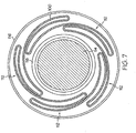
- FIG. 7 shows a section of heat shrink material 116 disposed about the folded balloon cylinder 100, which is disposed about catheter shaft(s) 118 that is disposed about mandrel 114.
- the section(s) of heat shrink material 116 is heated so that the heat shrink material 116 shrinks and provides a force against the weld region 120 that presses the folds 112 of the folded balloon cylinder 100 radially inward, which eliminates air pockets in the folds 112 of the balloon 100.
- the heat shrink material 116 has any length. In some embodiments, one section of heat shrink material 116 that has a length equal to the length of the balloon cylinder 100 is used. In other embodiments, two sections of heat shrink material 116 are used, with one section of heat shrink material 116 being placed over the proximal weld region 120 and the second section of heat shrink material 116 being disposed about the distal weld region 120. Any suitable heat shrink material 116 maybe used. Examples of suitable heat shrink material 116 which maybe used, include but are not limited to, polyethylene (e.g. polyolefin), RNF-100 which is a heat shrink tubing available from Raychem Corporation, KynarTM, nylon, polyvinalchloride, polytetrafluoroethylene and fluorinated ethylene polymer (FEP).
- polyethylene e.g. polyolefin
- RNF-100 which is a heat shrink tubing available from Raychem Corporation
- KynarTM nylon
- polyvinalchloride polytetrafluoroethylene and
- the folded balloon cylinder 100 is welded to the catheter shaft(s) 118 of a catheter to form a balloon catheter 122.
- there are two weld regions 120 a proximal weld region 120 at the proximal end region 106 of the balloon cylinder 100 and a distal weld region 120 at the distal end region 108 of the balloon cylinder 100.
- the folds 112 of the balloon cylinder 100 are welded directly to shaft(s) 118 of the balloon catheter 122 so that the balloon 100 does not have a waist.
- the balloon 100 has a low profile.
- Welds 120 are formed by any mechanism desired, for example, but not limited to, through transmission laser welding and direct or indirect application of heat to the weld site by any conventional method.
- welds are formed using a laser, e.g. a CO 2 laser or a diode laser. Examples of different weld 120 configurations and methods which may be used to weld the balloon wings 112 to the shaft(s) 118 are discussed in commonly assigned U.S. Application No. 11/526,322 entitled Designs for Balloon Welds.
- the heat from the laser further shrinks the heat shrink material 116, thereby squeezing the molten polymer layers together, as shown in FIG. 8 .
- the at least one section of heat shrink material 116 is removed from the balloon cylinder 100 after the balloon cylinder 100 has been welded to catheter shaft(s) 118.
- the weld 120 has even material thickness. In one embodiment, even material thickness of the weld 120 is obtained when the ends of the folds/pleats 112 do not overlap but have minimal separation, as shown for example, in FIG. 6 . As discussed in U.S. Application No. 11/526,322 , flexibility of the weld 120 can vary. In some embodiments, welding the balloon wings 100 to shaft(s) 118 increases the flexibility of the weld 120.
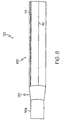
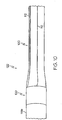
- FIGS. 9-11 are side views of the balloon catheter 122 with the balloon 100 in different states of expansion.
- the balloon 100 is in an unexpanded state in FIGS. 9 and 10 , and in an inflated or expanded state in FIG. 11 .
- FIG. 10 shows a balloon 100 that has been welded to an outer shaft 118a of the balloon catheter 122 that has a larger diameter than the inner shaft 118b of the balloon catheter 122 (note that the inner shaft 118b is not shown in FIG. 10 ).
- the balloon 100 has a smooth middle region 126 and pleated cone regions 124 when the balloon 100 is inflated, as shown in FIG. 11 .
- the folds 112 of the pleated cone regions 124 facilitate re-wrapping along the original folds 112.
- the balloon 100 can be "cone puffed." Cone puffing is the slight inflation of the balloon 100 after a stent has been crimped onto the balloon 100 while the stent is restrained to prevent expansion of the stent and is used to prevent slippage or movement of the stent.
- Polymeric materials that may be used for the shafts of balloon catheters include, but are not limited to, high density polyethylene (HDPE), polyamides, the polyetheramide copolymer family, HDPE with and without compatibilizers, low density polyethylene (LDPE), LDPE with and without compatibilizers, linear low density polyethylene (LLDPE), LLDPE with and without compatibilizers, polyethylene copolymers such as ethylene vinyl acetate copolymer (EVA) and other vinyl acetates, urethanes, polybutylene terephthalate (PBT), thermoplastic elastomers, isonomers, ethylene acrylic acid polymers, polyether block amide, and ethylene acrylic acid copolymer (EAA), polyurethane, polyesters such as polyethylene terephthalate (PET), polybutylene terephthalate (PBT), copolyesters such as Hytrel, other thermoplastic elastomers such as thermoplastic polyolefin (TPO), styrenic thermoplastic
- Polymer materials that can be used for balloons 10 include, but are not limited to, ethylene-vinyl acetate, polyvinyl chloride(PVC), olefin copolymers or homopolymers, polyethylenes, polyurethanes, crosslinked low density polyethylenes (PETs), highly irradiated linear low density polyethylene (LDPE), acrylonitrile polymers and copolymers, acrylonitrile blends and ionomer resins, polyethylene terephthalates, polyacrylenesulfide, and copolyesters, nylon, and polyamines.
- Other balloon materials may also be used.
- the balloon catheter may include one or more areas, bands, coatings, members, etc. that is (are) detectable by imaging modalities such as X-Ray, MRI, ultrasound, etc. In some embodiments at least a portion of the balloon catheter is at least partially radiopaque.
- any dependent claim which follows should be taken as alternatively written in a multiple dependent form from all prior claims which possess all antecedents referenced in such dependent claim if such multiple dependent format is an accepted format within the jurisdiction (e.g. each claim depending directly from claim 1 should be alternatively taken as depending from all previous claims).
- each claim depending directly from claim 1 should be alternatively taken as depending from all previous claims.
- the following dependent claims should each be also taken as alternatively written in each singly dependent claim format which creates a dependency from a prior antecedent-possessing claim other than the specific claim listed in such dependent claim below.
Landscapes
- Health & Medical Sciences (AREA)
- Life Sciences & Earth Sciences (AREA)
- Heart & Thoracic Surgery (AREA)
- Engineering & Computer Science (AREA)
- Biophysics (AREA)
- Pulmonology (AREA)
- Child & Adolescent Psychology (AREA)
- Anesthesiology (AREA)
- Biomedical Technology (AREA)
- Hematology (AREA)
- Animal Behavior & Ethology (AREA)
- General Health & Medical Sciences (AREA)
- Public Health (AREA)
- Veterinary Medicine (AREA)
- Media Introduction/Drainage Providing Device (AREA)
Description
- In some embodiments this invention relates to a balloon catheter with a balloon having folds or pleats that has been welded to at least one shaft, outer and/or inner, of the balloon catheter.
- Medical catheters having a balloon mounted thereon are useful in a variety of medical procedures. Balloon catheters may be used to widen a vessel into which the catheter is inserted by dilating the blocked vessel, such as in an angioplasty procedure. Balloon catheters may also be used to expand and/or seat a medical device such as a stent or graft at a desired position within a body lumen. In all of these applications, fluid under pressure may be supplied to the balloon through an inflation lumen in the catheter, thereby expanding the balloon.
- It is essential in the manufacture of balloon catheters to properly seal the balloon to the catheter, e.g. by welding. The seal must be able to withstand the high pressures to which it is subjected on inflation of the balloon. A poor seal may result in leakage of inflation fluid and inability to achieve the desired pressure or even rapid loss of pressure and deflation of the balloon. In addition, it is desirable to shape the outside surface of the weld region to provide a smooth transition from the outer shaft to the balloon.
-
FIG. 1 is an end view of a PRIORART balloon catheter 22. Knownballoon catheters 22, such as the example shown inFIG. 1 , have apreformed balloon 10 which has a center region 26, proximal anddistal cones 4, and proximal and distal waists. The waists of the balloon are welded 20 onto the shafts of thecatheter 22. Thecone 4 of theballoon 10 has a smooth surface and a large outer diameter at one end and a smaller outer diameter at the other end with increasing thickness as the outer diameter of thecone 4 is reduced. As shown inFIG. 1 , the center region of theballoon 10 is folded to a small outer diameter but the proximal anddistal cones 4 are not folded. This is due to the fact that theballoon 10 is folded after it has been welded onto theshafts 18 of theballoon catheter 22. Thus, there is a relatively bulky transition region between the center region 26 of theballoon 10 and thecone 4 that has an increased outer diameter. This relatively bulky transition region is caused by several factors which include bunching due to the fact that the folding does not end sharply and the increased thickness as the outer diameter of thecone 4 is reduced, as shown inFIG. 1 . -
US 4 941 877 A andUS 5 041 125 A disclose a balloon catheter having a balloon portion, transition zones at the respective end, in which the balloon tapers inwardly to the reduced diameters of proximal and distal portions. The transition zones comprise a plurality of flutes which are evenly distributed about the circumference of each transition zone. -
EP 0 730 879 A discloses a balloon catheter according to the preamble of claim 1 having a central section with on either side transition sections turning into end sections. During the manufacture of the balloon, ridges of material are formed in the transition sections. The ridges of material are thicker than the material in between. -
WO 2004/101059 A discloses a balloon catheter comprising folds. The folds are limited to the central portion of the balloon. - Without limiting the scope of the invention a brief summary of some of the claimed embodiments of the invention is set forth below. Additional details of the summarized embodiments of the invention and/or additional embodiments of the invention may be found in the Detailed Description of the Invention below.
- In at least one embodiment, the invention is directed to a balloon catheter where a balloon cylinder is folded to form pleats and then is welded directly to the catheter. The proximal portion of the balloon is welded to the outer shaft of the balloon catheter and the distal portion of the balloon is welded to the inner shaft of the balloon catheter.
- These and other embodiments which characterize the invention are pointed out with particularity in the claims annexed hereto and forming a part hereof. However, for further understanding of the invention, its advantages and objectives obtained by its use, reference can be made to the drawings which form a further part hereof and the accompanying descriptive matter, in which there is illustrated and described an embodiments of the invention.
- A detailed description of the invention is hereafter described with specific reference being made to the drawings.
-
FIG. 1 is an end view of a PRIOR ART balloon catheter. -
FIG. 2 is a side view of a balloon cylinder. -
FIG. 3 is the balloon cylinder ofFIG. 2 folded. -
FIG. 4 is a side view of the folded balloon cylinder ofFIG. 3 disposed about a catheter shaft which is disposed about a mandrel. -
FIG. 5 is a cross-sectional view ofFIG. 4 taken at line 5-5 showing a fold overlap embodiment. -
FIG. 6 is a cross-sectional view ofFIG. 4 taken at line 5-5 with another fold overlap embodiment. -
FIG. 7 is the cross-sectional view ofFIG. 5 with heatshrink surrounding the folded balloon at the weld region. -
FIG. 8 is the cross-sectional view ofFIG. 7 after the weld has been formed. -
FIG. 9 is a side view of the balloon catheter after the balloon has been welded to the catheter, with the balloon in a deflated state. -
FIG. 10 is a side view of the balloon catheter after the balloon has been welded to the catheter with a larger diameter proximal shaft, with the balloon in a deflated state. -
FIG. 11 is a side view of the balloon catheter inFIG. 9 with the balloon in an inflated state. - While this invention may be embodied in many different forms, there are described in detail herein specific embodiments of the invention. This description is an exemplification of the principles of the invention and is not intended to limit the invention to the particular embodiments illustrated.
- For the purposes of this disclosure, like reference numerals in the figures shall refer to like features unless otherwise indicated.
- The invention is directed to a
balloon catheter 122 with aballoon 100 that has folds orpleats 112 extending from a first end of theballoon 100 to a second end of the balloon, and that has been welded to at least oneshaft 118, outer and/or inner, of theballoon catheter 122. The disclosure is also directed to methods of making aballoon catheter 122 with aballoon 100 having folds orpleats 112 that has been welded to at least oneshaft 118, outer and/or inner, of theballoon catheter 122. As used in this application,shaft 118 includes both the outer shaft 118a and/or theinner shaft 118b of aballoon catheter 122. In at least one embodiment, theproximal end region 106 of aballoon 100 withpleats 112 is engaged to the outer shaft 118a of aballoon catheter 122 and thedistal end region 108 of theballoon 100 is engaged to theinner shaft 118b of theballoon catheter 122, where theinner shaft 118b extends distally from the distal end of the outer shaft 118a, as is known in the art. - The manufacture of the
inventive balloon catheter 122 begins with aballoon cylinder 100, as shown inFIG. 2 . Theballoon cylinder 100 has aproximal end region 106, amiddle region 126 and adistal end region 108. Theproximal end region 106 includes aweld region 120 and acone region 124, as shown inFIG. 11 . Similarly, thedistal end region 108 includes aweld region 120 and acone region 124. Each of the regions 106,124,108,120,126 has any longitudinal length. - The
balloon cylinder 100 is folded to form folds orpleats 112. In some embodiments, thefolds 112 extend along the entire longitudinal length of theballoon cylinder 100, i.e. from a first end of theballoon cylinder 100 to a second end of theballoon cylinder 100, as shown inFIG. 3 . In other embodiments, thefolds 112 are incorporated into the proximal and distal end regions 106,108 of theballoon cylinder 100 while themiddle region 126 of theballoon cylinder 100 has nofolds 112. In at least one embodiment, thefolds 112 are parallel to the longitudinal axis of theballoon cylinder 100. In other embodiments, thefolds 112 are at an oblique angle to the longitudinal axis of theballoon cylinder 100. An oblique angle, as used in this application, is an angle between 0 and 180 degrees and includes 90 degrees. - In some embodiments, the
balloon cylinder 100 is disposed about the catheter shaft(s) 118 of theballoon catheter 122, which is disposed about amandrel 114, then folds 112 are incorporated into theballoon cylinder 100 and then the foldedballoon cylinder 100 is welded to the catheter shaft(s) 118. In other embodiments, theballoon cylinder 100 is disposed about amandrel 114, folds 112 are incorporated into theballoon cylinder 100, themandrel 114 is removed and replaced with the catheter shaft(s) 118 of theballoon catheter 122 so that the foldedballoon cylinder 100 is disposed about the catheter shaft(s) 118 and then the foldedballoon cylinder 100 is welded to the catheter shaft(s) 118.FIG. 4 shows the foldedballoon cylinder 100 disposed about a catheter shaft(s) 118 which is disposed about amandrel 114. - Any method can be used to fold the
balloon cylinder 100, even methods used to fold theballoon 100 after it has been welded to the catheter shaft(s) 118 of theballoon catheter 122. As used in this application, the term "fold" includes pleats, wings, and any similar structure. Non-limiting examples of methods of balloon folding are discussed in commonly AssignedU.S. Patent Application Publication No. 2003/0163157 , entitled Balloon Folding Apparatus, Methods and Products and U.S. Patent Application Publication No.2005/0251194 , entitled Curved Wing Balloon and Manufacture thereof. -
FIGS. 5 and6 are cross-sectional views taken at line 5-5 ofFIG. 4 of theproximal end region 106 of theballoon cylinder 100 after it has been folded. Note that a cross-sectional view of thedistal end region 108 of theballoon cylinder 100 after it has been folded would have the same configuration. Theballoon cylinder 100 is disposed about the shaft(s) 118 of theballoon catheter 122 which is disposed aboutmandrel 114.FIGS. 5 and6 show two non-limiting examples of the placement of thefolds 112 formed in theballoon cylinder 100. In at least one embodiment, theends 113 of radiallyadjacent folds 112 are overlapping, as indicated by the box inFIG. 5 that surrounds one set of overlapping ends 113. It is within the scope of the invention for there to be any amount of overlap of the ends 113. In some embodiments, theends 113 overlap one another for the same distance. In other embodiments, theends 113 overlap one another for different distances. In at least one embodiment, theends 113 of radiallyadjacent folds 112 do not overlap, as shown by the box inFIG. 6 which is between the ends 113. It is within the scope of the invention for any distance to separate theends 113 of thefolds 112. In some embodiments, theends 113 are separated from one another by the same distance. In other embodiments, theends 113 are separated from one another by different distances. - In some embodiments, at least one section of
heat shrink material 116 is disposed about theballoon cylinder 100 after theballoon cylinder 100 is folded. In other embodiments, at least one section ofheat shrink material 116 is placed about theballoon cylinder 100 before theballoon cylinder 100 is folded.FIG. 7 shows a section ofheat shrink material 116 disposed about the foldedballoon cylinder 100, which is disposed about catheter shaft(s) 118 that is disposed aboutmandrel 114. In some embodiments, the section(s) ofheat shrink material 116 is heated so that theheat shrink material 116 shrinks and provides a force against theweld region 120 that presses thefolds 112 of the foldedballoon cylinder 100 radially inward, which eliminates air pockets in thefolds 112 of theballoon 100. - The
heat shrink material 116 has any length. In some embodiments, one section ofheat shrink material 116 that has a length equal to the length of theballoon cylinder 100 is used. In other embodiments, two sections ofheat shrink material 116 are used, with one section ofheat shrink material 116 being placed over theproximal weld region 120 and the second section ofheat shrink material 116 being disposed about thedistal weld region 120. Any suitableheat shrink material 116 maybe used. Examples of suitableheat shrink material 116 which maybe used, include but are not limited to, polyethylene (e.g. polyolefin), RNF-100 which is a heat shrink tubing available from Raychem Corporation, Kynar™, nylon, polyvinalchloride, polytetrafluoroethylene and fluorinated ethylene polymer (FEP). - The folded
balloon cylinder 100 is welded to the catheter shaft(s) 118 of a catheter to form aballoon catheter 122. Thus, in at least one embodiment, there are twoweld regions 120, aproximal weld region 120 at theproximal end region 106 of theballoon cylinder 100 and adistal weld region 120 at thedistal end region 108 of theballoon cylinder 100. In eachweld region 120, thefolds 112 of theballoon cylinder 100, are welded directly to shaft(s) 118 of theballoon catheter 122 so that theballoon 100 does not have a waist. In some embodiments, theballoon 100 has a low profile. -
Welds 120 are formed by any mechanism desired, for example, but not limited to, through transmission laser welding and direct or indirect application of heat to the weld site by any conventional method. In some embodiments, welds are formed using a laser, e.g. a CO2 laser or a diode laser. Examples ofdifferent weld 120 configurations and methods which may be used to weld theballoon wings 112 to the shaft(s) 118 are discussed in commonly assignedU.S. Application No. 11/526,322 entitled Designs for Balloon Welds. - If at least one section of
heat shrink material 116 has been disposed about theballoon cylinder 100, the heat from the laser further shrinks theheat shrink material 116, thereby squeezing the molten polymer layers together, as shown inFIG. 8 . In some embodiments, the at least one section ofheat shrink material 116 is removed from theballoon cylinder 100 after theballoon cylinder 100 has been welded to catheter shaft(s) 118. In at least one embodiment, theweld 120 has even material thickness. In one embodiment, even material thickness of theweld 120 is obtained when the ends of the folds/pleats 112 do not overlap but have minimal separation, as shown for example, inFIG. 6 . As discussed inU.S. Application No. 11/526,322 , flexibility of theweld 120 can vary. In some embodiments, welding theballoon wings 100 to shaft(s) 118 increases the flexibility of theweld 120. -
FIGS. 9-11 are side views of theballoon catheter 122 with theballoon 100 in different states of expansion. Theballoon 100 is in an unexpanded state inFIGS. 9 and10 , and in an inflated or expanded state inFIG. 11 .FIG. 10 shows aballoon 100 that has been welded to an outer shaft 118a of theballoon catheter 122 that has a larger diameter than theinner shaft 118b of the balloon catheter 122 (note that theinner shaft 118b is not shown inFIG. 10 ). The
balloon 100 has a smoothmiddle region 126 andpleated cone regions 124 when theballoon 100 is inflated, as shown inFIG. 11 . In some embodiments, thefolds 112 of thepleated cone regions 124 facilitate re-wrapping along the original folds 112. In at least one embodiment, theballoon 100 can be "cone puffed." Cone puffing is the slight inflation of theballoon 100 after a stent has been crimped onto theballoon 100 while the stent is restrained to prevent expansion of the stent and is used to prevent slippage or movement of the stent. - Polymeric materials that may be used for the shafts of balloon catheters include, but are not limited to, high density polyethylene (HDPE), polyamides, the polyetheramide copolymer family, HDPE with and without compatibilizers, low density polyethylene (LDPE), LDPE with and without compatibilizers, linear low density polyethylene (LLDPE), LLDPE with and without compatibilizers, polyethylene copolymers such as ethylene vinyl acetate copolymer (EVA) and other vinyl acetates, urethanes, polybutylene terephthalate (PBT), thermoplastic elastomers, isonomers, ethylene acrylic acid polymers, polyether block amide, and ethylene acrylic acid copolymer (EAA), polyurethane, polyesters such as polyethylene terephthalate (PET), polybutylene terephthalate (PBT), copolyesters such as Hytrel, other thermoplastic elastomers such as thermoplastic polyolefin (TPO), styrenic thermoplastic elastomers such as C-Flex, and ionomers such as Surlyn and any combination thereof.
- Polymer materials that can be used for
balloons 10 include, but are not limited to, ethylene-vinyl acetate, polyvinyl chloride(PVC), olefin copolymers or homopolymers, polyethylenes, polyurethanes, crosslinked low density polyethylenes (PETs), highly irradiated linear low density polyethylene (LDPE), acrylonitrile polymers and copolymers, acrylonitrile blends and ionomer resins, polyethylene terephthalates, polyacrylenesulfide, and copolyesters, nylon, and polyamines. Other balloon materials may also be used. - In some embodiments the balloon catheter may include one or more areas, bands, coatings, members, etc. that is (are) detectable by imaging modalities such as X-Ray, MRI, ultrasound, etc. In some embodiments at least a portion of the balloon catheter is at least partially radiopaque.
- The above disclosure is intended to be illustrative and not exhaustive. This description will suggest many variations and alternatives to one of ordinary skill in this art. The various elements shown in the individual figures and described above may be combined or modified for combination as desired. All these alternatives and variations are intended to be included within the scope of the claims where the term "comprising" means "including, but not limited to".
- Further, the particular features presented in the dependent claims can be combined with each other in other manners within the scope of the invention such that the invention should be recognized as also specifically directed to other embodiments having any other possible combination of the features of the dependent claims. For instance, for purposes of claim publication, any dependent claim which follows should be taken as alternatively written in a multiple dependent form from all prior claims which possess all antecedents referenced in such dependent claim if such multiple dependent format is an accepted format within the jurisdiction (e.g. each claim depending directly from claim 1 should be alternatively taken as depending from all previous claims). In jurisdictions where multiple dependent claim formats are restricted, the following dependent claims should each be also taken as alternatively written in each singly dependent claim format which creates a dependency from a prior antecedent-possessing claim other than the specific claim listed in such dependent claim below.
- This completes the description of the invention. Those skilled in the art may recognize other equivalents to the specific embodiment described herein which equivalents are intended to be encompassed by the claims attached hereto.
Claims (4)
- A balloon catheter, the balloon catheter comprising:at least one shaft (118); anda balloon (100), the balloon (100) comprising a first weld region (120), a first cone region (124), a middle region (126), a second cone region (124) and a second weld region (120), the first weld region (120) engaging the balloon (100) to the at least one shaft (118), the first cone region (124) adjacent to the first weld region (120), the middle region (126) between the first cone region (124) and the second cone region (124), the second cone region (124) adjacent to the second weld region (120), the second weld region (120) engaging the balloon (100) to the at least one shaft (118), the balloon (100) having an uninflated state and an inflated state, characterized in that the balloon (100) has at least one fold (112) extending from the first weld region (120) to the second weld region (120) in the uninflated state and the first and second cone regions (124) of the balloon (100) have at least one fold (112) and are pleated in the inflated state, wherein the middle region (126) is smooth when the balloon (100) is inflated.
- The balloon catheter of claim 1, the at least one shaft (118) comprising an outer shaft (118a) and an inner shaft (118b), the first weld region (120) engaging the balloon (100) to a portion of the outer shaft (118a) and the second weld region (120) engaging the balloon to a portion of the inner shaft (118b).
- The balloon catheter of claim 1, the at least one fold (112) being a plurality of folds, each of the plurality of folds (112) having a first end and a second end, radially adjacent ends being overlapping.
- The balloon catheter of claim 1, the at least one fold (112) being a plurality of folds, the plurality of folds (112) having even material thickness.
Applications Claiming Priority (2)
| Application Number | Priority Date | Filing Date | Title |
|---|---|---|---|
| US12/129,380 US7828767B2 (en) | 2008-05-29 | 2008-05-29 | Balloon design and weld design to increase ease of re-wrapping and decrease withdrawal force |
| PCT/US2009/044692 WO2009146285A1 (en) | 2008-05-29 | 2009-05-20 | Balloon design and weld design to increase ease of re-wrapping and decrease withdrawal force |
Publications (3)
| Publication Number | Publication Date |
|---|---|
| EP2320983A1 EP2320983A1 (en) | 2011-05-18 |
| EP2320983B1 EP2320983B1 (en) | 2015-11-04 |
| EP2320983B2 true EP2320983B2 (en) | 2019-11-27 |
Family
ID=41009880
Family Applications (1)
| Application Number | Title | Priority Date | Filing Date |
|---|---|---|---|
| EP09755647.6A Active EP2320983B2 (en) | 2008-05-29 | 2009-05-20 | Balloon design and weld design to increase ease of re-wrapping and decrease withdrawal force |
Country Status (3)
| Country | Link |
|---|---|
| US (1) | US7828767B2 (en) |
| EP (1) | EP2320983B2 (en) |
| WO (1) | WO2009146285A1 (en) |
Families Citing this family (7)
| Publication number | Priority date | Publication date | Assignee | Title |
|---|---|---|---|---|
| US8337480B2 (en) * | 2005-08-19 | 2012-12-25 | Abbott Laboratories Vascular Enterprises Limited | Method of producing a balloon of a balloon catheter |
| JP2014147585A (en) * | 2013-02-01 | 2014-08-21 | Asahi Intecc Co Ltd | Balloon catheter |
| JP6632548B2 (en) * | 2014-06-17 | 2020-01-22 | コヴィディエン リミテッド パートナーシップ | Medical balloon with groove |
| JP2016013215A (en) * | 2014-07-01 | 2016-01-28 | 朝日インテック株式会社 | Balloon catheter |
| CN107715282A (en) * | 2017-11-08 | 2018-02-23 | 柏文有限责任公司 | A kind of medical dilating sacculus |
| WO2020196231A1 (en) * | 2019-03-22 | 2020-10-01 | テルモ株式会社 | Balloon catheter and balloon arrangement method |
| CN110420375B (en) * | 2019-06-27 | 2022-09-02 | 先健科技(深圳)有限公司 | Balloon catheter and manufacturing method thereof |
Citations (19)
| Publication number | Priority date | Publication date | Assignee | Title |
|---|---|---|---|---|
| US5053007A (en) † | 1989-12-14 | 1991-10-01 | Scimed Life Systems, Inc. | Compression balloon protector for a balloon dilatation catheter and method of use thereof |
| US5304197A (en) † | 1988-10-04 | 1994-04-19 | Cordis Corporation | Balloons for medical devices and fabrication thereof |
| WO1997025093A1 (en) † | 1996-01-04 | 1997-07-17 | Leocor, Inc. | Fluted balloon catheter |
| WO1997026040A1 (en) † | 1996-01-19 | 1997-07-24 | Mario Immacolato Paternuosto | An isolated operating-room providing probe for the distal end of the oesophagus |
| US5853389A (en) † | 1996-03-07 | 1998-12-29 | Cordis Corporation | Balloon catheter and method for manufacturing |
| US6013055A (en) † | 1997-11-13 | 2000-01-11 | Boston Scientific Corporation | Catheter balloon having selected folding characteristics |
| US20010047149A1 (en) † | 1998-03-04 | 2001-11-29 | Scimed Life Systems, Inc. | Balloon wrap device and method |
| US20030163157A1 (en) † | 2002-02-28 | 2003-08-28 | Scimed Life Systems, Inc. | Balloon folding apparatus, methods and products |
| WO2005032641A1 (en) † | 2003-09-17 | 2005-04-14 | Boston Scientific Limited | Balloon assembly with a torque |
| WO2005076833A2 (en) † | 2004-02-10 | 2005-08-25 | Angioscore, Inc. | Balloon catheter with spiral folds |
| US20050251194A1 (en) † | 2002-03-27 | 2005-11-10 | Boston Scientific Scimed, Inc. | Curved wing balloon and manufacture thereof |
| WO2005113058A1 (en) † | 2004-05-21 | 2005-12-01 | Medtronic Vascular Inc. | Folded balloon for catheter |
| EP1611917A1 (en) † | 1995-10-11 | 2006-01-04 | Terumo Kabushiki Kaisha | Catheter balloon and balloon catheter |
| US20060004399A1 (en) † | 2004-06-30 | 2006-01-05 | Van Ockenburg Ben | Methods of making balloon catheter tip |
| US20060112536A1 (en) † | 2003-09-15 | 2006-06-01 | Atrium Medical Corporation | Method of coating a folded medical device |
| WO2007020087A1 (en) † | 2005-08-19 | 2007-02-22 | Abbott Laboratories Vascular Enterprises Limited | Method of producing a balloon of a balloon catheter |
| WO2007040659A1 (en) † | 2005-09-23 | 2007-04-12 | Boston Scientific Limited, Inc. | A secured stent delivery system |
| EP1867358A1 (en) † | 2006-06-13 | 2007-12-19 | DSMIP Assets B.V. | Instrument for expanding a stent |
| EP1897584A1 (en) † | 2006-09-07 | 2008-03-12 | Manuel Parente | Angioplasty catheter |
Family Cites Families (8)
| Publication number | Priority date | Publication date | Assignee | Title |
|---|---|---|---|---|
| US5041125A (en) * | 1989-01-26 | 1991-08-20 | Cordis Corporation | Balloon catheter |
| US4941877A (en) * | 1989-01-26 | 1990-07-17 | Cordis Corporation | Balloon catheter |
| NL9500468A (en) | 1995-03-08 | 1996-10-01 | Cordis Europ | Balloon catheter and method of making it. |
| US6071285A (en) * | 1996-03-25 | 2000-06-06 | Lashinski; Robert D. | Rapid exchange folded balloon catheter and stent delivery system |
| US6740191B2 (en) * | 2001-02-22 | 2004-05-25 | Medtronic Ave, Inc. | Through-transmission welding of catheter components |
| US20040236366A1 (en) | 2002-05-16 | 2004-11-25 | Kennedy Kenneth C. | Non-buckling balloon catheter |
| US7419563B2 (en) * | 2005-06-23 | 2008-09-02 | Boston Scientific Scimed, Inc. | Methods of making medical devices |
| JP2009519770A (en) * | 2005-12-16 | 2009-05-21 | インターフェイス・アソシエイツ・インコーポレーテッド | Medical multilayer balloon and method for producing the same |
-
2008
- 2008-05-29 US US12/129,380 patent/US7828767B2/en active Active
-
2009
- 2009-05-20 WO PCT/US2009/044692 patent/WO2009146285A1/en active Application Filing
- 2009-05-20 EP EP09755647.6A patent/EP2320983B2/en active Active
Patent Citations (19)
| Publication number | Priority date | Publication date | Assignee | Title |
|---|---|---|---|---|
| US5304197A (en) † | 1988-10-04 | 1994-04-19 | Cordis Corporation | Balloons for medical devices and fabrication thereof |
| US5053007A (en) † | 1989-12-14 | 1991-10-01 | Scimed Life Systems, Inc. | Compression balloon protector for a balloon dilatation catheter and method of use thereof |
| EP1611917A1 (en) † | 1995-10-11 | 2006-01-04 | Terumo Kabushiki Kaisha | Catheter balloon and balloon catheter |
| WO1997025093A1 (en) † | 1996-01-04 | 1997-07-17 | Leocor, Inc. | Fluted balloon catheter |
| WO1997026040A1 (en) † | 1996-01-19 | 1997-07-24 | Mario Immacolato Paternuosto | An isolated operating-room providing probe for the distal end of the oesophagus |
| US5853389A (en) † | 1996-03-07 | 1998-12-29 | Cordis Corporation | Balloon catheter and method for manufacturing |
| US6013055A (en) † | 1997-11-13 | 2000-01-11 | Boston Scientific Corporation | Catheter balloon having selected folding characteristics |
| US20010047149A1 (en) † | 1998-03-04 | 2001-11-29 | Scimed Life Systems, Inc. | Balloon wrap device and method |
| US20030163157A1 (en) † | 2002-02-28 | 2003-08-28 | Scimed Life Systems, Inc. | Balloon folding apparatus, methods and products |
| US20050251194A1 (en) † | 2002-03-27 | 2005-11-10 | Boston Scientific Scimed, Inc. | Curved wing balloon and manufacture thereof |
| US20060112536A1 (en) † | 2003-09-15 | 2006-06-01 | Atrium Medical Corporation | Method of coating a folded medical device |
| WO2005032641A1 (en) † | 2003-09-17 | 2005-04-14 | Boston Scientific Limited | Balloon assembly with a torque |
| WO2005076833A2 (en) † | 2004-02-10 | 2005-08-25 | Angioscore, Inc. | Balloon catheter with spiral folds |
| WO2005113058A1 (en) † | 2004-05-21 | 2005-12-01 | Medtronic Vascular Inc. | Folded balloon for catheter |
| US20060004399A1 (en) † | 2004-06-30 | 2006-01-05 | Van Ockenburg Ben | Methods of making balloon catheter tip |
| WO2007020087A1 (en) † | 2005-08-19 | 2007-02-22 | Abbott Laboratories Vascular Enterprises Limited | Method of producing a balloon of a balloon catheter |
| WO2007040659A1 (en) † | 2005-09-23 | 2007-04-12 | Boston Scientific Limited, Inc. | A secured stent delivery system |
| EP1867358A1 (en) † | 2006-06-13 | 2007-12-19 | DSMIP Assets B.V. | Instrument for expanding a stent |
| EP1897584A1 (en) † | 2006-09-07 | 2008-03-12 | Manuel Parente | Angioplasty catheter |
Also Published As
| Publication number | Publication date |
|---|---|
| US7828767B2 (en) | 2010-11-09 |
| EP2320983A1 (en) | 2011-05-18 |
| WO2009146285A1 (en) | 2009-12-03 |
| US20090299283A1 (en) | 2009-12-03 |
| EP2320983B1 (en) | 2015-11-04 |
| WO2009146285A9 (en) | 2010-03-04 |
Similar Documents
| Publication | Publication Date | Title |
|---|---|---|
| EP2320983B2 (en) | Balloon design and weld design to increase ease of re-wrapping and decrease withdrawal force | |
| JP3968444B2 (en) | Stent delivery mechanism with stent fixation device | |
| US6607552B1 (en) | Rolling socks | |
| EP1480709B1 (en) | Balloon catheter for creating a longitudinal channel in a lesion and method | |
| US6432129B2 (en) | Stent delivery system | |
| EP2714180B1 (en) | Catheter with stepped skived hypotube | |
| EP1962939B1 (en) | Non-compliant multilayered balloon for a catheter | |
| EP2254645B1 (en) | Method of forming a cutting balloon with connector and dilation element | |
| US6159227A (en) | Balloon catheter with stent securement means | |
| US8021330B2 (en) | Balloon catheter for crossing a chronic total occlusion | |
| CA2191452C (en) | Catheter with balloon folding into predetermined configurations and method of manufacture | |
| CN118217058A (en) | Expandable sheath | |
| US20070138694A1 (en) | Catheter balloon | |
| CN105582611B (en) | Balloon catheter | |
| US9381327B2 (en) | Balloon catheter | |
| CN105536121B (en) | Balloon catheter | |
| US20160022969A1 (en) | Balloon catheter and manufacturing method of balloon catheter | |
| CN116157173A (en) | Expandable introducer for expanding distal tip of introducer sheath | |
| EP0737084B1 (en) | Slip-layered catheter balloon | |
| US11992635B2 (en) | Medical balloon assembly | |
| US20240226512A1 (en) | Tapered balloon | |
| CA2179636C (en) | Slip-layered catheter balloon | |
| AU766834B2 (en) | Stent delivery system having stent securement apparatus |
Legal Events
| Date | Code | Title | Description |
|---|---|---|---|
| PUAI | Public reference made under article 153(3) epc to a published international application that has entered the european phase |
Free format text: ORIGINAL CODE: 0009012 |
|
| 17P | Request for examination filed |
Effective date: 20101218 |
|
| AK | Designated contracting states |
Kind code of ref document: A1 Designated state(s): AT BE BG CH CY CZ DE DK EE ES FI FR GB GR HR HU IE IS IT LI LT LU LV MC MK MT NL NO PL PT RO SE SI SK TR |
|
| AX | Request for extension of the european patent |
Extension state: AL BA RS |
|
| DAX | Request for extension of the european patent (deleted) | ||
| 17Q | First examination report despatched |
Effective date: 20130412 |
|
| GRAP | Despatch of communication of intention to grant a patent |
Free format text: ORIGINAL CODE: EPIDOSNIGR1 |
|
| INTG | Intention to grant announced |
Effective date: 20150512 |
|
| GRAS | Grant fee paid |
Free format text: ORIGINAL CODE: EPIDOSNIGR3 |
|
| GRAA | (expected) grant |
Free format text: ORIGINAL CODE: 0009210 |
|
| AK | Designated contracting states |
Kind code of ref document: B1 Designated state(s): AT BE BG CH CY CZ DE DK EE ES FI FR GB GR HR HU IE IS IT LI LT LU LV MC MK MT NL NO PL PT RO SE SI SK TR |
|
| REG | Reference to a national code |
Ref country code: GB Ref legal event code: FG4D |
|
| REG | Reference to a national code |
Ref country code: CH Ref legal event code: EP |
|
| REG | Reference to a national code |
Ref country code: AT Ref legal event code: REF Ref document number: 758762 Country of ref document: AT Kind code of ref document: T Effective date: 20151115 |
|
| REG | Reference to a national code |
Ref country code: IE Ref legal event code: FG4D |
|
| REG | Reference to a national code |
Ref country code: DE Ref legal event code: R096 Ref document number: 602009034638 Country of ref document: DE |
|
| REG | Reference to a national code |
Ref country code: NL Ref legal event code: MP Effective date: 20151104 |
|
| REG | Reference to a national code |
Ref country code: LT Ref legal event code: MG4D |
|
| REG | Reference to a national code |
Ref country code: AT Ref legal event code: MK05 Ref document number: 758762 Country of ref document: AT Kind code of ref document: T Effective date: 20151104 |
|
| PG25 | Lapsed in a contracting state [announced via postgrant information from national office to epo] |
Ref country code: NL Free format text: LAPSE BECAUSE OF FAILURE TO SUBMIT A TRANSLATION OF THE DESCRIPTION OR TO PAY THE FEE WITHIN THE PRESCRIBED TIME-LIMIT Effective date: 20151104 Ref country code: ES Free format text: LAPSE BECAUSE OF FAILURE TO SUBMIT A TRANSLATION OF THE DESCRIPTION OR TO PAY THE FEE WITHIN THE PRESCRIBED TIME-LIMIT Effective date: 20151104 Ref country code: HR Free format text: LAPSE BECAUSE OF FAILURE TO SUBMIT A TRANSLATION OF THE DESCRIPTION OR TO PAY THE FEE WITHIN THE PRESCRIBED TIME-LIMIT Effective date: 20151104 Ref country code: IS Free format text: LAPSE BECAUSE OF FAILURE TO SUBMIT A TRANSLATION OF THE DESCRIPTION OR TO PAY THE FEE WITHIN THE PRESCRIBED TIME-LIMIT Effective date: 20160304 Ref country code: LT Free format text: LAPSE BECAUSE OF FAILURE TO SUBMIT A TRANSLATION OF THE DESCRIPTION OR TO PAY THE FEE WITHIN THE PRESCRIBED TIME-LIMIT Effective date: 20151104 Ref country code: NO Free format text: LAPSE BECAUSE OF FAILURE TO SUBMIT A TRANSLATION OF THE DESCRIPTION OR TO PAY THE FEE WITHIN THE PRESCRIBED TIME-LIMIT Effective date: 20160204 Ref country code: IT Free format text: LAPSE BECAUSE OF FAILURE TO SUBMIT A TRANSLATION OF THE DESCRIPTION OR TO PAY THE FEE WITHIN THE PRESCRIBED TIME-LIMIT Effective date: 20151104 |
|
| PG25 | Lapsed in a contracting state [announced via postgrant information from national office to epo] |
Ref country code: PT Free format text: LAPSE BECAUSE OF FAILURE TO SUBMIT A TRANSLATION OF THE DESCRIPTION OR TO PAY THE FEE WITHIN THE PRESCRIBED TIME-LIMIT Effective date: 20160304 Ref country code: GR Free format text: LAPSE BECAUSE OF FAILURE TO SUBMIT A TRANSLATION OF THE DESCRIPTION OR TO PAY THE FEE WITHIN THE PRESCRIBED TIME-LIMIT Effective date: 20160205 Ref country code: AT Free format text: LAPSE BECAUSE OF FAILURE TO SUBMIT A TRANSLATION OF THE DESCRIPTION OR TO PAY THE FEE WITHIN THE PRESCRIBED TIME-LIMIT Effective date: 20151104 Ref country code: PL Free format text: LAPSE BECAUSE OF FAILURE TO SUBMIT A TRANSLATION OF THE DESCRIPTION OR TO PAY THE FEE WITHIN THE PRESCRIBED TIME-LIMIT Effective date: 20151104 Ref country code: SE Free format text: LAPSE BECAUSE OF FAILURE TO SUBMIT A TRANSLATION OF THE DESCRIPTION OR TO PAY THE FEE WITHIN THE PRESCRIBED TIME-LIMIT Effective date: 20151104 Ref country code: LV Free format text: LAPSE BECAUSE OF FAILURE TO SUBMIT A TRANSLATION OF THE DESCRIPTION OR TO PAY THE FEE WITHIN THE PRESCRIBED TIME-LIMIT Effective date: 20151104 Ref country code: FI Free format text: LAPSE BECAUSE OF FAILURE TO SUBMIT A TRANSLATION OF THE DESCRIPTION OR TO PAY THE FEE WITHIN THE PRESCRIBED TIME-LIMIT Effective date: 20151104 |
|
| PG25 | Lapsed in a contracting state [announced via postgrant information from national office to epo] |
Ref country code: CZ Free format text: LAPSE BECAUSE OF FAILURE TO SUBMIT A TRANSLATION OF THE DESCRIPTION OR TO PAY THE FEE WITHIN THE PRESCRIBED TIME-LIMIT Effective date: 20151104 |
|
| REG | Reference to a national code |
Ref country code: DE Ref legal event code: R026 Ref document number: 602009034638 Country of ref document: DE |
|
| PLBI | Opposition filed |
Free format text: ORIGINAL CODE: 0009260 |
|
| PG25 | Lapsed in a contracting state [announced via postgrant information from national office to epo] |
Ref country code: SK Free format text: LAPSE BECAUSE OF FAILURE TO SUBMIT A TRANSLATION OF THE DESCRIPTION OR TO PAY THE FEE WITHIN THE PRESCRIBED TIME-LIMIT Effective date: 20151104 Ref country code: DK Free format text: LAPSE BECAUSE OF FAILURE TO SUBMIT A TRANSLATION OF THE DESCRIPTION OR TO PAY THE FEE WITHIN THE PRESCRIBED TIME-LIMIT Effective date: 20151104 Ref country code: RO Free format text: LAPSE BECAUSE OF FAILURE TO SUBMIT A TRANSLATION OF THE DESCRIPTION OR TO PAY THE FEE WITHIN THE PRESCRIBED TIME-LIMIT Effective date: 20151104 Ref country code: EE Free format text: LAPSE BECAUSE OF FAILURE TO SUBMIT A TRANSLATION OF THE DESCRIPTION OR TO PAY THE FEE WITHIN THE PRESCRIBED TIME-LIMIT Effective date: 20151104 Ref country code: BE Free format text: LAPSE BECAUSE OF NON-PAYMENT OF DUE FEES Effective date: 20160531 |
|
| 26 | Opposition filed |
Opponent name: EDWARDS LIFESCIENCES CORPORATION Effective date: 20160803 |
|
| PLAX | Notice of opposition and request to file observation + time limit sent |
Free format text: ORIGINAL CODE: EPIDOSNOBS2 |
|
| PG25 | Lapsed in a contracting state [announced via postgrant information from national office to epo] |
Ref country code: SI Free format text: LAPSE BECAUSE OF FAILURE TO SUBMIT A TRANSLATION OF THE DESCRIPTION OR TO PAY THE FEE WITHIN THE PRESCRIBED TIME-LIMIT Effective date: 20151104 |
|
| PG25 | Lapsed in a contracting state [announced via postgrant information from national office to epo] |
Ref country code: LU Free format text: LAPSE BECAUSE OF FAILURE TO SUBMIT A TRANSLATION OF THE DESCRIPTION OR TO PAY THE FEE WITHIN THE PRESCRIBED TIME-LIMIT Effective date: 20160520 Ref country code: BE Free format text: LAPSE BECAUSE OF FAILURE TO SUBMIT A TRANSLATION OF THE DESCRIPTION OR TO PAY THE FEE WITHIN THE PRESCRIBED TIME-LIMIT Effective date: 20151104 |
|
| REG | Reference to a national code |
Ref country code: CH Ref legal event code: PL |
|
| PLBB | Reply of patent proprietor to notice(s) of opposition received |
Free format text: ORIGINAL CODE: EPIDOSNOBS3 |
|
| GBPC | Gb: european patent ceased through non-payment of renewal fee |
Effective date: 20160520 |
|
| PG25 | Lapsed in a contracting state [announced via postgrant information from national office to epo] |
Ref country code: LI Free format text: LAPSE BECAUSE OF NON-PAYMENT OF DUE FEES Effective date: 20160531 Ref country code: CH Free format text: LAPSE BECAUSE OF NON-PAYMENT OF DUE FEES Effective date: 20160531 |
|
| REG | Reference to a national code |
Ref country code: FR Ref legal event code: ST Effective date: 20170131 |
|
| PG25 | Lapsed in a contracting state [announced via postgrant information from national office to epo] |
Ref country code: FR Free format text: LAPSE BECAUSE OF NON-PAYMENT OF DUE FEES Effective date: 20160531 |
|
| PG25 | Lapsed in a contracting state [announced via postgrant information from national office to epo] |
Ref country code: GB Free format text: LAPSE BECAUSE OF NON-PAYMENT OF DUE FEES Effective date: 20160520 |
|
| APBM | Appeal reference recorded |
Free format text: ORIGINAL CODE: EPIDOSNREFNO |
|
| APBP | Date of receipt of notice of appeal recorded |
Free format text: ORIGINAL CODE: EPIDOSNNOA2O |
|
| APAH | Appeal reference modified |
Free format text: ORIGINAL CODE: EPIDOSCREFNO |
|
| PG25 | Lapsed in a contracting state [announced via postgrant information from national office to epo] |
Ref country code: CY Free format text: LAPSE BECAUSE OF FAILURE TO SUBMIT A TRANSLATION OF THE DESCRIPTION OR TO PAY THE FEE WITHIN THE PRESCRIBED TIME-LIMIT Effective date: 20151104 Ref country code: HU Free format text: LAPSE BECAUSE OF FAILURE TO SUBMIT A TRANSLATION OF THE DESCRIPTION OR TO PAY THE FEE WITHIN THE PRESCRIBED TIME-LIMIT; INVALID AB INITIO Effective date: 20090520 |
|
| PG25 | Lapsed in a contracting state [announced via postgrant information from national office to epo] |
Ref country code: MT Free format text: LAPSE BECAUSE OF NON-PAYMENT OF DUE FEES Effective date: 20160531 Ref country code: MK Free format text: LAPSE BECAUSE OF FAILURE TO SUBMIT A TRANSLATION OF THE DESCRIPTION OR TO PAY THE FEE WITHIN THE PRESCRIBED TIME-LIMIT Effective date: 20151104 Ref country code: TR Free format text: LAPSE BECAUSE OF FAILURE TO SUBMIT A TRANSLATION OF THE DESCRIPTION OR TO PAY THE FEE WITHIN THE PRESCRIBED TIME-LIMIT Effective date: 20151104 Ref country code: MC Free format text: LAPSE BECAUSE OF FAILURE TO SUBMIT A TRANSLATION OF THE DESCRIPTION OR TO PAY THE FEE WITHIN THE PRESCRIBED TIME-LIMIT Effective date: 20151104 |
|
| PG25 | Lapsed in a contracting state [announced via postgrant information from national office to epo] |
Ref country code: BG Free format text: LAPSE BECAUSE OF FAILURE TO SUBMIT A TRANSLATION OF THE DESCRIPTION OR TO PAY THE FEE WITHIN THE PRESCRIBED TIME-LIMIT Effective date: 20151104 |
|
| APBQ | Date of receipt of statement of grounds of appeal recorded |
Free format text: ORIGINAL CODE: EPIDOSNNOA3O |
|
| PLBP | Opposition withdrawn |
Free format text: ORIGINAL CODE: 0009264 |
|
| APBU | Appeal procedure closed |
Free format text: ORIGINAL CODE: EPIDOSNNOA9O |
|
| PUAH | Patent maintained in amended form |
Free format text: ORIGINAL CODE: 0009272 |
|
| STAA | Information on the status of an ep patent application or granted ep patent |
Free format text: STATUS: PATENT MAINTAINED AS AMENDED |
|
| 27A | Patent maintained in amended form |
Effective date: 20191127 |
|
| AK | Designated contracting states |
Kind code of ref document: B2 Designated state(s): AT BE BG CH CY CZ DE DK EE ES FI FR GB GR HR HU IE IS IT LI LT LU LV MC MK MT NL NO PL PT RO SE SI SK TR |
|
| REG | Reference to a national code |
Ref country code: DE Ref legal event code: R102 Ref document number: 602009034638 Country of ref document: DE |
|
| P01 | Opt-out of the competence of the unified patent court (upc) registered |
Effective date: 20230523 |
|
| PGFP | Annual fee paid to national office [announced via postgrant information from national office to epo] |
Ref country code: IE Payment date: 20240419 Year of fee payment: 16 |
|
| PGFP | Annual fee paid to national office [announced via postgrant information from national office to epo] |
Ref country code: DE Payment date: 20240418 Year of fee payment: 16 |