EP2320256A1 - Optical fiber manufacturing method - Google Patents
Optical fiber manufacturing method Download PDFInfo
- Publication number
- EP2320256A1 EP2320256A1 EP10251745A EP10251745A EP2320256A1 EP 2320256 A1 EP2320256 A1 EP 2320256A1 EP 10251745 A EP10251745 A EP 10251745A EP 10251745 A EP10251745 A EP 10251745A EP 2320256 A1 EP2320256 A1 EP 2320256A1
- Authority
- EP
- European Patent Office
- Prior art keywords
- optical fiber
- base materials
- bundle
- core
- elongating
- Prior art date
- Legal status (The legal status is an assumption and is not a legal conclusion. Google has not performed a legal analysis and makes no representation as to the accuracy of the status listed.)
- Withdrawn
Links
- 239000013307 optical fiber Substances 0.000 title claims abstract description 95
- 238000004519 manufacturing process Methods 0.000 title claims abstract description 39
- 239000000463 material Substances 0.000 claims abstract description 142
- 238000005253 cladding Methods 0.000 claims abstract description 47
- 239000011162 core material Substances 0.000 description 166
- 238000000034 method Methods 0.000 description 75
- 239000011521 glass Substances 0.000 description 14
- 230000005540 biological transmission Effects 0.000 description 11
- 239000007787 solid Substances 0.000 description 8
- 238000010586 diagram Methods 0.000 description 7
- 230000003287 optical effect Effects 0.000 description 7
- 239000000835 fiber Substances 0.000 description 5
- 230000001902 propagating effect Effects 0.000 description 5
- VYPSYNLAJGMNEJ-UHFFFAOYSA-N Silicium dioxide Chemical compound O=[Si]=O VYPSYNLAJGMNEJ-UHFFFAOYSA-N 0.000 description 4
- 230000003247 decreasing effect Effects 0.000 description 4
- 238000005553 drilling Methods 0.000 description 4
- 238000007796 conventional method Methods 0.000 description 3
- KRHYYFGTRYWZRS-UHFFFAOYSA-N Fluorane Chemical compound F KRHYYFGTRYWZRS-UHFFFAOYSA-N 0.000 description 2
- 230000008901 benefit Effects 0.000 description 2
- 238000005530 etching Methods 0.000 description 2
- 238000003780 insertion Methods 0.000 description 2
- 230000037431 insertion Effects 0.000 description 2
- 235000012239 silicon dioxide Nutrition 0.000 description 2
- KRHYYFGTRYWZRS-UHFFFAOYSA-M Fluoride anion Chemical compound [F-] KRHYYFGTRYWZRS-UHFFFAOYSA-M 0.000 description 1
- 230000002159 abnormal effect Effects 0.000 description 1
- 238000005229 chemical vapour deposition Methods 0.000 description 1
- 239000000470 constituent Substances 0.000 description 1
- 238000010276 construction Methods 0.000 description 1
- 238000000151 deposition Methods 0.000 description 1
- 230000008021 deposition Effects 0.000 description 1
- 239000006185 dispersion Substances 0.000 description 1
- 239000002019 doping agent Substances 0.000 description 1
- 238000005516 engineering process Methods 0.000 description 1
- 229910052732 germanium Inorganic materials 0.000 description 1
- GNPVGFCGXDBREM-UHFFFAOYSA-N germanium atom Chemical compound [Ge] GNPVGFCGXDBREM-UHFFFAOYSA-N 0.000 description 1
- 238000010438 heat treatment Methods 0.000 description 1
- 239000007788 liquid Substances 0.000 description 1
- 238000012986 modification Methods 0.000 description 1
- 230000004048 modification Effects 0.000 description 1
- 238000005498 polishing Methods 0.000 description 1
- 238000003980 solgel method Methods 0.000 description 1
- 239000012808 vapor phase Substances 0.000 description 1
Images


Classifications
-
- G—PHYSICS
- G02—OPTICS
- G02B—OPTICAL ELEMENTS, SYSTEMS OR APPARATUS
- G02B6/00—Light guides; Structural details of arrangements comprising light guides and other optical elements, e.g. couplings
- G02B6/02—Optical fibres with cladding with or without a coating
- G02B6/02042—Multicore optical fibres
-
- C—CHEMISTRY; METALLURGY
- C03—GLASS; MINERAL OR SLAG WOOL
- C03B—MANUFACTURE, SHAPING, OR SUPPLEMENTARY PROCESSES
- C03B37/00—Manufacture or treatment of flakes, fibres, or filaments from softened glass, minerals, or slags
- C03B37/01—Manufacture of glass fibres or filaments
- C03B37/012—Manufacture of preforms for drawing fibres or filaments
- C03B37/01205—Manufacture of preforms for drawing fibres or filaments starting from tubes, rods, fibres or filaments
- C03B37/01211—Manufacture of preforms for drawing fibres or filaments starting from tubes, rods, fibres or filaments by inserting one or more rods or tubes into a tube
- C03B37/01214—Manufacture of preforms for drawing fibres or filaments starting from tubes, rods, fibres or filaments by inserting one or more rods or tubes into a tube for making preforms of multifibres, fibre bundles other than multiple core preforms
-
- C—CHEMISTRY; METALLURGY
- C03—GLASS; MINERAL OR SLAG WOOL
- C03B—MANUFACTURE, SHAPING, OR SUPPLEMENTARY PROCESSES
- C03B37/00—Manufacture or treatment of flakes, fibres, or filaments from softened glass, minerals, or slags
- C03B37/01—Manufacture of glass fibres or filaments
- C03B37/012—Manufacture of preforms for drawing fibres or filaments
- C03B37/01205—Manufacture of preforms for drawing fibres or filaments starting from tubes, rods, fibres or filaments
- C03B37/01211—Manufacture of preforms for drawing fibres or filaments starting from tubes, rods, fibres or filaments by inserting one or more rods or tubes into a tube
- C03B37/0122—Manufacture of preforms for drawing fibres or filaments starting from tubes, rods, fibres or filaments by inserting one or more rods or tubes into a tube for making preforms of photonic crystal, microstructured or holey optical fibres
-
- C—CHEMISTRY; METALLURGY
- C03—GLASS; MINERAL OR SLAG WOOL
- C03B—MANUFACTURE, SHAPING, OR SUPPLEMENTARY PROCESSES
- C03B2203/00—Fibre product details, e.g. structure, shape
- C03B2203/10—Internal structure or shape details
- C03B2203/14—Non-solid, i.e. hollow products, e.g. hollow clad or with core-clad interface
-
- C—CHEMISTRY; METALLURGY
- C03—GLASS; MINERAL OR SLAG WOOL
- C03B—MANUFACTURE, SHAPING, OR SUPPLEMENTARY PROCESSES
- C03B2203/00—Fibre product details, e.g. structure, shape
- C03B2203/34—Plural core other than bundles, e.g. double core
-
- C—CHEMISTRY; METALLURGY
- C03—GLASS; MINERAL OR SLAG WOOL
- C03B—MANUFACTURE, SHAPING, OR SUPPLEMENTARY PROCESSES
- C03B2203/00—Fibre product details, e.g. structure, shape
- C03B2203/42—Photonic crystal fibres, e.g. fibres using the photonic bandgap PBG effect, microstructured or holey optical fibres
-
- G—PHYSICS
- G02—OPTICS
- G02B—OPTICAL ELEMENTS, SYSTEMS OR APPARATUS
- G02B6/00—Light guides; Structural details of arrangements comprising light guides and other optical elements, e.g. couplings
- G02B6/02—Optical fibres with cladding with or without a coating
- G02B6/02295—Microstructured optical fibre
- G02B6/02314—Plurality of longitudinal structures extending along optical fibre axis, e.g. holes
- G02B6/02319—Plurality of longitudinal structures extending along optical fibre axis, e.g. holes characterised by core or core-cladding interface features
- G02B6/02333—Core having higher refractive index than cladding, e.g. solid core, effective index guiding
-
- G—PHYSICS
- G02—OPTICS
- G02B—OPTICAL ELEMENTS, SYSTEMS OR APPARATUS
- G02B6/00—Light guides; Structural details of arrangements comprising light guides and other optical elements, e.g. couplings
- G02B6/02—Optical fibres with cladding with or without a coating
- G02B6/02295—Microstructured optical fibre
- G02B6/02314—Plurality of longitudinal structures extending along optical fibre axis, e.g. holes
- G02B6/02342—Plurality of longitudinal structures extending along optical fibre axis, e.g. holes characterised by cladding features, i.e. light confining region
- G02B6/02347—Longitudinal structures arranged to form a regular periodic lattice, e.g. triangular, square, honeycomb unit cell repeated throughout cladding
Definitions
- the present invention relates to an optical fiber manufacturing method.
- a multi-core optical fiber is a novel optical fiber including plural cores in one optical fiber, and it is capable of having many cores provided in a small space.
- the multi-core optical fiber is expected to achieve a large-capacity image transmission and a new optical propagation such as a spatial multiplexing transmission.
- a type of a multi-core optical fiber suppressing an optical interference between cores can achieve two times the original transmission capacity when the core number doubles, and three times the original transmission capacity when the core number triples, for example. Therefore, this can become a key technique for a large-capacity transmission in the future. Accordingly, techniques of multi-core optical fibers used as optical transmission paths have been widely studied.
- multi-core optical fiber that confines light into cores by adding germanium (Ge) to cores and by increasing a refractive index of cores to be higher than that of a cladding (hereinafter, where appropriate, "solid multi-core optical fiber"), like normal optical fibers.
- Ge germanium
- solid multi-core optical fiber like normal optical fibers.
- a document by M. Koshiba et al. discloses a solid multi-core optical fiber having cores, of which refractive index is slightly different from that of a clad, arranged in a cladding with an external diameter of 125 micrometers.
- HF holey fiber
- the holey fiber is an optical fiber that propagates light by confining the light using a principle of a total reflection by decreasing an average refractive index of a clad, by regularly arranging holes in the cladding and forming a hole structure.
- the holey fiber can achieve a special characteristic such as an abnormal dispersion in an endlessly single mode (ESM) or in a short wavelength which a conventional optical fiber cannot achieve, by using holes to control a refractive index.
- ESM endlessly single mode
- a document by K. Imamura et al. (OFC2009-OTuC3) discloses an HF multi-core optical fiber capable of achieving an optical transmission over 100 kilometers in a wavelength region of 500 nanometers to 1,620 nanometers.
- the stack and draw method arranges a hollow glass capillary tube to form a cladding having holes around a solid glass rod to form cores in a case of an HF-type, and arranges a glass rod to form a cladding having a lower refractive index than that of cores around a solid glass rod to form cores in a case of a solid type.
- the hollow glass capillary tube or the glass rod is inserted into a jacket tube, and the jacket tube is thermally elongated to form an optical fiber preform.
- holes are formed with a drill in a rod-shaped base material made of glass, and the holes are arranged in a cladding in the case of the HF-type, and a glass rod to form cores is inserted into the holes in the case of the solid type, thereby forming an optical fiber preform, respectively.
- the present invention has been achieved in view of the above problems, and an object of the present invention is to provide an optical fiber manufacturing method capable of more easily manufacturing an optical fiber having a minute and complex cross-sectional structure.
- an optical fiber manufacturing method comprises preparing first base materials (3, 9, 10) each of which includes at least one core forming part to form a core (1a, 7a) and a cladding forming part to form a cladding (1b, 7b); performing a first elongating to form second base materials (5, 12) by forming a first bundle (4, 11) by bundling two or more base materials including at least one of the first base materials having been prepared at the preparing and by thermally elongating the first bundle; and performing a second elongating at least once to form a second bundle (6) by bundling two or more base materials including at least one of the second base materials and by thermally elongating the second bundle, wherein the second bundle is thermally elongated up until the point when the optical fiber (1, 7) is formed at the second elongating.
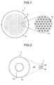
- FIG. 1 is a schematic cross-sectional view of a multi-core optical fiber to be manufactured by the manufacturing method according to the first embodiment.
- FIG. 1 is also a partially enlarged view of the cross section.
- a multi-core optical fiber 1 includes 10,000 cores 1a and a cladding 1b formed on an external periphery of the cores 1a.
- the multi-core optical fiber 1 is a solid type, and a refractive index of each of the cores 1a is higher than that of the cladding 1b.
- Each of the cores 1a is made of silica glass with Ge being added, for example, and the cladding 1b is made of pure silica glass not containing a dopant for adjusting a refractive index, or is made of silica glass with fluoride (F) being added.
- the diameter of the core 1a is about 10 micrometers, and a specific refractive-index difference between the core 1a and the cladding 1b is about 0.35%.
- a distance between centers of the cores 1a is set at about 50 micrometers (at least 40 micrometers), for example. An interference of light propagating in each of the cores 1a is then suppressed, and a crosstalk can be reduced to equal to or less than -30 decibels.
- a difference between centers of the cores 1a is at least 70 micrometers (80 micrometers, for example, considering a variation in distances between centers in a longitudinal direction). An interference of light propagating in each of the cores 1a is then suppressed, and a crosstalk can be reduced to equal to or less than -30 decibels.
- the multi-core optical fiber 1 includes 10,000 cores 1a, and has a possibility of achieving a remarkably large-capacity optical transmission that has never been able to be achieved.
- the manufacturing method according to the first embodiment as will be explained below can provide the multi-core optical fiber 1 more easily than the conventional method, and includes a preparing process, a first elongating process and a second elongating process.
- the manufacturing method will be explained below with respect to a case of using different kinds of cores 1a and setting a distance between centers of the cores 1a to 50 micrometers at least, and a case of using the same kind of cores 1a and setting a distance between centers of the cores 1a to 80 micrometers at least.
- FIG. 2 illustrates the preparing process.
- an optical fiber preform 2 is formed in an identical manner to that of manufacturing a normal solid optical fiber, by using a known method such as a vapor-phase axial deposition (VAD) method or a modified chemical vapor deposition (MCVD) method.
- the optical fiber preform 2 has a rod shape, and includes a core forming part 2a and a cladding forming part 2b formed on an external periphery of the core forming part 2a, as shown in a cross-sectional view in FIG. 2 .
- the core forming part 2a is a part where the core 1a is formed, and is made of the same material as that of the core 1a.
- the cladding forming part 2b is a part where the cladding 1b is formed, and is made of the same material as that of the cladding 1b.
- the ratio of the diameter between the core forming part 2a and the cladding forming part 2b is set at 1:5 or 1:8.
- the core forming part 2a is finally set such that the core 1 a has a diameter of about 10 micrometers by thermal extension, a distance between centers of adjacent cores 1a becomes about 50 micrometers or 80 micrometers. In this way, a distance between centers of adjacent cores 1a can be adjusted by the ratio of the diameter between the core forming part 2a and the cladding forming part 2b.
- plural different kinds (for example, three kinds) of optical fiber preforms 2 having the core forming parts 2a of mutually different refractive indexes are formed.
- the same kind or different kinds of optical fiber preforms 2 are then thermally elongated to form a first base material 3.
- This thermal extension can be performed by using a drawing device or a glass extension device used to manufacture an optical fiber.
- the first base material 3 has a diameter of about 1.0 millimeter to facilitate bundling of the first base materials 3 in a subsequent process.
- the first base material 3 includes a core forming part 3a and a cladding forming part 3b as shown in a cross-sectional view in FIG. 2 .
- the ratio of the diameter between the core forming part 3a and the cladding forming part 3b is substantially the same as the ratio of the diameter between the core forming part 2a and the cladding forming part 2b in the optical fiber preform 2.
- This first base material 3 is cut into pieces each having a length of 500 millimeters for example, at which the pieces can be easily bundled, whereby the same kind or different kinds of many first base materials 3 are prepared.
- FIG. 3 illustrates the first elongating process.
- a bundle of 100 first base materials 3 as prepared in the preparing process is inserted into a jacket tube 4a, thereby forming a first bundle 4 of the base materials.
- the 100 first base materials 3 are all of the same kind.
- the 100 first base materials 3 are those having been suitably selected from among different kinds of first base materials 3.
- the jacket tube 4a is made of the same material as that of the cladding 1b, for example, and the jacket tube 4a has such internal diameter that enables the jacket tube 4a to accommodate the 100 first base materials 3 by insertion.
- FIG. 3 illustrates only 90 first base materials 3 as arranged in a hexagonal close-packed structure (a triangular lattice shape), the remaining ten first base materials 3 are being inserted into gaps between the first base materials 3 and the jacket tube 4a.
- Rod-shaped filling members made of the same material as that of the cladding 1b, for example, are also inserted suitably into the remaining gaps between the first base materials 3 and the jacket tube 4a, thereby filling the gaps.
- the first bundle 4 is thermally elongated to form a second base material 5.
- the second base material 5 has a diameter of about 1.0 millimeter to facilitate bundling of the second base materials 5 in a subsequent process.
- This second base material 5 includes 100 core forming parts 5a and a cladding forming part 5b formed on an external periphery thereof, and has a cross-sectional structure identical to that of a normal multi-core optical fiber having 100 cores.
- This second base material 5 is cut into pieces each having a length of 500 millimeters for example, at which the pieces can be easily bundled, whereby many second base materials 5 are prepared.
- the second elongating process is substantially identical to the first elongating process.
- FIG. 4 illustrates the second elongating process.
- 100 second base materials 5 having been prepared in the first elongating process are suitably selected and are inserted into a jacket tube 6a, thereby forming a second bundle 6 of the base materials.
- the second bundle 6 contains 10,000 core forming parts 5a.
- the jacket tube 6a is also made of the same material as that of the cladding 1b, for example, and has such internal diameter that enables the jacket tube 6a to accommodate 100 second base materials 5 by insertion.
- FIG. 4 illustrates only 90 second base materials 5 as arranged in a triangular lattice shape, the remaining 10 second base materials 5 are being inserted into gaps between the second base materials 5 and the jacket tube 6a.
- Rod-shaped filling members made of the same material as that of the cladding 1b, for example, are also inserted suitably into the remaining gaps between the second base materials 5 and the jacket tube 6a, thereby filling the gaps.
- the second bundle 6 is then thermally elongated up until the point when the core forming part 5a has a diameter of about 10 micrometers. Accordingly, the multi-core optical fiber 1 including 10,000 cores 1a each having a diameter of 10 micrometers and having a distance between centers of the cores 1a at a desired value is formed. In this case, the multi-core optical fiber 1 has a diameter of 6 millimeters.
- the manufacturing method of the first embodiment of the present invention a process of thermally elongating a bundle of two or more base materials is performed two times to form the multi-core optical fiber 1. Therefore, the multi-core optical fiber 1 can be manufactured using base materials having a size at which the base materials can be easily handled in each of the processes. Consequently, a multi-core optical fiber including many cores such as 10,000 cores can be easily manufactured. At the same time, the cores 1a can be easily arranged at desired positions, and a length of the multi-core optical fiber 1 that can be manufactured at one time can be increased.
- FIG. 5 is a schematic cross-sectional view of a multi-core optical fiber to be manufactured by the manufacturing method according to the second embodiment.
- FIG. 5 is also a partially enlarged view of the cross section.
- a multi-core optical fiber 7 is an HF-type including 10,000 cores 7a as arranged in a triangular lattice shape and a cladding 7b formed on an external periphery of the cores 7a, and having a hole structure formed with holes 7c.
- the multi-core optical fiber 7 has the cores 7a and the cladding 7b made of the same material such as pure silica glass.
- Confinement of light in each of the cores 7a is achieved by decreasing an average refractive index of the cladding 7b by the holes 7c as arranged in a triangular lattice shape.
- a hole diameter d of each of the holes 7c is 2.15 micrometers, and a lattice constant A of a triangular lattice formed by the holes 7c is 5 micrometers. Therefore, d/A is 0.43, and an ESM characteristic can be achieved.
- a distance between centers of the cores 7a is at least about 50 micrometers. Accordingly, as disclosed in the document by K. Imamura et al., interference of light propagating in each of the cores 7a can be suppressed, and a crosstalk of over 1 kilometer can be suppressed to be equal to or less than -60 decibels.
- the multi-core optical fiber 7 includes 10,000 cores 7a and has the ESM characteristic, the multi-core optical fiber 7 can achieve an optical transmission in a larger transmission capacity than that of the multi-core optical fiber in the first embodiment.
- the manufacturing method according to the second embodiment as will be explained below can provide the multi-core optical fiber 7 more easily than the conventional methods.
- the manufacturing method according to the second embodiment includes a preparing process, a removing process, a first elongating process and a second elongating process.
- FIG. 6 illustrates the preparing process.
- a first base material is prepared by using a normal stack and draw method.
- 90 cladding forming members 8b as hollow capillary tubes to form the cladding 7b having the holes 7c are arranged in a triangular lattice shape and bundled around rod-shaped core forming members 8a to form the cores 7a. This bundle is inserted into a jacket tube 8c to form a preform 8. Diameters of the core forming members 8a and the cladding forming members 8b are set at about 1 millimeter at which these members can be easily bundled, respectively.
- the preform 8 is thermally elongated to form a first base material 9.
- the diameter of the first base material 9 is set at about 1.0 millimeter to facilitate bundling of the first base materials 9 in a subsequent process.
- the first base material 9 includes core forming parts 9a and a cladding forming part 9b having a hole structure formed on an external periphery of the core forming part 9a and with 90 holes 9c as arranged in a triangular shape, and has a cross-sectional structure identical to that of an HF.
- the first base material 9 is cut into pieces each having a length at which the pieces can be easily bundled to prepare many first base materials 9.
- FIG. 7 illustrates a removing process.
- a part region 9d at an outer edge of the cladding forming part 9b of the first base material 9 is removed by etching or polishing using an etching liquid such as hydrofluoric acid. Accordingly, the first base material 9 becomes a first base material 10 having a smaller diameter.
- FIG. 8 illustrates the first elongating process.
- a bundle of 100 first base materials 10 after the removing process is inserted into a jacket tube 11a to form a first bundle 11.
- the jacket tube 11a is made of the same material as that of the cladding 7b, for example.
- a rod-shaped filling member made of the same material as that of the cladding 7b, for example, is inserted suitably between the first base materials 10 and the jacket tube 11a to fill the gaps. Because each of the first base materials 10 has a smaller diameter than that of the first base material 9 after the removing process, the jacket tube 11a having a smaller internal diameter can be used.
- the first bundle 11 is then thermally elongated to form a second base material 12.
- the second base material 12 has a diameter of about 1.0 millimeter to facilitate bundling of the second base materials 12 in a subsequent process.
- the second base material 12 has a cross-sectional structure identical to that of an HF multi-core optical fiber having 100 cores. This second base material 12 is cut into pieces each having a length at which the pieces can be easily bundled, whereby many second base materials 12 can be prepared.
- a bundle of 100 second base materials 12 is inserted into a jacket tube, and the second elongating process identical to the first elongating process is performed, thereby forming the multi-core optical fiber 7 including 10,000 cores 7a.
- a multi-core optical fiber can be manufactured using base materials having a size at which the base materials can be easily handled in each of the processes, in a similar manner to that of the first embodiment. Therefore, a multi-core optical fiber including many cores such as 10,000 cores can be manufactured more easily, and a length of the multi-core optical fiber 1 that can be manufactured at one time can be increased.
- the first base material 9 is prepared by the stack and draw method in the preparing process
- the drilling method and a sol-gel method conventionally used to manufacture HFs can also be used.
- the removing process is performed only to the first base material 9, the removing process can also be performed to the second base material 12, or can be performed only to the second base material 12. In the first embodiment, the removing process can also be performed to at least one of the first base material 3 and the second base material 5.
- the first base materials 9 are bundled in the first elongating process of the second embodiment, for example, a glass part at an outer edge of the first base materials 9 is surrounded by holes of other first base materials 9.
- this glass part is surrounded by holes and has a function of propagating light like an original core, in some cases.
- the cross-sectional area of this glass part becomes small, and this risk is decreased.
- the cross-sectional area of the glass part is decreased to be in an external shape along a hexagonal region arranged with the holes 9c in the first base materials 9.
- the removing process is performed after the elongating process and a region at an outer edge corresponding to the jacket tube is removed.
- the diameter of each of the base materials there is no particular limit to the diameter of each of the base materials as long as the base material can be easily handled without being easily broken.
- the diameter is equal to or greater than 400 micrometers to facilitate the handling.
- cores and holes of a multi-core optical fiber to be manufactured are arranged in a triangular lattice shape, other arrangements can also be applied for the manufacturing.
- the number of cores is not limited to 10,000, and the number of the first and second materials to be bundled is not particularly limited.
- the second elongating process is performed one time, the second elongating process can be performed two times and a bundle of the second materials can be thermally elongated up until the point when a multi-core optical fiber is formed in the last second elongating process. With this arrangement, a multi-core optical fiber including a larger number of cores can be easily manufactured.
- the first base material includes one core forming part
- the first base material can include plural core forming parts.
- all materials to constitute the first bundle are the first base materials
- all materials to constitute the second bundle are the second base materials.
- the present invention is not limited to such arrangements, and it is sufficient that the first bundle and the second bundle include at least one first base material and one second base material, respectively.
- first base material having a core forming part and 90 holes like the first base material in the second embodiment, and 99 first base materials each in a structure having no core forming part and having 91 holes formed at a position of a core forming part are prepared. These first base materials are bundled to form a first bundle, and this first bundle is thermally elongated to form a second base material.
- 100 second base materials are bundled to form a second bundle, and this second bundle is thermally elongated to manufacture a multi-core optical fiber.
- an HF multi-core optical fiber including 100 cores, each core being surrounded by at least 9,099 holes, can be obtained.
- a second bundle is formed by bundling one second base material and 99 second base materials each in a structure having no core forming part and having 9,100 holes formed at a position of a core forming part.
- An optical fiber or a multi-core optical fiber having one core having a considerably large number of cores like this example can be manufactured remarkably easily by the present invention, although it is considerably difficult to achieve this by the conventional methods.
- the first bundle When the first bundle is configured by all first base materials, a distance between centers of the core forming parts becomes the same for all core forming parts. However, when any one of the first base materials of the first bundle is replaced with a material having no core forming part, a distance between centers of the core forming parts can be increased. When the first bundle having a part of the first base materials replaced with other base materials is used in this way, a multi-core optical fiber having a different distance between centers of the cores can be easily manufactured.
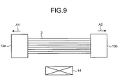
- FIG. 9 is another example of the elongating process. As shown in FIG. 9 , instead of the first elongating process in the manufacturing method according to the first embodiment, the first base materials 3 are bundled, and both ends of this bundle are held by holding tools 13a and 13b.
- the holding tools 13a and 13b are displaced such that the holding tools 13a and 13b are separated to directions of an arrow A1 and an arrow A2, respectively, thereby elongating the bundle of the first base materials 3, while heating a side surface of the bundle of the first base materials 3 by a heater 14.
- an optical fiber having a fine and complex cross-sectional structure can be more easily manufactured because the optical fiber can be manufactured using base materials having a size with better handleability.
Landscapes
- Chemical & Material Sciences (AREA)
- Engineering & Computer Science (AREA)
- Physics & Mathematics (AREA)
- General Life Sciences & Earth Sciences (AREA)
- Life Sciences & Earth Sciences (AREA)
- Optics & Photonics (AREA)
- Geochemistry & Mineralogy (AREA)
- Manufacturing & Machinery (AREA)
- Materials Engineering (AREA)
- Organic Chemistry (AREA)
- Crystallography & Structural Chemistry (AREA)
- General Physics & Mathematics (AREA)
- Manufacture, Treatment Of Glass Fibers (AREA)
- Optical Fibers, Optical Fiber Cores, And Optical Fiber Bundles (AREA)
Abstract
An optical fiber manufacturing method comprises preparing first base materials (3, 9, 10) each of which includes at least one core forming part to form a core (1a, 7a) and a cladding forming part to form a cladding (1b, 7b); performing a first elongating to form second base materials (5, 12) by forming a first bundle (4, 11) by bundling two or more base materials including at least one of the first base materials having been prepared at the preparing and by thermally elongating the first bundle; and performing a second elongating at least once to form a second bundle (6) by bundling two or more base materials including at least one of the second base materials and by thermally elongating the second bundle, wherein the second bundle is thermally elongated up until the point when the optical fiber (1, 7) is formed at the second elongating.
Description
- This application is based upon and claims the benefit of priority from the prior Japanese Patent Application No.
2009-246746, filed on October 27, 2009 - The present invention relates to an optical fiber manufacturing method.
- A multi-core optical fiber (MCF) is a novel optical fiber including plural cores in one optical fiber, and it is capable of having many cores provided in a small space. The multi-core optical fiber is expected to achieve a large-capacity image transmission and a new optical propagation such as a spatial multiplexing transmission. Particularly, a type of a multi-core optical fiber suppressing an optical interference between cores can achieve two times the original transmission capacity when the core number doubles, and three times the original transmission capacity when the core number triples, for example. Therefore, this can become a key technique for a large-capacity transmission in the future. Accordingly, techniques of multi-core optical fibers used as optical transmission paths have been widely studied.
- There is a type of multi-core optical fiber that confines light into cores by adding germanium (Ge) to cores and by increasing a refractive index of cores to be higher than that of a cladding (hereinafter, where appropriate, "solid multi-core optical fiber"), like normal optical fibers. For example, a document by M. Koshiba et al. (IEICE Electron Express 2009, Vol. 6, No. 2, pp 98-103) discloses a solid multi-core optical fiber having cores, of which refractive index is slightly different from that of a clad, arranged in a cladding with an external diameter of 125 micrometers. Meanwhile, there is a type of multi-core optical fiber that is called "holey fiber (HF)". The holey fiber is an optical fiber that propagates light by confining the light using a principle of a total reflection by decreasing an average refractive index of a clad, by regularly arranging holes in the cladding and forming a hole structure. The holey fiber can achieve a special characteristic such as an abnormal dispersion in an endlessly single mode (ESM) or in a short wavelength which a conventional optical fiber cannot achieve, by using holes to control a refractive index. For example, a document by K. Imamura et al. (OFC2009-OTuC3) discloses an HF multi-core optical fiber capable of achieving an optical transmission over 100 kilometers in a wavelength region of 500 nanometers to 1,620 nanometers.
- As manufacturing methods of a multi-core optical fiber, there are a stack and draw method and a drilling method used as conventional manufacturing methods of holey fibers. The stack and draw method arranges a hollow glass capillary tube to form a cladding having holes around a solid glass rod to form cores in a case of an HF-type, and arranges a glass rod to form a cladding having a lower refractive index than that of cores around a solid glass rod to form cores in a case of a solid type. The hollow glass capillary tube or the glass rod is inserted into a jacket tube, and the jacket tube is thermally elongated to form an optical fiber preform. According to the drilling method, holes are formed with a drill in a rod-shaped base material made of glass, and the holes are arranged in a cladding in the case of the HF-type, and a glass rod to form cores is inserted into the holes in the case of the solid type, thereby forming an optical fiber preform, respectively.
- However, according to the stack and draw method, the drilling method or the like, there is a problem in that manufacturing of a multi-core optical fiber becomes increasingly difficult when a cross-sectional structure of the cores becomes minute and complex along with an increase in the number of cores. When a holey fiber having one core is manufactured, it becomes increasingly difficult to manufacture an optical fiber as a cross-sectional structure of the core becomes minute and complex along with the increase in the number of holes.
- The present invention has been achieved in view of the above problems, and an object of the present invention is to provide an optical fiber manufacturing method capable of more easily manufacturing an optical fiber having a minute and complex cross-sectional structure.
- It is an object of the present invention to at least partially solve the problems in the conventional technology.
- In accordance with one aspect of the present invention, an optical fiber manufacturing method comprises preparing first base materials (3, 9, 10) each of which includes at least one core forming part to form a core (1a, 7a) and a cladding forming part to form a cladding (1b, 7b); performing a first elongating to form second base materials (5, 12) by forming a first bundle (4, 11) by bundling two or more base materials including at least one of the first base materials having been prepared at the preparing and by thermally elongating the first bundle; and performing a second elongating at least once to form a second bundle (6) by bundling two or more base materials including at least one of the second base materials and by thermally elongating the second bundle, wherein the second bundle is thermally elongated up until the point when the optical fiber (1, 7) is formed at the second elongating.
- The above and other objects, features, advantages and technical and industrial significance of this invention will be better understood by reading the following detailed description of presently preferred embodiments of the invention, when considered in connection with the accompanying drawings.
-
-
FIG. 1 is a schematic cross-sectional view of a multi-core optical fiber to be manufactured by a manufacturing method according to a first embodiment of the present invention; -
FIG. 2 is a diagram depicting a preparing process in the first embodiment; -
FIG. 3 is a diagram depicting a first elongating process in the first embodiment; -
FIG. 4 is a diagram depicting a second elongating process in the first embodiment; -
FIG. 5 is a schematic cross-sectional view of a multi-core optical fiber to be manufactured by a manufacturing method according to a second embodiment of the present invention; -
FIG. 6 is a diagram depicting a preparing process in the second embodiment; -
FIG. 7 is a diagram depicting a removing process in the second embodiment; -
FIG. 8 is a diagram depicting a first elongating process in the second embodiment; and -
FIG. 9 is a diagram showing another example of the elongating process in the second embodiment. - Exemplary embodiments of an optical fiber manufacturing method according to the present invention will be explained below in detail with reference to the accompanying drawings. The present invention is not limited to the embodiments. In addition, the same reference numerals are denoted to like or corresponding constituent elements in the drawings.
- A manufacturing method of a multi-core optical fiber according to a first embodiment of the present invention will be explained first.
FIG. 1 is a schematic cross-sectional view of a multi-core optical fiber to be manufactured by the manufacturing method according to the first embodiment.FIG. 1 is also a partially enlarged view of the cross section. As shown inFIG. 1 , a multi-core optical fiber 1 includes 10,000cores 1a and a cladding 1b formed on an external periphery of thecores 1a. The multi-core optical fiber 1 is a solid type, and a refractive index of each of thecores 1a is higher than that of thecladding 1b. Each of thecores 1a is made of silica glass with Ge being added, for example, and the cladding 1b is made of pure silica glass not containing a dopant for adjusting a refractive index, or is made of silica glass with fluoride (F) being added. The diameter of thecore 1a is about 10 micrometers, and a specific refractive-index difference between thecore 1a and thecladding 1b is about 0.35%. When mutual specific refractive indexes of thecores 1a are to be slightly differentiated (that is, when different kinds ofcores 1a are being used) in the multi-core optical fiber 1 as described in the document by M. Koshiba et al., a distance between centers of thecores 1a is set at about 50 micrometers (at least 40 micrometers), for example. An interference of light propagating in each of thecores 1a is then suppressed, and a crosstalk can be reduced to equal to or less than -30 decibels. On the other hand, when the same kind ofcores 1 a having mutually the same specific refractive-indexes are used, a difference between centers of thecores 1a is at least 70 micrometers (80 micrometers, for example, considering a variation in distances between centers in a longitudinal direction). An interference of light propagating in each of thecores 1a is then suppressed, and a crosstalk can be reduced to equal to or less than -30 decibels. - The multi-core optical fiber 1 includes 10,000
cores 1a, and has a possibility of achieving a remarkably large-capacity optical transmission that has never been able to be achieved. The manufacturing method according to the first embodiment as will be explained below can provide the multi-core optical fiber 1 more easily than the conventional method, and includes a preparing process, a first elongating process and a second elongating process. The manufacturing method will be explained below with respect to a case of using different kinds ofcores 1a and setting a distance between centers of thecores 1a to 50 micrometers at least, and a case of using the same kind ofcores 1a and setting a distance between centers of thecores 1a to 80 micrometers at least. - The preparing process will be explained first.
FIG. 2 illustrates the preparing process. First, anoptical fiber preform 2 is formed in an identical manner to that of manufacturing a normal solid optical fiber, by using a known method such as a vapor-phase axial deposition (VAD) method or a modified chemical vapor deposition (MCVD) method. Theoptical fiber preform 2 has a rod shape, and includes acore forming part 2a and acladding forming part 2b formed on an external periphery of thecore forming part 2a, as shown in a cross-sectional view inFIG. 2 . Thecore forming part 2a is a part where thecore 1a is formed, and is made of the same material as that of thecore 1a. On the other hand, thecladding forming part 2b is a part where the cladding 1b is formed, and is made of the same material as that of thecladding 1b. The ratio of the diameter between thecore forming part 2a and thecladding forming part 2b is set at 1:5 or 1:8. When thecore forming part 2a is finally set such that thecore 1 a has a diameter of about 10 micrometers by thermal extension, a distance between centers ofadjacent cores 1a becomes about 50 micrometers or 80 micrometers. In this way, a distance between centers ofadjacent cores 1a can be adjusted by the ratio of the diameter between thecore forming part 2a and thecladding forming part 2b. In manufacturing the multi-core optical fiber 1 using different kinds ofcores 1a, plural different kinds (for example, three kinds) of optical fiber preforms 2 having thecore forming parts 2a of mutually different refractive indexes are formed. - The same kind or different kinds of optical fiber preforms 2 are then thermally elongated to form a
first base material 3. This thermal extension can be performed by using a drawing device or a glass extension device used to manufacture an optical fiber. In this case, thefirst base material 3 has a diameter of about 1.0 millimeter to facilitate bundling of thefirst base materials 3 in a subsequent process. Thefirst base material 3 includes acore forming part 3a and acladding forming part 3b as shown in a cross-sectional view inFIG. 2 . The ratio of the diameter between thecore forming part 3a and thecladding forming part 3b is substantially the same as the ratio of the diameter between thecore forming part 2a and thecladding forming part 2b in theoptical fiber preform 2. Thisfirst base material 3 is cut into pieces each having a length of 500 millimeters for example, at which the pieces can be easily bundled, whereby the same kind or different kinds of manyfirst base materials 3 are prepared. - The first elongating process will be explained next.
FIG. 3 illustrates the first elongating process. First, as shown inFIG. 3 , a bundle of 100first base materials 3 as prepared in the preparing process is inserted into ajacket tube 4a, thereby forming afirst bundle 4 of the base materials. When the multi-core optical fiber 1 using the same kind ofcores 1a is manufactured, the 100first base materials 3 are all of the same kind. On the other hand, when the multi-core optical fiber 1 using different kinds ofcores 1a is manufactured, the 100first base materials 3 are those having been suitably selected from among different kinds offirst base materials 3. Thejacket tube 4a is made of the same material as that of thecladding 1b, for example, and thejacket tube 4a has such internal diameter that enables thejacket tube 4a to accommodate the 100first base materials 3 by insertion. AlthoughFIG. 3 illustrates only 90first base materials 3 as arranged in a hexagonal close-packed structure (a triangular lattice shape), the remaining tenfirst base materials 3 are being inserted into gaps between thefirst base materials 3 and thejacket tube 4a. Rod-shaped filling members made of the same material as that of thecladding 1b, for example, are also inserted suitably into the remaining gaps between thefirst base materials 3 and thejacket tube 4a, thereby filling the gaps. Next, thefirst bundle 4 is thermally elongated to form asecond base material 5. In this case, thesecond base material 5 has a diameter of about 1.0 millimeter to facilitate bundling of thesecond base materials 5 in a subsequent process. Thissecond base material 5 includes 100core forming parts 5a and acladding forming part 5b formed on an external periphery thereof, and has a cross-sectional structure identical to that of a normal multi-core optical fiber having 100 cores. Thissecond base material 5 is cut into pieces each having a length of 500 millimeters for example, at which the pieces can be easily bundled, whereby manysecond base materials 5 are prepared. - The second elongating process will be explained next. The second elongating process is substantially identical to the first elongating process.
FIG. 4 illustrates the second elongating process. As shown inFIG. 4 , 100second base materials 5 having been prepared in the first elongating process are suitably selected and are inserted into ajacket tube 6a, thereby forming asecond bundle 6 of the base materials. As a result, thesecond bundle 6 contains 10,000core forming parts 5a. Thejacket tube 6a is also made of the same material as that of thecladding 1b, for example, and has such internal diameter that enables thejacket tube 6a to accommodate 100second base materials 5 by insertion. AlthoughFIG. 4 illustrates only 90second base materials 5 as arranged in a triangular lattice shape, the remaining 10second base materials 5 are being inserted into gaps between thesecond base materials 5 and thejacket tube 6a. Rod-shaped filling members made of the same material as that of thecladding 1b, for example, are also inserted suitably into the remaining gaps between thesecond base materials 5 and thejacket tube 6a, thereby filling the gaps. - The
second bundle 6 is then thermally elongated up until the point when thecore forming part 5a has a diameter of about 10 micrometers. Accordingly, the multi-core optical fiber 1 including 10,000cores 1a each having a diameter of 10 micrometers and having a distance between centers of thecores 1a at a desired value is formed. In this case, the multi-core optical fiber 1 has a diameter of 6 millimeters. - When a multi-core optical fiber including 10,000 cores is manufactured by using the conventional stack and draw method, 10,000 base materials to form the cores are necessary to be inserted into a jacket tube having a limited internal diameter. Therefore, the diameter of each of the base materials needs to be considerably small. Consequently, the base materials are easily damaged or broken, and become difficult to handle. Considering breaking of the base materials, a thin base material cannot have a large length. Therefore, a bundle of the base materials to be elongated cannot have a large length, and a length of a multi-core optical fiber that can be manufactured at one time cannot be increased. When a large number of base materials are used to form the cores, it becomes difficult to arrange the core materials all at desired positions within the jacket tube and to maintain the arrangement. Consequently, a positional deviation of the cores can occur easily, and it becomes difficult to set a distance between centers of the cores at a desired value.
- On the other hand, according to the manufacturing method of the first embodiment of the present invention, a process of thermally elongating a bundle of two or more base materials is performed two times to form the multi-core optical fiber 1. Therefore, the multi-core optical fiber 1 can be manufactured using base materials having a size at which the base materials can be easily handled in each of the processes. Consequently, a multi-core optical fiber including many cores such as 10,000 cores can be easily manufactured. At the same time, the
cores 1a can be easily arranged at desired positions, and a length of the multi-core optical fiber 1 that can be manufactured at one time can be increased. - A manufacturing method of a multi-core optical fiber according to a second embodiment of the present invention will be explained next.
FIG. 5 is a schematic cross-sectional view of a multi-core optical fiber to be manufactured by the manufacturing method according to the second embodiment.FIG. 5 is also a partially enlarged view of the cross section. As shown inFIG. 5 , a multi-coreoptical fiber 7 is an HF-type including 10,000cores 7a as arranged in a triangular lattice shape and acladding 7b formed on an external periphery of thecores 7a, and having a hole structure formed withholes 7c. The multi-coreoptical fiber 7 has thecores 7a and thecladding 7b made of the same material such as pure silica glass. Confinement of light in each of thecores 7a is achieved by decreasing an average refractive index of thecladding 7b by theholes 7c as arranged in a triangular lattice shape. A hole diameter d of each of theholes 7c is 2.15 micrometers, and a lattice constant A of a triangular lattice formed by theholes 7c is 5 micrometers. Therefore, d/A is 0.43, and an ESM characteristic can be achieved. A distance between centers of thecores 7a is at least about 50 micrometers. Accordingly, as disclosed in the document by K. Imamura et al., interference of light propagating in each of thecores 7a can be suppressed, and a crosstalk of over 1 kilometer can be suppressed to be equal to or less than -60 decibels. - Because the multi-core
optical fiber 7 includes 10,000cores 7a and has the ESM characteristic, the multi-coreoptical fiber 7 can achieve an optical transmission in a larger transmission capacity than that of the multi-core optical fiber in the first embodiment. The manufacturing method according to the second embodiment as will be explained below can provide the multi-coreoptical fiber 7 more easily than the conventional methods. The manufacturing method according to the second embodiment includes a preparing process, a removing process, a first elongating process and a second elongating process. - The preparing process in the manufacturing method according to the second embodiment will be explained first.
FIG. 6 illustrates the preparing process. In the preparing process, a first base material is prepared by using a normal stack and draw method. As shown inFIG. 6 , 90cladding forming members 8b as hollow capillary tubes to form thecladding 7b having theholes 7c are arranged in a triangular lattice shape and bundled around rod-shapedcore forming members 8a to form thecores 7a. This bundle is inserted into ajacket tube 8c to form apreform 8. Diameters of thecore forming members 8a and thecladding forming members 8b are set at about 1 millimeter at which these members can be easily bundled, respectively. A rod-shaped filling member made of the same material as that of thecladding 7b, for example, is inserted suitably between thecladding forming members 8b and thejacket tube 8c to fill the gaps. Thepreform 8 is thermally elongated to form afirst base material 9. The diameter of thefirst base material 9 is set at about 1.0 millimeter to facilitate bundling of thefirst base materials 9 in a subsequent process. Thefirst base material 9 includescore forming parts 9a and acladding forming part 9b having a hole structure formed on an external periphery of thecore forming part 9a and with 90holes 9c as arranged in a triangular shape, and has a cross-sectional structure identical to that of an HF. Thefirst base material 9 is cut into pieces each having a length at which the pieces can be easily bundled to prepare manyfirst base materials 9. - The removing process will be explained next.
FIG. 7 illustrates a removing process. In this removing process, apart region 9d at an outer edge of thecladding forming part 9b of thefirst base material 9 is removed by etching or polishing using an etching liquid such as hydrofluoric acid. Accordingly, thefirst base material 9 becomes afirst base material 10 having a smaller diameter. - The first elongating process will be explained next.
FIG. 8 illustrates the first elongating process. As shown inFIG. 8 , a bundle of 100first base materials 10 after the removing process is inserted into ajacket tube 11a to form afirst bundle 11. Thejacket tube 11a is made of the same material as that of thecladding 7b, for example. A rod-shaped filling member made of the same material as that of thecladding 7b, for example, is inserted suitably between thefirst base materials 10 and thejacket tube 11a to fill the gaps. Because each of thefirst base materials 10 has a smaller diameter than that of thefirst base material 9 after the removing process, thejacket tube 11a having a smaller internal diameter can be used. - The
first bundle 11 is then thermally elongated to form asecond base material 12. In this case, thesecond base material 12 has a diameter of about 1.0 millimeter to facilitate bundling of thesecond base materials 12 in a subsequent process. Thesecond base material 12 has a cross-sectional structure identical to that of an HF multi-core optical fiber having 100 cores. Thissecond base material 12 is cut into pieces each having a length at which the pieces can be easily bundled, whereby manysecond base materials 12 can be prepared. A bundle of 100second base materials 12 is inserted into a jacket tube, and the second elongating process identical to the first elongating process is performed, thereby forming the multi-coreoptical fiber 7 including 10,000cores 7a. - According to the manufacturing method of the second embodiment, a multi-core optical fiber can be manufactured using base materials having a size at which the base materials can be easily handled in each of the processes, in a similar manner to that of the first embodiment. Therefore, a multi-core optical fiber including many cores such as 10,000 cores can be manufactured more easily, and a length of the multi-core optical fiber 1 that can be manufactured at one time can be increased.
- In the second embodiment, although the
first base material 9 is prepared by the stack and draw method in the preparing process, the drilling method and a sol-gel method conventionally used to manufacture HFs can also be used. - In the second embodiment, although the removing process is performed only to the
first base material 9, the removing process can also be performed to thesecond base material 12, or can be performed only to thesecond base material 12. In the first embodiment, the removing process can also be performed to at least one of thefirst base material 3 and thesecond base material 5. - When the
first base materials 9 are bundled in the first elongating process of the second embodiment, for example, a glass part at an outer edge of thefirst base materials 9 is surrounded by holes of otherfirst base materials 9. As a result, in a finally-manufactured multi-core optical fiber, this glass part is surrounded by holes and has a function of propagating light like an original core, in some cases. In this case, there is a risk of crosstalk between cores of the multi-core optical fiber aggravating and power of light propagating in the cores being absorbed by the glass part. However, in the first embodiment, because thefirst base materials 10 having removed thepart region 9d at an outer edge of thefirst base materials 9 are used in the removing process, a cross-sectional area of this glass part becomes small, and this risk is decreased. Preferably, in the removing process, the cross-sectional area of the glass part is decreased to be in an external shape along a hexagonal region arranged with theholes 9c in thefirst base materials 9. - In the elongating processes of the first and second embodiments, when a jacket tube having a refractive index different from that of a cladding of a multi-core optical fiber finally formed is used, there is a risk that a remaining part of the jacket tube causes a negative influence on an optical transmission characteristic of the multi-core optical fiber. In this case, it is preferable that the removing process is performed after the elongating process and a region at an outer edge corresponding to the jacket tube is removed.
- In each of the processes of the first and second embodiments, there is no particular limit to the diameter of each of the base materials as long as the base material can be easily handled without being easily broken. Preferably, the diameter is equal to or greater than 400 micrometers to facilitate the handling.
- In the first and second embodiments, although cores and holes of a multi-core optical fiber to be manufactured are arranged in a triangular lattice shape, other arrangements can also be applied for the manufacturing. The number of cores is not limited to 10,000, and the number of the first and second materials to be bundled is not particularly limited. In the first and second embodiments, although the second elongating process is performed one time, the second elongating process can be performed two times and a bundle of the second materials can be thermally elongated up until the point when a multi-core optical fiber is formed in the last second elongating process. With this arrangement, a multi-core optical fiber including a larger number of cores can be easily manufactured.
- In the first and second embodiments, although the first base material includes one core forming part, the first base material can include plural core forming parts. In the first and second embodiments, all materials to constitute the first bundle are the first base materials, and all materials to constitute the second bundle are the second base materials. However, the present invention is not limited to such arrangements, and it is sufficient that the first bundle and the second bundle include at least one first base material and one second base material, respectively.
- The above arrangement can be explained by a specific example. For instance, one first base material having a core forming part and 90 holes like the first base material in the second embodiment, and 99 first base materials each in a structure having no core forming part and having 91 holes formed at a position of a core forming part are prepared. These first base materials are bundled to form a first bundle, and this first bundle is thermally elongated to form a second base material. This second base material has one core forming part and a cladding forming part having 9,099 (=90+91×99) holes.
- Further, 100 second base materials are bundled to form a second bundle, and this second bundle is thermally elongated to manufacture a multi-core optical fiber. As a result, an HF multi-core optical fiber including 100 cores, each core being surrounded by at least 9,099 holes, can be obtained. Further, a second bundle is formed by bundling one second base material and 99 second base materials each in a structure having no core forming part and having 9,100 holes formed at a position of a core forming part. When this second bundle is thermally elongated to form an optical fiber, an HF optical fiber having each core surrounded by 909,999 (=9,099+9,100x99) holes can be obtained. An optical fiber or a multi-core optical fiber having one core having a considerably large number of cores like this example can be manufactured remarkably easily by the present invention, although it is considerably difficult to achieve this by the conventional methods.
- When the first bundle is configured by all first base materials, a distance between centers of the core forming parts becomes the same for all core forming parts. However, when any one of the first base materials of the first bundle is replaced with a material having no core forming part, a distance between centers of the core forming parts can be increased. When the first bundle having a part of the first base materials replaced with other base materials is used in this way, a multi-core optical fiber having a different distance between centers of the cores can be easily manufactured.
- In the first and second embodiments, although the base materials are inserted into the jacket tube and this jacket tube is thermally elongated in each of the elongating processes, the base materials do not need to be inserted into the jacket tube.
FIG. 9 is another example of the elongating process. As shown inFIG. 9 , instead of the first elongating process in the manufacturing method according to the first embodiment, thefirst base materials 3 are bundled, and both ends of this bundle are held by holdingtools holding tools holding tools first base materials 3, while heating a side surface of the bundle of thefirst base materials 3 by aheater 14. - According to the present invention, an optical fiber having a fine and complex cross-sectional structure can be more easily manufactured because the optical fiber can be manufactured using base materials having a size with better handleability.
- Although the invention has been described with respect to specific embodiments for a complete and clear disclosure, the appended claims are not to be thus limited but are to be construed as embodying all modifications and alternative constructions that may occur to one skilled in the art that fairly fall within the basic teaching herein set forth.
Claims (8)
- An optical fiber manufacturing method comprising:preparing first base materials (3, 9, 10) each of which includes at least one core forming part to form a core (1a, 7a) and a cladding forming part to form a cladding (1b, 7b);performing a first elongating to form second base materials (5, 12) by forming a first bundle (4, 11) by bundling two or more base materials including at least one of the first base materials having been prepared at the preparing and by thermally elongating the first bundle; andperforming a second elongating at least once to form a second bundle (6) by bundling two or more base materials including at least one of the second base materials and by thermally elongating the second bundle, whereinthe second bundle is thermally elongated up until the point when the optical fiber (1, 7) is formed at the second elongating.
- The optical fiber manufacturing method according to claim 1, wherein the second elongating is performed two or more times, and the second bundle is thermally elongated up until the point when the optical fiber is formed at the last second elongating.
- The optical fiber manufacturing method according to claim 1, wherein the first bundle or the second bundle is inserted into a jacket tube (4a, 6a, 8c, 11 a) and the jacket tube is thermally elongated at the first elongating or the second elongating.
- The optical fiber manufacturing method according to claim 3, wherein the jacket tube is made of the same material as that of the cladding.
- The optical fiber manufacturing method according to claim 1, further comprising removing of a part of a region at an outer edge (9d) of the first base material or the second base material.
- The optical fiber manufacturing method according to claim 1, wherein a diameter of the first base material or the second base material is set to be equal to or greater than 400 micrometers.
- The optical fiber manufacturing method according to claim 1, wherein the first base material in which a refractive index of the core forming part is higher than a refractive index of the cladding forming part is prepared at the preparing.
- The optical fiber manufacturing method according to claim 1, wherein the first base material having a hole (7c, 9c) structure in the cladding forming part is prepared at the preparing.
Applications Claiming Priority (1)
| Application Number | Priority Date | Filing Date | Title |
|---|---|---|---|
| JP2009246746A JP2011095332A (en) | 2009-10-27 | 2009-10-27 | Optical fiber manufacturing method |
Publications (1)
| Publication Number | Publication Date |
|---|---|
| EP2320256A1 true EP2320256A1 (en) | 2011-05-11 |
Family
ID=43446418
Family Applications (1)
| Application Number | Title | Priority Date | Filing Date |
|---|---|---|---|
| EP10251745A Withdrawn EP2320256A1 (en) | 2009-10-27 | 2010-10-06 | Optical fiber manufacturing method |
Country Status (3)
| Country | Link |
|---|---|
| US (1) | US20110094269A1 (en) |
| EP (1) | EP2320256A1 (en) |
| JP (1) | JP2011095332A (en) |
Cited By (4)
| Publication number | Priority date | Publication date | Assignee | Title |
|---|---|---|---|---|
| WO2019232394A1 (en) * | 2018-06-01 | 2019-12-05 | Corning Incorporated | Microstructured glass articles with at least 100 core elements and methods for forming the same |
| US11377384B2 (en) | 2017-01-19 | 2022-07-05 | University Of Bath | Method of making an imaging fibre apparatus and optical fibre apparatus with different core |
| WO2022236305A1 (en) | 2021-05-06 | 2022-11-10 | Heraeus Quartz North America Llc | Process of makiin multi-core fiber preform by integrating core rods and cladding cylinder |
| WO2023137269A1 (en) | 2022-01-14 | 2023-07-20 | Heraeus Quartz North America Llc | Reduction of multi-core fiber preform geometric distortion |
Families Citing this family (11)
| Publication number | Priority date | Publication date | Assignee | Title |
|---|---|---|---|---|
| WO2011115146A1 (en) | 2010-03-16 | 2011-09-22 | 古河電気工業株式会社 | Holey fiber |
| JP5619516B2 (en) | 2010-08-04 | 2014-11-05 | 古河電気工業株式会社 | Optical fiber |
| JP5598488B2 (en) * | 2012-03-08 | 2014-10-01 | トヨタ自動車株式会社 | Manufacturing method of fluoride image guide |
| JP6057340B2 (en) * | 2013-08-27 | 2017-01-11 | 日本電信電話株式会社 | Multi-core optical fiber |
| US9828284B2 (en) * | 2014-03-28 | 2017-11-28 | Ut-Battelle, Llc | Thermal history-based etching |
| NZ749957A (en) | 2016-07-15 | 2020-03-27 | Light Field Lab Inc | Selective propagation of energy in light field and holographic waveguide arrays |
| EP3737980A4 (en) | 2018-01-14 | 2021-11-10 | Light Field Lab, Inc. | SYSTEMS AND METHODS FOR LOCATING TRANSVERSE ENERGY IN ENERGY RELAYS USING ORDERED STRUCTURES |
| JP7495299B2 (en) * | 2019-08-27 | 2024-06-04 | 古河電気工業株式会社 | Multicore fiber and its manufacturing method |
| JP2022020908A (en) * | 2020-07-21 | 2022-02-02 | 古河電気工業株式会社 | Multi-core fiber and manufacturing method thereof, cable, and communication system |
| EP3945351A1 (en) * | 2020-07-30 | 2022-02-02 | AIP Leibniz-Institut für Astrophysik | Apparatus for guiding light from an input side to an output side |
| JP7589743B2 (en) * | 2020-10-22 | 2024-11-26 | 日本電信電話株式会社 | Ultraviolet light irradiation system and method |
Citations (11)
| Publication number | Priority date | Publication date | Assignee | Title |
|---|---|---|---|---|
| US6041154A (en) * | 1994-04-08 | 2000-03-21 | Olympus Optical Co., Ltd. | Image fiber and method of fabricating the same |
| US6301420B1 (en) * | 1998-05-01 | 2001-10-09 | The Secretary Of State For Defence In Her Britannic Majesty's Government Of The United Kingdom Of Great Britain And Northern Ireland | Multicore optical fibre |
| WO2002026648A1 (en) * | 2000-09-11 | 2002-04-04 | Schott Communications Technologies, Inc. | Multi-component all glass photonic band-gap fiber |
| US20030056546A1 (en) * | 2001-09-18 | 2003-03-27 | Claus Richard O. | Photonic crystal materials and devices |
| WO2004102239A1 (en) * | 2003-05-09 | 2004-11-25 | Forschungsverbund Berlin E.V. | Arrangement for the production of optical multiwave signals and multisignal source |
| WO2006119334A2 (en) * | 2005-05-03 | 2006-11-09 | The Arizona Board Of Regents On Behalf Of The University Of Arizona | Microstructured optical fibers and manufacturing methods thereof |
| US20070266738A1 (en) * | 2006-05-19 | 2007-11-22 | Michael Thomas Gallagher | Method of making an optical fiber |
| EP1942321A1 (en) * | 2007-01-03 | 2008-07-09 | Danmarks Tekniske Universitet | A spectrometer with a plurality of light guides having a bandpass transmission spectrum |
| WO2008098338A1 (en) * | 2007-02-15 | 2008-08-21 | Institut National D'optique | Archimedean-lattice microstructured optical fiber |
| GB2457948A (en) * | 2008-02-29 | 2009-09-02 | Sumitomo Electric Industries | Photonic bandgap fibre |
| JP2009246746A (en) | 2008-03-31 | 2009-10-22 | Mitsubishi Electric Corp | Spiral antenna |
Family Cites Families (6)
| Publication number | Priority date | Publication date | Assignee | Title |
|---|---|---|---|---|
| JPS59165005A (en) * | 1983-03-11 | 1984-09-18 | Sumitomo Electric Ind Ltd | Image fiber manufacturing method |
| US5735927A (en) * | 1996-06-28 | 1998-04-07 | The United States Of America As Represented By The Secretary Of The Navy | Method for producing core/clad glass optical fiber preforms using hot isostatic pressing |
| GB0614272D0 (en) * | 2006-07-18 | 2006-08-30 | Univ Heriot Watt | Fabrication of nanostructured materials |
| US8755658B2 (en) * | 2007-02-15 | 2014-06-17 | Institut National D'optique | Archimedean-lattice microstructured optical fiber |
| WO2009107414A1 (en) * | 2008-02-27 | 2009-09-03 | 古河電気工業株式会社 | Optical transmission system and multi-core optical fiber |
| JP5619516B2 (en) * | 2010-08-04 | 2014-11-05 | 古河電気工業株式会社 | Optical fiber |
-
2009
- 2009-10-27 JP JP2009246746A patent/JP2011095332A/en active Pending
-
2010
- 2010-09-29 US US12/893,304 patent/US20110094269A1/en not_active Abandoned
- 2010-10-06 EP EP10251745A patent/EP2320256A1/en not_active Withdrawn
Patent Citations (11)
| Publication number | Priority date | Publication date | Assignee | Title |
|---|---|---|---|---|
| US6041154A (en) * | 1994-04-08 | 2000-03-21 | Olympus Optical Co., Ltd. | Image fiber and method of fabricating the same |
| US6301420B1 (en) * | 1998-05-01 | 2001-10-09 | The Secretary Of State For Defence In Her Britannic Majesty's Government Of The United Kingdom Of Great Britain And Northern Ireland | Multicore optical fibre |
| WO2002026648A1 (en) * | 2000-09-11 | 2002-04-04 | Schott Communications Technologies, Inc. | Multi-component all glass photonic band-gap fiber |
| US20030056546A1 (en) * | 2001-09-18 | 2003-03-27 | Claus Richard O. | Photonic crystal materials and devices |
| WO2004102239A1 (en) * | 2003-05-09 | 2004-11-25 | Forschungsverbund Berlin E.V. | Arrangement for the production of optical multiwave signals and multisignal source |
| WO2006119334A2 (en) * | 2005-05-03 | 2006-11-09 | The Arizona Board Of Regents On Behalf Of The University Of Arizona | Microstructured optical fibers and manufacturing methods thereof |
| US20070266738A1 (en) * | 2006-05-19 | 2007-11-22 | Michael Thomas Gallagher | Method of making an optical fiber |
| EP1942321A1 (en) * | 2007-01-03 | 2008-07-09 | Danmarks Tekniske Universitet | A spectrometer with a plurality of light guides having a bandpass transmission spectrum |
| WO2008098338A1 (en) * | 2007-02-15 | 2008-08-21 | Institut National D'optique | Archimedean-lattice microstructured optical fiber |
| GB2457948A (en) * | 2008-02-29 | 2009-09-02 | Sumitomo Electric Industries | Photonic bandgap fibre |
| JP2009246746A (en) | 2008-03-31 | 2009-10-22 | Mitsubishi Electric Corp | Spiral antenna |
Non-Patent Citations (1)
| Title |
|---|
| M. KOSHIBA ET AL., IEICE ELECTRON EXPRESS, vol. 6, no. 2, 2009, pages 98 - 103 |
Cited By (7)
| Publication number | Priority date | Publication date | Assignee | Title |
|---|---|---|---|---|
| US11377384B2 (en) | 2017-01-19 | 2022-07-05 | University Of Bath | Method of making an imaging fibre apparatus and optical fibre apparatus with different core |
| US11577986B2 (en) | 2017-01-19 | 2023-02-14 | University Of Bath | Method of making an imaging fibre apparatus and optial fibre apparatus with different core |
| WO2019232394A1 (en) * | 2018-06-01 | 2019-12-05 | Corning Incorporated | Microstructured glass articles with at least 100 core elements and methods for forming the same |
| US11401196B2 (en) | 2018-06-01 | 2022-08-02 | Corning Incorporated | Microstructured glass articles with at least 100 core elements and methods for forming the same |
| US11643354B2 (en) | 2018-06-01 | 2023-05-09 | Corning Incorporated | Microstructured glass articles with at least 100 core elements and methods for forming the same |
| WO2022236305A1 (en) | 2021-05-06 | 2022-11-10 | Heraeus Quartz North America Llc | Process of makiin multi-core fiber preform by integrating core rods and cladding cylinder |
| WO2023137269A1 (en) | 2022-01-14 | 2023-07-20 | Heraeus Quartz North America Llc | Reduction of multi-core fiber preform geometric distortion |
Also Published As
| Publication number | Publication date |
|---|---|
| JP2011095332A (en) | 2011-05-12 |
| US20110094269A1 (en) | 2011-04-28 |
Similar Documents
| Publication | Publication Date | Title |
|---|---|---|
| US20110094269A1 (en) | Optical fiber manufacturing method | |
| EP1340725B1 (en) | Method of producing a photonic crystal fibre | |
| US7106932B2 (en) | Method and apparatus relating to optical fibers | |
| US12623947B2 (en) | Infrared-transmitting, polarization-maintaining optical fiber and method for making | |
| EP1861737B1 (en) | Multiple core microstructured optical fibre | |
| EP1514143B1 (en) | Microstructured optical fibers, preforms and methods of fabricating microstructured optical fibers | |
| RU2489741C2 (en) | Multi-core fibre-optic guide (versions) | |
| US9971087B2 (en) | High-birefringence hollow-core fibers and techniques for making same | |
| US8041170B2 (en) | Photonic bandgap fiber | |
| JP4158391B2 (en) | Optical fiber and manufacturing method thereof | |
| US20160041333A1 (en) | Photonic band gap fibers using a jacket with a depressed softening temperature | |
| US12449588B2 (en) | Multicore fiber stubs, multicore fan-in, fan-out devices, and methods of fabricating the same | |
| JP2014152045A (en) | Method for manufacturing base material for multi-core fiber and multi-core fiber | |
| JP2004020836A (en) | Optical fiber and manufacturing method thereof | |
| JP7495299B2 (en) | Multicore fiber and its manufacturing method | |
| EP1327611A2 (en) | Method for manufacturing a holey optical fiber using an ultrasonic drill | |
| Alvarado-Zacarias et al. | 7-Core× 6-mode photonic lantern mode multiplexer | |
| KR100660148B1 (en) | Manufacturing method of base material for optical fiber with air hole | |
| KR20100081037A (en) | Photonic bandgap fiber and method for manufacturing the same | |
| WO2025233023A1 (en) | Polarization maintaining photonic crystal fibre | |
| JP2011170061A (en) | Optical fiber and method of manufacturing optical fiber | |
| KR20070058846A (en) | Manufacturing method of optical fiber base material | |
| Gauthier | Exotic Fibres: Multitude of application—specific optical fibres |
Legal Events
| Date | Code | Title | Description |
|---|---|---|---|
| PUAI | Public reference made under article 153(3) epc to a published international application that has entered the european phase |
Free format text: ORIGINAL CODE: 0009012 |
|
| AK | Designated contracting states |
Kind code of ref document: A1 Designated state(s): AL AT BE BG CH CY CZ DE DK EE ES FI FR GB GR HR HU IE IS IT LI LT LU LV MC MK MT NL NO PL PT RO RS SE SI SK SM TR |
|
| AX | Request for extension of the european patent |
Extension state: BA ME |
|
| 17P | Request for examination filed |
Effective date: 20111110 |
|
| STAA | Information on the status of an ep patent application or granted ep patent |
Free format text: STATUS: THE APPLICATION HAS BEEN WITHDRAWN |
|
| 18W | Application withdrawn |
Effective date: 20140930 |