EP2320166A2 - Expansion valve - Google Patents
Expansion valve Download PDFInfo
- Publication number
- EP2320166A2 EP2320166A2 EP20100251722 EP10251722A EP2320166A2 EP 2320166 A2 EP2320166 A2 EP 2320166A2 EP 20100251722 EP20100251722 EP 20100251722 EP 10251722 A EP10251722 A EP 10251722A EP 2320166 A2 EP2320166 A2 EP 2320166A2
- Authority
- EP
- European Patent Office
- Prior art keywords
- spool
- inlet
- valve assembly
- sleeve
- fluid
- Prior art date
- Legal status (The legal status is an assumption and is not a legal conclusion. Google has not performed a legal analysis and makes no representation as to the accuracy of the status listed.)
- Granted
Links
Images

Classifications
-
- F—MECHANICAL ENGINEERING; LIGHTING; HEATING; WEAPONS; BLASTING
- F25—REFRIGERATION OR COOLING; COMBINED HEATING AND REFRIGERATION SYSTEMS; HEAT PUMP SYSTEMS; MANUFACTURE OR STORAGE OF ICE; LIQUEFACTION SOLIDIFICATION OF GASES
- F25B—REFRIGERATION MACHINES, PLANTS OR SYSTEMS; COMBINED HEATING AND REFRIGERATION SYSTEMS; HEAT PUMP SYSTEMS
- F25B41/00—Fluid-circulation arrangements
- F25B41/30—Expansion means; Dispositions thereof
- F25B41/31—Expansion valves
- F25B41/34—Expansion valves with the valve member being actuated by electric means, e.g. by piezoelectric actuators
- F25B41/35—Expansion valves with the valve member being actuated by electric means, e.g. by piezoelectric actuators by rotary motors, e.g. by stepping motors
-
- Y—GENERAL TAGGING OF NEW TECHNOLOGICAL DEVELOPMENTS; GENERAL TAGGING OF CROSS-SECTIONAL TECHNOLOGIES SPANNING OVER SEVERAL SECTIONS OF THE IPC; TECHNICAL SUBJECTS COVERED BY FORMER USPC CROSS-REFERENCE ART COLLECTIONS [XRACs] AND DIGESTS
- Y02—TECHNOLOGIES OR APPLICATIONS FOR MITIGATION OR ADAPTATION AGAINST CLIMATE CHANGE
- Y02B—CLIMATE CHANGE MITIGATION TECHNOLOGIES RELATED TO BUILDINGS, e.g. HOUSING, HOUSE APPLIANCES OR RELATED END-USER APPLICATIONS
- Y02B30/00—Energy efficient heating, ventilation or air conditioning [HVAC]
- Y02B30/70—Efficient control or regulation technologies, e.g. for control of refrigerant flow, motor or heating
-
- Y—GENERAL TAGGING OF NEW TECHNOLOGICAL DEVELOPMENTS; GENERAL TAGGING OF CROSS-SECTIONAL TECHNOLOGIES SPANNING OVER SEVERAL SECTIONS OF THE IPC; TECHNICAL SUBJECTS COVERED BY FORMER USPC CROSS-REFERENCE ART COLLECTIONS [XRACs] AND DIGESTS
- Y10—TECHNICAL SUBJECTS COVERED BY FORMER USPC
- Y10T—TECHNICAL SUBJECTS COVERED BY FORMER US CLASSIFICATION
- Y10T137/00—Fluid handling
- Y10T137/0318—Processes
-
- Y—GENERAL TAGGING OF NEW TECHNOLOGICAL DEVELOPMENTS; GENERAL TAGGING OF CROSS-SECTIONAL TECHNOLOGIES SPANNING OVER SEVERAL SECTIONS OF THE IPC; TECHNICAL SUBJECTS COVERED BY FORMER USPC CROSS-REFERENCE ART COLLECTIONS [XRACs] AND DIGESTS
- Y10—TECHNICAL SUBJECTS COVERED BY FORMER USPC
- Y10T—TECHNICAL SUBJECTS COVERED BY FORMER US CLASSIFICATION
- Y10T137/00—Fluid handling
- Y10T137/8593—Systems
Definitions
- the subject matter disclosed herein relates to refrigeration systems. More particularly, the subject matter disclosed herein relates to expansion valves for refrigeration systems.
- an inlet and outlet of the expansion are disposed at some angular orientation to each other, for example, an angle of approximately 90 degrees between the inlet and the outlet.
- the valve includes a stopper which blocks flow from the inlet when the valve is in a closed position, and allows flow into the valve and out through the outlet when the valve is in an opened position.
- the inlet and stopper are oriented such that the direction of flow into the inlet against the stopper is substantially the same as the direction of movement of the stopper to open and/or close the valve. With the orientation as such, the stopper and the mechanism utilized to articulate the stopper must absorb all of the fluid momentum forces of the fluid entering the valve at the inlet.
- the mechanism To control the operation of the stopper, the mechanism must be sized accordingly to overcome the fluid momentum forces acting on it. This results in larger, more powerful mechanisms being necessary. Further, the typical configuration is very sensitive to pressure and flow levels of the fluid as well as variations in pressure deltas across the valve. The art would well receive an expansion valve which reduces forces necessary to control activation of the valve, and one that is less sensitive to pressure variations across the valve.
- a valve assembly includes a housing including an inlet and an outlet.
- a tubular inlet spool is located in the inlet and has a closed downstream end and a plurality of radial spool openings through an outer surface of the inlet spool.
- a tubular sleeve is located over the circumference of the inlet spool and is movable to substantially uncover the plurality of spool openings thereby allowing a fluid flow through the valve assembly.
- a method of flowing a fluid through a valve assembly includes urging the fluid into a tubular inlet spool of the valve assembly to a closed downstream end of the inlet spool.
- the fluid is then directed for example radial outward toward a plurality of spool openings disposed in the outer surface of the inlet spool.
- a tubular sleeve located over the circumference of the inlet spool is articulated to substantially uncover the plurality of spool openings, and the fluid flows through the plurality of spool openings toward an outlet of the valve assembly.
- FIG. 1 Shown in FIG. 1 is a cross sectional view of an expansion valve 10.
- the expansion valve 10 includes housing 12 having an inlet 14 and an outlet 16.
- an angle between the inlet 14 and the outlet 16 is approximately 90 degrees. It is to be appreciated, however, that other angular configurations are contemplated by the present disclosure.
- a spool 18 is disposed at the inlet 14.
- the spool 18 is substantially tubular in cross section and is open at an upstream end 20 and closed at a downstream end 22.
- the spool 18 includes a plurality of spool openings 24 extending through an outer surface 26 of the spool 18.
- the spool openings 24 are substantially equally spaced around a circumference of the spool 18.
- the spool openings 24 may be substantially any cross section, for example, circular, or as shown in FIG. 2 , slots.
- the spool 18 is insertable into the inlet 14 and secured therein such that the plurality of spool openings 24 are disposed inside of the housing 12.
- the spool 18 may be secured to the housing 12 via, for example, a threaded connection 26.
- a tubular sleeve 28 is disposed in the housing 10.
- the sleeve 28 extends over the spool 18 such that when the valve 10 is in a closed position, as shown in FIG. 1 , the sleeve 28 covers each of the spool openings 24.
- the outer surface 26 of the spool and an inner surface 30 of the sleeve 28 are configured to provide a desired degree of sealing at the spool openings 24 when the valve 10 is in the closed position.
- the sleeve 28 is connected to an activation mechanism, for example a motor 32, which articulates the sleeve 28 along an inlet axis 34 to uncover the spool openings 24 to open the valve 10, as shown in FIG. 3 , and likewise cover the spool openings 24 to close the valve 10.
- the motor 32 is a stepper motor which is capable of moving the sleeve 28 in predetermined increments.
- the sleeve 28 is attached to the motor 32 via one or more connecting rods 36.
- the connecting rod 36 includes a spring loaded seat 38 to absorb backlash in the valve 10 and to maintain necessary clearances to ensure smooth operation of the valve 10.
- the sleeve 28 connects to the connecting rod 36 via a pin 40 that extends through sleeve holes 42 in the sleeve 28 and through corresponding rod holes 44 in the connecting rod 36.
- an anti-rotation yoke 46 may be disposed in an interior of the connecting rod 36.
- the yoke 46 includes tines 48 between which the pin 40 passes, and through corresponding rod holes (not shown) in the connecting rod 36.
- the yoke 46 includes wrenching features 50 to allow the yoke 46 to be torqued into the spool 18.
- the yoke 46 is fixed and retains the threaded connecting rod 36 from rotating to produce the axial translation of the sleeve 28 as an output shaft of the motor 32 rotates.
- a fluid flow 54 enters the valve 10 at the inlet 14 and enters the sleeve 18 substantially parallel to the inlet axis 34.
- the fluid flow 54 impacts the closed downstream end 22 of the spool 18.
- the fluid flow 54 momentum forces are absorbed by the spool 18 which is grounded to the housing 12. Reduction of momentum forces of the fluid flow 54 enables better control of the tubular sleeve 28.
- the motor 32 is activated and the sleeve 28 is articulated along the inlet axis 34, as shown in FIG. 3 , to uncover the plurality of spool openings 24.
- the fluid flow 54 turns substantially perpendicular to the inlet axis 34 and flows through the spool openings 24 in a direction substantially parallel to an outlet axis 56.
- the fluid flow 54 passes through the spool openings 24, the fluid flow 54 impinges on an inner surface of the spool 28. Because the spool openings 24 are distributed around the circumference of the spool 28, the impingement forces are substantially in equal and opposite directions so that the resultant net force is substantially zero.
- both axial ends of the sleeve 18 are exposed to the same pressure environment, resulting in a pressure balanced sleeve 18.
- tubular sleeve 18 to be exposed to reduced fluid flow and pressure variation effects, allowing for reduced forces to articulate the sleeve 18 through its required range of motion.
- the downstream end 22 of the spool 18 absorbs the impact forces of the fluid flow 54, rather than a valve stopper of the typical expansion valve.
- the sleeve openings 24 are equally spaced around the sleeve 28, side loads on the valve are reduced.
- the downstream end 22 of the spool 18 is concave, or as shown, v-shaped in cross-section to further absorb the impact forces of the fluid flow 54.
- valve 10 having an axial inlet to the spool 18 and radial outlet from the spool 18 via the plurality of spool openings 24 reduces the operating forces needed by the motor 32 to articulate the sleeve 28. Since the motor 32 does not have to overcome the fluid forces acting on the sleeve 28 (as it would in a conventional expansion valve) to close and/or open the valve 10, the operating forces are reduced.
Landscapes
- Engineering & Computer Science (AREA)
- Physics & Mathematics (AREA)
- Mechanical Engineering (AREA)
- Thermal Sciences (AREA)
- General Engineering & Computer Science (AREA)
- Electrically Driven Valve-Operating Means (AREA)
- Sliding Valves (AREA)
Abstract
Description
- The subject matter disclosed herein relates to refrigeration systems. More particularly, the subject matter disclosed herein relates to expansion valves for refrigeration systems.
- In a typical expansion valve, an inlet and outlet of the expansion are disposed at some angular orientation to each other, for example, an angle of approximately 90 degrees between the inlet and the outlet. The valve includes a stopper which blocks flow from the inlet when the valve is in a closed position, and allows flow into the valve and out through the outlet when the valve is in an opened position. The inlet and stopper are oriented such that the direction of flow into the inlet against the stopper is substantially the same as the direction of movement of the stopper to open and/or close the valve. With the orientation as such, the stopper and the mechanism utilized to articulate the stopper must absorb all of the fluid momentum forces of the fluid entering the valve at the inlet. Thus, to control the operation of the stopper, the mechanism must be sized accordingly to overcome the fluid momentum forces acting on it. This results in larger, more powerful mechanisms being necessary. Further, the typical configuration is very sensitive to pressure and flow levels of the fluid as well as variations in pressure deltas across the valve. The art would well receive an expansion valve which reduces forces necessary to control activation of the valve, and one that is less sensitive to pressure variations across the valve.
- According to one aspect of the invention, a valve assembly includes a housing including an inlet and an outlet. A tubular inlet spool is located in the inlet and has a closed downstream end and a plurality of radial spool openings through an outer surface of the inlet spool. A tubular sleeve is located over the circumference of the inlet spool and is movable to substantially uncover the plurality of spool openings thereby allowing a fluid flow through the valve assembly.
- According to another aspect of the invention, a method of flowing a fluid through a valve assembly includes urging the fluid into a tubular inlet spool of the valve assembly to a closed downstream end of the inlet spool. The fluid is then directed for example radial outward toward a plurality of spool openings disposed in the outer surface of the inlet spool. A tubular sleeve located over the circumference of the inlet spool is articulated to substantially uncover the plurality of spool openings, and the fluid flows through the plurality of spool openings toward an outlet of the valve assembly.
- These and other advantages and features will become more apparent from the following description taken in conjunction with the drawings.
- The subject matter, which is regarded as the invention, is particularly pointed out and distinctly claimed in the claims at the conclusion of the specification. The foregoing and other features, and advantages of the invention are apparent from the following detailed description taken in conjunction with the accompanying drawings in which:
-
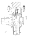
FIG. 1 is a cross-sectional view of an embodiment of an expansion valve; -
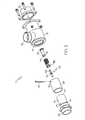
FIG. 2 is an exploded view of an embodiment of an expansion valve; and -
FIG. 3 is a cross-sectional view of an embodiment of an expansion valve in an opened position. - The detailed description explains embodiments of the invention, together with advantages and features, by way of example with reference to the drawings.
- Shown in
FIG. 1 is a cross sectional view of anexpansion valve 10. Theexpansion valve 10 includeshousing 12 having aninlet 14 and anoutlet 16. In the embodiment shown inFIG. 1 , an angle between theinlet 14 and theoutlet 16 is approximately 90 degrees. It is to be appreciated, however, that other angular configurations are contemplated by the present disclosure. - A
spool 18 is disposed at theinlet 14. Thespool 18 is substantially tubular in cross section and is open at anupstream end 20 and closed at adownstream end 22. Thespool 18 includes a plurality ofspool openings 24 extending through anouter surface 26 of thespool 18. In some embodiments, thespool openings 24 are substantially equally spaced around a circumference of thespool 18. Thespool openings 24 may be substantially any cross section, for example, circular, or as shown inFIG. 2 , slots. Thespool 18 is insertable into theinlet 14 and secured therein such that the plurality ofspool openings 24 are disposed inside of thehousing 12. Thespool 18 may be secured to thehousing 12 via, for example, a threadedconnection 26. - A
tubular sleeve 28 is disposed in thehousing 10. Thesleeve 28 extends over thespool 18 such that when thevalve 10 is in a closed position, as shown inFIG. 1 , thesleeve 28 covers each of thespool openings 24. Theouter surface 26 of the spool and aninner surface 30 of thesleeve 28 are configured to provide a desired degree of sealing at thespool openings 24 when thevalve 10 is in the closed position. Thesleeve 28 is connected to an activation mechanism, for example amotor 32, which articulates thesleeve 28 along aninlet axis 34 to uncover thespool openings 24 to open thevalve 10, as shown inFIG. 3 , and likewise cover thespool openings 24 to close thevalve 10. In some embodiments, themotor 32 is a stepper motor which is capable of moving thesleeve 28 in predetermined increments. - Referring to
FIG. 2 , thesleeve 28 is attached to themotor 32 via one or more connectingrods 36. In some embodiments, the connectingrod 36 includes a spring loadedseat 38 to absorb backlash in thevalve 10 and to maintain necessary clearances to ensure smooth operation of thevalve 10. Thesleeve 28 connects to the connectingrod 36 via apin 40 that extends throughsleeve holes 42 in thesleeve 28 and throughcorresponding rod holes 44 in the connectingrod 36. Further ananti-rotation yoke 46 may be disposed in an interior of the connectingrod 36. Theyoke 46 includestines 48 between which thepin 40 passes, and through corresponding rod holes (not shown) in the connectingrod 36. Theyoke 46 includeswrenching features 50 to allow theyoke 46 to be torqued into thespool 18. Theyoke 46 is fixed and retains the threaded connectingrod 36 from rotating to produce the axial translation of thesleeve 28 as an output shaft of themotor 32 rotates. - In operation, a
fluid flow 54 enters thevalve 10 at theinlet 14 and enters thesleeve 18 substantially parallel to theinlet axis 34. Thefluid flow 54 impacts the closeddownstream end 22 of thespool 18. As thefluid flow 54 impacts thedownstream end 22, thefluid flow 54 momentum forces are absorbed by thespool 18 which is grounded to thehousing 12. Reduction of momentum forces of thefluid flow 54 enables better control of thetubular sleeve 28. To allow thefluid flow 54 through thevalve 10 and out of theoutlet 16, themotor 32 is activated and thesleeve 28 is articulated along theinlet axis 34, as shown inFIG. 3 , to uncover the plurality ofspool openings 24. Thefluid flow 54 turns substantially perpendicular to theinlet axis 34 and flows through thespool openings 24 in a direction substantially parallel to anoutlet axis 56. As thefluid flow 54 passes through thespool openings 24, thefluid flow 54 impinges on an inner surface of thespool 28. Because thespool openings 24 are distributed around the circumference of thespool 28, the impingement forces are substantially in equal and opposite directions so that the resultant net force is substantially zero. In addition, both axial ends of thesleeve 18 are exposed to the same pressure environment, resulting in a pressure balancedsleeve 18. These features enable thetubular sleeve 18 to be exposed to reduced fluid flow and pressure variation effects, allowing for reduced forces to articulate thesleeve 18 through its required range of motion. By turning the flow from along theinlet axis 34 to along theoutlet axis 56, thedownstream end 22 of thespool 18 absorbs the impact forces of thefluid flow 54, rather than a valve stopper of the typical expansion valve. Further, since thesleeve openings 24 are equally spaced around thesleeve 28, side loads on the valve are reduced. In some embodiments, thedownstream end 22 of thespool 18 is concave, or as shown, v-shaped in cross-section to further absorb the impact forces of thefluid flow 54. - The configurations of the
valve 10 described having an axial inlet to thespool 18 and radial outlet from thespool 18 via the plurality ofspool openings 24 reduces the operating forces needed by themotor 32 to articulate thesleeve 28. Since themotor 32 does not have to overcome the fluid forces acting on the sleeve 28 (as it would in a conventional expansion valve) to close and/or open thevalve 10, the operating forces are reduced. - While the invention has been described in detail in connection with only a limited number of embodiments, it should be readily understood that the invention is not limited to such disclosed embodiments. Rather, the invention can be modified to incorporate any number of variations, alterations, substitutions or equivalent arrangements not heretofore described, but which are commensurate with the spirit and scope of the invention. Additionally, while various embodiments of the invention have been described, it is to be understood that aspects of the invention may include only some of the described embodiments. Accordingly, the invention is not to be seen as limited by the foregoing description, but is only limited by the scope of the appended claims.
Claims (15)
- A valve assembly (10) comprising:a housing (12) including an inlet (14) and an outlet (16);a tubular inlet spool (18) disposed in the inlet (14) having a closed downstream end (22) and a plurality of spool openings (24) through an outer surface (26) of the inlet spool (18); anda tubular sleeve (28) disposed over a circumference of the inlet spool (18) and articulable to substantially uncover the plurality of spool openings (24) thereby allowing a fluid flow (54) through the valve assembly (10).
- The valve assembly (10) of Claim 1 wherein the plurality of spool openings (24) are substantially equally spaced around the circumference of the inlet spool (18).
- The valve assembly (10) of Claim 1 or 2 wherein the outlet (16) is disposed such that the fluid flow (54) changes direction approximately ninety degrees between the inlet (14) and the outlet (16).
- The valve assembly (10) of any preceding Claim wherein the sleeve (28) is articulable substantially along an inlet central axis (34).
- The valve assembly (10) of any preceding Claim comprising a motor (32) operably connected to the sleeve (28) to articulate the sleeve (28).
- The valve assembly (10) of claim 5 wherein the sleeve (28) is connected to the motor (32) via at least one connecting rod (36).
- The valve assembly (10) of Claim 6 wherein the at least one connecting rod (36) is disposed in the housing (12).
- The valve assembly (10) of Claim 5, 6 or 7 wherein the motor (32) is a stepper motor.
- The valve assembly (10) of any preceding Claim wherein the valve assembly (10) is an expansion valve.
- A method of flowing a fluid (54) through a valve assembly (10) comprising:urging the fluid (54) into a tubular inlet spool (18) of the valve assembly (10) to a closed downstream end (22) of the inlet spool (18);directing the fluid (54) toward a plurality of spool openings (24) disposed in the outer surface (26) of the inlet spool (18);articulating a tubular sleeve (28) disposed over the circumference of the inlet spool (18) to substantially uncover the plurality of spool openings (24); andflowing the fluid (54) through the plurality of spool openings (24) toward an outlet (16) of the valve assembly (10).
- The method of Claim 10 comprising absorbing fluid impact forces in the closed downstream end (22) of the inlet spool (18).
- The method of Claim 10 or 11 wherein the fluid (54) is directed substantially radially outwardly toward the plurality of spool openings (24).
- The method of Claim 10, 11 or 12 wherein the plurality of spool openings (24) are substantially equally spaced around a circumference of the inlet spool (18).
- The method of Claim 10 wherein the sleeve (28) is articulated via a motor (32) in operable communication with the sleeve (28), and wherein, for example, operation of the motor (32) articulates a connecting rod (36) connected to the sleeve (28), motor (32) optionally being a stepper motor.
- The method of any of Claims 10 to 14 wherein the fluid flow (54) changes direction approximately ninety degrees between the inlet (14) and the outlet (16).
Applications Claiming Priority (1)
| Application Number | Priority Date | Filing Date | Title |
|---|---|---|---|
| US12/571,615 US20110079286A1 (en) | 2009-10-01 | 2009-10-01 | Expansion Valve |
Publications (3)
| Publication Number | Publication Date |
|---|---|
| EP2320166A2 true EP2320166A2 (en) | 2011-05-11 |
| EP2320166A3 EP2320166A3 (en) | 2014-04-02 |
| EP2320166B1 EP2320166B1 (en) | 2018-09-12 |
Family
ID=43413704
Family Applications (1)
| Application Number | Title | Priority Date | Filing Date |
|---|---|---|---|
| EP10251722.4A Not-in-force EP2320166B1 (en) | 2009-10-01 | 2010-10-01 | Expansion valve |
Country Status (3)
| Country | Link |
|---|---|
| US (1) | US20110079286A1 (en) |
| EP (1) | EP2320166B1 (en) |
| JP (1) | JP2011075272A (en) |
Families Citing this family (1)
| Publication number | Priority date | Publication date | Assignee | Title |
|---|---|---|---|---|
| US11719349B2 (en) * | 2021-11-16 | 2023-08-08 | Mueller Refrigeration, LLC | Axial three-way modulating valve |
Family Cites Families (30)
| Publication number | Priority date | Publication date | Assignee | Title |
|---|---|---|---|---|
| DE602948C (en) * | 1933-05-05 | 1934-09-20 | Esslingen Maschf | Control element for the refrigerant circulation |
| FR1186275A (en) * | 1957-12-30 | 1959-08-19 | Valve | |
| US3285285A (en) * | 1964-02-27 | 1966-11-15 | Koontz Wagner Electric Company | Valve |
| US3872685A (en) * | 1973-03-16 | 1975-03-25 | Controls Co Of America | Evaporator temperature control for refrigeration systems |
| FR2315051A1 (en) * | 1975-06-20 | 1977-01-14 | Bertin & Cie | SOUNDPROOF VALVE |
| FR2339203A1 (en) * | 1976-01-20 | 1977-08-19 | Bronzavia Sa | DEVICE FOR ADJUSTING THE DIFFERENTIAL PRESSURE BETWEEN TWO DIFFERENT PRESSURE POINTS OF A FLUID CIRCUIT |
| JPS5634216Y2 (en) * | 1977-05-12 | 1981-08-13 | ||
| JPS5597582A (en) * | 1979-01-19 | 1980-07-24 | Aisin Seiki Co Ltd | Proportional control electromagnetic valve |
| DE3009018C2 (en) * | 1980-03-08 | 1985-01-03 | Kienzle Apparate Gmbh, 7730 Villingen-Schwenningen | Multi-digit preset counter with automatic repetition of the preselected value |
| AU549713B2 (en) * | 1983-12-22 | 1986-02-06 | Carrier Corp. | Control of expansion valve in a refrigeration system |
| US4523436A (en) * | 1983-12-22 | 1985-06-18 | Carrier Corporation | Incrementally adjustable electronic expansion valve |
| US4754920A (en) * | 1986-11-28 | 1988-07-05 | Hamilton Standard Controls, Inc. | Compact operator for gas control valves |
| JPH0721370B2 (en) * | 1987-07-20 | 1995-03-08 | 株式会社豊田自動織機製作所 | Valve mechanism for superheat control of suction refrigerant |
| JPH02166367A (en) * | 1988-12-19 | 1990-06-27 | Fuji Koki Seisakusho:Kk | Temperature expansion valve |
| US5076326A (en) * | 1990-10-15 | 1991-12-31 | Coltec Industries Inc. | Electromagnetically operated fluid control valve |
| WO1994009329A1 (en) * | 1992-10-15 | 1994-04-28 | Parker Hannifin Corporation | Expansion valve for air conditioning system |
| EP0762442A1 (en) * | 1992-10-15 | 1997-03-12 | Parker Hannifin Corporation | Proportional solenoid |
| CN1046022C (en) * | 1994-09-26 | 1999-10-27 | 易通公司 | Right angle thermally responsive expansion valve |
| JPH09265322A (en) * | 1996-03-29 | 1997-10-07 | Osaka Gas Co Ltd | Valve structure for pressure governor |
| US5957161A (en) * | 1998-11-05 | 1999-09-28 | Borg-Warner Automotive, Inc. | Long stroke balanced solenoid |
| LU90467B1 (en) * | 1999-10-27 | 2001-04-30 | Luxembourg Patent Co | High pressure oxygen valve |
| JP3998887B2 (en) * | 2000-03-02 | 2007-10-31 | 株式会社不二工機 | Expansion valve |
| US6415595B1 (en) * | 2000-08-22 | 2002-07-09 | Hamilton Sundstrand Corporation | Integrated thermal management and coolant system for an aircraft |
| JP4485711B2 (en) * | 2001-06-12 | 2010-06-23 | 株式会社不二工機 | Expansion valve |
| US6588726B2 (en) * | 2001-07-13 | 2003-07-08 | Eaton Corporation | Load bearing solenoid operated valve and method of making same |
| JP3942848B2 (en) * | 2001-07-19 | 2007-07-11 | 株式会社テージーケー | Expansion valve unit |
| US6811135B2 (en) * | 2002-10-24 | 2004-11-02 | Eaton Corporation | Solenoid operated sleeve valve |
| US7024874B2 (en) * | 2003-09-22 | 2006-04-11 | Hamilton Sundstrand | Aircraft galley chiller system |
| ES1058644Y (en) * | 2004-10-08 | 2005-05-01 | Fagor S Coop | ELECTRONIC VALVE OF REGULATION OF A GAS FLOW FOR COOKING. |
| JP5022120B2 (en) * | 2007-07-03 | 2012-09-12 | 株式会社不二工機 | Motorized valves for air conditioning systems |
-
2009
- 2009-10-01 US US12/571,615 patent/US20110079286A1/en not_active Abandoned
-
2010
- 2010-09-24 JP JP2010213103A patent/JP2011075272A/en active Pending
- 2010-10-01 EP EP10251722.4A patent/EP2320166B1/en not_active Not-in-force
Non-Patent Citations (1)
| Title |
|---|
| None |
Also Published As
| Publication number | Publication date |
|---|---|
| EP2320166B1 (en) | 2018-09-12 |
| JP2011075272A (en) | 2011-04-14 |
| US20110079286A1 (en) | 2011-04-07 |
| EP2320166A3 (en) | 2014-04-02 |
Similar Documents
| Publication | Publication Date | Title |
|---|---|---|
| JP5232578B2 (en) | Pivot actuated sleeve valve | |
| US7434570B2 (en) | Snap-action valve for exhaust system | |
| JP6335900B2 (en) | Axial fluid valve with annular flow control member | |
| JP3307919B2 (en) | Valve device for fluid piping | |
| KR101915349B1 (en) | Steam valve and steam turbine | |
| US8336849B2 (en) | Conical seat shut off valve | |
| JP5781949B2 (en) | Pressure independent control valve | |
| RU2652361C1 (en) | Control valves | |
| EP2818666B1 (en) | Turbocharger with turbine nozzle vanes and an annular rotary bypass valve | |
| KR102006336B1 (en) | Rack and pinion type ball valve | |
| EP3749884B1 (en) | Axial flow slam-shut valve | |
| US20120255631A1 (en) | Check Valve | |
| SK91898A3 (en) | Controllable ball valve | |
| US20240003435A1 (en) | Ball valve | |
| KR20180070596A (en) | Bypass valve for turbocharger | |
| EP2320166B1 (en) | Expansion valve | |
| WO2008034879A1 (en) | Oil control valve | |
| US8251086B2 (en) | Rotary gate valve with secondary seal | |
| KR102056217B1 (en) | Optimum kinetic speed variable controller for nozzle check valve disc | |
| KR101149547B1 (en) | Check valve | |
| JP6946154B2 (en) | Valve gear and steam turbine | |
| CN102549323A (en) | Valve for a continuous-flow machine | |
| US12398810B2 (en) | Energy recovery valve system with spherical segment valve for controlling the fluid flow in a duct | |
| US20180371935A1 (en) | Valve system and steam turbine | |
| WO2001036850A1 (en) | Ball valve with non-return valve |
Legal Events
| Date | Code | Title | Description |
|---|---|---|---|
| PUAI | Public reference made under article 153(3) epc to a published international application that has entered the european phase |
Free format text: ORIGINAL CODE: 0009012 |
|
| AK | Designated contracting states |
Kind code of ref document: A2 Designated state(s): AL AT BE BG CH CY CZ DE DK EE ES FI FR GB GR HR HU IE IS IT LI LT LU LV MC MK MT NL NO PL PT RO RS SE SI SK SM TR |
|
| AX | Request for extension of the european patent |
Extension state: BA ME |
|
| PUAL | Search report despatched |
Free format text: ORIGINAL CODE: 0009013 |
|
| AK | Designated contracting states |
Kind code of ref document: A3 Designated state(s): AL AT BE BG CH CY CZ DE DK EE ES FI FR GB GR HR HU IE IS IT LI LT LU LV MC MK MT NL NO PL PT RO RS SE SI SK SM TR |
|
| AX | Request for extension of the european patent |
Extension state: BA ME |
|
| RIC1 | Information provided on ipc code assigned before grant |
Ipc: F25B 41/06 20060101AFI20140224BHEP |
|
| 17P | Request for examination filed |
Effective date: 20141002 |
|
| RBV | Designated contracting states (corrected) |
Designated state(s): AL AT BE BG CH CY CZ DE DK EE ES FI FR GB GR HR HU IE IS IT LI LT LU LV MC MK MT NL NO PL PT RO RS SE SI SK SM TR |
|
| STAA | Information on the status of an ep patent application or granted ep patent |
Free format text: STATUS: EXAMINATION IS IN PROGRESS |
|
| 17Q | First examination report despatched |
Effective date: 20170314 |
|
| GRAP | Despatch of communication of intention to grant a patent |
Free format text: ORIGINAL CODE: EPIDOSNIGR1 |
|
| STAA | Information on the status of an ep patent application or granted ep patent |
Free format text: STATUS: GRANT OF PATENT IS INTENDED |
|
| INTG | Intention to grant announced |
Effective date: 20180313 |
|
| GRAS | Grant fee paid |
Free format text: ORIGINAL CODE: EPIDOSNIGR3 |
|
| GRAA | (expected) grant |
Free format text: ORIGINAL CODE: 0009210 |
|
| STAA | Information on the status of an ep patent application or granted ep patent |
Free format text: STATUS: THE PATENT HAS BEEN GRANTED |
|
| AK | Designated contracting states |
Kind code of ref document: B1 Designated state(s): AL AT BE BG CH CY CZ DE DK EE ES FI FR GB GR HR HU IE IS IT LI LT LU LV MC MK MT NL NO PL PT RO RS SE SI SK SM TR |
|
| REG | Reference to a national code |
Ref country code: GB Ref legal event code: FG4D |
|
| REG | Reference to a national code |
Ref country code: CH Ref legal event code: EP |
|
| REG | Reference to a national code |
Ref country code: IE Ref legal event code: FG4D |
|
| REG | Reference to a national code |
Ref country code: DE Ref legal event code: R096 Ref document number: 602010053490 Country of ref document: DE |
|
| REG | Reference to a national code |
Ref country code: AT Ref legal event code: REF Ref document number: 1041071 Country of ref document: AT Kind code of ref document: T Effective date: 20181015 |
|
| REG | Reference to a national code |
Ref country code: FR Ref legal event code: PLFP Year of fee payment: 9 |
|
| REG | Reference to a national code |
Ref country code: NL Ref legal event code: MP Effective date: 20180912 |
|
| REG | Reference to a national code |
Ref country code: LT Ref legal event code: MG4D |
|
| PG25 | Lapsed in a contracting state [announced via postgrant information from national office to epo] |
Ref country code: BG Free format text: LAPSE BECAUSE OF FAILURE TO SUBMIT A TRANSLATION OF THE DESCRIPTION OR TO PAY THE FEE WITHIN THE PRESCRIBED TIME-LIMIT Effective date: 20181212 Ref country code: LT Free format text: LAPSE BECAUSE OF FAILURE TO SUBMIT A TRANSLATION OF THE DESCRIPTION OR TO PAY THE FEE WITHIN THE PRESCRIBED TIME-LIMIT Effective date: 20180912 Ref country code: RS Free format text: LAPSE BECAUSE OF FAILURE TO SUBMIT A TRANSLATION OF THE DESCRIPTION OR TO PAY THE FEE WITHIN THE PRESCRIBED TIME-LIMIT Effective date: 20180912 Ref country code: GR Free format text: LAPSE BECAUSE OF FAILURE TO SUBMIT A TRANSLATION OF THE DESCRIPTION OR TO PAY THE FEE WITHIN THE PRESCRIBED TIME-LIMIT Effective date: 20181213 Ref country code: NO Free format text: LAPSE BECAUSE OF FAILURE TO SUBMIT A TRANSLATION OF THE DESCRIPTION OR TO PAY THE FEE WITHIN THE PRESCRIBED TIME-LIMIT Effective date: 20181212 Ref country code: SE Free format text: LAPSE BECAUSE OF FAILURE TO SUBMIT A TRANSLATION OF THE DESCRIPTION OR TO PAY THE FEE WITHIN THE PRESCRIBED TIME-LIMIT Effective date: 20180912 Ref country code: FI Free format text: LAPSE BECAUSE OF FAILURE TO SUBMIT A TRANSLATION OF THE DESCRIPTION OR TO PAY THE FEE WITHIN THE PRESCRIBED TIME-LIMIT Effective date: 20180912 |
|
| PG25 | Lapsed in a contracting state [announced via postgrant information from national office to epo] |
Ref country code: ES Free format text: LAPSE BECAUSE OF FAILURE TO SUBMIT A TRANSLATION OF THE DESCRIPTION OR TO PAY THE FEE WITHIN THE PRESCRIBED TIME-LIMIT Effective date: 20180912 Ref country code: HR Free format text: LAPSE BECAUSE OF FAILURE TO SUBMIT A TRANSLATION OF THE DESCRIPTION OR TO PAY THE FEE WITHIN THE PRESCRIBED TIME-LIMIT Effective date: 20180912 Ref country code: AL Free format text: LAPSE BECAUSE OF FAILURE TO SUBMIT A TRANSLATION OF THE DESCRIPTION OR TO PAY THE FEE WITHIN THE PRESCRIBED TIME-LIMIT Effective date: 20180912 Ref country code: LV Free format text: LAPSE BECAUSE OF FAILURE TO SUBMIT A TRANSLATION OF THE DESCRIPTION OR TO PAY THE FEE WITHIN THE PRESCRIBED TIME-LIMIT Effective date: 20180912 |
|
| REG | Reference to a national code |
Ref country code: AT Ref legal event code: MK05 Ref document number: 1041071 Country of ref document: AT Kind code of ref document: T Effective date: 20180912 |
|
| PG25 | Lapsed in a contracting state [announced via postgrant information from national office to epo] |
Ref country code: NL Free format text: LAPSE BECAUSE OF FAILURE TO SUBMIT A TRANSLATION OF THE DESCRIPTION OR TO PAY THE FEE WITHIN THE PRESCRIBED TIME-LIMIT Effective date: 20180912 Ref country code: AT Free format text: LAPSE BECAUSE OF FAILURE TO SUBMIT A TRANSLATION OF THE DESCRIPTION OR TO PAY THE FEE WITHIN THE PRESCRIBED TIME-LIMIT Effective date: 20180912 Ref country code: IS Free format text: LAPSE BECAUSE OF FAILURE TO SUBMIT A TRANSLATION OF THE DESCRIPTION OR TO PAY THE FEE WITHIN THE PRESCRIBED TIME-LIMIT Effective date: 20190112 Ref country code: PL Free format text: LAPSE BECAUSE OF FAILURE TO SUBMIT A TRANSLATION OF THE DESCRIPTION OR TO PAY THE FEE WITHIN THE PRESCRIBED TIME-LIMIT Effective date: 20180912 Ref country code: EE Free format text: LAPSE BECAUSE OF FAILURE TO SUBMIT A TRANSLATION OF THE DESCRIPTION OR TO PAY THE FEE WITHIN THE PRESCRIBED TIME-LIMIT Effective date: 20180912 Ref country code: RO Free format text: LAPSE BECAUSE OF FAILURE TO SUBMIT A TRANSLATION OF THE DESCRIPTION OR TO PAY THE FEE WITHIN THE PRESCRIBED TIME-LIMIT Effective date: 20180912 Ref country code: CZ Free format text: LAPSE BECAUSE OF FAILURE TO SUBMIT A TRANSLATION OF THE DESCRIPTION OR TO PAY THE FEE WITHIN THE PRESCRIBED TIME-LIMIT Effective date: 20180912 Ref country code: IT Free format text: LAPSE BECAUSE OF FAILURE TO SUBMIT A TRANSLATION OF THE DESCRIPTION OR TO PAY THE FEE WITHIN THE PRESCRIBED TIME-LIMIT Effective date: 20180912 |
|
| PG25 | Lapsed in a contracting state [announced via postgrant information from national office to epo] |
Ref country code: PT Free format text: LAPSE BECAUSE OF FAILURE TO SUBMIT A TRANSLATION OF THE DESCRIPTION OR TO PAY THE FEE WITHIN THE PRESCRIBED TIME-LIMIT Effective date: 20190112 Ref country code: SM Free format text: LAPSE BECAUSE OF FAILURE TO SUBMIT A TRANSLATION OF THE DESCRIPTION OR TO PAY THE FEE WITHIN THE PRESCRIBED TIME-LIMIT Effective date: 20180912 Ref country code: SK Free format text: LAPSE BECAUSE OF FAILURE TO SUBMIT A TRANSLATION OF THE DESCRIPTION OR TO PAY THE FEE WITHIN THE PRESCRIBED TIME-LIMIT Effective date: 20180912 |
|
| REG | Reference to a national code |
Ref country code: CH Ref legal event code: PL |
|
| REG | Reference to a national code |
Ref country code: DE Ref legal event code: R097 Ref document number: 602010053490 Country of ref document: DE |
|
| REG | Reference to a national code |
Ref country code: BE Ref legal event code: MM Effective date: 20181031 |
|
| PG25 | Lapsed in a contracting state [announced via postgrant information from national office to epo] |
Ref country code: LU Free format text: LAPSE BECAUSE OF NON-PAYMENT OF DUE FEES Effective date: 20181001 |
|
| PLBE | No opposition filed within time limit |
Free format text: ORIGINAL CODE: 0009261 |
|
| STAA | Information on the status of an ep patent application or granted ep patent |
Free format text: STATUS: NO OPPOSITION FILED WITHIN TIME LIMIT |
|
| REG | Reference to a national code |
Ref country code: IE Ref legal event code: MM4A |
|
| PG25 | Lapsed in a contracting state [announced via postgrant information from national office to epo] |
Ref country code: DK Free format text: LAPSE BECAUSE OF FAILURE TO SUBMIT A TRANSLATION OF THE DESCRIPTION OR TO PAY THE FEE WITHIN THE PRESCRIBED TIME-LIMIT Effective date: 20180912 Ref country code: MC Free format text: LAPSE BECAUSE OF FAILURE TO SUBMIT A TRANSLATION OF THE DESCRIPTION OR TO PAY THE FEE WITHIN THE PRESCRIBED TIME-LIMIT Effective date: 20180912 |
|
| 26N | No opposition filed |
Effective date: 20190613 |
|
| GBPC | Gb: european patent ceased through non-payment of renewal fee |
Effective date: 20181212 |
|
| PG25 | Lapsed in a contracting state [announced via postgrant information from national office to epo] |
Ref country code: SI Free format text: LAPSE BECAUSE OF FAILURE TO SUBMIT A TRANSLATION OF THE DESCRIPTION OR TO PAY THE FEE WITHIN THE PRESCRIBED TIME-LIMIT Effective date: 20180912 Ref country code: LI Free format text: LAPSE BECAUSE OF NON-PAYMENT OF DUE FEES Effective date: 20181031 Ref country code: BE Free format text: LAPSE BECAUSE OF NON-PAYMENT OF DUE FEES Effective date: 20181031 Ref country code: CH Free format text: LAPSE BECAUSE OF NON-PAYMENT OF DUE FEES Effective date: 20181031 |
|
| PG25 | Lapsed in a contracting state [announced via postgrant information from national office to epo] |
Ref country code: IE Free format text: LAPSE BECAUSE OF NON-PAYMENT OF DUE FEES Effective date: 20181001 |
|
| PG25 | Lapsed in a contracting state [announced via postgrant information from national office to epo] |
Ref country code: GB Free format text: LAPSE BECAUSE OF NON-PAYMENT OF DUE FEES Effective date: 20181212 |
|
| PG25 | Lapsed in a contracting state [announced via postgrant information from national office to epo] |
Ref country code: MT Free format text: LAPSE BECAUSE OF NON-PAYMENT OF DUE FEES Effective date: 20181001 |
|
| PG25 | Lapsed in a contracting state [announced via postgrant information from national office to epo] |
Ref country code: TR Free format text: LAPSE BECAUSE OF FAILURE TO SUBMIT A TRANSLATION OF THE DESCRIPTION OR TO PAY THE FEE WITHIN THE PRESCRIBED TIME-LIMIT Effective date: 20180912 |
|
| PG25 | Lapsed in a contracting state [announced via postgrant information from national office to epo] |
Ref country code: CY Free format text: LAPSE BECAUSE OF FAILURE TO SUBMIT A TRANSLATION OF THE DESCRIPTION OR TO PAY THE FEE WITHIN THE PRESCRIBED TIME-LIMIT Effective date: 20180912 Ref country code: HU Free format text: LAPSE BECAUSE OF FAILURE TO SUBMIT A TRANSLATION OF THE DESCRIPTION OR TO PAY THE FEE WITHIN THE PRESCRIBED TIME-LIMIT; INVALID AB INITIO Effective date: 20101001 Ref country code: MK Free format text: LAPSE BECAUSE OF NON-PAYMENT OF DUE FEES Effective date: 20180912 |
|
| REG | Reference to a national code |
Ref country code: DE Ref legal event code: R079 Ref document number: 602010053490 Country of ref document: DE Free format text: PREVIOUS MAIN CLASS: F25B0041060000 Ipc: F25B0041300000 |
|
| PGFP | Annual fee paid to national office [announced via postgrant information from national office to epo] |
Ref country code: FR Payment date: 20210922 Year of fee payment: 12 |
|
| PGFP | Annual fee paid to national office [announced via postgrant information from national office to epo] |
Ref country code: DE Payment date: 20210921 Year of fee payment: 12 |
|
| REG | Reference to a national code |
Ref country code: DE Ref legal event code: R119 Ref document number: 602010053490 Country of ref document: DE |
|
| PG25 | Lapsed in a contracting state [announced via postgrant information from national office to epo] |
Ref country code: FR Free format text: LAPSE BECAUSE OF NON-PAYMENT OF DUE FEES Effective date: 20221031 Ref country code: DE Free format text: LAPSE BECAUSE OF NON-PAYMENT OF DUE FEES Effective date: 20230503 |