EP2320162A2 - Regenerative refrigerator - Google Patents
Regenerative refrigerator Download PDFInfo
- Publication number
- EP2320162A2 EP2320162A2 EP10009563A EP10009563A EP2320162A2 EP 2320162 A2 EP2320162 A2 EP 2320162A2 EP 10009563 A EP10009563 A EP 10009563A EP 10009563 A EP10009563 A EP 10009563A EP 2320162 A2 EP2320162 A2 EP 2320162A2
- Authority
- EP
- European Patent Office
- Prior art keywords
- flat surface
- working fluid
- metal
- refrigerator
- cylinder
- Prior art date
- Legal status (The legal status is an assumption and is not a legal conclusion. Google has not performed a legal analysis and makes no representation as to the accuracy of the status listed.)
- Granted
Links
Images






Classifications
-
- F—MECHANICAL ENGINEERING; LIGHTING; HEATING; WEAPONS; BLASTING
- F25—REFRIGERATION OR COOLING; COMBINED HEATING AND REFRIGERATION SYSTEMS; HEAT PUMP SYSTEMS; MANUFACTURE OR STORAGE OF ICE; LIQUEFACTION SOLIDIFICATION OF GASES
- F25B—REFRIGERATION MACHINES, PLANTS OR SYSTEMS; COMBINED HEATING AND REFRIGERATION SYSTEMS; HEAT PUMP SYSTEMS
- F25B9/00—Compression machines, plants or systems, in which the refrigerant is air or other gas of low boiling point
- F25B9/14—Compression machines, plants or systems, in which the refrigerant is air or other gas of low boiling point characterised by the cycle used, e.g. Stirling cycle
Definitions
- the present invention relates generally to refrigerators, and more particularly to a regenerative refrigerator capable of switching the feeding of working fluid to a cylinder and the discharging of the working fluid from the cylinder using a rotary valve.
- the "regenerative refrigerator” may mean refrigerators in general that generates coldness (cold temperatures) such as cryogenic temperatures in a cylinder containing a regenerator material through an adiabatic expansion of working fluid flowing into the cylinder, such as a Gifford-McMahon (GM) refrigerator, a pulse tube refrigerator, and a Solvay refrigerator.
- cold temperatures such as cryogenic temperatures in a cylinder containing a regenerator material through an adiabatic expansion of working fluid flowing into the cylinder
- GM Gifford-McMahon
- GM Gifford-McMahon refrigerator
- pulse tube refrigerator a pulse tube refrigerator
- Gifford-McMahon (GM) refrigerator has been known as a refrigerator capable of generating cryogenic temperatures.
- GM refrigerator attains a cooling effect based on Gifford-McMahon refrigeration cycle using a change in the volume of a space caused by the reciprocation of a displacer inside a cylinder.
- high-pressure working fluid such as helium gas
- a regenerator material provided in the cylinder to be raised to room temperature, and is thereafter discharged from the cylinder.
- cryogenic temperatures are maintained inside the cylinder, so that an object of cooling thermally coupled to the cylinder is cooled.
- the working fluid discharged from the cylinder is compressed in a compressor into high-pressure working fluid. Thereafter, this high-pressure working fluid is re-fed to the cylinder.
- GM refrigerator includes a switching valve such as a rotary valve in order to perform such feeding and discharging of working fluid to and from the cylinder.
- a switching valve such as a rotary valve in order to perform such feeding and discharging of working fluid to and from the cylinder.
- the rotary valve includes a valve plate, which is a cylindrical rotator, and a valve body, which is static.
- a valve plate which is a cylindrical rotator
- a valve body which is static.
- a combination of metal and resin has been used as a combination of the materials of the sliding surfaces of the valve plate and the valve body of the rotary valve.
- Aluminum or its alloy is used as the metal.
- the sliding surface is subjected in advance to surface modification by anodizing, and is thereafter subjected to polish finishing.
- a technique has been proposed to coat the sliding surface with a thin film of diamond-like carbon (DLC).
- a regenerative refrigerator includes a compressor configured to compress a working fluid; a cylinder configured to be fed with the compressed working fluid, the cylinder containing a regenerator material and having an expansion space provided at one end thereof; and a rotary valve provided between the compressor and the cylinder, the rotary valve being configured to switch a first passage and a second passage, the first passage being formed to cause the working fluid to flow from the compressor to the expansion space, the second passage being formed to cause the working fluid to flow from the expansion space to the compressor, wherein the working fluid expands in the expansion space to generate cold temperatures in the cylinder, the rotary valve includes a valve body having a first flat surface; and a valve plate having a second flat surface, the valve plate being configured to rotate with the first flat surface and the second flat surface in surface contact, and a first one of the first flat surface and the second flat surface has an arithmetic average roughness of 0.1 ⁇ m to 0.9 ⁇ m, and a second one of the first flat surface and the second flat surface
- a combination of metal and resin can be used as a combination of the materials of the sliding surfaces of the valve plate and the valve body of the rotary valve, and aluminum or its alloy can be used as the metal.
- the combination of an aluminum alloy (anodized) and resin as described above has a problem in that it is desired to perform maintenance or change parts at relatively short intervals because the sliding surfaces are likely to be worn by abrasion.
- a regenerative refrigerator includes a rotary valve stably usable for a long period of time with the wear of its sliding part due to abrasion being significantly reduced.
- a method of manufacturing the rotary valve of the regenerative refrigerator is provided.
- a method of manufacturing the regenerative refrigerator is provided.
- FIG. 1 is a schematic cross-sectional view of a Gifford-McMahon (GM) refrigerator according to the embodiment of the present invention.
- GM Gifford-McMahon
- a GM refrigerator 100 includes a gas compressor 101 and a cold head 102.
- the cold head 102 includes a housing part 123 and a cylinder part 110.
- the gas compressor 101 draws in working fluid through an intake port 101a, compresses the working fluid, and discharges the high-pressure working fluid through a discharge port 101b.
- Helium gas is usually used as the working fluid.
- the cylinder part 110 has a two-stage structure of a first-stage cylinder 110a and a second-stage cylinder 110b.
- the second-stage cylinder 110b is smaller in diameter than the first-stage cylinder 110a.
- Displacers 103a and 103b are inserted in the cylinders 110a and 110b, respectively, so as to be reciprocatable in the cylinders 110a and 110b in their axial directions.
- the displacers 103a and 103b are interconnected. Further, the displacers 103a and 103b have their respective gas passages formed inside, which gas passages are filled with regenerator materials 104 and 105, respectively.
- a first-stage expansion chamber 111 is formed at one end of the first-stage cylinder 110a on the second-stage cylinder 110b side. Further, an upper chamber 113 is formed at the other end of the first-stage cylinder 110a.
- a second-stage expansion chamber 112 is formed at an end of the second-stage cylinder 110b on the side opposite from the first-stage cylinder 110a side.
- the upper chamber 113 communicates with the first-stage expansion chamber 111 via a gas passage L1 provided at the upper end of the displacer 103a, the gas passage filled with the regenerator material 104 inside the displacer 103a, and a gas passage L2 provided at the lower end of the displacer 103a.
- the first-stage expansion chamber 111 communicates with the second-stage expansion chamber 112 via a gas passage L3 provided at the upper end of the displacer 103b, the gas passage filled with the regenerator material 105 inside the displacer 103b, and a gas passage L4 provided at the lower end of the displacer 103b.
- a first-stage cooling stage 106 formed of a thermally conductive material is attached to the exterior cylindrical surface (peripheral surface) of the first-stage cylinder 110a at a position corresponding to the first-stage expansion chamber 111. Further, a second-stage cooling stage 107 formed of a thermally conductive material is attached to the exterior cylindrical surface (peripheral surface) of the second-stage cylinder 110b at a position corresponding to the second-stage expansion chamber 112.
- a sealing mechanism 150 is provided on the exterior cylindrical surface (peripheral surface) of the first-stage displacer 103a near its end on the upper chamber 113 side.
- the sealing mechanism 150 seals the clearance between the exterior cylindrical surface of the displacer 103a and the interior cylindrical surface of the first-stage cylinder 110a.
- a Scotch yoke 122 is connected to the first-stage displacer 103a.
- the Scotch yoke 122 extends outward (upward in FIG. 1 ) from the first-stage cylinder 110a.
- the Scotch yoke 122 is supported by sleeve bearings 117a and 117b fixed to a housing 124 so as to be movable in the axial directions of the displacers 103a and 103b.
- the airtightness of a sliding part is maintained at the sleeve bearing 117b, so that the space inside the housing 124 and the upper chamber 113 are separated.
- a motor 115 is housed in the housing 124. The rotation of the motor 115 is transmitted to the displacer 103a via a crank 114 and the Scotch yoke 122. Thereby, the displacers 103a and 103b are reciprocated.
- a rotary valve 155 is provided between the intake port 101a and the discharge port 101b of the gas compressor 101 and the upper chamber 113.
- the rotary valve 155 switches the working fluid channel (from one to another) so as to introduce the working fluid discharged from the discharge port 101b of the gas compressor 101 into the upper chamber 113 or introduce the working fluid inside the upper chamber 113 to the intake port 101a of the gas compressor 101.
- the rotary valve 155 includes a valve body 161 and a valve plate 171.
- the valve plate 171 is rotatably supported by a rolling bearing 116 in the housing 124.
- An eccentric pin 114a of the crank 114 which drives the Scotch yoke 122, revolves around an axis of rotation, so that the valve plate 171 rotates.
- the valve body 161 is pressed against the valve plate 171 by a coil spring 120. However, the valve body 161 is locked by a pin 119 so as not to rotate.
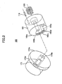
- FIG. 2 is an exploded perspective view of the rotary valve 155.
- the cylindrical valve body 161 includes a flat surface 165a. Further, a gas passage 165b is formed in the cylindrical valve body 161. The gas passage 165b penetrates through the valve body 161 along the center axis of the valve body 161. One end of the gas passage 165b is open at the flat surface 165a. The other end of the gas passage 165b is connected to the discharge port 101b of the gas compressor 101 illustrated in FIG. 1 .
- a groove 165c is formed along an arc (of a circle) having a center at the center axis of the valve body 161 at the flat surface 165a of the valve body 161.
- An end part 165d of the groove 165c is connected to one end of an L-shaped gas passage 165e formed inside the valve body 161.
- the other end of the gas passage 165e has an opening at the exterior cylindrical surface (peripheral surface) of the valve body 161.
- the gas passage 165e communicates with the upper chamber 113 via this opening and a gas passage 121 illustrated in FIG. 1 .
- the valve plate 171 has a flat surface 175a that is in surface contact with the flat surface 165a of the valve body 161.
- a groove 175d is formed at the flat surface 175a.
- the groove 175d extends along a radial direction of the flat surface 175a from the center of the flat surface 175a. Accordingly, when the valve plate 171 rotates so that the peripheral-side end part of the groove 175d overlaps (in part) with the groove 165c of the flat surface 165a of the valve body 161, the gas passage 165b and the gas passage 165e communicate with each other via the groove 175d.
- a gas passage 175b is formed in the valve plate 171 to extend from the flat surface 175a along the directions of the axis of rotation of the valve plate 171 so as to penetrate through the valve plate 171 in its axial directions.
- One end of the gas passage 175b is open at the flat surface 175a.
- the gas passage 175b is open in the flat surface 175a at substantially the same radial position as the groove 165c is open in the flat surface 165a of the valve body 161.
- the other end of the gas passage 175b is connected to the intake port 101a of the gas compressor 101 via a hollow inside the housing 124 as illustrated in FIG. 1 .
- the valve plate 171 rotates so that the opening of the gas passage 175b at the flat surface 175a overlaps (in part) with the groove 165c of the valve body 161, the gas passage 165e and the gas passage 175b communicate with each other.
- the upper chamber 113 communicates with the intake port 101a of the gas compressor 101 via the gas passage 121, the gas passage 165e, and the gas passage 175b.
- the working fluid is fed into the upper chamber 113 from the gas compressor 101 when the gas passage 165b and the gas passage 165e communicate with each other via the groove 175d.
- the working fluid inside the upper chamber 113 is collected into the gas compressor 101. Accordingly, by rotating the valve plate 171, it is possible to repeatedly introduce working fluid into the upper chamber 113 and collect the working fluid from the upper chamber 113.
- the volume of the upper chamber 113 is reduced, while the volumes of the first-stage expansion chamber 111 and the second-stage expansion chamber 112 increase.
- the displacers 103a and 103b move to the opposite side, the increase and the decrease in volume are reversed.
- the volumes of the first-stage expansion chamber 111 and the second-stage expansion chamber 112 increase, the working fluid expands adiabatically to generate cold temperatures inside the first-stage expansion chamber 111 and the second-stage expansion chamber 112.
- the working fluid moves through the gas passages L1 through L4 with changes in the volumes of the upper chamber 113, the first-stage expansion chamber 111, and the second-stage expansion chamber 112. During this, heat exchange is performed between the low-temperature working fluid and the regenerator materials 104 and 105.
- the repetition of the introduction and collection of working fluid and the reciprocation of the displacers 103a and 103b as described above synchronize with the rotation of the crank 114. Accordingly, by suitably adjusting the phase of the repetition of the introduction and collection of working fluid and the phase of the reciprocation of the displacers 103a and 103b, it is possible to continuously generate cold temperatures inside the first-stage expansion chamber 111 and the second-stage expansion chamber 112. Further, this makes it possible to cool an object of cooling (not graphically illustrated) attached to the first-stage cooling stage 106 and the second-stage cooling stage 107.
- a combination of resin and non-magnetic metal can be used as a material combination for the flat surface 165a of the valve body 161 and the flat surface 175a of the valve plate 171 of the rotary valve 155.
- Non-magnetic metal can be used because use of magnetic metal may cause the rotary valve 155 to adversely affect the operations of the GM refrigerator 100 and an object of cooling connected to the GM refrigerator 100.
- the object of cooling is often a device or an apparatus using magnetic properties, such as a superconducting device.
- Aluminum or its alloy is employed as non-magnetic material, and tetrafluoroethylene (for example, BEAREE FL 3000, manufactured by NTN Corporation) is employed as resin.
- tetrafluoroethylene for example, BEAREE FL 3000, manufactured by NTN Corporation
- aluminum and its alloys are relatively low in hardness. Therefore, when aluminum or its alloy is used for a sliding surface of a rotary valve (the flat surface 165a or 175a in this case), this sliding surface is subjected in advance to surface modification by anodizing. The anodized sliding surface is thereafter subjected to polish finishing, so that a smooth flat surface is finally obtained.
- the arithmetic average roughness Ra of the sliding surface finally obtained by this method is less than 0.1 ⁇ m.
- the degree of abrasion of the coated flat surface is somewhat reduced.
- the other flat surface for example, the flat surface 165a in FIG. 2
- this flat surface for example, the flat surface 175a in FIG. 2
- this technique is not a fundamental solution to the problem.
- the arithmetic average roughness Ra of one flat surface (for example, the flat surface 175a of the valve plate 171) may be in the range of 0.1 ⁇ m to 0.9 ⁇ m, and a metal-doped carbon film may be provided at this flat surface.
- the surface roughness Ra of a metal-side flat surface is controlled to less than 0.10 ⁇ m.
- the surface roughness Ra of the flat surface 175a of the valve plate 171 is more than or equal to 0.1 ⁇ m. This is based on the experimental result, which has been obtained for the first time by the inventors of the present invention, that the abrasion loss of the flat surface 165a of the counterpart valve body 161 increases as the surface roughness Ra of the flat surface 175a of the valve plate 171 decreases where the surface roughness Ra of the flat surface 175a is less than 0.1 ⁇ m.
- FIG. 3 is a graph illustrating the relationship between the surface roughness Ra of the flat surface 175a of the valve plate 171 and the abrasion loss of the flat surface 165a of the valve body 161, measured by the inventors of the present invention.
- the flat surface 175a used in this experiment (measurement) is formed of an aluminum alloy subjected to polish finishing after anodizing.
- the flat surface 165a is formed of three kinds of material, which are polyether sulfone (PES), wholly aromatic polyester (WAPE), and polytetrafluoroethylene (PTFE).
- PES polyether sulfone
- WAPE wholly aromatic polyester
- PTFE polytetrafluoroethylene
- This graph shows that in the range where the surface roughness Ra is less than 0.1 ⁇ m, the abrasion loss of the flat surface 165a of the valve body 161 increases as the surface roughness Ra decreases.
- One reason for this behavior is believed to be that if the flat surface 175a is excessively smooth, adhesion is likely to occur between the flat sliding surfaces 165a and 175a, thus resulting in poor slidability (increased friction) between them. Further, another possible reason is that excessive smoothness of the flat surface 175a causes its edge-like (sharply pointed) projecting portions to be relatively emphasized so that these projecting portions are likely to cause sharp "scratch damage" to the opposed flat surface 165a.
- the abrasion loss of the flat surface 165a of the valve body 161 hardly changes even with an increase in the surface roughness Ra of the flat surface 175a where the surface roughness Ra of the flat surface 175a is more than or equal to 0.1 ⁇ m. This is believed to be because there is more slidability between the flat surfaces 165a and 175a (that is, the flat surfaces 165a and 175a slide relative to each other more smoothly) in the case of a surface roughness Ra of more than or equal to 0.1 ⁇ m than in the case of a surface roughness Ra of less than 0.1 ⁇ m.
- edge-like projecting portions are relatively inconspicuous on the flat surface 175a to make it less likely to cause sharp "scratch damage" to the opposed flat surface 165a so that there is not much increase in the abrasion loss of the flat surface 165a.
- the surface roughness Ra of the flat surface 175a of the valve plate 171 being more than or equal to 0.1 ⁇ m, it is possible to reduce the abrasion loss of the flat surface 165a of the valve body 161 compared with the conventional case.
- the upper limit of the surface roughness Ra of the flat surface 175a of the valve plate 171 is 0.9 ⁇ m. This is because the abrasion loss of the flat surface 165a of the valve body 161 starts to increase again if the surface roughness Ra of the flat surface 175a of the valve plate 171 exceeds 0.9 ⁇ m, as is clear from FIG. 3 .
- One reason for this behavior is believed to be that if the surface roughness Ra of the flat surface 175a increases to exceed 0.9 ⁇ m, the damage to the flat surface 165a caused by projecting portions of the flat surface 175a becomes more conspicuous as has been expected.
- the surface roughness Ra of the flat surface 175a on the metal side is adjusted to the range of 0.1 ⁇ m to 0.9 ⁇ m according to this embodiment.
- a surface having such a surface roughness range may be obtained easily by application of, for example, shot peening with ceramic particles in the range of 10 ⁇ m to 200 ⁇ m in particle size.
- the "metal-doped carbon film” means a film in general that has a metal dispersed or disposed in a carbon film employed as a matrix.
- the metal may be dispersed as particles or disposed in layers in the carbon matrix.
- the metal-doped carbon film serves to improve the abrasion resistance of a surface on which the metal-doped carbon film is provided. Accordingly, by providing a metal-doped carbon film at the flat surface 175a of the valve plate 171, the abrasion of the flat surface 175a is prevented.
- the inventors of the present invention have found that there is little change in the surface roughness Ra before and after the provision of the metal-doped carbon film unless the metal-doped carbon film is extremely thick.
- FIG. 4 is a diagram for illustrating this maintenance of the surface roughness Ra before and after the provision of the metal-doped carbon film.
- (a) illustrates the valve plate 171 before provision of a metal-doped carbon film 172 on a flat surface 175a'
- (b) illustrates the valve plate 171 having the metal-doped carbon film 172 formed on the flat surface 175a' of (a) of FIG. 4 .
- the surface roughness Ra of the flat surface 175a' is controlled to 0.1 ⁇ m to 0.9 ⁇ m before the provision of the metal-doped carbon film 172, this surface roughness Ra is maintained in the flat surface 175a after the provision of the metal-doped carbon film 172.
- Examples of the metal material contained in the metal-doped carbon film of this embodiment which may be the metal-doped carbon film illustrated in (b) of FIG. 4 , include chromium (Cr), titanium (Ti), tungsten (W), silicon (Si), molybdenum (Mo), and combinations of two or more of these materials.
- the carbon film (matrix portion) may be DLC.
- the thickness of the metal-doped carbon film 172 is not limited in particular, and may be, for example, in the range of 1 ⁇ m to 15 ⁇ m. If the thickness of the metal-doped carbon film 172 is extremely large, the surface roughness Ra of the flat surface 175a illustrated in (b) of FIG. 4 (that is, the ultimately-obtained surface roughness Ra) may be out of the range of 0.1 ⁇ m to 0.9 ⁇ m even if the surface roughness Ra of the flat surface 175a' illustrated in (a) of FIG. 4 is controlled in advance to the 0.1 ⁇ m to 0.9 ⁇ m range before the provision of the metal-doped carbon film 172. In this case, after the provision of the metal-doped carbon film 172, the flat surface 175a is finished so as to have a surface roughness Ra in the range of 0.1 ⁇ m to 0.9 ⁇ m.
- the metal-doped carbon film 172 may be provided directly on the base material (such as an aluminum alloy or an anodized surface) forming the flat surface 175a' of the valve plate 171 as illustrated in FIG. 4 .
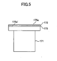
- the metal-doped carbon film 172 may be provided on an intermediate layer 173 provided on the base material (the flat surface 175a') as illustrated in FIG. 5 .
- the interposition of the intermediate layer 173 between the base material and the metal-doped carbon film 172 increases the adhesion of the metal-doped carbon film 172.
- the intermediate layer 173 include a nickel (Ni) plating layer and a chromium (Cr) plating layer.
- a chromium nitride (CrN) layer may be provided on the surface of the base material (the flat surface 175a') by a technique such as chemical vapor deposition (CVD), and be employed as the intermediate layer 173.
- the thickness of the intermediate layer 173 may be, for example, in the range of 1 ⁇ m to 15 ⁇ m.
- the resin forming the flat surface 165a of the valve body 161, which is in surface contact with the flat surface 175a of the valve plate 171 having the metal-doped carbon film 172 provided at the flat surface 175a, is preferably formed of engineering plastics.
- the resin may include at least one material selected from the group consisting of polyimide, polyether ether ketone, polyamide-imide, polyether ether sulfone, and phenolic resin.
- the resin may also be a mixture of polyamide-imide and polytetrafluoroethylene (PTFE).
- the resin may contain polyether sulfone (PES), wholly aromatic polyester (WAPE), and/or polytetrafluoroethylene (PTFE).
- the flat surface 165a in the case of using a resin including PES, WAPE, and PTFE (hereinafter referred to as "three-kind-mixture resin") for the flat surface 165a, a coefficient of friction is significantly reduced between the flat surface 165a and the flat surface 175a including the metal-doped carbon film 172. Accordingly, the "three-kind-mixture resin" is particularly preferable.
- the rotary valve 155 of this embodiment may also be applied to other apparatuses having the same cooling mechanism as the GM refrigerator, such as a single-stage or multi-stage pulse tube refrigerator and a Solvay refrigerator.
- the inventors of the present invention have further advanced research and development to find that the abrasion loss of the flat surfaces of the valve plate and the valve body of a rotary valve may be significantly reduced without providing a metal-doped carbon film on the metal-side flat surface, that is, the abrasion loss may be significantly reduced compared with the conventional case only by causing the arithmetic average roughness Ra of the metal-side flat surface to be controlled to the above-described range.
- a regenerative refrigerator including: a compressor configured to compress a working fluid; a cylinder configured to be fed with the compressed working fluid, the cylinder containing a regenerator material and having an expansion space provided at one end thereof; and a rotary valve provided between the compressor and the cylinder, the rotary valve being configured to switch a first passage and a second passage, the first passage being formed to cause the working fluid to flow from the compressor to the expansion space, the second passage being formed to cause the working fluid to flow from the expansion space to the compressor, wherein the working fluid expands in the expansion space to generate cold temperatures in the cylinder, the rotary valve includes a valve body having a first flat surface; and a valve plate having a second flat surface, the valve plate being configured to rotate with the first flat surface and the second flat surface in surface contact, and a first one of the first flat surface and the second flat surface has an arithmetic average roughness of 0.1 ⁇ m to 0.9 ⁇ m, and a second one of
- the first one of the first flat surface and the second flat surface may be, for example, the flat surface 175a' illustrated in (a) of FIG. 4 , and the flat surface 175a illustrated in FIG. 2 may be replaced with the flat surface 175a'.
- the flat surface 175a' may include one of an aluminum metal and an aluminum alloy as a base material.
- the surface (the flat surface 175a') of the aluminum metal or the aluminum alloy be anodized.
- the thickness of the anodized layer may be, for example, approximately 5 ⁇ m to approximately 100 ⁇ m (for example, 20 ⁇ m, 50 ⁇ m, etc.).
- the flat metal surface having an arithmetic average roughness Ra in such a range may be formed easily with shot peening as described above. For example, by performing shot peening on an anodized aluminum metal or aluminum alloy, using ceramic particles of approximately 1 ⁇ m to approximately 200 ⁇ m in average particle size as a medium, it is possible to form a surface having an arithmetic average roughness Ra in the range of 0.1 ⁇ m to 0.9 ⁇ m with ease.
- Examples of the material of the ceramic particles as a medium include alumina, silica (including sand or glass containing silica as a principal component), and zirconia.
- the arithmetic average roughness Ra in each example was calculated (determined) as follows. First, five samples manufactured by the same method were prepared. At or near the center of one of the samples, the surface roughness was measured once in each of a direction substantially parallel to the direction of surface polishing (or an arbitrarily determined first direction if the direction of surface polishing is unknown) and a direction substantially perpendicular to the direction of surface polishing (or a second direction substantially perpendicular to the first direction if the direction of surface polishing is unknown), and the average of the measurements was determined (referred to as "Value 1"). The same measurement was performed at two points in the peripheral portion of the disk (sample), and an average was determined in each measurement so that Value 2 and Value 3 were obtained.
- Aluminum alloy disks (50 mm in diameter and 7 mm in thickness) were prepared, and were anodized by a common method. By anodizing, the hardness of the aluminum alloy disks increased from pre-anodizing 150 Hv to approximately 500 Hv. Next, these treated (anodized) surfaces were subjected to mechanical polishing. The arithmetic average roughness Ra of the surfaces was measured to be approximately 0.08 ⁇ m.
- FIG. 6 illustrates electron microscope photographs of a polished surface.
- (a) is a photograph of low magnification (200-fold magnification)
- (b) is a photograph of high magnification (3000-fold magnification).
- FIG. 6 shows that while the processed surface is relatively smooth, sharply-pointed "edge-like" projecting portions are formed linearly along the same direction partly on the surface.
- Example 2 The same as in Example 1, aluminum alloy disks (50 mm in diameter and 7 mm in thickness) were anodized, and thereafter, their surfaces were further subjected to shot peening using alumina particles of 30 ⁇ m to 50 ⁇ m in particle size.
- the arithmetic average roughness Ra of the processed surfaces was measured to be approximately 0.79 ⁇ m (a value determined by the above-described method).
- FIG. 7 illustrates electron microscope photographs of an obtained surface.
- (a) is a photograph of low magnification (200-fold magnification)
- (b) is a photograph of high magnification (3000-fold magnification).
- FIG. 7 shows that the processed surface is uneven with numerous relatively-large projecting and depressed portions. However, such sharply-pointed "edge-like" projecting portions as in FIG. 6 were not observed, and it is shown that projecting portions have a relatively round form.
- a Ni plating film was provided on the surfaces of the aluminum alloy disks subjected to shot peening by electroless plating.
- the Ni plating film was approximately 10 ⁇ m in thickness.
- a carbon film containing tungsten was further provided on the surfaces.
- a common physical vapor deposition (PVD) technique was employed to deposit the carbon film containing tungsten.
- the film was formed by sputtering, causing argon ions to collide with two targets of carbon and tungsten.
- the carbon film containing tungsten was approximately 2 ⁇ m in thickness.
- FIG. 8 illustrates electron microscope photographs of an obtained surface after the provision of the carbon film containing tungsten.
- (a) is a photograph of low magnification (200-fold magnification)
- (b) is a photograph of high magnification (3000-fold magnification).
- FIG. 8 shows that while the surface still includes large unevenness, "edge-like" projecting portions as in Example 1 are not formed on the surface. It has been found from the comparison of the photographs of FIG. 7 and FIG. 8 that projecting portions of the surface tend to be further rounded with the provision of the carbon film containing tungsten.
- the arithmetic average roughness Ra of the surfaces was measured to be approximately 0.8 ⁇ m (the average of five measurements), which is substantially the same as the value after shot peening.
- An abrasion test (ring-on-disk test) was conducted using the aluminum alloy disks of Examples 1 and 2 and a resin ring.
- the resin ring was 37 mm in diameter and 6 mm in thickness.
- the rotating resin ring was pressed against a stationary aluminum alloy disk, and a change over time in the coefficient of friction at their contact surface was monitored.
- the pressing pressure was 0.25 MPa, and the rotational speed of the resin ring was 180 rpm.
- No lubricant was used in order to simulate an actual environment.
- the test was conducted in a helium gas atmosphere. The test time was 168 hours. After the measurement, the abrasion loss of the aluminum alloy disk and the resin ring was measured.
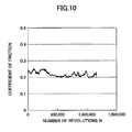
- FIG. 9 and FIG. 10 illustrate the measurement results of the change over time in the coefficient of friction in Example 1 and Example 2, respectively.
- FIG. 9 shows that the friction of coefficient at the interface between the aluminum alloy disk and the resin ring varies greatly between 0.18 and 0.30 in the case of using the aluminum alloy disks of Example 1.
- Such a variation in the coefficient of friction is not preferable for the rotary valve. This is because the occurrence of such a variation in the coefficient of friction between the flat surfaces of the valve plate and the valve body of the rotary valve may cause a variation in the load of a motor that rotates the valve plate of the rotary valve, thus shortening the useful service life of the motor. Further, a variation in the load of the motor may be a factor of impairment of the operational stability of the refrigerator as a whole, such as a cooling characteristic.
- FIG. 10 shows that in the case of using the aluminum alloy disks of Example 2, a variation over time is relatively small with the coefficient of friction at the interface being controlled to 0.20 to 0.25.
- Table 1 below shows the results of measurement of the abrasion loss generated in the case of using the aluminum alloy disks of Example 1 and Example 2.
- Table 1 Example Abrasion Loss (mg) Variation Range of Coefficient of Friction Metal Disk Side Resin Ring Side Example 1 0.2 46.4 0.18-0.30 Example 2 0.2 30.1 0.20-0.25
- Example 1 the abrasion loss of the aluminum alloy disk is 0.2 mg, while the abrasion loss of the resin ring is high at 46.4 mg.
- Example 2 the abrasion loss of the aluminum alloy disk is 0.2 mg, which is the same as in Example 1, while the abrasion loss of the resin ring is 30.1 mg, which is reduced by approximately 35% compared with Example 1.
- the abrasion of a metal flat surface is controlled and the abrasion of a resin flat surface in surface contact with the metal flat surface also is significantly reduced.
- Example 2 The same as in Example 1, aluminum alloy disks (50 mm in diameter and 7 mm in thickness) were anodized, and thereafter, their surfaces were further subjected to shot peening using alumina particles of 30 ⁇ m to 50 ⁇ m in particle size.
- the arithmetic average roughness Ra of the processed surfaces was measured to be approximately 0.2 ⁇ m (a value determined by the above-described method).
- FIG. 11 illustrates electron microscope photographs of an obtained surface.
- (a) is a photograph of low magnification (200-fold magnification)
- (b) is a photograph of high magnification (3000-fold magnification).
- the above-described abrasion test (ring-on-disk test) was conducted using the aluminum alloy disks of Examples 1 and 3 and a resin ring.
- the resin ring was 37 mm in diameter and 9 mm in thickness.
- the rotating resin ring was pressed against a stationary aluminum alloy disk, and the abrasion of the aluminum alloy disk and the resin ring was measured after passage of a predetermined period of time.
- the pressing pressure was 0.25 MPa, and the rotational speed of the resin ring was 135 rpm.
- No lubricant was used in order to simulate an actual environment.
- the test was conducted in a helium gas atmosphere. The test time was 146 hours.
- Table 2 shows the results of measurement of the abrasion loss generated in the case of using the aluminum alloy disks of Example 1 and Example 3.
- Table 3 Example Abrasion Loss (mg) Metal Disk Side Resin Ring Side Example 1 1.0 20.5
- Example 1 the abrasion loss of the aluminum alloy disk is small at approximately 1 mg, while the abrasion loss of the resin ring is relatively high at 20.5 mg.
- the abrasion loss of the aluminum alloy disk is less than or equal to a detection limit and is not detected. Further, the abrasion loss of the resin ring is 14.5 mg, which is reduced by approximately 30% compared with Example 1.
- the present invention may be applied to rotary valves in GM refrigerators, pulse tube refrigerators, and Solvay refrigerators.
- a method of manufacturing a rotary valve for a regenerative refrigerator includes one of (a) forming the valve body of one of an aluminum metal and an aluminum alloy and forming the valve plate of a resin and (b) forming the valve body of the resin and forming the valve plate of one of the aluminum metal and the aluminum alloy; (b) anodizing a surface of the one of the aluminum metal and the aluminum alloy; and (c) performing shot peening on the anodized surface so that the anodized surface has an arithmetic average roughness of 0.1 ⁇ m to 0.9 ⁇ m.
- a method of manufacturing a regenerative refrigerator including a compressor configured to compress a working fluid; a cylinder configured to be fed with the compressed working fluid, the cylinder containing a regenerator material and having an expansion space provided at one end thereof; and a rotary valve provided between the compressor and the cylinder, the rotary valve being configured to switch a first passage and a second passage, the first passage being formed to cause the working fluid to flow from the compressor to the expansion space, the second passage being formed to cause the working fluid to flow from the expansion space to the compressor, wherein the working fluid expands in the expansion space to generate cold temperatures in the cylinder, and the rotary valve includes a valve body having a first flat surface; and a valve plate having a second flat surface, the valve plate being configured to rotate with the first flat surface and the second flat surface in surface contact, includes manufacturing the rotary valve by the method as set forth above.
Landscapes
- Engineering & Computer Science (AREA)
- Physics & Mathematics (AREA)
- Mechanical Engineering (AREA)
- Thermal Sciences (AREA)
- General Engineering & Computer Science (AREA)
- Sliding Valves (AREA)
- Compressor (AREA)
- Applications Or Details Of Rotary Compressors (AREA)
Abstract
One of the first and second flat surfaces has an arithmetic average roughness of 0.1 µm to 0.9 µm. The other one of the first and second flat surfaces includes resin.
Description
- The present invention relates generally to refrigerators, and more particularly to a regenerative refrigerator capable of switching the feeding of working fluid to a cylinder and the discharging of the working fluid from the cylinder using a rotary valve.
- In the present invention, the "regenerative refrigerator" may mean refrigerators in general that generates coldness (cold temperatures) such as cryogenic temperatures in a cylinder containing a regenerator material through an adiabatic expansion of working fluid flowing into the cylinder, such as a Gifford-McMahon (GM) refrigerator, a pulse tube refrigerator, and a Solvay refrigerator.
- Gifford-McMahon (GM) refrigerator has been known as a refrigerator capable of generating cryogenic temperatures. GM refrigerator attains a cooling effect based on Gifford-McMahon refrigeration cycle using a change in the volume of a space caused by the reciprocation of a displacer inside a cylinder.
- In GM refrigerator, high-pressure working fluid (such as helium gas) is fed into the cylinder, and is caused to expand adiabatically inside the cylinder, thereby generating cryogenic temperatures. This cryogenic working fluid absorbs ambient heat and performs heat exchange with a regenerator material provided in the cylinder to be raised to room temperature, and is thereafter discharged from the cylinder. As a result, cryogenic temperatures are maintained inside the cylinder, so that an object of cooling thermally coupled to the cylinder is cooled. The working fluid discharged from the cylinder is compressed in a compressor into high-pressure working fluid. Thereafter, this high-pressure working fluid is re-fed to the cylinder.
- Usually, GM refrigerator includes a switching valve such as a rotary valve in order to perform such feeding and discharging of working fluid to and from the cylinder.
- The rotary valve includes a valve plate, which is a cylindrical rotator, and a valve body, which is static. When the flat surface (sliding surface) of the rotating valve plate is pressed against the flat surface (sliding surface) of the valve body, a channel for feeding working fluid from the compressor to the cylinder is formed in response to the relative positions of the sliding surfaces having a predetermined relationship. Further, a channel for discharging working fluid is formed in response to the relative positions of the sliding surfaces having another predetermined relationship. Accordingly, the rotary valve can cause the working fluid channels to alternate with each other by causing a single rotation of the valve plate.
- A combination of metal and resin has been used as a combination of the materials of the sliding surfaces of the valve plate and the valve body of the rotary valve.
- Aluminum or its alloy is used as the metal. However, when aluminum or its alloy, which is relatively low in hardness, is used for a sliding surface of the rotary valve, the sliding surface is subjected in advance to surface modification by anodizing, and is thereafter subjected to polish finishing. Further, in order to improve the abrasion resistance of the sliding surface, a technique has been proposed to coat the sliding surface with a thin film of diamond-like carbon (DLC).
- According to one aspect of the present invention, a regenerative refrigerator includes a compressor configured to compress a working fluid; a cylinder configured to be fed with the compressed working fluid, the cylinder containing a regenerator material and having an expansion space provided at one end thereof; and a rotary valve provided between the compressor and the cylinder, the rotary valve being configured to switch a first passage and a second passage, the first passage being formed to cause the working fluid to flow from the compressor to the expansion space, the second passage being formed to cause the working fluid to flow from the expansion space to the compressor, wherein the working fluid expands in the expansion space to generate cold temperatures in the cylinder, the rotary valve includes a valve body having a first flat surface; and a valve plate having a second flat surface, the valve plate being configured to rotate with the first flat surface and the second flat surface in surface contact, and a first one of the first flat surface and the second flat surface has an arithmetic average roughness of 0.1 µm to 0.9 µm, and a second one of the first flat surface and the second flat surface includes a resin.
- The object and advantages of the embodiment will be realized and attained by means of the elements and combinations particularly pointed out in the claims.
- It is to be understood that both the foregoing general description and the following detailed description are exemplary and explanatory and not restrictive of the invention as claimed.
- Other objects, features and advantages of the present invention will become more apparent from the following detailed description when read in conjunction with the accompanying drawings, in which:
-
FIG. 1 is a schematic cross-sectional view of a Gifford-McMahon (GM) refrigerator according to an embodiment of the present invention; -
FIG. 2 is an exploded perspective view of a rotary valve according to the embodiment of the present invention; -
FIG. 3 is a graph illustrating the relationship between the arithmetic average roughness of the flat surface of an aluminum alloy valve plate and the abrasion loss of the flat surface of a resin valve body according to the embodiment of the present invention; -
FIG. 4 is a diagram for illustrating maintenance of the arithmetic average roughness before and after the provision of a metal-doped carbon film according to the embodiment of the present invention; -
FIG. 5 is a side view of the valve plate, illustrating another configuration of the valve plate, according to the embodiment of the present invention; -
FIG. 6 illustrates the state of an aluminum alloy surface after anodizing in Example 1 according to the embodiment of the present invention; -
FIG. 7 illustrates the state of an aluminum alloy surface after shot peening in Example 2 according to the embodiment of the present invention; -
FIG. 8 illustrates the state of the aluminum alloy surface after providing a carbon film containing tungsten in Example 2 according to the embodiment of the present invention; -
FIG. 9 is a graph illustrating a change over time in the coefficient of friction at the interface between a disk and the resin ring of Example 1 according to the embodiment of the present invention; -
FIG. 10 is a graph illustrating a change over time in the coefficient of friction at the interface between a disk and the resin ring of Example 2 according to the embodiment of the present invention; and -
FIG. 11 illustrates the state of an aluminum alloy surface after shot peening in Example 3 according to the embodiment of the present invention. - As described above, a combination of metal and resin can be used as a combination of the materials of the sliding surfaces of the valve plate and the valve body of the rotary valve, and aluminum or its alloy can be used as the metal. However, the combination of an aluminum alloy (anodized) and resin as described above has a problem in that it is desired to perform maintenance or change parts at relatively short intervals because the sliding surfaces are likely to be worn by abrasion.
- Further, in the case of coating a sliding surface with DLC, the degree of abrasion of the coated surface is somewhat controlled, but the other sliding surface, which is in surface contact with the coated surface, remains susceptible to wear due to abrasion. Accordingly, this technique is not a fundamental solution to the problem.
- According to an aspect of the present invention, a regenerative refrigerator is provided that includes a rotary valve stably usable for a long period of time with the wear of its sliding part due to abrasion being significantly reduced.
- According to an aspect of the present invention, a method of manufacturing the rotary valve of the regenerative refrigerator is provided.
- According to an aspect of the present invention, a method of manufacturing the regenerative refrigerator is provided.
- A description is given below, with reference to the accompanying drawings, of an embodiment of the present invention.
-
FIG. 1 is a schematic cross-sectional view of a Gifford-McMahon (GM) refrigerator according to the embodiment of the present invention. - Referring to
FIG. 1 , a GMrefrigerator 100 according to this embodiment includes agas compressor 101 and acold head 102. Thecold head 102 includes ahousing part 123 and acylinder part 110. - The
gas compressor 101 draws in working fluid through anintake port 101a, compresses the working fluid, and discharges the high-pressure working fluid through adischarge port 101b. Helium gas is usually used as the working fluid. - The
cylinder part 110 has a two-stage structure of a first-stage cylinder 110a and a second-stage cylinder 110b. The second-stage cylinder 110b is smaller in diameter than the first-stage cylinder 110a.Displacers cylinders cylinders displacers displacers regenerator materials - A first-
stage expansion chamber 111 is formed at one end of the first-stage cylinder 110a on the second-stage cylinder 110b side. Further, anupper chamber 113 is formed at the other end of the first-stage cylinder 110a. A second-stage expansion chamber 112 is formed at an end of the second-stage cylinder 110b on the side opposite from the first-stage cylinder 110a side. - The
upper chamber 113 communicates with the first-stage expansion chamber 111 via a gas passage L1 provided at the upper end of thedisplacer 103a, the gas passage filled with theregenerator material 104 inside thedisplacer 103a, and a gas passage L2 provided at the lower end of thedisplacer 103a. On the other hand, the first-stage expansion chamber 111 communicates with the second-stage expansion chamber 112 via a gas passage L3 provided at the upper end of thedisplacer 103b, the gas passage filled with theregenerator material 105 inside thedisplacer 103b, and a gas passage L4 provided at the lower end of thedisplacer 103b. - A first-
stage cooling stage 106 formed of a thermally conductive material is attached to the exterior cylindrical surface (peripheral surface) of the first-stage cylinder 110a at a position corresponding to the first-stage expansion chamber 111. Further, a second-stage cooling stage 107 formed of a thermally conductive material is attached to the exterior cylindrical surface (peripheral surface) of the second-stage cylinder 110b at a position corresponding to the second-stage expansion chamber 112. - A
sealing mechanism 150 is provided on the exterior cylindrical surface (peripheral surface) of the first-stage displacer 103a near its end on theupper chamber 113 side. Thesealing mechanism 150 seals the clearance between the exterior cylindrical surface of thedisplacer 103a and the interior cylindrical surface of the first-stage cylinder 110a. - A
Scotch yoke 122 is connected to the first-stage displacer 103a. TheScotch yoke 122 extends outward (upward inFIG. 1 ) from the first-stage cylinder 110a. - The
Scotch yoke 122 is supported bysleeve bearings housing 124 so as to be movable in the axial directions of the displacers 103a and 103b. The airtightness of a sliding part is maintained at thesleeve bearing 117b, so that the space inside thehousing 124 and theupper chamber 113 are separated. Amotor 115 is housed in thehousing 124. The rotation of themotor 115 is transmitted to thedisplacer 103a via a crank 114 and theScotch yoke 122. Thereby, the displacers 103a and 103b are reciprocated. - In the working fluid channel, a
rotary valve 155 is provided between theintake port 101a and thedischarge port 101b of thegas compressor 101 and theupper chamber 113. Therotary valve 155 switches the working fluid channel (from one to another) so as to introduce the working fluid discharged from thedischarge port 101b of thegas compressor 101 into theupper chamber 113 or introduce the working fluid inside theupper chamber 113 to theintake port 101a of thegas compressor 101. - The
rotary valve 155 includes avalve body 161 and avalve plate 171. Thevalve plate 171 is rotatably supported by a rollingbearing 116 in thehousing 124. Aneccentric pin 114a of thecrank 114, which drives theScotch yoke 122, revolves around an axis of rotation, so that thevalve plate 171 rotates. Thevalve body 161 is pressed against thevalve plate 171 by acoil spring 120. However, thevalve body 161 is locked by apin 119 so as not to rotate. -
FIG. 2 is an exploded perspective view of therotary valve 155. - The
cylindrical valve body 161 includes aflat surface 165a. Further, agas passage 165b is formed in thecylindrical valve body 161. Thegas passage 165b penetrates through thevalve body 161 along the center axis of thevalve body 161. One end of thegas passage 165b is open at theflat surface 165a. The other end of thegas passage 165b is connected to thedischarge port 101b of thegas compressor 101 illustrated inFIG. 1 . - Further, a
groove 165c is formed along an arc (of a circle) having a center at the center axis of thevalve body 161 at theflat surface 165a of thevalve body 161. Anend part 165d of thegroove 165c is connected to one end of an L-shapedgas passage 165e formed inside thevalve body 161. Further, the other end of thegas passage 165e has an opening at the exterior cylindrical surface (peripheral surface) of thevalve body 161. Thegas passage 165e communicates with theupper chamber 113 via this opening and agas passage 121 illustrated inFIG. 1 . - On the other hand, the
valve plate 171 has aflat surface 175a that is in surface contact with theflat surface 165a of thevalve body 161. Agroove 175d is formed at theflat surface 175a. Thegroove 175d extends along a radial direction of theflat surface 175a from the center of theflat surface 175a. Accordingly, when thevalve plate 171 rotates so that the peripheral-side end part of thegroove 175d overlaps (in part) with thegroove 165c of theflat surface 165a of thevalve body 161, thegas passage 165b and thegas passage 165e communicate with each other via thegroove 175d. - Further, a
gas passage 175b is formed in thevalve plate 171 to extend from theflat surface 175a along the directions of the axis of rotation of thevalve plate 171 so as to penetrate through thevalve plate 171 in its axial directions. One end of thegas passage 175b is open at theflat surface 175a. Thegas passage 175b is open in theflat surface 175a at substantially the same radial position as thegroove 165c is open in theflat surface 165a of thevalve body 161. The other end of thegas passage 175b is connected to theintake port 101a of thegas compressor 101 via a hollow inside thehousing 124 as illustrated inFIG. 1 . Accordingly, when thevalve plate 171 rotates so that the opening of thegas passage 175b at theflat surface 175a overlaps (in part) with thegroove 165c of thevalve body 161, thegas passage 165e and thegas passage 175b communicate with each other. As a result, theupper chamber 113 communicates with theintake port 101a of thegas compressor 101 via thegas passage 121, thegas passage 165e, and thegas passage 175b. - Next, a description is given of a method of cooling an object of cooling using this
GM refrigerator 100. - When the
GM refrigerator 100 is in operation, theflat surface 165a of thevalve body 161 and theflat surface 175a of thevalve plate 171 of therotary valve 155 are in surface contact, and the rotatingflat surface 175a of thevalve plate 171 is pressed against theflat surface 165a of thevalve body 161. - Then, the working fluid is fed into the
upper chamber 113 from thegas compressor 101 when thegas passage 165b and thegas passage 165e communicate with each other via thegroove 175d. On the other hand, when thegas passage 165e and thegas passage 175b communicate with each other, the working fluid inside theupper chamber 113 is collected into thegas compressor 101. Accordingly, by rotating thevalve plate 171, it is possible to repeatedly introduce working fluid into theupper chamber 113 and collect the working fluid from theupper chamber 113. - Here, referring again to
FIG. 1 , when themotor 115 is driven during the operation of theGM refrigerator 100, thecrank 114 rotates to vertically reciprocate theScotch yoke 122. As a result, not only the first-stage displacer 103a connected to theScotch yoke 122 but also the second-stage displacer 103b vertically reciprocates. - When the displacers 103a and 103b move to the
upper chamber 113 side, the volume of theupper chamber 113 is reduced, while the volumes of the first-stage expansion chamber 111 and the second-stage expansion chamber 112 increase. On the other hand, when the displacers 103a and 103b move to the opposite side, the increase and the decrease in volume are reversed. In particular, when the volumes of the first-stage expansion chamber 111 and the second-stage expansion chamber 112 increase, the working fluid expands adiabatically to generate cold temperatures inside the first-stage expansion chamber 111 and the second-stage expansion chamber 112. Further, the working fluid moves through the gas passages L1 through L4 with changes in the volumes of theupper chamber 113, the first-stage expansion chamber 111, and the second-stage expansion chamber 112. During this, heat exchange is performed between the low-temperature working fluid and theregenerator materials - The repetition of the introduction and collection of working fluid and the reciprocation of the displacers 103a and 103b as described above synchronize with the rotation of the
crank 114. Accordingly, by suitably adjusting the phase of the repetition of the introduction and collection of working fluid and the phase of the reciprocation of the displacers 103a and 103b, it is possible to continuously generate cold temperatures inside the first-stage expansion chamber 111 and the second-stage expansion chamber 112. Further, this makes it possible to cool an object of cooling (not graphically illustrated) attached to the first-stage cooling stage 106 and the second-stage cooling stage 107. - A combination of resin and non-magnetic metal can be used as a material combination for the
flat surface 165a of thevalve body 161 and theflat surface 175a of thevalve plate 171 of therotary valve 155. Non-magnetic metal can be used because use of magnetic metal may cause therotary valve 155 to adversely affect the operations of theGM refrigerator 100 and an object of cooling connected to theGM refrigerator 100. (In particular, the object of cooling is often a device or an apparatus using magnetic properties, such as a superconducting device. - Aluminum or its alloy is employed as non-magnetic material, and tetrafluoroethylene (for example,
BEAREE FL 3000, manufactured by NTN Corporation) is employed as resin. In general, aluminum and its alloys are relatively low in hardness. Therefore, when aluminum or its alloy is used for a sliding surface of a rotary valve (theflat surface - In addition, in order to improve the abrasion resistance of flat surfaces, a technique has been proposed to coat a metal-side flat surface with a thin film of diamond-like carbon (DLC).
- However, according to the above-described combination of resin and an aluminum alloy (anodized), there is a problem in that the flat surfaces of the valve body and the valve plate are degraded and worn in a relatively short period of time because of mutual abrasion. This may lead to the problem of a shortened useful service life of not only the rotary valve but also the entire GM refrigerator. Further, there may be a problem in that it is necessary to maintain the rotary valve or replace its components at relatively short intervals.
- Further, for example, in the case of coating an aluminum-alloy-side flat surface with DLC, the degree of abrasion of the coated flat surface is somewhat reduced. However, the other flat surface (for example, the
flat surface 165a inFIG. 2 ) in contact with this flat surface (for example, theflat surface 175a inFIG. 2 ) still remains susceptible to degradation due to abrasion. Accordingly, this technique is not a fundamental solution to the problem. - On the other hand, according to this embodiment, the arithmetic average roughness Ra of one flat surface (for example, the
flat surface 175a of the valve plate 171) may be in the range of 0.1 µm to 0.9 µm, and a metal-doped carbon film may be provided at this flat surface. - A description is given below of the (technical) idea and one or more effects of this feature. In the following, a description is given of one or more effects of the above-described feature by taking the case of the
flat surface 175a of thevalve plate 171 having the above-described configuration (that is, an arithmetic average roughness Ra of 0.1 µm to 0.9 µm and a metal-doped carbon film provided at theflat surface 175a) as an example. - Conventionally, it has been considered preferable to reduce the surface roughness Ra of a metal-side flat surface as much as possible. This is because an increase in the surface roughness Ra of the metal-side flat surface increases the risk of the counterpart resin flat surface in surface contact with the metal-side flat surface being worn by projecting portions of the metal-side flat surface. Further, the metal-side flat surface itself is worn by abrasion while wearing down the counterpart resin flat surface. This is why an anodized flat surface of the conventional valve plate is ultimately subjected to polish finishing and smoothed. Conventionally, the surface roughness Ra of the finished metal-side flat surface is controlled to less than 0.10 µm.
- On the other hand, according to this embodiment, which employs a technical idea opposite to the conventional one, the surface roughness Ra of the
flat surface 175a of thevalve plate 171 is more than or equal to 0.1 µm. This is based on the experimental result, which has been obtained for the first time by the inventors of the present invention, that the abrasion loss of theflat surface 165a of thecounterpart valve body 161 increases as the surface roughness Ra of theflat surface 175a of thevalve plate 171 decreases where the surface roughness Ra of theflat surface 175a is less than 0.1 µm. -
FIG. 3 is a graph illustrating the relationship between the surface roughness Ra of theflat surface 175a of thevalve plate 171 and the abrasion loss of theflat surface 165a of thevalve body 161, measured by the inventors of the present invention. Theflat surface 175a used in this experiment (measurement) is formed of an aluminum alloy subjected to polish finishing after anodizing. Further, theflat surface 165a is formed of three kinds of material, which are polyether sulfone (PES), wholly aromatic polyester (WAPE), and polytetrafluoroethylene (PTFE). The rotational speed of thevalve plate 171 is 135 rpm, and the experiment time is 167 hours. - This graph shows that in the range where the surface roughness Ra is less than 0.1 µm, the abrasion loss of the
flat surface 165a of thevalve body 161 increases as the surface roughness Ra decreases. One reason for this behavior is believed to be that if theflat surface 175a is excessively smooth, adhesion is likely to occur between the flat slidingsurfaces flat surface 175a causes its edge-like (sharply pointed) projecting portions to be relatively emphasized so that these projecting portions are likely to cause sharp "scratch damage" to the opposedflat surface 165a. - On the other hand, as is clear from
FIG. 3 , the abrasion loss of theflat surface 165a of thevalve body 161 hardly changes even with an increase in the surface roughness Ra of theflat surface 175a where the surface roughness Ra of theflat surface 175a is more than or equal to 0.1 µm. This is believed to be because there is more slidability between theflat surfaces flat surfaces flat surface 175a to make it less likely to cause sharp "scratch damage" to the opposedflat surface 165a so that there is not much increase in the abrasion loss of theflat surface 165a. - This result shows that on the contrary, the conventional technique, which performs surface adjustment in a direction to reduce the surface roughness Ra as much as possible (for example, Ra < 0.1 µm) in order to control abrasion loss, is highly likely to increase the abrasion loss of the
flat surface 165a of thevalve body 161. - On the other hand, with the surface roughness Ra of the
flat surface 175a of thevalve plate 171 being more than or equal to 0.1 µm, it is possible to reduce the abrasion loss of theflat surface 165a of thevalve body 161 compared with the conventional case. - According to this embodiment, the upper limit of the surface roughness Ra of the
flat surface 175a of thevalve plate 171 is 0.9 µm. This is because the abrasion loss of theflat surface 165a of thevalve body 161 starts to increase again if the surface roughness Ra of theflat surface 175a of thevalve plate 171 exceeds 0.9 µm, as is clear fromFIG. 3 . One reason for this behavior is believed to be that if the surface roughness Ra of theflat surface 175a increases to exceed 0.9 µm, the damage to theflat surface 165a caused by projecting portions of theflat surface 175a becomes more conspicuous as has been expected. - For the foregoing reasons, the surface roughness Ra of the
flat surface 175a on the metal side is adjusted to the range of 0.1 µm to 0.9 µm according to this embodiment. - A surface having such a surface roughness range may be obtained easily by application of, for example, shot peening with ceramic particles in the range of 10 µm to 200 µm in particle size.
- In this embodiment, the "metal-doped carbon film" means a film in general that has a metal dispersed or disposed in a carbon film employed as a matrix. The metal may be dispersed as particles or disposed in layers in the carbon matrix.
- The metal-doped carbon film serves to improve the abrasion resistance of a surface on which the metal-doped carbon film is provided. Accordingly, by providing a metal-doped carbon film at the
flat surface 175a of thevalve plate 171, the abrasion of theflat surface 175a is prevented. The inventors of the present invention have found that there is little change in the surface roughness Ra before and after the provision of the metal-doped carbon film unless the metal-doped carbon film is extremely thick. -
FIG. 4 is a diagram for illustrating this maintenance of the surface roughness Ra before and after the provision of the metal-doped carbon film. InFIG. 4, (a) illustrates thevalve plate 171 before provision of a metal-dopedcarbon film 172 on aflat surface 175a', and (b) illustrates thevalve plate 171 having the metal-dopedcarbon film 172 formed on theflat surface 175a' of (a) ofFIG. 4 . If the surface roughness Ra of theflat surface 175a' is controlled to 0.1 µm to 0.9 µm before the provision of the metal-dopedcarbon film 172, this surface roughness Ra is maintained in theflat surface 175a after the provision of the metal-dopedcarbon film 172. - Examples of the metal material contained in the metal-doped carbon film of this embodiment, which may be the metal-doped carbon film illustrated in (b) of
FIG. 4 , include chromium (Cr), titanium (Ti), tungsten (W), silicon (Si), molybdenum (Mo), and combinations of two or more of these materials. The carbon film (matrix portion) may be DLC. - The thickness of the metal-doped
carbon film 172 is not limited in particular, and may be, for example, in the range of 1 µm to 15 µm. If the thickness of the metal-dopedcarbon film 172 is extremely large, the surface roughness Ra of theflat surface 175a illustrated in (b) ofFIG. 4 (that is, the ultimately-obtained surface roughness Ra) may be out of the range of 0.1 µm to 0.9 µm even if the surface roughness Ra of theflat surface 175a' illustrated in (a) ofFIG. 4 is controlled in advance to the 0.1 µm to 0.9 µm range before the provision of the metal-dopedcarbon film 172. In this case, after the provision of the metal-dopedcarbon film 172, theflat surface 175a is finished so as to have a surface roughness Ra in the range of 0.1 µm to 0.9 µm. - The metal-doped
carbon film 172 may be provided directly on the base material (such as an aluminum alloy or an anodized surface) forming theflat surface 175a' of thevalve plate 171 as illustrated inFIG. 4 . Alternatively, the metal-dopedcarbon film 172 may be provided on anintermediate layer 173 provided on the base material (theflat surface 175a') as illustrated inFIG. 5 . The interposition of theintermediate layer 173 between the base material and the metal-dopedcarbon film 172 increases the adhesion of the metal-dopedcarbon film 172. Examples of theintermediate layer 173 include a nickel (Ni) plating layer and a chromium (Cr) plating layer. Alternatively, a chromium nitride (CrN) layer may be provided on the surface of the base material (theflat surface 175a') by a technique such as chemical vapor deposition (CVD), and be employed as theintermediate layer 173. The thickness of theintermediate layer 173 may be, for example, in the range of 1 µm to 15 µm. - On the other hand, the resin forming the
flat surface 165a of thevalve body 161, which is in surface contact with theflat surface 175a of thevalve plate 171 having the metal-dopedcarbon film 172 provided at theflat surface 175a, is preferably formed of engineering plastics. - The resin may include at least one material selected from the group consisting of polyimide, polyether ether ketone, polyamide-imide, polyether ether sulfone, and phenolic resin. The resin may also be a mixture of polyamide-imide and polytetrafluoroethylene (PTFE). Alternatively, the resin may contain polyether sulfone (PES), wholly aromatic polyester (WAPE), and/or polytetrafluoroethylene (PTFE). In particular, in the case of using a resin including PES, WAPE, and PTFE (hereinafter referred to as "three-kind-mixture resin") for the
flat surface 165a, a coefficient of friction is significantly reduced between theflat surface 165a and theflat surface 175a including the metal-dopedcarbon film 172. Accordingly, the "three-kind-mixture resin" is particularly preferable. - According to this embodiment, because of the above-described two effects of (a) and (b), abrasion due to sliding is reduced in each of the
flat surface 165a and theflat surface 175a. Accordingly, it is possible to use therotary valve 155 according to this embodiment with stability for a long period of time and to reduce the number of times components are replaced and the frequency of maintenance. Further, use of thisrotary valve 155 makes it possible to provide the GM refrigerator 100 (FIG. 1 ), whose characteristics are stable for a long period of time. - A description is given above of the case where the
flat surface 175a of thevalve plate 171 is on the metal side and theflat surface 165a of thevalve body 161 is on the resin side. However, the application of metal and resin may be reversed. That is, theflat surface 175a of thevalve plate 171 is on the resin side and theflat surface 165a of thevalve body 161 is on the metal side. - Further, a description is given above of configurations and effects according to this embodiment, taking the
GM refrigerator 100 as an example of the apparatus to which therotary valve 155 according to this embodiment is applied. However, therotary valve 155 of this embodiment may also be applied to other apparatuses having the same cooling mechanism as the GM refrigerator, such as a single-stage or multi-stage pulse tube refrigerator and a Solvay refrigerator. - The inventors of the present invention have further advanced research and development to find that the abrasion loss of the flat surfaces of the valve plate and the valve body of a rotary valve may be significantly reduced without providing a metal-doped carbon film on the metal-side flat surface, that is, the abrasion loss may be significantly reduced compared with the conventional case only by causing the arithmetic average roughness Ra of the metal-side flat surface to be controlled to the above-described range. Therefore, according to this embodiment, for example, there may be further provided a regenerative refrigerator including: a compressor configured to compress a working fluid; a cylinder configured to be fed with the compressed working fluid, the cylinder containing a regenerator material and having an expansion space provided at one end thereof; and a rotary valve provided between the compressor and the cylinder, the rotary valve being configured to switch a first passage and a second passage, the first passage being formed to cause the working fluid to flow from the compressor to the expansion space, the second passage being formed to cause the working fluid to flow from the expansion space to the compressor, wherein the working fluid expands in the expansion space to generate cold temperatures in the cylinder, the rotary valve includes a valve body having a first flat surface; and a valve plate having a second flat surface, the valve plate being configured to rotate with the first flat surface and the second flat surface in surface contact, and a first one of the first flat surface and the second flat surface has an arithmetic average roughness of 0.1 µm to 0.9 µm, and a second one of the first flat surface and the second flat surface includes a resin.
- In this case, the first one of the first flat surface and the second flat surface may be, for example, the
flat surface 175a' illustrated in (a) ofFIG. 4 , and theflat surface 175a illustrated inFIG. 2 may be replaced with theflat surface 175a'. Further, theflat surface 175a' may include one of an aluminum metal and an aluminum alloy as a base material. - Here, it is preferable that the surface (the
flat surface 175a') of the aluminum metal or the aluminum alloy be anodized. The thickness of the anodized layer may be, for example, approximately 5 µm to approximately 100 µm (for example, 20 µm, 50 µm, etc.). - The flat metal surface having an arithmetic average roughness Ra in such a range may be formed easily with shot peening as described above. For example, by performing shot peening on an anodized aluminum metal or aluminum alloy, using ceramic particles of approximately 1 µm to approximately 200 µm in average particle size as a medium, it is possible to form a surface having an arithmetic average roughness Ra in the range of 0.1 µm to 0.9 µm with ease.
- Examples of the material of the ceramic particles as a medium include alumina, silica (including sand or glass containing silica as a principal component), and zirconia.
- A description is given below of examples according to this embodiment.
- According to this embodiment, the arithmetic average roughness Ra in each example was calculated (determined) as follows. First, five samples manufactured by the same method were prepared. At or near the center of one of the samples, the surface roughness was measured once in each of a direction substantially parallel to the direction of surface polishing (or an arbitrarily determined first direction if the direction of surface polishing is unknown) and a direction substantially perpendicular to the direction of surface polishing (or a second direction substantially perpendicular to the first direction if the direction of surface polishing is unknown), and the average of the measurements was determined (referred to as "
Value 1"). The same measurement was performed at two points in the peripheral portion of the disk (sample), and an average was determined in each measurement so thatValue 2 and Value 3 were obtained.Values 1 through 3 were averaged, and Data A was determined. This operation was performed with respect to the five samples, so that Data A through E were obtained (determined). Finally, these five values (Data A through E) were averaged, and the (calculated) average was determined as the arithmetic average roughness Ra of the sample surfaces, which may be collectively referred to as the objective surface, of the example. - Aluminum alloy disks (50 mm in diameter and 7 mm in thickness) were prepared, and were anodized by a common method. By anodizing, the hardness of the aluminum alloy disks increased from
pre-anodizing 150 Hv to approximately 500 Hv. Next, these treated (anodized) surfaces were subjected to mechanical polishing. The arithmetic average roughness Ra of the surfaces was measured to be approximately 0.08 µm. -
FIG. 6 illustrates electron microscope photographs of a polished surface. InFIG. 4, (a) is a photograph of low magnification (200-fold magnification), and (b) is a photograph of high magnification (3000-fold magnification).FIG. 6 shows that while the processed surface is relatively smooth, sharply-pointed "edge-like" projecting portions are formed linearly along the same direction partly on the surface. - The same as in Example 1, aluminum alloy disks (50 mm in diameter and 7 mm in thickness) were anodized, and thereafter, their surfaces were further subjected to shot peening using alumina particles of 30 µm to 50 µm in particle size. The arithmetic average roughness Ra of the processed surfaces was measured to be approximately 0.79 µm (a value determined by the above-described method).
-
FIG. 7 illustrates electron microscope photographs of an obtained surface. InFIG. 7, (a) is a photograph of low magnification (200-fold magnification), and (b) is a photograph of high magnification (3000-fold magnification).FIG. 7 shows that the processed surface is uneven with numerous relatively-large projecting and depressed portions. However, such sharply-pointed "edge-like" projecting portions as inFIG. 6 were not observed, and it is shown that projecting portions have a relatively round form. - Next, a Ni plating film was provided on the surfaces of the aluminum alloy disks subjected to shot peening by electroless plating. The Ni plating film was approximately 10 µm in thickness. Thereafter, a carbon film containing tungsten was further provided on the surfaces. A common physical vapor deposition (PVD) technique was employed to deposit the carbon film containing tungsten. The film was formed by sputtering, causing argon ions to collide with two targets of carbon and tungsten. The carbon film containing tungsten was approximately 2 µm in thickness.
-
FIG. 8 illustrates electron microscope photographs of an obtained surface after the provision of the carbon film containing tungsten. InFIG. 8, (a) is a photograph of low magnification (200-fold magnification), and (b) is a photograph of high magnification (3000-fold magnification).FIG. 8 shows that while the surface still includes large unevenness, "edge-like" projecting portions as in Example 1 are not formed on the surface. It has been found from the comparison of the photographs ofFIG. 7 andFIG. 8 that projecting portions of the surface tend to be further rounded with the provision of the carbon film containing tungsten. - The arithmetic average roughness Ra of the surfaces was measured to be approximately 0.8 µm (the average of five measurements), which is substantially the same as the value after shot peening.
- An abrasion test (ring-on-disk test) was conducted using the aluminum alloy disks of Examples 1 and 2 and a resin ring. A resin formed of the three materials of polyether sulfone (PES), wholly aromatic polyester (WAPE), and polytetrafluoroethylene (PTFE) was used for the resin ring. The resin ring was 37 mm in diameter and 6 mm in thickness.
- In the test, the rotating resin ring was pressed against a stationary aluminum alloy disk, and a change over time in the coefficient of friction at their contact surface was monitored. The pressing pressure was 0.25 MPa, and the rotational speed of the resin ring was 180 rpm. No lubricant was used in order to simulate an actual environment. The test was conducted in a helium gas atmosphere. The test time was 168 hours. After the measurement, the abrasion loss of the aluminum alloy disk and the resin ring was measured.
-
FIG. 9 andFIG. 10 illustrate the measurement results of the change over time in the coefficient of friction in Example 1 and Example 2, respectively. - The result of
FIG. 9 shows that the friction of coefficient at the interface between the aluminum alloy disk and the resin ring varies greatly between 0.18 and 0.30 in the case of using the aluminum alloy disks of Example 1. Such a variation in the coefficient of friction is not preferable for the rotary valve. This is because the occurrence of such a variation in the coefficient of friction between the flat surfaces of the valve plate and the valve body of the rotary valve may cause a variation in the load of a motor that rotates the valve plate of the rotary valve, thus shortening the useful service life of the motor. Further, a variation in the load of the motor may be a factor of impairment of the operational stability of the refrigerator as a whole, such as a cooling characteristic. - On the other hand,
FIG. 10 shows that in the case of using the aluminum alloy disks of Example 2, a variation over time is relatively small with the coefficient of friction at the interface being controlled to 0.20 to 0.25. - These indicate that by preparing the flat surface of the rotary valve on the metal side by the method illustrated in Example 2, it is possible to further stabilize the friction between the metal-side flat surface and the resin-side flat surface and thereby to improve the operational stability of the refrigerator as a whole.
- Table 1 below shows the results of measurement of the abrasion loss generated in the case of using the aluminum alloy disks of Example 1 and Example 2.
Table 1 Example Abrasion Loss (mg) Variation Range of Coefficient of Friction Metal Disk Side Resin Ring Side Example 1 0.2 46.4 0.18-0.30 Example 2 0.2 30.1 0.20-0.25 - In the case of Example 1, the abrasion loss of the aluminum alloy disk is 0.2 mg, while the abrasion loss of the resin ring is high at 46.4 mg. On the other hand, in the case of Example 2, the abrasion loss of the aluminum alloy disk is 0.2 mg, which is the same as in Example 1, while the abrasion loss of the resin ring is 30.1 mg, which is reduced by approximately 35% compared with Example 1.
- Thus, it has been confirmed that according to this embodiment, the abrasion of a metal flat surface is controlled and the abrasion of a resin flat surface in surface contact with the metal flat surface also is significantly reduced.
- The same as in Example 1, aluminum alloy disks (50 mm in diameter and 7 mm in thickness) were anodized, and thereafter, their surfaces were further subjected to shot peening using alumina particles of 30 µm to 50 µm in particle size. The arithmetic average roughness Ra of the processed surfaces was measured to be approximately 0.2 µm (a value determined by the above-described method).
-
FIG. 11 illustrates electron microscope photographs of an obtained surface. InFIG. 11, (a) is a photograph of low magnification (200-fold magnification), and (b) is a photograph of high magnification (3000-fold magnification). - The above-described abrasion test (ring-on-disk test) was conducted using the aluminum alloy disks of Examples 1 and 3 and a resin ring. A resin formed of the three materials of polyether sulfone (PES), wholly aromatic polyester (WAPE), and polytetrafluoroethylene (PTFE) was used for the resin ring. The resin ring was 37 mm in diameter and 9 mm in thickness.
- The rotating resin ring was pressed against a stationary aluminum alloy disk, and the abrasion of the aluminum alloy disk and the resin ring was measured after passage of a predetermined period of time. The pressing pressure was 0.25 MPa, and the rotational speed of the resin ring was 135 rpm. No lubricant was used in order to simulate an actual environment. The test was conducted in a helium gas atmosphere. The test time was 146 hours.
- Table 2 below shows the results of measurement of the abrasion loss generated in the case of using the aluminum alloy disks of Example 1 and Example 3.
Table 3 Example Abrasion Loss (mg) Metal Disk Side Resin Ring Side Example 1 1.0 20.5 Example 3 N.D. 14.5 - In the case of Example 1, the abrasion loss of the aluminum alloy disk is small at approximately 1 mg, while the abrasion loss of the resin ring is relatively high at 20.5 mg. On the other hand, in the case of Example 3, the abrasion loss of the aluminum alloy disk is less than or equal to a detection limit and is not detected. Further, the abrasion loss of the resin ring is 14.5 mg, which is reduced by approximately 30% compared with Example 1.
- The present invention may be applied to rotary valves in GM refrigerators, pulse tube refrigerators, and Solvay refrigerators.
- According to one aspect of the present invention, a method of manufacturing a rotary valve for a regenerative refrigerator, the rotary valve including a valve body having a first flat surface and a valve plate having a second flat surface, the valve plate being configured to rotate with the first flat surface and the second flat surface in surface contact, includes one of (a) forming the valve body of one of an aluminum metal and an aluminum alloy and forming the valve plate of a resin and (b) forming the valve body of the resin and forming the valve plate of one of the aluminum metal and the aluminum alloy; (b) anodizing a surface of the one of the aluminum metal and the aluminum alloy; and (c) performing shot peening on the anodized surface so that the anodized surface has an arithmetic average roughness of 0.1 µm to 0.9 µm.
- According to one aspect of the present invention, a method of manufacturing a regenerative refrigerator, the regenerative refrigerator including a compressor configured to compress a working fluid; a cylinder configured to be fed with the compressed working fluid, the cylinder containing a regenerator material and having an expansion space provided at one end thereof; and a rotary valve provided between the compressor and the cylinder, the rotary valve being configured to switch a first passage and a second passage, the first passage being formed to cause the working fluid to flow from the compressor to the expansion space, the second passage being formed to cause the working fluid to flow from the expansion space to the compressor, wherein the working fluid expands in the expansion space to generate cold temperatures in the cylinder, and the rotary valve includes a valve body having a first flat surface; and a valve plate having a second flat surface, the valve plate being configured to rotate with the first flat surface and the second flat surface in surface contact, includes manufacturing the rotary valve by the method as set forth above.
- All examples and conditional language recited herein are intended for pedagogical purposes to aid the reader in understanding the invention and the concepts contributed by the inventors to furthering the art, and are to be construed as being without limitation to such specifically recited examples and conditions, nor does the organization of such examples in the specification relate to a showing of the superiority or inferiority of the invention. Although the embodiment of the present inventions has been described in detail, it should be understood that various changes, substitutions, and alterations could be made hereto without departing from the spirit and scope of the invention.
Claims (8)
- A regenerative refrigerator including a compressor configured to compress a working fluid; a cylinder configured to be fed with the compressed working fluid, the cylinder containing a regenerator material and having an expansion space provided at one end thereof; and a rotary valve provided between the compressor and the cylinder, the rotary valve being configured to switch a first passage and a second passage, the first passage being formed to cause the working fluid to flow from the compressor to the expansion space, the second passage being formed to cause the working fluid to flow from the expansion space to the compressor, wherein the working fluid expands in the expansion space to generate cold temperatures in the cylinder, characterized in that:the rotary valve includes a valve body having a first flat surface; and a valve plate having a second flat surface, the valve plate being configured to rotate with the first flat surface and the second flat surface in surface contact, anda first one of the first flat surface and the second flat surface has an arithmetic average roughness of 0.1 µm to 0.9 µm, and a second one of the first flat surface and the second flat surface includes a resin.
- The regenerative refrigerator as claimed in claim 1, characterized in that the first one of the first flat surface and the second flat surface includes a metal-doped carbon film.
- The regenerative refrigerator as claimed in claim 2, characterized in that the metal-doped carbon film includes at least one selected from the group consisting of chromium, titanium, tungsten, silicon, and molybdenum.
- The regenerative refrigerator as claimed in claim 2 or 3, characterized in that the first one of the first flat surface and the second flat surface further includes at least one of a nickel film, a chromium film, and a chromium nitride film under the metal-doped carbon film.
- The regenerative refrigerator as claimed in any of claims 1 to 4, characterized in that the first one of the first flat surface and the second flat surface further includes one of an aluminum metal and an aluminum alloy as a base material.
- The regenerative refrigerator as claimed in any of claim 1 to 5, characterized in that the first one of the first flat surface and the second flat surface is anodized.
- The regenerative refrigerator as claimed in any of claims 1 to 6, characterized in that the resin includes at least one of polyether sulfone, wholly aromatic polyester, and polytetrafluoroethylene.
- The regenerative refrigerator as claimed in any of claims 1 to 7, characterized in that the regenerative refrigerator is one of a Gifford-McMahon refrigerator, a pulse tube refrigerator, and a Solvay refrigerator.
Applications Claiming Priority (1)
| Application Number | Priority Date | Filing Date | Title |
|---|---|---|---|
| JP2009212348A JP2010271029A (en) | 2009-04-23 | 2009-09-14 | Cooling storage type refrigerating machine, method of manufacturing rotary valve for the cooling storage type refrigerating machine and method of manufacturing the cooling storage type refrigerating machine |
Publications (3)
| Publication Number | Publication Date |
|---|---|
| EP2320162A2 true EP2320162A2 (en) | 2011-05-11 |
| EP2320162A3 EP2320162A3 (en) | 2015-02-18 |
| EP2320162B1 EP2320162B1 (en) | 2016-11-09 |
Family
ID=43779498
Family Applications (1)
| Application Number | Title | Priority Date | Filing Date |
|---|---|---|---|
| EP10009563.7A Active EP2320162B1 (en) | 2009-09-14 | 2010-09-14 | Regenerative refrigerator |
Country Status (2)
| Country | Link |
|---|---|
| EP (1) | EP2320162B1 (en) |
| CN (1) | CN102022852B (en) |
Families Citing this family (3)
| Publication number | Priority date | Publication date | Assignee | Title |
|---|---|---|---|---|
| JP2013002687A (en) * | 2011-06-14 | 2013-01-07 | Sumitomo Heavy Ind Ltd | Cold storage refrigerator |
| JP5996483B2 (en) * | 2013-04-24 | 2016-09-21 | 住友重機械工業株式会社 | Cryogenic refrigerator |
| JP2017120162A (en) * | 2015-12-28 | 2017-07-06 | 住友重機械工業株式会社 | Cryogenic refrigerator and rotary valve mechanism |
Family Cites Families (10)
| Publication number | Priority date | Publication date | Assignee | Title |
|---|---|---|---|---|
| JPS60138369A (en) * | 1983-12-26 | 1985-07-23 | セイコー精機株式会社 | Gas refrigerator |
| JPH01116386A (en) * | 1987-10-28 | 1989-05-09 | Kyocera Corp | Ceramic sliding device |
| JPH06300378A (en) * | 1993-04-14 | 1994-10-28 | Sumitomo Heavy Ind Ltd | Varying mechanism for valve timing of very low temperature refrigerator |
| JP3217696B2 (en) * | 1996-04-26 | 2001-10-09 | 京セラ株式会社 | Disc valve |
| JP2001280728A (en) * | 2000-03-30 | 2001-10-10 | Sumitomo Heavy Ind Ltd | Refrigerator, direct acting mechanism, and rotary valve |
| JP2001349630A (en) * | 2000-06-06 | 2001-12-21 | Sumitomo Heavy Ind Ltd | Rotary valve and freezer therewith |
| JP2002228289A (en) * | 2000-11-30 | 2002-08-14 | Aisin Seiki Co Ltd | Rotary valve unit and pulse tube refrigerator |
| JP4091761B2 (en) * | 2001-11-29 | 2008-05-28 | 京セラ株式会社 | Disc valve |
| JP2004053157A (en) * | 2002-07-22 | 2004-02-19 | Sumitomo Heavy Ind Ltd | Pressure switching valve |
| JP4197341B2 (en) * | 2006-01-30 | 2008-12-17 | 住友重機械工業株式会社 | Regenerator type refrigerator |
-
2010
- 2010-09-14 EP EP10009563.7A patent/EP2320162B1/en active Active
- 2010-09-14 CN CN 201010284287 patent/CN102022852B/en active Active
Non-Patent Citations (1)
| Title |
|---|
| None |
Also Published As
| Publication number | Publication date |
|---|---|
| EP2320162A3 (en) | 2015-02-18 |
| CN102022852A (en) | 2011-04-20 |
| CN102022852B (en) | 2013-04-17 |
| EP2320162B1 (en) | 2016-11-09 |
Similar Documents
| Publication | Publication Date | Title |
|---|---|---|
| US20110061404A1 (en) | Regenerative refrigerator | |
| CN102844634B (en) | Revolving valve and use the ultra-low temperature refrigerating device of this revolving valve | |
| CN100570240C (en) | Cold Storage Freezer | |
| CA2171089A1 (en) | Superconducting rotor | |
| EP2320162B1 (en) | Regenerative refrigerator | |
| TWI460386B (en) | Very low temperature freezer | |
| JP2780928B2 (en) | Low-temperature device using regenerator refrigerator and cooling method | |
| CN102792105B (en) | Displacer and method for producing same, and cooling storage refrigerator | |
| US4539818A (en) | Refrigerator with a clearance seal compressor | |
| JPH02199370A (en) | Seal device | |
| US20250223954A1 (en) | Refrigerator and cryopump | |
| JP4069839B2 (en) | Sliding device, manufacturing method thereof, and refrigerant compressor | |
| JP2001349630A (en) | Rotary valve and freezer therewith | |
| US6230498B1 (en) | Integrated cryocooler assembly with improved compressor performance | |
| JP3856684B2 (en) | Stirling agency | |
| JP2018131969A (en) | Slide member in refrigerant compressor and refrigerant compressor with the member | |
| JPH11257771A (en) | Regenerative refrigerator | |
| JPH06221703A (en) | Cold storage type refrigerator | |
| JP2868923B2 (en) | Seal device | |
| US20240377108A1 (en) | Gifford-mcmahon (gm) cryocooler first-stage displacer, first-stage displacer assembly, and gifford-mcmahon cryocooler | |
| Singhal et al. | Evaluation of tribological and cooling performance of TiN and DLC-coated pistons for miniature stirling cryocooler | |
| GB2638155A (en) | Cryogenic seal, cold head and vacuum pump | |
| CN217152302U (en) | Scroll plate structure and scroll compressor | |
| JPH11257769A (en) | Regenerative refrigerator | |
| JP2766335B2 (en) | Cryogenic refrigerator |
Legal Events
| Date | Code | Title | Description |
|---|---|---|---|
| PUAI | Public reference made under article 153(3) epc to a published international application that has entered the european phase |
Free format text: ORIGINAL CODE: 0009012 |
|
| 17P | Request for examination filed |
Effective date: 20100914 |
|
| AK | Designated contracting states |
Kind code of ref document: A2 Designated state(s): AL AT BE BG CH CY CZ DE DK EE ES FI FR GB GR HR HU IE IS IT LI LT LU LV MC MK MT NL NO PL PT RO SE SI SK SM TR |
|
| AX | Request for extension of the european patent |
Extension state: BA ME RS |
|
| PUAL | Search report despatched |
Free format text: ORIGINAL CODE: 0009013 |
|
| AK | Designated contracting states |
Kind code of ref document: A3 Designated state(s): AL AT BE BG CH CY CZ DE DK EE ES FI FR GB GR HR HU IE IS IT LI LT LU LV MC MK MT NL NO PL PT RO SE SI SK SM TR |
|
| AX | Request for extension of the european patent |
Extension state: BA ME RS |
|
| RIC1 | Information provided on ipc code assigned before grant |
Ipc: F25B 9/14 20060101AFI20150109BHEP |
|
| 17Q | First examination report despatched |
Effective date: 20150227 |
|
| GRAP | Despatch of communication of intention to grant a patent |
Free format text: ORIGINAL CODE: EPIDOSNIGR1 |
|
| INTG | Intention to grant announced |
Effective date: 20160506 |
|
| GRAS | Grant fee paid |
Free format text: ORIGINAL CODE: EPIDOSNIGR3 |
|
| GRAA | (expected) grant |
Free format text: ORIGINAL CODE: 0009210 |
|
| AK | Designated contracting states |
Kind code of ref document: B1 Designated state(s): AL AT BE BG CH CY CZ DE DK EE ES FI FR GB GR HR HU IE IS IT LI LT LU LV MC MK MT NL NO PL PT RO SE SI SK SM TR |
|
| REG | Reference to a national code |
Ref country code: GB Ref legal event code: FG4D |
|
| REG | Reference to a national code |
Ref country code: AT Ref legal event code: REF Ref document number: 844316 Country of ref document: AT Kind code of ref document: T Effective date: 20161115 Ref country code: CH Ref legal event code: EP |
|
| REG | Reference to a national code |
Ref country code: IE Ref legal event code: FG4D |
|
| REG | Reference to a national code |
Ref country code: DE Ref legal event code: R096 Ref document number: 602010037772 Country of ref document: DE |
|
| PG25 | Lapsed in a contracting state [announced via postgrant information from national office to epo] |
Ref country code: LV Free format text: LAPSE BECAUSE OF FAILURE TO SUBMIT A TRANSLATION OF THE DESCRIPTION OR TO PAY THE FEE WITHIN THE PRESCRIBED TIME-LIMIT Effective date: 20161109 |
|
| REG | Reference to a national code |
Ref country code: LT Ref legal event code: MG4D |
|
| REG | Reference to a national code |
Ref country code: NL Ref legal event code: MP Effective date: 20161109 |
|
| REG | Reference to a national code |
Ref country code: AT Ref legal event code: MK05 Ref document number: 844316 Country of ref document: AT Kind code of ref document: T Effective date: 20161109 |
|
| PG25 | Lapsed in a contracting state [announced via postgrant information from national office to epo] |
Ref country code: NO Free format text: LAPSE BECAUSE OF FAILURE TO SUBMIT A TRANSLATION OF THE DESCRIPTION OR TO PAY THE FEE WITHIN THE PRESCRIBED TIME-LIMIT Effective date: 20170209 Ref country code: SE Free format text: LAPSE BECAUSE OF FAILURE TO SUBMIT A TRANSLATION OF THE DESCRIPTION OR TO PAY THE FEE WITHIN THE PRESCRIBED TIME-LIMIT Effective date: 20161109 Ref country code: GR Free format text: LAPSE BECAUSE OF FAILURE TO SUBMIT A TRANSLATION OF THE DESCRIPTION OR TO PAY THE FEE WITHIN THE PRESCRIBED TIME-LIMIT Effective date: 20170210 Ref country code: NL Free format text: LAPSE BECAUSE OF FAILURE TO SUBMIT A TRANSLATION OF THE DESCRIPTION OR TO PAY THE FEE WITHIN THE PRESCRIBED TIME-LIMIT Effective date: 20161109 Ref country code: LT Free format text: LAPSE BECAUSE OF FAILURE TO SUBMIT A TRANSLATION OF THE DESCRIPTION OR TO PAY THE FEE WITHIN THE PRESCRIBED TIME-LIMIT Effective date: 20161109 |
|
| PG25 | Lapsed in a contracting state [announced via postgrant information from national office to epo] |
Ref country code: AT Free format text: LAPSE BECAUSE OF FAILURE TO SUBMIT A TRANSLATION OF THE DESCRIPTION OR TO PAY THE FEE WITHIN THE PRESCRIBED TIME-LIMIT Effective date: 20161109 Ref country code: PT Free format text: LAPSE BECAUSE OF FAILURE TO SUBMIT A TRANSLATION OF THE DESCRIPTION OR TO PAY THE FEE WITHIN THE PRESCRIBED TIME-LIMIT Effective date: 20170309 Ref country code: PL Free format text: LAPSE BECAUSE OF FAILURE TO SUBMIT A TRANSLATION OF THE DESCRIPTION OR TO PAY THE FEE WITHIN THE PRESCRIBED TIME-LIMIT Effective date: 20161109 Ref country code: FI Free format text: LAPSE BECAUSE OF FAILURE TO SUBMIT A TRANSLATION OF THE DESCRIPTION OR TO PAY THE FEE WITHIN THE PRESCRIBED TIME-LIMIT Effective date: 20161109 Ref country code: HR Free format text: LAPSE BECAUSE OF FAILURE TO SUBMIT A TRANSLATION OF THE DESCRIPTION OR TO PAY THE FEE WITHIN THE PRESCRIBED TIME-LIMIT Effective date: 20161109 Ref country code: ES Free format text: LAPSE BECAUSE OF FAILURE TO SUBMIT A TRANSLATION OF THE DESCRIPTION OR TO PAY THE FEE WITHIN THE PRESCRIBED TIME-LIMIT Effective date: 20161109 Ref country code: IS Free format text: LAPSE BECAUSE OF FAILURE TO SUBMIT A TRANSLATION OF THE DESCRIPTION OR TO PAY THE FEE WITHIN THE PRESCRIBED TIME-LIMIT Effective date: 20170309 |
|
| PG25 | Lapsed in a contracting state [announced via postgrant information from national office to epo] |
Ref country code: RO Free format text: LAPSE BECAUSE OF FAILURE TO SUBMIT A TRANSLATION OF THE DESCRIPTION OR TO PAY THE FEE WITHIN THE PRESCRIBED TIME-LIMIT Effective date: 20161109 Ref country code: DK Free format text: LAPSE BECAUSE OF FAILURE TO SUBMIT A TRANSLATION OF THE DESCRIPTION OR TO PAY THE FEE WITHIN THE PRESCRIBED TIME-LIMIT Effective date: 20161109 Ref country code: EE Free format text: LAPSE BECAUSE OF FAILURE TO SUBMIT A TRANSLATION OF THE DESCRIPTION OR TO PAY THE FEE WITHIN THE PRESCRIBED TIME-LIMIT Effective date: 20161109 Ref country code: CZ Free format text: LAPSE BECAUSE OF FAILURE TO SUBMIT A TRANSLATION OF THE DESCRIPTION OR TO PAY THE FEE WITHIN THE PRESCRIBED TIME-LIMIT Effective date: 20161109 Ref country code: SK Free format text: LAPSE BECAUSE OF FAILURE TO SUBMIT A TRANSLATION OF THE DESCRIPTION OR TO PAY THE FEE WITHIN THE PRESCRIBED TIME-LIMIT Effective date: 20161109 |
|
| REG | Reference to a national code |
Ref country code: DE Ref legal event code: R097 Ref document number: 602010037772 Country of ref document: DE |
|
| PG25 | Lapsed in a contracting state [announced via postgrant information from national office to epo] |
Ref country code: SM Free format text: LAPSE BECAUSE OF FAILURE TO SUBMIT A TRANSLATION OF THE DESCRIPTION OR TO PAY THE FEE WITHIN THE PRESCRIBED TIME-LIMIT Effective date: 20161109 Ref country code: BE Free format text: LAPSE BECAUSE OF FAILURE TO SUBMIT A TRANSLATION OF THE DESCRIPTION OR TO PAY THE FEE WITHIN THE PRESCRIBED TIME-LIMIT Effective date: 20161109 Ref country code: IT Free format text: LAPSE BECAUSE OF FAILURE TO SUBMIT A TRANSLATION OF THE DESCRIPTION OR TO PAY THE FEE WITHIN THE PRESCRIBED TIME-LIMIT Effective date: 20161109 Ref country code: BG Free format text: LAPSE BECAUSE OF FAILURE TO SUBMIT A TRANSLATION OF THE DESCRIPTION OR TO PAY THE FEE WITHIN THE PRESCRIBED TIME-LIMIT Effective date: 20170209 |
|
| PLBE | No opposition filed within time limit |
Free format text: ORIGINAL CODE: 0009261 |
|
| STAA | Information on the status of an ep patent application or granted ep patent |
Free format text: STATUS: NO OPPOSITION FILED WITHIN TIME LIMIT |
|
| 26N | No opposition filed |
Effective date: 20170810 |
|
| PG25 | Lapsed in a contracting state [announced via postgrant information from national office to epo] |
Ref country code: SI Free format text: LAPSE BECAUSE OF FAILURE TO SUBMIT A TRANSLATION OF THE DESCRIPTION OR TO PAY THE FEE WITHIN THE PRESCRIBED TIME-LIMIT Effective date: 20161109 |
|
| REG | Reference to a national code |
Ref country code: CH Ref legal event code: PL |
|
| PG25 | Lapsed in a contracting state [announced via postgrant information from national office to epo] |
Ref country code: MC Free format text: LAPSE BECAUSE OF FAILURE TO SUBMIT A TRANSLATION OF THE DESCRIPTION OR TO PAY THE FEE WITHIN THE PRESCRIBED TIME-LIMIT Effective date: 20161109 |
|
| REG | Reference to a national code |
Ref country code: IE Ref legal event code: MM4A |
|
| PG25 | Lapsed in a contracting state [announced via postgrant information from national office to epo] |
Ref country code: LU Free format text: LAPSE BECAUSE OF NON-PAYMENT OF DUE FEES Effective date: 20170914 |
|
| REG | Reference to a national code |
Ref country code: FR Ref legal event code: ST Effective date: 20180531 |
|
| PG25 | Lapsed in a contracting state [announced via postgrant information from national office to epo] |
Ref country code: IE Free format text: LAPSE BECAUSE OF NON-PAYMENT OF DUE FEES Effective date: 20170914 Ref country code: CH Free format text: LAPSE BECAUSE OF NON-PAYMENT OF DUE FEES Effective date: 20170930 Ref country code: LI Free format text: LAPSE BECAUSE OF NON-PAYMENT OF DUE FEES Effective date: 20170930 |
|
| PG25 | Lapsed in a contracting state [announced via postgrant information from national office to epo] |
Ref country code: FR Free format text: LAPSE BECAUSE OF NON-PAYMENT OF DUE FEES Effective date: 20171002 |
|
| PG25 | Lapsed in a contracting state [announced via postgrant information from national office to epo] |
Ref country code: MT Free format text: LAPSE BECAUSE OF NON-PAYMENT OF DUE FEES Effective date: 20170914 |
|
| PG25 | Lapsed in a contracting state [announced via postgrant information from national office to epo] |
Ref country code: HU Free format text: LAPSE BECAUSE OF FAILURE TO SUBMIT A TRANSLATION OF THE DESCRIPTION OR TO PAY THE FEE WITHIN THE PRESCRIBED TIME-LIMIT; INVALID AB INITIO Effective date: 20100914 |
|
| PG25 | Lapsed in a contracting state [announced via postgrant information from national office to epo] |
Ref country code: CY Free format text: LAPSE BECAUSE OF NON-PAYMENT OF DUE FEES Effective date: 20161109 |
|
| PG25 | Lapsed in a contracting state [announced via postgrant information from national office to epo] |
Ref country code: MK Free format text: LAPSE BECAUSE OF FAILURE TO SUBMIT A TRANSLATION OF THE DESCRIPTION OR TO PAY THE FEE WITHIN THE PRESCRIBED TIME-LIMIT Effective date: 20161109 |
|
| PG25 | Lapsed in a contracting state [announced via postgrant information from national office to epo] |
Ref country code: TR Free format text: LAPSE BECAUSE OF FAILURE TO SUBMIT A TRANSLATION OF THE DESCRIPTION OR TO PAY THE FEE WITHIN THE PRESCRIBED TIME-LIMIT Effective date: 20161109 |
|
| PG25 | Lapsed in a contracting state [announced via postgrant information from national office to epo] |
Ref country code: AL Free format text: LAPSE BECAUSE OF FAILURE TO SUBMIT A TRANSLATION OF THE DESCRIPTION OR TO PAY THE FEE WITHIN THE PRESCRIBED TIME-LIMIT Effective date: 20161109 |
|
| PGFP | Annual fee paid to national office [announced via postgrant information from national office to epo] |
Ref country code: DE Payment date: 20250730 Year of fee payment: 16 |
|
| PGFP | Annual fee paid to national office [announced via postgrant information from national office to epo] |
Ref country code: GB Payment date: 20250731 Year of fee payment: 16 |