EP2320123B1 - Double barrier for liquefied gas storage tank and method of constructing the same - Google Patents
Double barrier for liquefied gas storage tank and method of constructing the same Download PDFInfo
- Publication number
- EP2320123B1 EP2320123B1 EP09014705A EP09014705A EP2320123B1 EP 2320123 B1 EP2320123 B1 EP 2320123B1 EP 09014705 A EP09014705 A EP 09014705A EP 09014705 A EP09014705 A EP 09014705A EP 2320123 B1 EP2320123 B1 EP 2320123B1
- Authority
- EP
- European Patent Office
- Prior art keywords
- insulating
- gap
- primary
- insulating panels
- liquefied gas
- Prior art date
- Legal status (The legal status is an assumption and is not a legal conclusion. Google has not performed a legal analysis and makes no representation as to the accuracy of the status listed.)
- Not-in-force
Links
- 238000003860 storage Methods 0.000 title claims description 33
- 230000004888 barrier function Effects 0.000 title description 15
- 238000000034 method Methods 0.000 title description 5
- 239000011810 insulating material Substances 0.000 claims description 22
- 238000007789 sealing Methods 0.000 claims description 18
- 229920005830 Polyurethane Foam Polymers 0.000 claims description 5
- 239000000463 material Substances 0.000 claims description 5
- 239000011496 polyurethane foam Substances 0.000 claims description 5
- 239000000853 adhesive Substances 0.000 claims description 4
- 230000001070 adhesive effect Effects 0.000 claims description 4
- 239000004744 fabric Substances 0.000 claims description 4
- 239000011521 glass Substances 0.000 claims description 4
- 239000012212 insulator Substances 0.000 claims description 3
- 239000007789 gas Substances 0.000 description 35
- 239000000243 solution Substances 0.000 description 4
- 238000010276 construction Methods 0.000 description 3
- 238000005187 foaming Methods 0.000 description 3
- 238000009434 installation Methods 0.000 description 3
- 239000004814 polyurethane Substances 0.000 description 3
- IJGRMHOSHXDMSA-UHFFFAOYSA-N Atomic nitrogen Chemical compound N#N IJGRMHOSHXDMSA-UHFFFAOYSA-N 0.000 description 2
- 238000011065 in-situ storage Methods 0.000 description 2
- 238000001746 injection moulding Methods 0.000 description 2
- 239000003949 liquefied natural gas Substances 0.000 description 2
- 229920002635 polyurethane Polymers 0.000 description 2
- QVGXLLKOCUKJST-UHFFFAOYSA-N atomic oxygen Chemical compound [O] QVGXLLKOCUKJST-UHFFFAOYSA-N 0.000 description 1
- 238000005266 casting Methods 0.000 description 1
- 239000006260 foam Substances 0.000 description 1
- 239000000446 fuel Substances 0.000 description 1
- 239000011491 glass wool Substances 0.000 description 1
- 238000002347 injection Methods 0.000 description 1
- 239000007924 injection Substances 0.000 description 1
- 239000003915 liquefied petroleum gas Substances 0.000 description 1
- 239000002184 metal Substances 0.000 description 1
- 239000007769 metal material Substances 0.000 description 1
- 229910052757 nitrogen Inorganic materials 0.000 description 1
- 239000001301 oxygen Substances 0.000 description 1
- 229910052760 oxygen Inorganic materials 0.000 description 1
- 239000011120 plywood Substances 0.000 description 1
- 238000009751 slip forming Methods 0.000 description 1
- 229910001220 stainless steel Inorganic materials 0.000 description 1
- 239000010935 stainless steel Substances 0.000 description 1
- 238000009834 vaporization Methods 0.000 description 1
- 230000008016 vaporization Effects 0.000 description 1
Images


Classifications
-
- F—MECHANICAL ENGINEERING; LIGHTING; HEATING; WEAPONS; BLASTING
- F17—STORING OR DISTRIBUTING GASES OR LIQUIDS
- F17C—VESSELS FOR CONTAINING OR STORING COMPRESSED, LIQUEFIED OR SOLIDIFIED GASES; FIXED-CAPACITY GAS-HOLDERS; FILLING VESSELS WITH, OR DISCHARGING FROM VESSELS, COMPRESSED, LIQUEFIED, OR SOLIDIFIED GASES
- F17C3/00—Vessels not under pressure
- F17C3/02—Vessels not under pressure with provision for thermal insulation
- F17C3/022—Land-based bulk storage containers
-
- F—MECHANICAL ENGINEERING; LIGHTING; HEATING; WEAPONS; BLASTING
- F17—STORING OR DISTRIBUTING GASES OR LIQUIDS
- F17C—VESSELS FOR CONTAINING OR STORING COMPRESSED, LIQUEFIED OR SOLIDIFIED GASES; FIXED-CAPACITY GAS-HOLDERS; FILLING VESSELS WITH, OR DISCHARGING FROM VESSELS, COMPRESSED, LIQUEFIED, OR SOLIDIFIED GASES
- F17C3/00—Vessels not under pressure
- F17C3/02—Vessels not under pressure with provision for thermal insulation
- F17C3/04—Vessels not under pressure with provision for thermal insulation by insulating layers
-
- B—PERFORMING OPERATIONS; TRANSPORTING
- B65—CONVEYING; PACKING; STORING; HANDLING THIN OR FILAMENTARY MATERIAL
- B65D—CONTAINERS FOR STORAGE OR TRANSPORT OF ARTICLES OR MATERIALS, e.g. BAGS, BARRELS, BOTTLES, BOXES, CANS, CARTONS, CRATES, DRUMS, JARS, TANKS, HOPPERS, FORWARDING CONTAINERS; ACCESSORIES, CLOSURES, OR FITTINGS THEREFOR; PACKAGING ELEMENTS; PACKAGES
- B65D90/00—Component parts, details or accessories for large containers
- B65D90/02—Wall construction
- B65D90/06—Coverings, e.g. for insulating purposes
-
- F—MECHANICAL ENGINEERING; LIGHTING; HEATING; WEAPONS; BLASTING
- F17—STORING OR DISTRIBUTING GASES OR LIQUIDS
- F17C—VESSELS FOR CONTAINING OR STORING COMPRESSED, LIQUEFIED OR SOLIDIFIED GASES; FIXED-CAPACITY GAS-HOLDERS; FILLING VESSELS WITH, OR DISCHARGING FROM VESSELS, COMPRESSED, LIQUEFIED, OR SOLIDIFIED GASES
- F17C2201/00—Vessel construction, in particular geometry, arrangement or size
- F17C2201/01—Shape
- F17C2201/0104—Shape cylindrical
- F17C2201/0119—Shape cylindrical with flat end-piece
-
- F—MECHANICAL ENGINEERING; LIGHTING; HEATING; WEAPONS; BLASTING
- F17—STORING OR DISTRIBUTING GASES OR LIQUIDS
- F17C—VESSELS FOR CONTAINING OR STORING COMPRESSED, LIQUEFIED OR SOLIDIFIED GASES; FIXED-CAPACITY GAS-HOLDERS; FILLING VESSELS WITH, OR DISCHARGING FROM VESSELS, COMPRESSED, LIQUEFIED, OR SOLIDIFIED GASES
- F17C2203/00—Vessel construction, in particular walls or details thereof
- F17C2203/03—Thermal insulations
- F17C2203/0304—Thermal insulations by solid means
- F17C2203/0329—Foam
- F17C2203/0333—Polyurethane
-
- F—MECHANICAL ENGINEERING; LIGHTING; HEATING; WEAPONS; BLASTING
- F17—STORING OR DISTRIBUTING GASES OR LIQUIDS
- F17C—VESSELS FOR CONTAINING OR STORING COMPRESSED, LIQUEFIED OR SOLIDIFIED GASES; FIXED-CAPACITY GAS-HOLDERS; FILLING VESSELS WITH, OR DISCHARGING FROM VESSELS, COMPRESSED, LIQUEFIED, OR SOLIDIFIED GASES
- F17C2203/00—Vessel construction, in particular walls or details thereof
- F17C2203/03—Thermal insulations
- F17C2203/0304—Thermal insulations by solid means
- F17C2203/0345—Fibres
- F17C2203/035—Glass wool
-
- F—MECHANICAL ENGINEERING; LIGHTING; HEATING; WEAPONS; BLASTING
- F17—STORING OR DISTRIBUTING GASES OR LIQUIDS
- F17C—VESSELS FOR CONTAINING OR STORING COMPRESSED, LIQUEFIED OR SOLIDIFIED GASES; FIXED-CAPACITY GAS-HOLDERS; FILLING VESSELS WITH, OR DISCHARGING FROM VESSELS, COMPRESSED, LIQUEFIED, OR SOLIDIFIED GASES
- F17C2203/00—Vessel construction, in particular walls or details thereof
- F17C2203/03—Thermal insulations
- F17C2203/0304—Thermal insulations by solid means
- F17C2203/0358—Thermal insulations by solid means in form of panels
-
- F—MECHANICAL ENGINEERING; LIGHTING; HEATING; WEAPONS; BLASTING
- F17—STORING OR DISTRIBUTING GASES OR LIQUIDS
- F17C—VESSELS FOR CONTAINING OR STORING COMPRESSED, LIQUEFIED OR SOLIDIFIED GASES; FIXED-CAPACITY GAS-HOLDERS; FILLING VESSELS WITH, OR DISCHARGING FROM VESSELS, COMPRESSED, LIQUEFIED, OR SOLIDIFIED GASES
- F17C2203/00—Vessel construction, in particular walls or details thereof
- F17C2203/06—Materials for walls or layers thereof; Properties or structures of walls or their materials
- F17C2203/0602—Wall structures; Special features thereof
- F17C2203/0604—Liners
-
- F—MECHANICAL ENGINEERING; LIGHTING; HEATING; WEAPONS; BLASTING
- F17—STORING OR DISTRIBUTING GASES OR LIQUIDS
- F17C—VESSELS FOR CONTAINING OR STORING COMPRESSED, LIQUEFIED OR SOLIDIFIED GASES; FIXED-CAPACITY GAS-HOLDERS; FILLING VESSELS WITH, OR DISCHARGING FROM VESSELS, COMPRESSED, LIQUEFIED, OR SOLIDIFIED GASES
- F17C2203/00—Vessel construction, in particular walls or details thereof
- F17C2203/06—Materials for walls or layers thereof; Properties or structures of walls or their materials
- F17C2203/0602—Wall structures; Special features thereof
- F17C2203/0607—Coatings
-
- F—MECHANICAL ENGINEERING; LIGHTING; HEATING; WEAPONS; BLASTING
- F17—STORING OR DISTRIBUTING GASES OR LIQUIDS
- F17C—VESSELS FOR CONTAINING OR STORING COMPRESSED, LIQUEFIED OR SOLIDIFIED GASES; FIXED-CAPACITY GAS-HOLDERS; FILLING VESSELS WITH, OR DISCHARGING FROM VESSELS, COMPRESSED, LIQUEFIED, OR SOLIDIFIED GASES
- F17C2203/00—Vessel construction, in particular walls or details thereof
- F17C2203/06—Materials for walls or layers thereof; Properties or structures of walls or their materials
- F17C2203/0602—Wall structures; Special features thereof
- F17C2203/0612—Wall structures
- F17C2203/0626—Multiple walls
- F17C2203/0629—Two walls
-
- F—MECHANICAL ENGINEERING; LIGHTING; HEATING; WEAPONS; BLASTING
- F17—STORING OR DISTRIBUTING GASES OR LIQUIDS
- F17C—VESSELS FOR CONTAINING OR STORING COMPRESSED, LIQUEFIED OR SOLIDIFIED GASES; FIXED-CAPACITY GAS-HOLDERS; FILLING VESSELS WITH, OR DISCHARGING FROM VESSELS, COMPRESSED, LIQUEFIED, OR SOLIDIFIED GASES
- F17C2203/00—Vessel construction, in particular walls or details thereof
- F17C2203/06—Materials for walls or layers thereof; Properties or structures of walls or their materials
- F17C2203/0634—Materials for walls or layers thereof
- F17C2203/0636—Metals
-
- F—MECHANICAL ENGINEERING; LIGHTING; HEATING; WEAPONS; BLASTING
- F17—STORING OR DISTRIBUTING GASES OR LIQUIDS
- F17C—VESSELS FOR CONTAINING OR STORING COMPRESSED, LIQUEFIED OR SOLIDIFIED GASES; FIXED-CAPACITY GAS-HOLDERS; FILLING VESSELS WITH, OR DISCHARGING FROM VESSELS, COMPRESSED, LIQUEFIED, OR SOLIDIFIED GASES
- F17C2203/00—Vessel construction, in particular walls or details thereof
- F17C2203/06—Materials for walls or layers thereof; Properties or structures of walls or their materials
- F17C2203/0634—Materials for walls or layers thereof
- F17C2203/0636—Metals
- F17C2203/0639—Steels
- F17C2203/0643—Stainless steels
-
- F—MECHANICAL ENGINEERING; LIGHTING; HEATING; WEAPONS; BLASTING
- F17—STORING OR DISTRIBUTING GASES OR LIQUIDS
- F17C—VESSELS FOR CONTAINING OR STORING COMPRESSED, LIQUEFIED OR SOLIDIFIED GASES; FIXED-CAPACITY GAS-HOLDERS; FILLING VESSELS WITH, OR DISCHARGING FROM VESSELS, COMPRESSED, LIQUEFIED, OR SOLIDIFIED GASES
- F17C2203/00—Vessel construction, in particular walls or details thereof
- F17C2203/06—Materials for walls or layers thereof; Properties or structures of walls or their materials
- F17C2203/0634—Materials for walls or layers thereof
- F17C2203/0678—Concrete
-
- F—MECHANICAL ENGINEERING; LIGHTING; HEATING; WEAPONS; BLASTING
- F17—STORING OR DISTRIBUTING GASES OR LIQUIDS
- F17C—VESSELS FOR CONTAINING OR STORING COMPRESSED, LIQUEFIED OR SOLIDIFIED GASES; FIXED-CAPACITY GAS-HOLDERS; FILLING VESSELS WITH, OR DISCHARGING FROM VESSELS, COMPRESSED, LIQUEFIED, OR SOLIDIFIED GASES
- F17C2209/00—Vessel construction, in particular methods of manufacturing
- F17C2209/22—Assembling processes
- F17C2209/227—Assembling processes by adhesive means
-
- F—MECHANICAL ENGINEERING; LIGHTING; HEATING; WEAPONS; BLASTING
- F17—STORING OR DISTRIBUTING GASES OR LIQUIDS
- F17C—VESSELS FOR CONTAINING OR STORING COMPRESSED, LIQUEFIED OR SOLIDIFIED GASES; FIXED-CAPACITY GAS-HOLDERS; FILLING VESSELS WITH, OR DISCHARGING FROM VESSELS, COMPRESSED, LIQUEFIED, OR SOLIDIFIED GASES
- F17C2209/00—Vessel construction, in particular methods of manufacturing
- F17C2209/23—Manufacturing of particular parts or at special locations
- F17C2209/232—Manufacturing of particular parts or at special locations of walls
-
- F—MECHANICAL ENGINEERING; LIGHTING; HEATING; WEAPONS; BLASTING
- F17—STORING OR DISTRIBUTING GASES OR LIQUIDS
- F17C—VESSELS FOR CONTAINING OR STORING COMPRESSED, LIQUEFIED OR SOLIDIFIED GASES; FIXED-CAPACITY GAS-HOLDERS; FILLING VESSELS WITH, OR DISCHARGING FROM VESSELS, COMPRESSED, LIQUEFIED, OR SOLIDIFIED GASES
- F17C2209/00—Vessel construction, in particular methods of manufacturing
- F17C2209/23—Manufacturing of particular parts or at special locations
- F17C2209/238—Filling of insulants
-
- F—MECHANICAL ENGINEERING; LIGHTING; HEATING; WEAPONS; BLASTING
- F17—STORING OR DISTRIBUTING GASES OR LIQUIDS
- F17C—VESSELS FOR CONTAINING OR STORING COMPRESSED, LIQUEFIED OR SOLIDIFIED GASES; FIXED-CAPACITY GAS-HOLDERS; FILLING VESSELS WITH, OR DISCHARGING FROM VESSELS, COMPRESSED, LIQUEFIED, OR SOLIDIFIED GASES
- F17C2221/00—Handled fluid, in particular type of fluid
- F17C2221/01—Pure fluids
- F17C2221/011—Oxygen
-
- F—MECHANICAL ENGINEERING; LIGHTING; HEATING; WEAPONS; BLASTING
- F17—STORING OR DISTRIBUTING GASES OR LIQUIDS
- F17C—VESSELS FOR CONTAINING OR STORING COMPRESSED, LIQUEFIED OR SOLIDIFIED GASES; FIXED-CAPACITY GAS-HOLDERS; FILLING VESSELS WITH, OR DISCHARGING FROM VESSELS, COMPRESSED, LIQUEFIED, OR SOLIDIFIED GASES
- F17C2221/00—Handled fluid, in particular type of fluid
- F17C2221/01—Pure fluids
- F17C2221/014—Nitrogen
-
- F—MECHANICAL ENGINEERING; LIGHTING; HEATING; WEAPONS; BLASTING
- F17—STORING OR DISTRIBUTING GASES OR LIQUIDS
- F17C—VESSELS FOR CONTAINING OR STORING COMPRESSED, LIQUEFIED OR SOLIDIFIED GASES; FIXED-CAPACITY GAS-HOLDERS; FILLING VESSELS WITH, OR DISCHARGING FROM VESSELS, COMPRESSED, LIQUEFIED, OR SOLIDIFIED GASES
- F17C2221/00—Handled fluid, in particular type of fluid
- F17C2221/03—Mixtures
- F17C2221/032—Hydrocarbons
- F17C2221/033—Methane, e.g. natural gas, CNG, LNG, GNL, GNC, PLNG
-
- F—MECHANICAL ENGINEERING; LIGHTING; HEATING; WEAPONS; BLASTING
- F17—STORING OR DISTRIBUTING GASES OR LIQUIDS
- F17C—VESSELS FOR CONTAINING OR STORING COMPRESSED, LIQUEFIED OR SOLIDIFIED GASES; FIXED-CAPACITY GAS-HOLDERS; FILLING VESSELS WITH, OR DISCHARGING FROM VESSELS, COMPRESSED, LIQUEFIED, OR SOLIDIFIED GASES
- F17C2221/00—Handled fluid, in particular type of fluid
- F17C2221/03—Mixtures
- F17C2221/032—Hydrocarbons
- F17C2221/035—Propane butane, e.g. LPG, GPL
-
- F—MECHANICAL ENGINEERING; LIGHTING; HEATING; WEAPONS; BLASTING
- F17—STORING OR DISTRIBUTING GASES OR LIQUIDS
- F17C—VESSELS FOR CONTAINING OR STORING COMPRESSED, LIQUEFIED OR SOLIDIFIED GASES; FIXED-CAPACITY GAS-HOLDERS; FILLING VESSELS WITH, OR DISCHARGING FROM VESSELS, COMPRESSED, LIQUEFIED, OR SOLIDIFIED GASES
- F17C2223/00—Handled fluid before transfer, i.e. state of fluid when stored in the vessel or before transfer from the vessel
- F17C2223/01—Handled fluid before transfer, i.e. state of fluid when stored in the vessel or before transfer from the vessel characterised by the phase
- F17C2223/0146—Two-phase
- F17C2223/0153—Liquefied gas, e.g. LPG, GPL
- F17C2223/0161—Liquefied gas, e.g. LPG, GPL cryogenic, e.g. LNG, GNL, PLNG
-
- F—MECHANICAL ENGINEERING; LIGHTING; HEATING; WEAPONS; BLASTING
- F17—STORING OR DISTRIBUTING GASES OR LIQUIDS
- F17C—VESSELS FOR CONTAINING OR STORING COMPRESSED, LIQUEFIED OR SOLIDIFIED GASES; FIXED-CAPACITY GAS-HOLDERS; FILLING VESSELS WITH, OR DISCHARGING FROM VESSELS, COMPRESSED, LIQUEFIED, OR SOLIDIFIED GASES
- F17C2223/00—Handled fluid before transfer, i.e. state of fluid when stored in the vessel or before transfer from the vessel
- F17C2223/03—Handled fluid before transfer, i.e. state of fluid when stored in the vessel or before transfer from the vessel characterised by the pressure level
- F17C2223/033—Small pressure, e.g. for liquefied gas
-
- F—MECHANICAL ENGINEERING; LIGHTING; HEATING; WEAPONS; BLASTING
- F17—STORING OR DISTRIBUTING GASES OR LIQUIDS
- F17C—VESSELS FOR CONTAINING OR STORING COMPRESSED, LIQUEFIED OR SOLIDIFIED GASES; FIXED-CAPACITY GAS-HOLDERS; FILLING VESSELS WITH, OR DISCHARGING FROM VESSELS, COMPRESSED, LIQUEFIED, OR SOLIDIFIED GASES
- F17C2260/00—Purposes of gas storage and gas handling
- F17C2260/03—Dealing with losses
- F17C2260/035—Dealing with losses of fluid
- F17C2260/036—Avoiding leaks
-
- F—MECHANICAL ENGINEERING; LIGHTING; HEATING; WEAPONS; BLASTING
- F17—STORING OR DISTRIBUTING GASES OR LIQUIDS
- F17C—VESSELS FOR CONTAINING OR STORING COMPRESSED, LIQUEFIED OR SOLIDIFIED GASES; FIXED-CAPACITY GAS-HOLDERS; FILLING VESSELS WITH, OR DISCHARGING FROM VESSELS, COMPRESSED, LIQUEFIED, OR SOLIDIFIED GASES
- F17C2270/00—Applications
- F17C2270/01—Applications for fluid transport or storage
- F17C2270/0134—Applications for fluid transport or storage placed above the ground
Definitions
- the present disclosure relates to a double-barrier for a land-based liquefied gas storage tank and a method of constructing the same and, more particularly, to a double-barrier for a land-based liquefied gas storage tank and a method of constructing the same, which includes sealing and insulating barriers in a wall of the storage tank, thereby doubly preventing leakage of a liquefied gas without additional installation of a secondary barrier outside the storage tank.
- a liquefied gas storage tank on land has a substantially cylindrical flat bottom and is used to store liquefied gas for fuels, such as liquefied natural gas (LNG), liquefied petroleum gas, and the like, and other liquefied gases such as liquefied oxygen, liquefied nitrogen, and the like.
- LNG liquefied natural gas
- other liquefied gases such as liquefied oxygen, liquefied nitrogen, and the like.
- Examples of such a cylindrical liquefied gas storage tank are disclosed in FR Patent No. 2398961 and JP Patent Laid-open Publication No. Hei 9-126393 and US-A-4 170 952 .
- Figure 1 shows one example of a conventional full-containment type land-based liquefied gas storage tank.
- the storage tank includes a cylindrical tank body 3 formed through concrete casting on a foundation 1 and having an approximately dome-shaped cover.
- the tank body 3 is provided with an insulating wall 4 and a sealing wall 5 disposed inside the insulating wall 4 to contain a cryogenic liquefied gas in a sealed state.
- the sealing wall 5 directly contacts the liquefied gas, it may be made of a material, e.g. stainless steel, which can endure cryogenic conditions.
- a cylindrical wall 7 is constructed outside the storage tank to restrict leakage of the liquefied gas as much as possible even when the liquefied gas leaks accidently due to breakage of the tank body 3. Therefore, the conventional storage tank occupies a significant area on land due to its large volume and requires many materials and significant costs in construction of the cylindrical wall.
- the present disclosure is directed to solving the problems of the related art as described above, and one embodiment includes a double-barrier for a land-based liquefied gas storage tank and a method of constructing the same, which includes sealing and insulating barriers in a wall of the storage tank, thereby doubly preventing leakage of a liquefied gas without additional installation of a secondary barrier outside the storage tank.
- a double-barrier for a land-based liquefied gas storage tank is disclosed according to claim 1.
- the insulating wall may include a plurality of primary insulating panels disposed outside the sealing wall and a plurality of secondary insulating panels disposed on the tank body.
- the primary insulating panels may be disposed to define a primary gap between adjacent primary insulating panels, and an insulator may be inserted into the primary gap.
- the secondary insulating panels may be disposed to define a secondary gap between adjacent secondary insulating panels, and the insulating material may be injected into the secondary gap.
- a glass cloth may be interposed between the primary insulating panel and the secondary insulating panel.
- the secondary insulating panels may be disposed to define a secondary gap between adjacent secondary insulating panels, and the primary insulating panels and the secondary insulating panels may be disposed to define the primary gap and the secondary gap at different locations.
- the primary insulating panel may include a plurality of filling holes formed at a location corresponding to the secondary gap to allow the insulating material to be injected into the secondary gap.
- the insulating material filling the space between the insulating panels may be a foamed material.
- the insulating panel and the insulating material may include polyurethane foam, and an adhesive may be applied to a lateral side of the insulating panel to facilitate attachment of the insulating material thereto.
- a method of constructing a double-barrier for a land-based liquefied gas storage tank includes: stacking a plurality of insulating panels inside a tank body of the storage tank to be separated from each other; injecting and foaming an insulating material between the insulating panels; and stacking a sealing wall inside the insulating wall.
- the insulating panels are including primary and secondary insulating panels stacked in double layers, and a gap between the secondary insulating panels on the tank body is covered by the primary insulating panels on the sealing wall to define a space where the insulating material is foamed.
- a double-barrier for a land-based liquefied gas storage tank includes a sealing wall 10 as a primary barrier which direct contacts a liquefied gas stored in the storage tank, and an insulating wall 20 as a secondary barrier which is disposed between a tank body 3 and the sealing wall 10 to prevent heat-transfer from an exterior of the tank and leakage of the liquefied gas.
- the sealing wall 10 i.e. the primary barrier, is continuously formed of a metallic material such as SUS and the like, which can endure cryogenic conditions inside the storage tank.
- the sealing wall 10 may be formed with folds 11 to absorb thermal deformation of the storage tank which occurs during receipt of the liquefied gas.
- the insulating wall 20 as the secondary barrier includes primary insulating panels 21 disposed outside the sealing wall 10 (i.e. an opposite side to the surface contacting the liquefied gas) and secondary insulating panels 25 disposed on the tank body 3.
- the term “inside” means a direction towards an inner space of the storage tank in which liquefied gas is stored, and the term “outside” means an opposite direction.
- the primary and secondary insulating panels 21 and 25 may be composed of an insulating material such as polyurethane foam, hardened polyurethane foam, and the like.
- Protection layers 2 1 a made of, for example, plywood or metal may be formed on an inner surface of the primary insulating panel 21 (i.e. a surface facing an outer surface of the sealing wall 10) and an outer surface of the secondary insulating panel 25 (i.e. a surface facing an inner surface of the tank body 3), respectively (in Figure 3 , the protection layer 21a is shown as being disposed only on the inner surface of the primary insulating panel 21).
- a glass cloth 29 may, for example, be disposed between the primary insulting panel 21 and the secondary insulating panel 25.
- the glass cloth 29 can be attached to the insulating panel in a PU bonding manner.
- the plural secondary insulating panels 25 may be stacked on the inner surface of the tank body 3, and the tank body 3 may be provided with an anchor member 3a to couple the secondary insulating panels 25 to the tank body 3.
- the secondary insulating panels 25 may be separated from each other to define a secondary gap 26 between adjacent secondary insulating panels 25.
- a polyurethane-based insulating material may be foamed by injection via a filling hole 21b formed through the primary insulating panel 21.
- a filling member 21 b which is formed in the secondary gap 26 by foaming the insulating material, reliably prevents the liquefied gas from leaking outside via the insulating wall 20 even when leakage of the liquefied gas occurs due to breakage of the sealing wall 10, thereby allowing the insulating wall 20 to serve as the secondary barrier.
- the primary insulating panels 21 are stacked to be separated from each other to define a primary gap 22 between adjacent primary insulating panels 21 as in the secondary insulating panels 25.
- the primary gap 22 may be filled with an insulator 23 such as glass wool.
- the primary insulating panels 21 and the secondary insulating panels 25 may be arranged in a different way such that the secondary gap 26 between the secondary insulating panels 25 and the primary gap 22 between the primary insulating panels 21 are formed at different locations, as shown in Figure 3 .
- the primary insulating panel 21 is formed with a plurality of filling holes 21 b separated at constant intervals from each other along the secondary gap 26.
- the polyurethane foam insulating material may be foamed in the secondary gap 26 via the filling hole 21b of the primary insulating panel 21.
- an adhesive may be deposited between side surfaces of the secondary insulating panels 25 such that the foamed filling member 27 closely adheres to the side surfaces of the secondary insulating panels 25.
- the gas can flow towards the secondary gap 26 via the primary gap 22 and a gap between the primary and secondary insulating panels 21, 25.
- the temperature around the secondary insulating panel 25 is higher than a liquefaction temperature of the liquefied gas, the leaking solution is vaporized, thereby increasing pressure in the secondary gap 26.
- the secondary gap 26 is a closed space defined by the primary insulating panel 21, the secondary insulating panel 25, and the tank body 3, such an increase in pressure of the secondary gap 26 can restrict a flow of leaking solution into the secondary gap 26.
- the same material as the insulating panels, which constitute the insulating layer is foamed in-situ between the respective insulating panels (i.e. the secondary insulating panels), so that the insulating panels as well as the insulating panel and the concrete wall (i.e. tank body) can be integrated with each other. Therefore, the integrated insulating panels and the integrated insulating panel and concrete wall serve as the secondary barrier for preventing leakage of the liquefied gas.
- the insulating wall i.e. the secondary insulating layer
- the leaking liquefied gas is vaporized due to a higher temperature of the concrete wall than the liquefaction temperature and causes an increase in pressure around the crack. Therefore, a very low temperature is not transferred through the tank body to prevent damage of the storage tank.
- the secondary insulating panels are bonded together by foaming the same insulating material as the secondary insulating panel in-situ, and an adhesive or like may be applied onto the lateral side of the insulating panel so as not to create crack in the boundary between the foam insulating material and the insulating panel.
- leakage of a liquefied gas can be doubly prevented by the construction of the sealing and insulating walls which are attached inside the tank body.
Landscapes
- Engineering & Computer Science (AREA)
- Mechanical Engineering (AREA)
- Physics & Mathematics (AREA)
- Thermal Sciences (AREA)
- General Engineering & Computer Science (AREA)
- Filling Or Discharging Of Gas Storage Vessels (AREA)
- Thermal Insulation (AREA)
Description
- This application claims priority from and the benefit of Korean Patent Application No.
10-2009-0106532, filed on November 5, 2009 - The present disclosure relates to a double-barrier for a land-based liquefied gas storage tank and a method of constructing the same and, more particularly, to a double-barrier for a land-based liquefied gas storage tank and a method of constructing the same, which includes sealing and insulating barriers in a wall of the storage tank, thereby doubly preventing leakage of a liquefied gas without additional installation of a secondary barrier outside the storage tank.
- Generally, a liquefied gas storage tank on land has a substantially cylindrical flat bottom and is used to store liquefied gas for fuels, such as liquefied natural gas (LNG), liquefied petroleum gas, and the like, and other liquefied gases such as liquefied oxygen, liquefied nitrogen, and the like. Examples of such a cylindrical liquefied gas storage tank are disclosed in
FR Patent No. 2398961 JP Patent Laid-open Publication No. Hei 9-126393 US-A-4 170 952 . -
Figure 1 shows one example of a conventional full-containment type land-based liquefied gas storage tank. Referring toFigure 1 , the storage tank includes acylindrical tank body 3 formed through concrete casting on a foundation 1 and having an approximately dome-shaped cover. - The
tank body 3 is provided with an insulating wall 4 and a sealingwall 5 disposed inside the insulating wall 4 to contain a cryogenic liquefied gas in a sealed state. - Since the sealing
wall 5 directly contacts the liquefied gas, it may be made of a material, e.g. stainless steel, which can endure cryogenic conditions. - In such a conventional liquefied gas storage tank on land, a cylindrical wall 7 is constructed outside the storage tank to restrict leakage of the liquefied gas as much as possible even when the liquefied gas leaks accidently due to breakage of the
tank body 3. Therefore, the conventional storage tank occupies a significant area on land due to its large volume and requires many materials and significant costs in construction of the cylindrical wall. - The present disclosure is directed to solving the problems of the related art as described above, and one embodiment includes a double-barrier for a land-based liquefied gas storage tank and a method of constructing the same, which includes sealing and insulating barriers in a wall of the storage tank, thereby doubly preventing leakage of a liquefied gas without additional installation of a secondary barrier outside the storage tank.
- In accordance with one aspect, a double-barrier for a land-based liquefied gas storage tank is disclosed according to claim 1.
- The insulating wall may include a plurality of primary insulating panels disposed outside the sealing wall and a plurality of secondary insulating panels disposed on the tank body.
- The primary insulating panels may be disposed to define a primary gap between adjacent primary insulating panels, and an insulator may be inserted into the primary gap.
- The secondary insulating panels may be disposed to define a secondary gap between adjacent secondary insulating panels, and the insulating material may be injected into the secondary gap.
- A glass cloth may be interposed between the primary insulating panel and the secondary insulating panel.
- The secondary insulating panels may be disposed to define a secondary gap between adjacent secondary insulating panels, and the primary insulating panels and the secondary insulating panels may be disposed to define the primary gap and the secondary gap at different locations.
- The primary insulating panel may include a plurality of filling holes formed at a location corresponding to the secondary gap to allow the insulating material to be injected into the secondary gap.
- The insulating material filling the space between the insulating panels may be a foamed material.
- The insulating panel and the insulating material may include polyurethane foam, and an adhesive may be applied to a lateral side of the insulating panel to facilitate attachment of the insulating material thereto.
- In accordance with another aspect, a method of constructing a double-barrier for a land-based liquefied gas storage tank includes: stacking a plurality of insulating panels inside a tank body of the storage tank to be separated from each other; injecting and foaming an insulating material between the insulating panels; and stacking a sealing wall inside the insulating wall.
- The insulating panels are including primary and secondary insulating panels stacked in double layers, and a gap between the secondary insulating panels on the tank body is covered by the primary insulating panels on the sealing wall to define a space where the insulating material is foamed.
-
-
Figure 1 is a view of an example of a conventional full-containment type liquefied gas storage tank on land; -
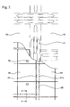
Figure 2 is a partial plan view of a double-barrier for a land-based liquefied gas storage tank in accordance with one embodiment of the present disclosure; and -
Figure 3 is a partially cross-sectional view taken along line A-A ofFigure 2 . - Embodiments of the present disclosure will now be described in detail with reference to the accompanying drawings.
- Referring to
Figures 2 and3 , a double-barrier for a land-based liquefied gas storage tank includes asealing wall 10 as a primary barrier which direct contacts a liquefied gas stored in the storage tank, and aninsulating wall 20 as a secondary barrier which is disposed between atank body 3 and the sealingwall 10 to prevent heat-transfer from an exterior of the tank and leakage of the liquefied gas. - The
sealing wall 10, i.e. the primary barrier, is continuously formed of a metallic material such as SUS and the like, which can endure cryogenic conditions inside the storage tank. The sealingwall 10 may be formed withfolds 11 to absorb thermal deformation of the storage tank which occurs during receipt of the liquefied gas. - The
insulating wall 20 as the secondary barrier includesprimary insulating panels 21 disposed outside the sealing wall 10 (i.e. an opposite side to the surface contacting the liquefied gas) andsecondary insulating panels 25 disposed on thetank body 3. Herein, the term "inside" means a direction towards an inner space of the storage tank in which liquefied gas is stored, and the term "outside" means an opposite direction. - The primary and secondary
insulating panels Figure 3 , theprotection layer 21a is shown as being disposed only on the inner surface of the primary insulating panel 21). - A
glass cloth 29 may, for example, be disposed between theprimary insulting panel 21 and thesecondary insulating panel 25. Theglass cloth 29 can be attached to the insulating panel in a PU bonding manner. - The plural
secondary insulating panels 25 may be stacked on the inner surface of thetank body 3, and thetank body 3 may be provided with ananchor member 3a to couple thesecondary insulating panels 25 to thetank body 3. - The
secondary insulating panels 25 may be separated from each other to define asecondary gap 26 between adjacent secondaryinsulating panels 25. In thesecondary gap 26, as described below, a polyurethane-based insulating material may be foamed by injection via afilling hole 21b formed through theprimary insulating panel 21. A fillingmember 21 b, which is formed in thesecondary gap 26 by foaming the insulating material, reliably prevents the liquefied gas from leaking outside via the insulatingwall 20 even when leakage of the liquefied gas occurs due to breakage of the sealingwall 10, thereby allowing theinsulating wall 20 to serve as the secondary barrier. - Inside the
secondary insulating panels 25, theprimary insulating panels 21 are stacked to be separated from each other to define aprimary gap 22 between adjacentprimary insulating panels 21 as in thesecondary insulating panels 25. Theprimary gap 22 may be filled with aninsulator 23 such as glass wool. - The
primary insulating panels 21 and thesecondary insulating panels 25 may be arranged in a different way such that thesecondary gap 26 between thesecondary insulating panels 25 and theprimary gap 22 between theprimary insulating panels 21 are formed at different locations, as shown inFigure 3 . - In order to form the
filling member 27 by injection-molding the polyurethane-based insulating material in thesecondary gap 26 between thesecondary insulating panels 25, as shown inFigure 2 , the primaryinsulating panel 21 is formed with a plurality offilling holes 21 b separated at constant intervals from each other along thesecondary gap 26. - When injection-molding the insulating material into the
secondary gap 26 to form thefilling member 27, an operator can check how far filling of the insulating material into thesecondary gap 26 has proceeded via anotherfilling hole 21b adjacent to thefilling hole 21b through which the insulating material is injected. - As described above, the polyurethane foam insulating material may be foamed in the
secondary gap 26 via thefilling hole 21b of theprimary insulating panel 21. Here, an adhesive may be deposited between side surfaces of thesecondary insulating panels 25 such that thefoamed filling member 27 closely adheres to the side surfaces of thesecondary insulating panels 25. - If the sealing
wall 10 serving as the primary barrier is broken so as to cause leakage of the liquefied gas, the gas can flow towards thesecondary gap 26 via theprimary gap 22 and a gap between the primary and secondaryinsulating panels secondary insulating panel 25 is higher than a liquefaction temperature of the liquefied gas, the leaking solution is vaporized, thereby increasing pressure in thesecondary gap 26. Since thesecondary gap 26 is a closed space defined by theprimary insulating panel 21, thesecondary insulating panel 25, and thetank body 3, such an increase in pressure of thesecondary gap 26 can restrict a flow of leaking solution into thesecondary gap 26. - Even if leakage occurs as such and the leaking solution flows into the
secondary gap 26, vaporization of the liquefied gas, which has previously leaked, causes an increase in pressure to prevent the leaking solution from continuously flowing, thereby allowing the insulating wall to serve as the secondary barrier. - As described above, according to the embodiment, in constructing one of two insulating layers (i.e. the secondary insulating layer near the concrete tank body undergoing minor thermal expansion), the same material as the insulating panels, which constitute the insulating layer, is foamed in-situ between the respective insulating panels (i.e. the secondary insulating panels), so that the insulating panels as well as the insulating panel and the concrete wall (i.e. tank body) can be integrated with each other. Therefore, the integrated insulating panels and the integrated insulating panel and concrete wall serve as the secondary barrier for preventing leakage of the liquefied gas.
- Moreover, even when a crack is created in the secondary barrier, leakage of the liquefied gas can be sufficiently restricted because the insulating wall (i.e. the secondary insulating layer) is integrated with the concrete wall and because the leaking liquefied gas is vaporized due to a higher temperature of the concrete wall than the liquefaction temperature and causes an increase in pressure around the crack. Therefore, a very low temperature is not transferred through the tank body to prevent damage of the storage tank.
- As described above, the secondary insulating panels are bonded together by foaming the same insulating material as the secondary insulating panel in-situ, and an adhesive or like may be applied onto the lateral side of the insulating panel so as not to create crack in the boundary between the foam insulating material and the insulating panel.
- As such, according to the embodiments, leakage of a liquefied gas can be doubly prevented by the construction of the sealing and insulating walls which are attached inside the tank body.
- Further, since there is no need for additional installation of a secondary barrier outside the storage tank, a space for a single storage tank is reduced and thus more storage tanks can be installed in the same space, which is advantageous in reduction in cost, time and efforts in construction of the storage tank.
- The various embodiments described above can be combined to provide further embodiments. All patents, patent application publications, patent applications, and non-patent publications referred to in this specification and/or listed in the Application Data Sheet are incorporated herein by reference, in their entirety. Aspects of the embodiments can be modified, if necessary, to employ concepts of the various patents, applications and publications to provide yet further embodiments.
- These and other changes can be made to the embodiments in light of the above-detailed description. In general, in the following claims, the terms used should not be construed to limit the claims to the specific embodiments disclosed in the specification and the claims, but should be construed to include all possible embodiments along with the full scope of equivalents to which such claims are entitled. Accordingly, the claims are not limited by the disclosure.
Claims (6)
- A double-barrier for a land-based liquefied gas storage tank comprising:an insulating wall (20) inside a tank body (3) of the storage tank, the insulating wall (20) comprising a plurality of insulating panels attached to the tank body and separated from each other;a sealing wall (10) disposed inside the insulating wall (20) to primarily prevent leakage of a liquefied gas while directly contacting the liquefied gas in the storage tank; andthe insulating wall (20) comprising a plurality of primary insulating panels (21) disposed outside the sealing wall (10) and a plurality of secondary insulating panels (25) disposed on the tank body (3), the double-barrier is characterized in that,a space between the insulating panels is filled with an insulating material to secondarily prevent leakage of the liquefied gas;the secondary insulating panels (25) are disposed to define a secondary gap (26) between adjacent secondary insulating panels (25), and the insulating material (27) is injected into the secondary gap (26) and foamed in the secondary gap (26); andthe same material as the secondary insulating panels (25) is foamed in the secondary gap (26) so that the secondary insulating panels (25) are integrated with each other.
- The double-barrier according to claim 1, wherein the primary insulating panels (21) are disposed to define a primary gap (22) between adjacent primary insulating panels, and an insulator (23) is inserted into the primary gap.
- The double-barrier according to claim 1, wherein a glass cloth (29) is interposed between the primary insulating panel (21) and the secondary insulating panel (25).
- The double-barrier according to claim 2, wherein the secondary insulating panels (25) are disposed to define a secondary gap (26) between adjacent secondary insulating panels, and the primary insulating panels (21) and the secondary insulating panels (25) are disposed to define the primary gap (22) and the secondary gap (26) at different locations.
- The double-barrier according to claim 4, wherein the primary insulating panel (21) comprises a plurality of filling holes (21 b) formed at a location corresponding to the secondary gap (26) to allow the insulating material (27) to be injected into the secondary gap (26).
- The double-barrier according to claim 1, wherein the insulating panel and the insulating material comprise polyurethane foam, and an adhesive is applied to a lateral side of the insulating panel to facilitate attachment of the insulating material thereto.
Applications Claiming Priority (1)
| Application Number | Priority Date | Filing Date | Title |
|---|---|---|---|
| KR1020090106532A KR20110051299A (en) | 2009-11-05 | 2009-11-05 | Double barrier of land liquefied gas storage tank and its formation method |
Publications (2)
| Publication Number | Publication Date |
|---|---|
| EP2320123A1 EP2320123A1 (en) | 2011-05-11 |
| EP2320123B1 true EP2320123B1 (en) | 2012-10-31 |
Family
ID=41581012
Family Applications (1)
| Application Number | Title | Priority Date | Filing Date |
|---|---|---|---|
| EP09014705A Not-in-force EP2320123B1 (en) | 2009-11-05 | 2009-11-25 | Double barrier for liquefied gas storage tank and method of constructing the same |
Country Status (5)
| Country | Link |
|---|---|
| EP (1) | EP2320123B1 (en) |
| JP (1) | JP5033169B2 (en) |
| KR (1) | KR20110051299A (en) |
| CN (1) | CN102052559B (en) |
| AU (1) | AU2009238346B2 (en) |
Families Citing this family (15)
| Publication number | Priority date | Publication date | Assignee | Title |
|---|---|---|---|---|
| CN102213361B (en) * | 2011-05-30 | 2012-11-14 | 中国寰球工程公司 | Liquid ethylene storage tank, liquid ethylene storage and gasification system and liquid ethylene gasification method |
| FR2987100B1 (en) * | 2012-02-20 | 2015-04-10 | Gaztransp Et Technigaz | CALORIFYING ELEMENTS FOR SEALED AND THERMALLY INSULATED TANKS |
| KR101599284B1 (en) * | 2014-05-30 | 2016-03-03 | 삼성중공업 주식회사 | Tank for liquid fuel gas |
| CN104061433B (en) * | 2014-06-30 | 2016-01-13 | 武汉一冶钢结构有限责任公司 | Outer tank nesting method in a kind of small-sized LNG double-layer tank |
| KR20160036837A (en) * | 2014-09-26 | 2016-04-05 | 대우조선해양 주식회사 | Boil-off Rate Reduction Method for Liquified Natural Gas Storage Tank |
| CN105523309B (en) * | 2014-09-29 | 2018-09-25 | 江南造船(集团)有限责任公司 | A kind of insulation system of Type B independent liquid cargo tank on liquefied gas carrier |
| JP2017132473A (en) * | 2016-01-25 | 2017-08-03 | 株式会社Ihi | Double shell tank |
| CN107795845B (en) * | 2016-09-05 | 2023-12-22 | 张家港中集圣达因低温装备有限公司 | Three-layer metal wall full-containing storage tank |
| GB2554862A (en) * | 2016-10-04 | 2018-04-18 | Torgy Lng Holding As | Secondary barrier system |
| CN107420736A (en) * | 2017-08-02 | 2017-12-01 | 酷泰克保温科技江苏有限公司 | A kind of cryogenic storage tank fire lagging |
| FR3077764B1 (en) * | 2018-02-09 | 2020-01-17 | Gaztransport Et Technigaz | PROCESS FOR MANUFACTURING A WATERPROOF AND THERMALLY INSULATING TANK WALL COMPRISING INTER-PANEL INSULATING CAPS |
| NO346027B1 (en) * | 2020-07-09 | 2022-01-10 | Lnt Marine Pte Ltd | Method for applying insulation to a combined cylindrical tank, a combined cylindrical tank and use thereof |
| WO2022215829A1 (en) * | 2021-04-08 | 2022-10-13 | 현대중공업 주식회사 | Liquefied gas storage tank and ship comprising same |
| FR3127486B1 (en) * | 2021-09-30 | 2023-11-24 | Gaztransport Et Technigaz | Process for insulating an inter-panel space |
| CN120332647B (en) * | 2025-06-17 | 2025-08-22 | 中太能源科技(上海)有限公司 | Liquefied gas storage equipment and assembly method thereof |
Family Cites Families (15)
| Publication number | Priority date | Publication date | Assignee | Title |
|---|---|---|---|---|
| US3773604A (en) * | 1971-02-10 | 1973-11-20 | Balsa Ecuador Lumber Corp | Structural light-weight panel of high strength,having theral insulation properties and enclosures formed thereby |
| GB1436109A (en) * | 1972-08-10 | 1976-05-19 | Marine Ind Developments Ltd | Storage tanks particularly for liquefied gases |
| US3931424A (en) * | 1973-12-13 | 1976-01-06 | Rockwell International Corporation | Prefabricated thermal insulation structure and method |
| US4116150A (en) * | 1976-03-09 | 1978-09-26 | Mcdonnell Douglas Corporation | Cryogenic insulation system |
| US4170952A (en) * | 1976-03-09 | 1979-10-16 | Mcdonnell Douglas Corporation | Cryogenic insulation system |
| FR2398961A1 (en) | 1977-07-26 | 1979-02-23 | Gaz Transport | THERMALLY INSULATED TANK FOR THE GROUND STORAGE OF LOW TEMPERATURE LIQUID, IN PARTICULAR LIQUEFIED NATURAL GAS |
| DE3717020A1 (en) * | 1987-05-21 | 1988-12-08 | Willich F Gmbh & Co | Process for the opening-free production of pipe insulations, and cold-insulated pipeline |
| FR2739675B1 (en) | 1995-10-05 | 1997-11-07 | Gaztransport Et Technigaz | LAND TANK FOR LOW TEMPERATURE LIQUID STORAGE |
| FR2861060B1 (en) * | 2003-10-16 | 2006-01-06 | Gaz Transport & Technigaz | WATERPROOF STRUCTURE AND TANK PROVIDED WITH SUCH A STRUCTURE |
| JP2006017213A (en) * | 2004-07-01 | 2006-01-19 | Ishikawajima Harima Heavy Ind Co Ltd | Cold seal structure of cryogenic fluid storage tank |
| DE602004023657D1 (en) * | 2004-08-04 | 2009-11-26 | Ootmarsum Harry Robert Van | MEMORY CONTAINER FOR COLD LIQUIDS AND METHOD FOR INSTALLING A HEAT INSULATION SYSTEM IN SUCH A CONTAINER |
| CN100453402C (en) * | 2004-12-08 | 2009-01-21 | 韩国Gas公社 | Liquefied natural gas storage tank and manufacturing method thereof |
| KR100499710B1 (en) * | 2004-12-08 | 2005-07-05 | 한국가스공사 | Lng storage tank installed inside the ship and manufacturing method the tank |
| KR100644217B1 (en) * | 2006-04-20 | 2006-11-10 | 한국가스공사 | LNG storage tank with improved insulation structure and its manufacturing method |
| CN101688640B (en) * | 2007-05-29 | 2011-06-08 | 现代重工业株式会社 | Liquefied natural gas storage tank insulation system with welded secondary walls and method of construction |
-
2009
- 2009-11-05 KR KR1020090106532A patent/KR20110051299A/en not_active Ceased
- 2009-11-20 AU AU2009238346A patent/AU2009238346B2/en not_active Ceased
- 2009-11-24 JP JP2009266687A patent/JP5033169B2/en not_active Expired - Fee Related
- 2009-11-25 EP EP09014705A patent/EP2320123B1/en not_active Not-in-force
- 2009-11-25 CN CN2009102241285A patent/CN102052559B/en not_active Expired - Fee Related
Also Published As
| Publication number | Publication date |
|---|---|
| CN102052559A (en) | 2011-05-11 |
| JP5033169B2 (en) | 2012-09-26 |
| CN102052559B (en) | 2013-08-07 |
| KR20110051299A (en) | 2011-05-18 |
| AU2009238346A1 (en) | 2011-05-19 |
| AU2009238346B2 (en) | 2012-09-13 |
| JP2011099548A (en) | 2011-05-19 |
| EP2320123A1 (en) | 2011-05-11 |
Similar Documents
| Publication | Publication Date | Title |
|---|---|---|
| EP2320123A1 (en) | Double barrier for liquefied gas storage tank and method of constructing the same | |
| KR102613681B1 (en) | liquefied gas tank and ship having the same | |
| KR102082501B1 (en) | Liquid cargo storage tank and marine structure including the same | |
| JP2006017213A (en) | Cold seal structure of cryogenic fluid storage tank | |
| KR101454619B1 (en) | Cargo for liquefied gas and unloading method using the same | |
| JP6036605B2 (en) | Above-ground cryogenic tank | |
| KR102129561B1 (en) | Insulation structure and liquefied gas storage tank having the same | |
| KR101843863B1 (en) | Insulation structure of independent type storage tank and manufacturing method thereof | |
| KR102947422B1 (en) | Insulation structure for liquified gas storage tank and method for forming the insulation structure | |
| KR102351594B1 (en) | Insulation Box Of Cargo Tank And Manufacturing Method Of The Same | |
| KR20130045500A (en) | Insulation structure for pump tower of lng tank | |
| AU2024276776A1 (en) | Ground-type storage tank | |
| RU2812099C2 (en) | Thermal barrier for tank wall | |
| KR102785264B1 (en) | Insulation Box Reinforcement Structure of Liquefied Gas Storage Tank | |
| RU2860423C2 (en) | Sealed and heat-insulating tank including corrugation blocking device | |
| KR20120057528A (en) | Liquefied gas storage tank | |
| KR102608693B1 (en) | Lower barrier structure of independence type storage tank | |
| KR102785265B1 (en) | Insulation Box Reinforcement Structure of Liquefied Gas Storage Tank | |
| KR101103879B1 (en) | Independent cargo tank with double barrier structure | |
| KR200462376Y1 (en) | Insulation structure of a liquified gas storage tank | |
| AU2024275714A1 (en) | Low-temperature storage tank | |
| KR20240116353A (en) | Liquefied gas storage tank | |
| KR20240076740A (en) | Insulation member and liquefied gas storage tank including the same | |
| RU2788778C2 (en) | Wall of a heat-insulating and hermetic tank | |
| KR20220013261A (en) | Liquefied gas storage tank and vessel comprising the same |
Legal Events
| Date | Code | Title | Description |
|---|---|---|---|
| PUAI | Public reference made under article 153(3) epc to a published international application that has entered the european phase |
Free format text: ORIGINAL CODE: 0009012 |
|
| 17P | Request for examination filed |
Effective date: 20091125 |
|
| AK | Designated contracting states |
Kind code of ref document: A1 Designated state(s): AT BE BG CH CY CZ DE DK EE ES FI FR GB GR HR HU IE IS IT LI LT LU LV MC MK MT NL NO PL PT RO SE SI SK SM TR |
|
| AX | Request for extension of the european patent |
Extension state: AL BA RS |
|
| GRAP | Despatch of communication of intention to grant a patent |
Free format text: ORIGINAL CODE: EPIDOSNIGR1 |
|
| RIC1 | Information provided on ipc code assigned before grant |
Ipc: F17C 13/00 20060101ALI20120416BHEP Ipc: F17C 1/12 20060101AFI20120416BHEP Ipc: F17C 3/02 20060101ALI20120416BHEP |
|
| GRAS | Grant fee paid |
Free format text: ORIGINAL CODE: EPIDOSNIGR3 |
|
| GRAA | (expected) grant |
Free format text: ORIGINAL CODE: 0009210 |
|
| AK | Designated contracting states |
Kind code of ref document: B1 Designated state(s): AT BE BG CH CY CZ DE DK EE ES FI FR GB GR HR HU IE IS IT LI LT LU LV MC MK MT NL NO PL PT RO SE SI SK SM TR |
|
| REG | Reference to a national code |
Ref country code: GB Ref legal event code: FG4D Ref country code: CH Ref legal event code: EP |
|
| REG | Reference to a national code |
Ref country code: AT Ref legal event code: REF Ref document number: 582222 Country of ref document: AT Kind code of ref document: T Effective date: 20121115 |
|
| REG | Reference to a national code |
Ref country code: IE Ref legal event code: FG4D |
|
| REG | Reference to a national code |
Ref country code: DE Ref legal event code: R096 Ref document number: 602009010752 Country of ref document: DE Effective date: 20121227 |
|
| REG | Reference to a national code |
Ref country code: AT Ref legal event code: MK05 Ref document number: 582222 Country of ref document: AT Kind code of ref document: T Effective date: 20121031 |
|
| REG | Reference to a national code |
Ref country code: LT Ref legal event code: MG4D |
|
| REG | Reference to a national code |
Ref country code: GR Ref legal event code: EP Ref document number: 20130400157 Country of ref document: GR Effective date: 20130225 |
|
| REG | Reference to a national code |
Ref country code: NL Ref legal event code: VDEP Effective date: 20121031 |
|
| PG25 | Lapsed in a contracting state [announced via postgrant information from national office to epo] |
Ref country code: SE Free format text: LAPSE BECAUSE OF FAILURE TO SUBMIT A TRANSLATION OF THE DESCRIPTION OR TO PAY THE FEE WITHIN THE PRESCRIBED TIME-LIMIT Effective date: 20121031 Ref country code: NO Free format text: LAPSE BECAUSE OF FAILURE TO SUBMIT A TRANSLATION OF THE DESCRIPTION OR TO PAY THE FEE WITHIN THE PRESCRIBED TIME-LIMIT Effective date: 20130131 Ref country code: HR Free format text: LAPSE BECAUSE OF FAILURE TO SUBMIT A TRANSLATION OF THE DESCRIPTION OR TO PAY THE FEE WITHIN THE PRESCRIBED TIME-LIMIT Effective date: 20121031 Ref country code: IS Free format text: LAPSE BECAUSE OF FAILURE TO SUBMIT A TRANSLATION OF THE DESCRIPTION OR TO PAY THE FEE WITHIN THE PRESCRIBED TIME-LIMIT Effective date: 20130228 Ref country code: NL Free format text: LAPSE BECAUSE OF FAILURE TO SUBMIT A TRANSLATION OF THE DESCRIPTION OR TO PAY THE FEE WITHIN THE PRESCRIBED TIME-LIMIT Effective date: 20121031 Ref country code: ES Free format text: LAPSE BECAUSE OF FAILURE TO SUBMIT A TRANSLATION OF THE DESCRIPTION OR TO PAY THE FEE WITHIN THE PRESCRIBED TIME-LIMIT Effective date: 20130211 Ref country code: FI Free format text: LAPSE BECAUSE OF FAILURE TO SUBMIT A TRANSLATION OF THE DESCRIPTION OR TO PAY THE FEE WITHIN THE PRESCRIBED TIME-LIMIT Effective date: 20121031 Ref country code: LT Free format text: LAPSE BECAUSE OF FAILURE TO SUBMIT A TRANSLATION OF THE DESCRIPTION OR TO PAY THE FEE WITHIN THE PRESCRIBED TIME-LIMIT Effective date: 20121031 |
|
| PG25 | Lapsed in a contracting state [announced via postgrant information from national office to epo] |
Ref country code: LV Free format text: LAPSE BECAUSE OF FAILURE TO SUBMIT A TRANSLATION OF THE DESCRIPTION OR TO PAY THE FEE WITHIN THE PRESCRIBED TIME-LIMIT Effective date: 20121031 Ref country code: PL Free format text: LAPSE BECAUSE OF FAILURE TO SUBMIT A TRANSLATION OF THE DESCRIPTION OR TO PAY THE FEE WITHIN THE PRESCRIBED TIME-LIMIT Effective date: 20121031 Ref country code: BE Free format text: LAPSE BECAUSE OF FAILURE TO SUBMIT A TRANSLATION OF THE DESCRIPTION OR TO PAY THE FEE WITHIN THE PRESCRIBED TIME-LIMIT Effective date: 20121031 Ref country code: SI Free format text: LAPSE BECAUSE OF FAILURE TO SUBMIT A TRANSLATION OF THE DESCRIPTION OR TO PAY THE FEE WITHIN THE PRESCRIBED TIME-LIMIT Effective date: 20121031 Ref country code: PT Free format text: LAPSE BECAUSE OF FAILURE TO SUBMIT A TRANSLATION OF THE DESCRIPTION OR TO PAY THE FEE WITHIN THE PRESCRIBED TIME-LIMIT Effective date: 20130228 |
|
| PG25 | Lapsed in a contracting state [announced via postgrant information from national office to epo] |
Ref country code: AT Free format text: LAPSE BECAUSE OF FAILURE TO SUBMIT A TRANSLATION OF THE DESCRIPTION OR TO PAY THE FEE WITHIN THE PRESCRIBED TIME-LIMIT Effective date: 20121031 |
|
| PG25 | Lapsed in a contracting state [announced via postgrant information from national office to epo] |
Ref country code: CZ Free format text: LAPSE BECAUSE OF FAILURE TO SUBMIT A TRANSLATION OF THE DESCRIPTION OR TO PAY THE FEE WITHIN THE PRESCRIBED TIME-LIMIT Effective date: 20121031 Ref country code: BG Free format text: LAPSE BECAUSE OF FAILURE TO SUBMIT A TRANSLATION OF THE DESCRIPTION OR TO PAY THE FEE WITHIN THE PRESCRIBED TIME-LIMIT Effective date: 20130131 Ref country code: SK Free format text: LAPSE BECAUSE OF FAILURE TO SUBMIT A TRANSLATION OF THE DESCRIPTION OR TO PAY THE FEE WITHIN THE PRESCRIBED TIME-LIMIT Effective date: 20121031 Ref country code: EE Free format text: LAPSE BECAUSE OF FAILURE TO SUBMIT A TRANSLATION OF THE DESCRIPTION OR TO PAY THE FEE WITHIN THE PRESCRIBED TIME-LIMIT Effective date: 20121031 Ref country code: DK Free format text: LAPSE BECAUSE OF FAILURE TO SUBMIT A TRANSLATION OF THE DESCRIPTION OR TO PAY THE FEE WITHIN THE PRESCRIBED TIME-LIMIT Effective date: 20121031 |
|
| REG | Reference to a national code |
Ref country code: IE Ref legal event code: MM4A |
|
| PG25 | Lapsed in a contracting state [announced via postgrant information from national office to epo] |
Ref country code: IT Free format text: LAPSE BECAUSE OF FAILURE TO SUBMIT A TRANSLATION OF THE DESCRIPTION OR TO PAY THE FEE WITHIN THE PRESCRIBED TIME-LIMIT Effective date: 20121031 Ref country code: RO Free format text: LAPSE BECAUSE OF FAILURE TO SUBMIT A TRANSLATION OF THE DESCRIPTION OR TO PAY THE FEE WITHIN THE PRESCRIBED TIME-LIMIT Effective date: 20121031 |
|
| PLBE | No opposition filed within time limit |
Free format text: ORIGINAL CODE: 0009261 |
|
| STAA | Information on the status of an ep patent application or granted ep patent |
Free format text: STATUS: NO OPPOSITION FILED WITHIN TIME LIMIT |
|
| REG | Reference to a national code |
Ref country code: DE Ref legal event code: R119 Ref document number: 602009010752 Country of ref document: DE Effective date: 20130601 |
|
| 26N | No opposition filed |
Effective date: 20130801 |
|
| PG25 | Lapsed in a contracting state [announced via postgrant information from national office to epo] |
Ref country code: IE Free format text: LAPSE BECAUSE OF NON-PAYMENT OF DUE FEES Effective date: 20121125 Ref country code: DE Free format text: LAPSE BECAUSE OF NON-PAYMENT OF DUE FEES Effective date: 20130601 |
|
| PG25 | Lapsed in a contracting state [announced via postgrant information from national office to epo] |
Ref country code: MT Free format text: LAPSE BECAUSE OF FAILURE TO SUBMIT A TRANSLATION OF THE DESCRIPTION OR TO PAY THE FEE WITHIN THE PRESCRIBED TIME-LIMIT Effective date: 20121031 Ref country code: CY Free format text: LAPSE BECAUSE OF FAILURE TO SUBMIT A TRANSLATION OF THE DESCRIPTION OR TO PAY THE FEE WITHIN THE PRESCRIBED TIME-LIMIT Effective date: 20121031 |
|
| PG25 | Lapsed in a contracting state [announced via postgrant information from national office to epo] |
Ref country code: TR Free format text: LAPSE BECAUSE OF FAILURE TO SUBMIT A TRANSLATION OF THE DESCRIPTION OR TO PAY THE FEE WITHIN THE PRESCRIBED TIME-LIMIT Effective date: 20121031 Ref country code: MC Free format text: LAPSE BECAUSE OF NON-PAYMENT OF DUE FEES Effective date: 20121130 |
|
| PG25 | Lapsed in a contracting state [announced via postgrant information from national office to epo] |
Ref country code: SM Free format text: LAPSE BECAUSE OF FAILURE TO SUBMIT A TRANSLATION OF THE DESCRIPTION OR TO PAY THE FEE WITHIN THE PRESCRIBED TIME-LIMIT Effective date: 20121031 Ref country code: LU Free format text: LAPSE BECAUSE OF NON-PAYMENT OF DUE FEES Effective date: 20121125 |
|
| REG | Reference to a national code |
Ref country code: CH Ref legal event code: PL |
|
| GBPC | Gb: european patent ceased through non-payment of renewal fee |
Effective date: 20131125 |
|
| PG25 | Lapsed in a contracting state [announced via postgrant information from national office to epo] |
Ref country code: LI Free format text: LAPSE BECAUSE OF NON-PAYMENT OF DUE FEES Effective date: 20131130 Ref country code: HU Free format text: LAPSE BECAUSE OF FAILURE TO SUBMIT A TRANSLATION OF THE DESCRIPTION OR TO PAY THE FEE WITHIN THE PRESCRIBED TIME-LIMIT Effective date: 20091125 Ref country code: CH Free format text: LAPSE BECAUSE OF NON-PAYMENT OF DUE FEES Effective date: 20131130 |
|
| PG25 | Lapsed in a contracting state [announced via postgrant information from national office to epo] |
Ref country code: GB Free format text: LAPSE BECAUSE OF NON-PAYMENT OF DUE FEES Effective date: 20131125 |
|
| PG25 | Lapsed in a contracting state [announced via postgrant information from national office to epo] |
Ref country code: MK Free format text: LAPSE BECAUSE OF FAILURE TO SUBMIT A TRANSLATION OF THE DESCRIPTION OR TO PAY THE FEE WITHIN THE PRESCRIBED TIME-LIMIT Effective date: 20121031 |
|
| REG | Reference to a national code |
Ref country code: FR Ref legal event code: PLFP Year of fee payment: 7 |
|
| REG | Reference to a national code |
Ref country code: FR Ref legal event code: TQ Owner name: DAEWOO SHIPBUILDING & MARINE ENGINEERING., LTD, KR Effective date: 20160426 Ref country code: FR Ref legal event code: TQ Owner name: HYUNDAI HEAVY INDUSTRIES CO., LTD., KR Effective date: 20160426 Ref country code: FR Ref legal event code: TQ Owner name: KOREA GAS CORPORATION, KR Effective date: 20160426 Ref country code: FR Ref legal event code: TQ Owner name: SAMSUNG HEAVY INDUSTRIES CO., LTD., KR Effective date: 20160426 |
|
| REG | Reference to a national code |
Ref country code: FR Ref legal event code: PLFP Year of fee payment: 8 |
|
| REG | Reference to a national code |
Ref country code: FR Ref legal event code: PLFP Year of fee payment: 9 |
|
| REG | Reference to a national code |
Ref country code: FR Ref legal event code: TP Owner name: KC LNG TECH CO., LTD., KR Effective date: 20180115 |
|
| PGFP | Annual fee paid to national office [announced via postgrant information from national office to epo] |
Ref country code: FR Payment date: 20191121 Year of fee payment: 11 Ref country code: GR Payment date: 20191120 Year of fee payment: 11 |
|
| PG25 | Lapsed in a contracting state [announced via postgrant information from national office to epo] |
Ref country code: GR Free format text: LAPSE BECAUSE OF NON-PAYMENT OF DUE FEES Effective date: 20210608 |
|
| PG25 | Lapsed in a contracting state [announced via postgrant information from national office to epo] |
Ref country code: FR Free format text: LAPSE BECAUSE OF NON-PAYMENT OF DUE FEES Effective date: 20201130 |