EP2320110A1 - Control system for a vehicle having a transmission with autoshift function - Google Patents
Control system for a vehicle having a transmission with autoshift function Download PDFInfo
- Publication number
- EP2320110A1 EP2320110A1 EP10189255A EP10189255A EP2320110A1 EP 2320110 A1 EP2320110 A1 EP 2320110A1 EP 10189255 A EP10189255 A EP 10189255A EP 10189255 A EP10189255 A EP 10189255A EP 2320110 A1 EP2320110 A1 EP 2320110A1
- Authority
- EP
- European Patent Office
- Prior art keywords
- engine speed
- control means
- engine
- setting
- manual control
- Prior art date
- Legal status (The legal status is an assumption and is not a legal conclusion. Google has not performed a legal analysis and makes no representation as to the accuracy of the status listed.)
- Granted
Links
Images



Classifications
-
- B—PERFORMING OPERATIONS; TRANSPORTING
- B60—VEHICLES IN GENERAL
- B60W—CONJOINT CONTROL OF VEHICLE SUB-UNITS OF DIFFERENT TYPE OR DIFFERENT FUNCTION; CONTROL SYSTEMS SPECIALLY ADAPTED FOR HYBRID VEHICLES; ROAD VEHICLE DRIVE CONTROL SYSTEMS FOR PURPOSES NOT RELATED TO THE CONTROL OF A PARTICULAR SUB-UNIT
- B60W50/00—Details of control systems for road vehicle drive control not related to the control of a particular sub-unit, e.g. process diagnostic or vehicle driver interfaces
- B60W50/08—Interaction between the driver and the control system
- B60W50/085—Changing the parameters of the control units, e.g. changing limit values, working points by control input
-
- B—PERFORMING OPERATIONS; TRANSPORTING
- B60—VEHICLES IN GENERAL
- B60W—CONJOINT CONTROL OF VEHICLE SUB-UNITS OF DIFFERENT TYPE OR DIFFERENT FUNCTION; CONTROL SYSTEMS SPECIALLY ADAPTED FOR HYBRID VEHICLES; ROAD VEHICLE DRIVE CONTROL SYSTEMS FOR PURPOSES NOT RELATED TO THE CONTROL OF A PARTICULAR SUB-UNIT
- B60W10/00—Conjoint control of vehicle sub-units of different type or different function
- B60W10/04—Conjoint control of vehicle sub-units of different type or different function including control of propulsion units
- B60W10/06—Conjoint control of vehicle sub-units of different type or different function including control of propulsion units including control of combustion engines
-
- B—PERFORMING OPERATIONS; TRANSPORTING
- B60—VEHICLES IN GENERAL
- B60W—CONJOINT CONTROL OF VEHICLE SUB-UNITS OF DIFFERENT TYPE OR DIFFERENT FUNCTION; CONTROL SYSTEMS SPECIALLY ADAPTED FOR HYBRID VEHICLES; ROAD VEHICLE DRIVE CONTROL SYSTEMS FOR PURPOSES NOT RELATED TO THE CONTROL OF A PARTICULAR SUB-UNIT
- B60W10/00—Conjoint control of vehicle sub-units of different type or different function
- B60W10/10—Conjoint control of vehicle sub-units of different type or different function including control of change-speed gearings
- B60W10/11—Stepped gearings
-
- B—PERFORMING OPERATIONS; TRANSPORTING
- B60—VEHICLES IN GENERAL
- B60W—CONJOINT CONTROL OF VEHICLE SUB-UNITS OF DIFFERENT TYPE OR DIFFERENT FUNCTION; CONTROL SYSTEMS SPECIALLY ADAPTED FOR HYBRID VEHICLES; ROAD VEHICLE DRIVE CONTROL SYSTEMS FOR PURPOSES NOT RELATED TO THE CONTROL OF A PARTICULAR SUB-UNIT
- B60W30/00—Purposes of road vehicle drive control systems not related to the control of a particular sub-unit, e.g. of systems using conjoint control of vehicle sub-units
- B60W30/18—Propelling the vehicle
- B60W30/182—Selecting between different operative modes, e.g. comfort and performance modes
-
- B—PERFORMING OPERATIONS; TRANSPORTING
- B60—VEHICLES IN GENERAL
- B60W—CONJOINT CONTROL OF VEHICLE SUB-UNITS OF DIFFERENT TYPE OR DIFFERENT FUNCTION; CONTROL SYSTEMS SPECIALLY ADAPTED FOR HYBRID VEHICLES; ROAD VEHICLE DRIVE CONTROL SYSTEMS FOR PURPOSES NOT RELATED TO THE CONTROL OF A PARTICULAR SUB-UNIT
- B60W50/00—Details of control systems for road vehicle drive control not related to the control of a particular sub-unit, e.g. process diagnostic or vehicle driver interfaces
- B60W50/08—Interaction between the driver and the control system
- B60W50/082—Selecting or switching between different modes of propelling
-
- F—MECHANICAL ENGINEERING; LIGHTING; HEATING; WEAPONS; BLASTING
- F16—ENGINEERING ELEMENTS AND UNITS; GENERAL MEASURES FOR PRODUCING AND MAINTAINING EFFECTIVE FUNCTIONING OF MACHINES OR INSTALLATIONS; THERMAL INSULATION IN GENERAL
- F16H—GEARING
- F16H59/00—Control inputs to control units of change-speed- or reversing-gearings for conveying rotary motion
- F16H59/02—Selector apparatus
-
- F—MECHANICAL ENGINEERING; LIGHTING; HEATING; WEAPONS; BLASTING
- F16—ENGINEERING ELEMENTS AND UNITS; GENERAL MEASURES FOR PRODUCING AND MAINTAINING EFFECTIVE FUNCTIONING OF MACHINES OR INSTALLATIONS; THERMAL INSULATION IN GENERAL
- F16H—GEARING
- F16H61/00—Control functions within control units of change-speed- or reversing-gearings for conveying rotary motion ; Control of exclusively fluid gearing, friction gearing, gearings with endless flexible members or other particular types of gearing
- F16H61/02—Control functions within control units of change-speed- or reversing-gearings for conveying rotary motion ; Control of exclusively fluid gearing, friction gearing, gearings with endless flexible members or other particular types of gearing characterised by the signals used
- F16H61/0202—Control functions within control units of change-speed- or reversing-gearings for conveying rotary motion ; Control of exclusively fluid gearing, friction gearing, gearings with endless flexible members or other particular types of gearing characterised by the signals used the signals being electric
- F16H61/0204—Control functions within control units of change-speed- or reversing-gearings for conveying rotary motion ; Control of exclusively fluid gearing, friction gearing, gearings with endless flexible members or other particular types of gearing characterised by the signals used the signals being electric for gearshift control, e.g. control functions for performing shifting or generation of shift signal
- F16H61/0213—Control functions within control units of change-speed- or reversing-gearings for conveying rotary motion ; Control of exclusively fluid gearing, friction gearing, gearings with endless flexible members or other particular types of gearing characterised by the signals used the signals being electric for gearshift control, e.g. control functions for performing shifting or generation of shift signal characterised by the method for generating shift signals
-
- B—PERFORMING OPERATIONS; TRANSPORTING
- B60—VEHICLES IN GENERAL
- B60W—CONJOINT CONTROL OF VEHICLE SUB-UNITS OF DIFFERENT TYPE OR DIFFERENT FUNCTION; CONTROL SYSTEMS SPECIALLY ADAPTED FOR HYBRID VEHICLES; ROAD VEHICLE DRIVE CONTROL SYSTEMS FOR PURPOSES NOT RELATED TO THE CONTROL OF A PARTICULAR SUB-UNIT
- B60W2540/00—Input parameters relating to occupants
- B60W2540/215—Selection or confirmation of options
-
- B—PERFORMING OPERATIONS; TRANSPORTING
- B60—VEHICLES IN GENERAL
- B60Y—INDEXING SCHEME RELATING TO ASPECTS CROSS-CUTTING VEHICLE TECHNOLOGY
- B60Y2200/00—Type of vehicle
- B60Y2200/20—Off-Road Vehicles
- B60Y2200/22—Agricultural vehicles
-
- F—MECHANICAL ENGINEERING; LIGHTING; HEATING; WEAPONS; BLASTING
- F16—ENGINEERING ELEMENTS AND UNITS; GENERAL MEASURES FOR PRODUCING AND MAINTAINING EFFECTIVE FUNCTIONING OF MACHINES OR INSTALLATIONS; THERMAL INSULATION IN GENERAL
- F16H—GEARING
- F16H59/00—Control inputs to control units of change-speed- or reversing-gearings for conveying rotary motion
- F16H59/02—Selector apparatus
- F16H2059/0221—Selector apparatus for selecting modes, e.g. sport, normal, economy
-
- F—MECHANICAL ENGINEERING; LIGHTING; HEATING; WEAPONS; BLASTING
- F16—ENGINEERING ELEMENTS AND UNITS; GENERAL MEASURES FOR PRODUCING AND MAINTAINING EFFECTIVE FUNCTIONING OF MACHINES OR INSTALLATIONS; THERMAL INSULATION IN GENERAL
- F16H—GEARING
- F16H61/00—Control functions within control units of change-speed- or reversing-gearings for conveying rotary motion ; Control of exclusively fluid gearing, friction gearing, gearings with endless flexible members or other particular types of gearing
- F16H61/02—Control functions within control units of change-speed- or reversing-gearings for conveying rotary motion ; Control of exclusively fluid gearing, friction gearing, gearings with endless flexible members or other particular types of gearing characterised by the signals used
- F16H61/0202—Control functions within control units of change-speed- or reversing-gearings for conveying rotary motion ; Control of exclusively fluid gearing, friction gearing, gearings with endless flexible members or other particular types of gearing characterised by the signals used the signals being electric
- F16H61/0204—Control functions within control units of change-speed- or reversing-gearings for conveying rotary motion ; Control of exclusively fluid gearing, friction gearing, gearings with endless flexible members or other particular types of gearing characterised by the signals used the signals being electric for gearshift control, e.g. control functions for performing shifting or generation of shift signal
- F16H61/0213—Control functions within control units of change-speed- or reversing-gearings for conveying rotary motion ; Control of exclusively fluid gearing, friction gearing, gearings with endless flexible members or other particular types of gearing characterised by the signals used the signals being electric for gearshift control, e.g. control functions for performing shifting or generation of shift signal characterised by the method for generating shift signals
- F16H2061/0227—Shift map selection, i.e. methods for controlling selection between different shift maps, e.g. to initiate switch to a map for up-hill driving
Definitions
- the present invention relates to vehicle control systems and more specifically to a control system for a vehicle having a transmission with autoshift functions.
- control system includes software implemented shifting logic which mainly is based on torque and engine speed to determine at what conditions an upshift or downshift of the transmission should occur on driving the vehicle.
- the conditions and parameters determining whether an upshift or downshift should be initiated by the control system are normally either set in the factory or may be changed by the user by re-programming the shifting control logic which mostly is a time consuming operation and cannot be done on the fly.
- the object of the present invention is to overcome the above disadvantages of the prior art by providing a control system and a method giving the driver easy and ready control over the autoshift function.
- a control system according to claim 1 is provided.
- a method for operating a vehicle control system is provided as defined in claim 9.
- two manual control means or two hand throttles are provided, the setting thereof giving a clear indication to the driver what the transmission will do in the autoshift mode.
- the operator may select one of a plurality of modes of operation in a simple and intuitive manner.
- the operator may select a first mode of operation, wherein a processor of the control system is caused to issue an upshift command to said transmission when the engine speed increases beyond said second engine speed setting and to issue a downshift command to said transmission when the engine speed decreases below said first engine speed setting.
- the processor may be adapted to continue with issuing upshift commands after the vehicle has reached said desired vehicle speed until the engine speed decreases to a value near but above the first engine speed.
- the operator may select a second mode of operation, wherein the processor is caused to issue power commands to said engine tending to maintain an existing gear setting, and to issue an upshift command to said transmission only when the engine speed increases beyond an upper engine speed threshold and to issue a downshift command to said transmission only when the engine speed decreases below a lower engine speed threshold.
- the operator may select a third mode of operation, wherein the processor is caused to issue power commands to said engine tending to maintain said first engine speed, and to issue a downshift command to said transmission only when the engine speed decreases below said second engine speed setting.
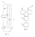
- FIG. 7 a general version of a vehicle control system 100 is shown.
- the vehicle (not shown) comprises an engine 102, preferably an internal combustion engine, which provides its output in the form of rotational motion at a given angular velocity to a transmission 104 which is provided with an autoshift function of a construction known in the art.
- Both the engine 102 and the transmission 104 provide signals representing operational conditions thereof to a processor 18 of the control system 100.
- the processor 18 in turn provides control signals to the engine 102 and the transmission 104.
- the processor 18 functions to select a desired engine speed from a range of engine speeds based on the required power output of the vehicle system.
- the control system 100 is designated for controlling engine speed of a vehicle system having an engine and a required power output, but may be used in any suitable environment.
- the control system 100 further comprises a user interface 10 coupled to the processor 18 and operative to provide control signals thereto as set out below in detail.
- Figs. 1 to 3 show an embodiment of the user interface 10.
- This user interface 10 comprises a first control 14 for manually setting a first engine speed and a second control 16 for manually setting a second engine speed.
- the controls 14, 16 may include a grip portion including geometry such as indents for fingers and a second material such as rubber to facilitate gripping or moving by hand or with fingers.
- the first control 14 and the second control 16 are sliding controls that can be slid along a linear path in a track, groove, or in any other suitable device or manner.
- An operator may slide the first sliding control 14 to a point on a graduation 20 such that the first sliding control designates a first engine speed A ( Figs. 4 to 6 ).
- the operator may slide the second sliding control 16 to a point on the graduation such that the second sliding control 16 designates second engine speed B.
- the first control 14 and the second control 16 may be located in the same track or groove, in separate tracks or grooves located near one another, in separate tracks or grooves located in different regions of the user interface, or in any other suitable configuration in any suitable region of the user interface.
- first and second controls 14, 16 may be levers that can be pivoted about an axis.
- the first control 14 and the second control 16 may be located on the same pivot point, located near one another in the same region of the user interface, located in different regions of the user interface, or in any other suitable configuration in any suitable region of the user interface.
- a further embodiment of the controls 14, 16 may comprise dials that can be rotated about an axis.
- the first control 14 and the second control 16 may include an arrow, a dot, a line, or any other suitable indicator on the dial, adjacent to the dial, or in both locations such that the operator may rotate the first control 14 and the second control 16 to a specific point to designate the first and second engine speeds, respectively.
- the dials of the first control 14 and the second control 16 may be located near one another in the same region of the user interface, located in different regions of the user interface, or in any other suitable configuration in any suitable region of the user interface. Additionally, the first and second dials may be concentrically located and rotate about the same axis.
- the first control 14 and the second control 16 are preferably standard dials and may be circular, polygonal (hexagonal, octagonal, etc.), rectangular or any other suitable geometry such that the operator may turn or rotate them.
- first control 14 and the second control 16 may be any other suitable device such that the first control 14 designates a first engine speed and the second control 16 designates a second engine speed.
- the selection of engine speeds allows the operator to base the speed of the engine on more than one parameter or function of the engine, such as power output, fuel efficiency, and noise signature.
- control system 100 may assume one of a plurality of modes of operation.
- a first mode of operation schematically shown in Fig. 4
- the operator may set, as a first engine speed A, a low engine speed with control 14 and as a second speed B, a high engine speed with control 16, as indicated in the upper part of Fig. 4 .
- the transmission will upshift when the engine reaches high engine speed setting B and will downshift when reaching the low engine speed setting A on the two controls or hand throttles.
- An economically oriented operator would upshift at quite low engine speed (about. 1700 to 1800 rpm of the engine) to save fuel he would use the highest possible gear.
- the downshift would occur when the engine can not capture the load anymore (about 1300 rpm of the engine).
- a second mode of operation is shown wherein controls 14, 16 are set to the same engine speed, so that the control system 100 tries to keep the transmission in the same gear until reaching a lower threshold LT when the load increases, resulting in a downshift.
- an upshift will occur when the load decreases and the engine speed reaches an upper threshold HT.
- the transmission will stay in gear since no threshold will be reached, as shown in the upper part of Fig. 5 .
- the first control 14 is set to a higher engine speed A than the second engine speed B set by the second control 16, as shown in the upper part of Fig. 6 .
- the first control 14 would set to an engine rotational speed A resulting in the desired PTO speed.
- the second control 16 would be set to a rotational speed lower than set by the first control 15 so that the transmission will shift down if the PTO load indicated in the lower part of Fig. 6 increases and the engine speed decreases below a rotational speed set by the second control 16.
- the transmission would shift up if the engine goes above the rotational speed set by the first control 14.
Landscapes
- Engineering & Computer Science (AREA)
- Mechanical Engineering (AREA)
- General Engineering & Computer Science (AREA)
- Chemical & Material Sciences (AREA)
- Combustion & Propulsion (AREA)
- Transportation (AREA)
- Automation & Control Theory (AREA)
- Human Computer Interaction (AREA)
- Control Of Transmission Device (AREA)
- Control Of Driving Devices And Active Controlling Of Vehicle (AREA)
Abstract
Description
- The present invention relates to vehicle control systems and more specifically to a control system for a vehicle having a transmission with autoshift functions.
- In vehicle control systems having a transmission with autoshift functions, the control system includes software implemented shifting logic which mainly is based on torque and engine speed to determine at what conditions an upshift or downshift of the transmission should occur on driving the vehicle.
- The conditions and parameters determining whether an upshift or downshift should be initiated by the control system are normally either set in the factory or may be changed by the user by re-programming the shifting control logic which mostly is a time consuming operation and cannot be done on the fly.
- Further, once the set up of the shifting points has been done, it is not readily recognizable what setting is in effect. It is therefore not easy for the driver to figure out the circumstances when the gears are changed down or up. No visible feedback of settings is provided to the operator when entering the tractor.
- The object of the present invention is to overcome the above disadvantages of the prior art by providing a control system and a method giving the driver easy and ready control over the autoshift function.
- According to a first aspect of the present invention, a control system according to claim 1 is provided.
- According to a second aspect of the present invention, a method for operating a vehicle control system is provided as defined in claim 9.
- With the control system and method according the present invention, two manual control means or two hand throttles are provided, the setting thereof giving a clear indication to the driver what the transmission will do in the autoshift mode.
By adjusting the setting and relative position of the manual control means, the operator may select one of a plurality of modes of operation in a simple and intuitive manner. - In accordance with one embodiment of the invention, by setting said first manual control means to a first engine speed and by setting said second manual control means to a second engine speed higher than said first engine speed, the operator may select a first mode of operation, wherein a processor of the control system is caused to issue an upshift command to said transmission when the engine speed increases beyond said second engine speed setting and to issue a downshift command to said transmission when the engine speed decreases below said first engine speed setting.
- If the processor is provided with input means for a desired vehicle speed, the processor may be adapted to continue with issuing upshift commands after the vehicle has reached said desired vehicle speed until the engine speed decreases to a value near but above the first engine speed.
- In accordance with a further embodiment of the invention, by setting said first manual control means and said second manual control means to substantially the same engine speed, the operator may select a second mode of operation, wherein the processor is caused to issue power commands to said engine tending to maintain an existing gear setting, and to issue an upshift command to said transmission only when the engine speed increases beyond an upper engine speed threshold and to issue a downshift command to said transmission only when the engine speed decreases below a lower engine speed threshold.
- In accordance with a further embodiment of the invention, by setting said first manual control means to a first engine speed and by setting said second manual control means to a second engine speed lower than said first engine speed, the operator may select a third mode of operation, wherein the processor is caused to issue power commands to said engine tending to maintain said first engine speed, and to issue a downshift command to said transmission only when the engine speed decreases below said second engine speed setting.
- The invention will now be described in further detail, by way of example, with reference to the accompanying drawings in which:
-
Figures 1, 2 and3 are schematic drawings of the manual control means of a control system of a first embodiment of the invention; -
Figure 4 is a schematic representation of the setting of the first and second manual control means in a first mode of operation of the invention; -
Figure 5 is a schematic representation of the setting of the first and second manual control means in a second mode of operation of the invention; -
Figure 6 is a schematic representation of the setting of the first and second manual control means in a third mode of operation of the invention; -
Figure 7 is a schematic representation of the vehicle control system of the invention. - Specific embodiments will now be described for the purpose of illustration only. In the drawings, like reference numerals refer to like parts throughout the several views.
- To provide a general overview over a control system and method according to the present invention, attention is drawn to
Fig. 7 , wherein a general version of avehicle control system 100 is shown. The vehicle (not shown) comprises anengine 102, preferably an internal combustion engine, which provides its output in the form of rotational motion at a given angular velocity to atransmission 104 which is provided with an autoshift function of a construction known in the art. Both theengine 102 and thetransmission 104 provide signals representing operational conditions thereof to a processor 18 of thecontrol system 100. The processor 18 in turn provides control signals to theengine 102 and thetransmission 104. - The processor 18 functions to select a desired engine speed from a range of engine speeds based on the required power output of the vehicle system. The
control system 100 is designated for controlling engine speed of a vehicle system having an engine and a required power output, but may be used in any suitable environment. - The
control system 100 further comprises auser interface 10 coupled to the processor 18 and operative to provide control signals thereto as set out below in detail. -
Figs. 1 to 3 show an embodiment of theuser interface 10. Thisuser interface 10 comprises afirst control 14 for manually setting a first engine speed and asecond control 16 for manually setting a second engine speed. - The
controls - In the embodiment shown in
Figures 1, 2 and3 , thefirst control 14 and thesecond control 16 are sliding controls that can be slid along a linear path in a track, groove, or in any other suitable device or manner. An operator may slide the first slidingcontrol 14 to a point on agraduation 20 such that the first sliding control designates a first engine speed A (Figs. 4 to 6 ). Similarly, the operator may slide the second slidingcontrol 16 to a point on the graduation such that the second slidingcontrol 16 designates second engine speed B. Thefirst control 14 and thesecond control 16 may be located in the same track or groove, in separate tracks or grooves located near one another, in separate tracks or grooves located in different regions of the user interface, or in any other suitable configuration in any suitable region of the user interface. - Further, in other embodiments, the first and
second controls first control 14 and thesecond control 16 may be located on the same pivot point, located near one another in the same region of the user interface, located in different regions of the user interface, or in any other suitable configuration in any suitable region of the user interface. - A further embodiment of the
controls first control 14 and thesecond control 16 may include an arrow, a dot, a line, or any other suitable indicator on the dial, adjacent to the dial, or in both locations such that the operator may rotate thefirst control 14 and thesecond control 16 to a specific point to designate the first and second engine speeds, respectively. The dials of thefirst control 14 and thesecond control 16 may be located near one another in the same region of the user interface, located in different regions of the user interface, or in any other suitable configuration in any suitable region of the user interface. Additionally, the first and second dials may be concentrically located and rotate about the same axis. Thefirst control 14 and thesecond control 16 are preferably standard dials and may be circular, polygonal (hexagonal, octagonal, etc.), rectangular or any other suitable geometry such that the operator may turn or rotate them. - It will be obvious to a person skilled in the art that the
first control 14 and thesecond control 16 may be any other suitable device such that thefirst control 14 designates a first engine speed and thesecond control 16 designates a second engine speed. - The selection of engine speeds allows the operator to base the speed of the engine on more than one parameter or function of the engine, such as power output, fuel efficiency, and noise signature.
- Depending on the setting of the
controls control system 100 may assume one of a plurality of modes of operation. - In a first mode of operation schematically shown in
Fig. 4 , the operator may set, as a first engine speed A, a low engine speed withcontrol 14 and as a second speed B, a high engine speed withcontrol 16, as indicated in the upper part ofFig. 4 . When engaging the automatic mode, the transmission will upshift when the engine reaches high engine speed setting B and will downshift when reaching the low engine speed setting A on the two controls or hand throttles. - An economically oriented operator would upshift at quite low engine speed (about. 1700 to 1800 rpm of the engine) to save fuel he would use the highest possible gear. The downshift would occur when the engine can not capture the load anymore (about 1300 rpm of the engine). By setting the
controls - These settings do not influence the other behaviour of the machine, that means, the standard hand throttle-function is still on the movable control-lever as conventional.
- In the lower part of
Fig. 4 , the development of the vehicle speed v over time t corresponding to the shifting actions in the upper part ofFig. 4 is shown. It further is shown that after the third upshift action, the vehicle has reached a desired vehicle speed input into the processor 18. Under these conditions, and when the load further decreases, the processor 18 is adapted to continue with issuing upshift commands until the engine speed is closest possible to engine speed setting A (fourth and fifths upshift actions in the upper part ofFig. 4 ). - In
Fig. 5 , a second mode of operation is shown wherein controls 14, 16 are set to the same engine speed, so that thecontrol system 100 tries to keep the transmission in the same gear until reaching a lower threshold LT when the load increases, resulting in a downshift. In a similar manner, an upshift will occur when the load decreases and the engine speed reaches an upper threshold HT. For part load, the transmission will stay in gear since no threshold will be reached, as shown in the upper part ofFig. 5 . - In the lower part of
Fig. 5 , again the the development of the vehicle speed v over time t corresponding to the shifting actions in the upper part ofFig. 5 is shown - In a third mode of operation exemplified in
Fig. 6 , thefirst control 14 is set to a higher engine speed A than the second engine speed B set by thesecond control 16, as shown in the upper part ofFig. 6 . - This may be useful, for instance if it is desired to use the transmission to drive a PTO which should be kept at a more or less fixed rotational speed. In this case, the
first control 14 would set to an engine rotational speed A resulting in the desired PTO speed. Further, in this case, thesecond control 16 would be set to a rotational speed lower than set by the first control 15 so that the transmission will shift down if the PTO load indicated in the lower part ofFig. 6 increases and the engine speed decreases below a rotational speed set by thesecond control 16. On the other hand, the transmission would shift up if the engine goes above the rotational speed set by thefirst control 14.
Claims (14)
- A control system (100) for a vehicle having an engine (102) and a transmission (104) with an autoshift function, said control system (100) comprising:a processor (18) coupled to the engine (102) and the transmission (104) of the vehicle and adapted to control the power output of said engine (102) and, in an autoshift mode of operation, the upshifting and downshifting of the transmission (104) based on parameters including the engine torque and speed; andinput means coupled to said processor (18) and adapted to receive, as an input, further parameters selected by the user for varying the shifting points for upshifting and downshifting;characterized in that:said control system (100) further comprises user interface means (10) coupled to said processor (18) and including a first manual control means (14) being operable to be set to a first engine speed, and a second manual control means (16) being operable to be set to a second engine speed, said interface means (10) being adapted to provide signals representing the setting of said first and second manual control means (14, 16) to said processor (18);said control system (100) has a plurality of modes of operation selectable by the relative settings of said first and second manual control means (14,16).
- The control system (100) according to claim 1, characterized in that by setting said first manual control means (14) to a first engine speed (A) and by setting said second manual control means (16) to a second engine speed (B) higher than said first engine speed (A), a first mode of operation is selectable, wherein said processor (18) is operable to issue an upshift command to said transmission (104) when the engine speed increases beyond said second engine speed setting (B) and to issue a downshift command to said transmission (104) when the engine speed decreases below said first engine speed setting (A).
- The control system (100) according to claim 2, characterized in that said processor (18) is provided with input means for a desired vehicle speed and is adapted to continue with issuing upshift commands after the vehicle has reached said desired vehicle speed until the engine speed decreases to a value near but above the first engine speed (A).
- The control system (100) according to any of the claims 1 to 3, characterized in that by setting said first manual control means (14) and said second manual control means (16) to substantially the same engine speed (A,B), a second mode of operation is selectable, wherein said processor (18) is operable to issue power commands to said engine (102) tending to maintain an existing gear setting, and to issue an upshift command to said transmission (104) only when the engine speed increases beyond an upper engine speed threshold (HT) and to issue a downshift command to said transmission (104) only when the engine speed decreases below a lower engine speed threshold (LT).
- The control system (100) according to any of the claims 1 to 4, characterized in that by setting said first manual control means (14) to a first engine speed (A) and by setting said second manual control means (16) to a second engine speed (B) lower than said first engine speed (A), a third mode of operation is selectable, wherein said processor (18) is operable to issue power commands to said engine (102) tending to maintain said first engine speed, and to issue a downshift command to said transmission (104) only when the engine speed decreases below said second engine speed setting (B).
- The control system (100) according to any of the claims 1 to 5, characterized in that said first and second manual control means (14, 16) includes a first and a second lever or sliding control, respectively.
- The control system (100) according to claim 6, characterized in that said first manual control means (14) is collocated with said second manual control means (16).
- The control system (100) according to any of the claims 1 to 5, characterized in that said first and second manual control means (14, 16) includes a first and a second dial, respectively.
- The control system (100) according to claim 8, characterized in that said first and second dials are concentrically located.
- A method for controlling a vehicle having- an engine (102);- a transmission (104) with an autoshift function; and- a control system (100) comprising:- a processor (18) coupled to the engine (102) and the transmission (104) of the vehicle and adapted to control the power output of said engine (102) and, in an autoshift mode of operation, the upshifting and
downshifting of the transmission (104) based on parameters including the engine torque and speed; and- input means coupled to said processor (18) and adapted to receive, as an input, further parameters selected by the user for varying the shifting points for upshifting and downshifting;
characterized in that said method includes the steps of:- providing user interface means (10) coupled to said processor (18) and including a first manual control means (14) being operable to be set to a first engine speed, and a second manual control means (16) being operable to be set to a second engine speed, said interface means (10) being adapted to provide signals representing the setting of said first and second manual control means (14, 16) to said processor (18);- providing said control system (100) with a plurality of modes of operation selectable by the relative settings of said first and second manual control means (14,16). - The method according to claim 10, characterized in that by setting said first manual control means (14) to a first engine speed (A) and by setting said second manual control means (16) to a second engine speed (B) higher than said first engine speed (A), a first mode of operation is selected, wherein said processor (18) is caused to issue an upshift command to said transmission (104) when the engine speed increases beyond said second engine speed setting (B) and to issue a downshift command to said transmission (104) when the engine speed decreases below said first engine speed setting (A).
- The method according to claim 11, wherein said processor (18) is provided with input means for a desired vehicle speed, characterized in that said processor is adapted to continue with issuing upshift commands after the vehicle has reached said desired vehicle speed until the engine speed decreases to a value near but above the first engine speed (A).
- The method according to claim 10, characterized in that by setting said first manual control means (14) and said second manual control means (16) to substantially the same engine speed (A,B), a second mode of operation is selected, wherein said processor (18) is caused to issue power commands to said engine (102) tending to maintain an existing gear setting, and to issue an upshift command to said transmission (104) only when the engine speed increases beyond an upper engine speed threshold (HT) and to issue a downshift command to said transmission (104) only when the engine speed decreases below a lower engine speed threshold (LT).
- The method according to claim 10, characterized in that by setting said first manual control means (14) to a first engine speed (A) and by setting said second manual control means (16) to a second engine speed (B) lower than said first engine speed (A), a third mode of operation is selected, wherein said processor (18) is caused to issue power commands to said engine (102) tending to maintain said first engine speed, and to issue a downshift command to said transmission (104) only when the engine speed decreases below said second engine speed setting (B).
Applications Claiming Priority (1)
| Application Number | Priority Date | Filing Date | Title |
|---|---|---|---|
| IT000848A ITTO20090848A1 (en) | 2009-11-04 | 2009-11-04 | CONTROL SYSTEM FOR A VEHICLE EQUIPPED WITH A TRANSMISSION WITH AUTOMATIC TRANSMISSION FUNCTION |
Publications (2)
| Publication Number | Publication Date |
|---|---|
| EP2320110A1 true EP2320110A1 (en) | 2011-05-11 |
| EP2320110B1 EP2320110B1 (en) | 2014-07-02 |
Family
ID=42671831
Family Applications (1)
| Application Number | Title | Priority Date | Filing Date |
|---|---|---|---|
| EP10189255.2A Active EP2320110B1 (en) | 2009-11-04 | 2010-10-28 | Control system for a vehicle having a transmission with autoshift function |
Country Status (3)
| Country | Link |
|---|---|
| US (1) | US8406968B2 (en) |
| EP (1) | EP2320110B1 (en) |
| IT (1) | ITTO20090848A1 (en) |
Cited By (1)
| Publication number | Priority date | Publication date | Assignee | Title |
|---|---|---|---|---|
| EP3184861A3 (en) * | 2015-12-18 | 2017-07-12 | CNH Industrial Italia S.p.A. | Auto-efficiency mode for power shift transmissions |
Families Citing this family (1)
| Publication number | Priority date | Publication date | Assignee | Title |
|---|---|---|---|---|
| IT201900017519A1 (en) * | 2019-09-30 | 2021-03-30 | Ferrari Spa | METHOD OF AUTOMATIC CONTROL OF A TRANSMISSION EQUIPPED WITH A POWER ASSISTED TRANSMISSION |
Citations (4)
| Publication number | Priority date | Publication date | Assignee | Title |
|---|---|---|---|---|
| DE3337930A1 (en) * | 1982-12-23 | 1984-07-05 | Zahnradfabrik Friedrichshafen Ag, 7990 Friedrichshafen | Selector switch in a shift control for automatic gearboxes |
| GB2446958A (en) * | 2005-02-11 | 2008-08-27 | Agco Sa | Transmission speed change gearbox operating automatically in a field working mode |
| WO2008150201A1 (en) * | 2007-06-08 | 2008-12-11 | Volvo Lastvagnar Ab | A method for adjustment of an automatically selected gear shifting rotational speed limit in a vehicle |
| US20090012682A1 (en) * | 2007-07-03 | 2009-01-08 | Kenneth Michael Mathis | Systems and methods for user control of vehicular transmission shift points |
Family Cites Families (7)
| Publication number | Priority date | Publication date | Assignee | Title |
|---|---|---|---|---|
| DE3237509A1 (en) * | 1982-10-09 | 1984-04-12 | Wabco Westinghouse Fahrzeugbremsen GmbH, 3000 Hannover | GEAR SHIFT FOR A FOREIGN ACTUATED GEARBOX |
| JP2931000B2 (en) * | 1989-12-29 | 1999-08-09 | アイシン・エィ・ダブリュ株式会社 | Electronically controlled automatic transmission |
| US5441463A (en) * | 1993-10-28 | 1995-08-15 | Eaton Corporation | Selected speed ratio not-engaged range section recovery by shifting to a non-selected speed ratio and if permitted, shifting to the selected speed ratio |
| KR970046554A (en) * | 1995-12-29 | 1997-07-26 | 전성원 | Inhibitor switch signal control method |
| US5974354A (en) * | 1997-02-05 | 1999-10-26 | Eaton Corporation | Engagement of gear ratio confirmation |
| US7674071B2 (en) * | 2006-07-11 | 2010-03-09 | Ultratech International, Inc. | Method of beach renourishment using sand-entrapping wattles |
| US7900739B2 (en) | 2006-12-12 | 2011-03-08 | Cnh America Llc | Control system for a vehicle system with a continously variable transmission |
-
2009
- 2009-11-04 IT IT000848A patent/ITTO20090848A1/en unknown
-
2010
- 2010-10-28 EP EP10189255.2A patent/EP2320110B1/en active Active
- 2010-11-03 US US12/939,122 patent/US8406968B2/en active Active
Patent Citations (4)
| Publication number | Priority date | Publication date | Assignee | Title |
|---|---|---|---|---|
| DE3337930A1 (en) * | 1982-12-23 | 1984-07-05 | Zahnradfabrik Friedrichshafen Ag, 7990 Friedrichshafen | Selector switch in a shift control for automatic gearboxes |
| GB2446958A (en) * | 2005-02-11 | 2008-08-27 | Agco Sa | Transmission speed change gearbox operating automatically in a field working mode |
| WO2008150201A1 (en) * | 2007-06-08 | 2008-12-11 | Volvo Lastvagnar Ab | A method for adjustment of an automatically selected gear shifting rotational speed limit in a vehicle |
| US20090012682A1 (en) * | 2007-07-03 | 2009-01-08 | Kenneth Michael Mathis | Systems and methods for user control of vehicular transmission shift points |
Cited By (1)
| Publication number | Priority date | Publication date | Assignee | Title |
|---|---|---|---|---|
| EP3184861A3 (en) * | 2015-12-18 | 2017-07-12 | CNH Industrial Italia S.p.A. | Auto-efficiency mode for power shift transmissions |
Also Published As
| Publication number | Publication date |
|---|---|
| ITTO20090848A1 (en) | 2011-05-05 |
| US8406968B2 (en) | 2013-03-26 |
| US20110106386A1 (en) | 2011-05-05 |
| EP2320110B1 (en) | 2014-07-02 |
Similar Documents
| Publication | Publication Date | Title |
|---|---|---|
| KR910004375B1 (en) | Automatic transmission system | |
| EP0194799B1 (en) | Automatic mechanical transmission control | |
| KR960034811A (en) | Patent application title: SELECTIVE CREEPE CONTROL DEVICE AND METHOD OF SELECTIVE AUTOMATIC CLUTCH AND VEHICLE AUTOMATIC MACHINE SHIFT | |
| EP0174787A1 (en) | Automatic transmission control | |
| EP0174788B1 (en) | Automatic transmisson controls | |
| EP1150044A2 (en) | Vehicle transmission | |
| JP2009103170A (en) | Shift control device for in-vehicle stepped automatic transmission | |
| EP2728149A1 (en) | Vehicle operation assist apparatus | |
| JPH07317578A (en) | High oil temperature prevention device for hydraulically operated automatic transmission | |
| EP2320110B1 (en) | Control system for a vehicle having a transmission with autoshift function | |
| SE506197C2 (en) | Method and apparatus for controlling manual downshift in an automatic transmission | |
| EP1933020B1 (en) | Control system for a vehicle system with a continuously variable transmission | |
| US20130054100A1 (en) | Method for operating an engine | |
| CN103423428A (en) | Gear shifting structure and gear shifting method | |
| JP6531405B2 (en) | Control device for automatic transmission and transmission method of automatic transmission | |
| JP2012002319A (en) | Control device of automatic transmission for vehicle | |
| US20060183597A1 (en) | Transmission controllers | |
| US20130102438A1 (en) | Vehicle Speed Control System | |
| CN106246892A (en) | Vehicle self shifter condition adjusting apparatus and method | |
| JP6528422B2 (en) | Control device for automatic transmission and transmission method of automatic transmission | |
| JP6565029B2 (en) | Control device for automatic transmission | |
| KR101274277B1 (en) | System and method for positioning actuator in automatic manual transmission | |
| JPS6237557A (en) | Automatic transmission | |
| JP2010144803A (en) | Gear shifter of gear type transmission | |
| RU2009148990A (en) | METHOD FOR ADJUSTING THE LIMIT ROTATION AUTOMATICALLY SELECTED WHEN SWITCHING THE VEHICLE TRANSMISSIONS |
Legal Events
| Date | Code | Title | Description |
|---|---|---|---|
| PUAI | Public reference made under article 153(3) epc to a published international application that has entered the european phase |
Free format text: ORIGINAL CODE: 0009012 |
|
| AK | Designated contracting states |
Kind code of ref document: A1 Designated state(s): AL AT BE BG CH CY CZ DE DK EE ES FI FR GB GR HR HU IE IS IT LI LT LU LV MC MK MT NL NO PL PT RO RS SE SI SK SM TR |
|
| AX | Request for extension of the european patent |
Extension state: BA ME |
|
| 17P | Request for examination filed |
Effective date: 20111111 |
|
| 17Q | First examination report despatched |
Effective date: 20121213 |
|
| GRAP | Despatch of communication of intention to grant a patent |
Free format text: ORIGINAL CODE: EPIDOSNIGR1 |
|
| INTG | Intention to grant announced |
Effective date: 20140123 |
|
| GRAS | Grant fee paid |
Free format text: ORIGINAL CODE: EPIDOSNIGR3 |
|
| GRAA | (expected) grant |
Free format text: ORIGINAL CODE: 0009210 |
|
| AK | Designated contracting states |
Kind code of ref document: B1 Designated state(s): AL AT BE BG CH CY CZ DE DK EE ES FI FR GB GR HR HU IE IS IT LI LT LU LV MC MK MT NL NO PL PT RO RS SE SI SK SM TR |
|
| REG | Reference to a national code |
Ref country code: GB Ref legal event code: FG4D |
|
| REG | Reference to a national code |
Ref country code: CH Ref legal event code: EP Ref country code: AT Ref legal event code: REF Ref document number: 676117 Country of ref document: AT Kind code of ref document: T Effective date: 20140715 |
|
| REG | Reference to a national code |
Ref country code: IE Ref legal event code: FG4D |
|
| REG | Reference to a national code |
Ref country code: DE Ref legal event code: R096 Ref document number: 602010017175 Country of ref document: DE Effective date: 20140814 |
|
| RAP2 | Party data changed (patent owner data changed or rights of a patent transferred) |
Owner name: CNH INDUSTRIAL OESTERREICH GMBH |
|
| REG | Reference to a national code |
Ref country code: AT Ref legal event code: MK05 Ref document number: 676117 Country of ref document: AT Kind code of ref document: T Effective date: 20140702 |
|
| REG | Reference to a national code |
Ref country code: NL Ref legal event code: VDEP Effective date: 20140702 |
|
| REG | Reference to a national code |
Ref country code: LT Ref legal event code: MG4D |
|
| PG25 | Lapsed in a contracting state [announced via postgrant information from national office to epo] |
Ref country code: SE Free format text: LAPSE BECAUSE OF FAILURE TO SUBMIT A TRANSLATION OF THE DESCRIPTION OR TO PAY THE FEE WITHIN THE PRESCRIBED TIME-LIMIT Effective date: 20140702 Ref country code: ES Free format text: LAPSE BECAUSE OF FAILURE TO SUBMIT A TRANSLATION OF THE DESCRIPTION OR TO PAY THE FEE WITHIN THE PRESCRIBED TIME-LIMIT Effective date: 20140702 Ref country code: CZ Free format text: LAPSE BECAUSE OF FAILURE TO SUBMIT A TRANSLATION OF THE DESCRIPTION OR TO PAY THE FEE WITHIN THE PRESCRIBED TIME-LIMIT Effective date: 20140702 Ref country code: NO Free format text: LAPSE BECAUSE OF FAILURE TO SUBMIT A TRANSLATION OF THE DESCRIPTION OR TO PAY THE FEE WITHIN THE PRESCRIBED TIME-LIMIT Effective date: 20141002 Ref country code: LT Free format text: LAPSE BECAUSE OF FAILURE TO SUBMIT A TRANSLATION OF THE DESCRIPTION OR TO PAY THE FEE WITHIN THE PRESCRIBED TIME-LIMIT Effective date: 20140702 Ref country code: BG Free format text: LAPSE BECAUSE OF FAILURE TO SUBMIT A TRANSLATION OF THE DESCRIPTION OR TO PAY THE FEE WITHIN THE PRESCRIBED TIME-LIMIT Effective date: 20141002 Ref country code: GR Free format text: LAPSE BECAUSE OF FAILURE TO SUBMIT A TRANSLATION OF THE DESCRIPTION OR TO PAY THE FEE WITHIN THE PRESCRIBED TIME-LIMIT Effective date: 20141003 Ref country code: PT Free format text: LAPSE BECAUSE OF FAILURE TO SUBMIT A TRANSLATION OF THE DESCRIPTION OR TO PAY THE FEE WITHIN THE PRESCRIBED TIME-LIMIT Effective date: 20141103 Ref country code: FI Free format text: LAPSE BECAUSE OF FAILURE TO SUBMIT A TRANSLATION OF THE DESCRIPTION OR TO PAY THE FEE WITHIN THE PRESCRIBED TIME-LIMIT Effective date: 20140702 |
|
| PG25 | Lapsed in a contracting state [announced via postgrant information from national office to epo] |
Ref country code: PL Free format text: LAPSE BECAUSE OF FAILURE TO SUBMIT A TRANSLATION OF THE DESCRIPTION OR TO PAY THE FEE WITHIN THE PRESCRIBED TIME-LIMIT Effective date: 20140702 Ref country code: AT Free format text: LAPSE BECAUSE OF FAILURE TO SUBMIT A TRANSLATION OF THE DESCRIPTION OR TO PAY THE FEE WITHIN THE PRESCRIBED TIME-LIMIT Effective date: 20140702 Ref country code: NL Free format text: LAPSE BECAUSE OF FAILURE TO SUBMIT A TRANSLATION OF THE DESCRIPTION OR TO PAY THE FEE WITHIN THE PRESCRIBED TIME-LIMIT Effective date: 20140702 Ref country code: HR Free format text: LAPSE BECAUSE OF FAILURE TO SUBMIT A TRANSLATION OF THE DESCRIPTION OR TO PAY THE FEE WITHIN THE PRESCRIBED TIME-LIMIT Effective date: 20140702 Ref country code: IS Free format text: LAPSE BECAUSE OF FAILURE TO SUBMIT A TRANSLATION OF THE DESCRIPTION OR TO PAY THE FEE WITHIN THE PRESCRIBED TIME-LIMIT Effective date: 20141102 Ref country code: LV Free format text: LAPSE BECAUSE OF FAILURE TO SUBMIT A TRANSLATION OF THE DESCRIPTION OR TO PAY THE FEE WITHIN THE PRESCRIBED TIME-LIMIT Effective date: 20140702 Ref country code: RS Free format text: LAPSE BECAUSE OF FAILURE TO SUBMIT A TRANSLATION OF THE DESCRIPTION OR TO PAY THE FEE WITHIN THE PRESCRIBED TIME-LIMIT Effective date: 20140702 Ref country code: CY Free format text: LAPSE BECAUSE OF FAILURE TO SUBMIT A TRANSLATION OF THE DESCRIPTION OR TO PAY THE FEE WITHIN THE PRESCRIBED TIME-LIMIT Effective date: 20140702 |
|
| REG | Reference to a national code |
Ref country code: DE Ref legal event code: R097 Ref document number: 602010017175 Country of ref document: DE |
|
| PG25 | Lapsed in a contracting state [announced via postgrant information from national office to epo] |
Ref country code: DK Free format text: LAPSE BECAUSE OF FAILURE TO SUBMIT A TRANSLATION OF THE DESCRIPTION OR TO PAY THE FEE WITHIN THE PRESCRIBED TIME-LIMIT Effective date: 20140702 Ref country code: RO Free format text: LAPSE BECAUSE OF FAILURE TO SUBMIT A TRANSLATION OF THE DESCRIPTION OR TO PAY THE FEE WITHIN THE PRESCRIBED TIME-LIMIT Effective date: 20140702 Ref country code: EE Free format text: LAPSE BECAUSE OF FAILURE TO SUBMIT A TRANSLATION OF THE DESCRIPTION OR TO PAY THE FEE WITHIN THE PRESCRIBED TIME-LIMIT Effective date: 20140702 Ref country code: SK Free format text: LAPSE BECAUSE OF FAILURE TO SUBMIT A TRANSLATION OF THE DESCRIPTION OR TO PAY THE FEE WITHIN THE PRESCRIBED TIME-LIMIT Effective date: 20140702 |
|
| PLBE | No opposition filed within time limit |
Free format text: ORIGINAL CODE: 0009261 |
|
| STAA | Information on the status of an ep patent application or granted ep patent |
Free format text: STATUS: NO OPPOSITION FILED WITHIN TIME LIMIT |
|
| PG25 | Lapsed in a contracting state [announced via postgrant information from national office to epo] |
Ref country code: MC Free format text: LAPSE BECAUSE OF FAILURE TO SUBMIT A TRANSLATION OF THE DESCRIPTION OR TO PAY THE FEE WITHIN THE PRESCRIBED TIME-LIMIT Effective date: 20140702 Ref country code: LU Free format text: LAPSE BECAUSE OF FAILURE TO SUBMIT A TRANSLATION OF THE DESCRIPTION OR TO PAY THE FEE WITHIN THE PRESCRIBED TIME-LIMIT Effective date: 20141028 |
|
| REG | Reference to a national code |
Ref country code: CH Ref legal event code: PL |
|
| 26N | No opposition filed |
Effective date: 20150407 |
|
| PG25 | Lapsed in a contracting state [announced via postgrant information from national office to epo] |
Ref country code: BE Free format text: LAPSE BECAUSE OF NON-PAYMENT OF DUE FEES Effective date: 20141031 |
|
| REG | Reference to a national code |
Ref country code: IE Ref legal event code: MM4A |
|
| PG25 | Lapsed in a contracting state [announced via postgrant information from national office to epo] |
Ref country code: CH Free format text: LAPSE BECAUSE OF NON-PAYMENT OF DUE FEES Effective date: 20141031 Ref country code: LI Free format text: LAPSE BECAUSE OF NON-PAYMENT OF DUE FEES Effective date: 20141031 |
|
| REG | Reference to a national code |
Ref country code: FR Ref legal event code: PLFP Year of fee payment: 6 |
|
| PG25 | Lapsed in a contracting state [announced via postgrant information from national office to epo] |
Ref country code: IE Free format text: LAPSE BECAUSE OF NON-PAYMENT OF DUE FEES Effective date: 20141028 |
|
| PG25 | Lapsed in a contracting state [announced via postgrant information from national office to epo] |
Ref country code: SI Free format text: LAPSE BECAUSE OF FAILURE TO SUBMIT A TRANSLATION OF THE DESCRIPTION OR TO PAY THE FEE WITHIN THE PRESCRIBED TIME-LIMIT Effective date: 20140702 |
|
| PG25 | Lapsed in a contracting state [announced via postgrant information from national office to epo] |
Ref country code: SM Free format text: LAPSE BECAUSE OF FAILURE TO SUBMIT A TRANSLATION OF THE DESCRIPTION OR TO PAY THE FEE WITHIN THE PRESCRIBED TIME-LIMIT Effective date: 20140702 |
|
| PG25 | Lapsed in a contracting state [announced via postgrant information from national office to epo] |
Ref country code: HU Free format text: LAPSE BECAUSE OF FAILURE TO SUBMIT A TRANSLATION OF THE DESCRIPTION OR TO PAY THE FEE WITHIN THE PRESCRIBED TIME-LIMIT; INVALID AB INITIO Effective date: 20101028 Ref country code: BE Free format text: LAPSE BECAUSE OF FAILURE TO SUBMIT A TRANSLATION OF THE DESCRIPTION OR TO PAY THE FEE WITHIN THE PRESCRIBED TIME-LIMIT Effective date: 20140702 Ref country code: MT Free format text: LAPSE BECAUSE OF FAILURE TO SUBMIT A TRANSLATION OF THE DESCRIPTION OR TO PAY THE FEE WITHIN THE PRESCRIBED TIME-LIMIT Effective date: 20140702 Ref country code: TR Free format text: LAPSE BECAUSE OF FAILURE TO SUBMIT A TRANSLATION OF THE DESCRIPTION OR TO PAY THE FEE WITHIN THE PRESCRIBED TIME-LIMIT Effective date: 20140702 |
|
| REG | Reference to a national code |
Ref country code: FR Ref legal event code: PLFP Year of fee payment: 7 |
|
| REG | Reference to a national code |
Ref country code: FR Ref legal event code: PLFP Year of fee payment: 8 |
|
| PG25 | Lapsed in a contracting state [announced via postgrant information from national office to epo] |
Ref country code: MK Free format text: LAPSE BECAUSE OF FAILURE TO SUBMIT A TRANSLATION OF THE DESCRIPTION OR TO PAY THE FEE WITHIN THE PRESCRIBED TIME-LIMIT Effective date: 20140702 |
|
| REG | Reference to a national code |
Ref country code: FR Ref legal event code: PLFP Year of fee payment: 9 |
|
| PG25 | Lapsed in a contracting state [announced via postgrant information from national office to epo] |
Ref country code: AL Free format text: LAPSE BECAUSE OF FAILURE TO SUBMIT A TRANSLATION OF THE DESCRIPTION OR TO PAY THE FEE WITHIN THE PRESCRIBED TIME-LIMIT Effective date: 20140702 |
|
| PGFP | Annual fee paid to national office [announced via postgrant information from national office to epo] |
Ref country code: GB Payment date: 20191025 Year of fee payment: 10 |
|
| REG | Reference to a national code |
Ref country code: DE Ref legal event code: R084 Ref document number: 602010017175 Country of ref document: DE |
|
| REG | Reference to a national code |
Ref country code: DE Ref legal event code: R082 Ref document number: 602010017175 Country of ref document: DE Representative=s name: PATENTANWAELTE WALLACH, KOCH, DR. HAIBACH, FEL, DE Ref country code: DE Ref legal event code: R081 Ref document number: 602010017175 Country of ref document: DE Owner name: CNH INDUSTRIAL OESTERREICH GMBH, AT Free format text: FORMER OWNER: CNH OESTERREICH GMBH, ST. VALENTIN, AT Ref country code: DE Ref legal event code: R082 Ref document number: 602010017175 Country of ref document: DE Representative=s name: MEISSNER BOLTE PATENTANWAELTE RECHTSANWAELTE P, DE |
|
| GBPC | Gb: european patent ceased through non-payment of renewal fee |
Effective date: 20201028 |
|
| REG | Reference to a national code |
Ref country code: DE Ref legal event code: R082 Ref document number: 602010017175 Country of ref document: DE Representative=s name: MEISSNER BOLTE PATENTANWAELTE RECHTSANWAELTE P, DE |
|
| PG25 | Lapsed in a contracting state [announced via postgrant information from national office to epo] |
Ref country code: GB Free format text: LAPSE BECAUSE OF NON-PAYMENT OF DUE FEES Effective date: 20201028 |
|
| PGFP | Annual fee paid to national office [announced via postgrant information from national office to epo] |
Ref country code: DE Payment date: 20251028 Year of fee payment: 16 |
|
| PGFP | Annual fee paid to national office [announced via postgrant information from national office to epo] |
Ref country code: IT Payment date: 20251024 Year of fee payment: 16 |
|
| PGFP | Annual fee paid to national office [announced via postgrant information from national office to epo] |
Ref country code: FR Payment date: 20251027 Year of fee payment: 16 |