EP2319733A1 - Vehicle collision determination device - Google Patents
Vehicle collision determination device Download PDFInfo
- Publication number
- EP2319733A1 EP2319733A1 EP10014223A EP10014223A EP2319733A1 EP 2319733 A1 EP2319733 A1 EP 2319733A1 EP 10014223 A EP10014223 A EP 10014223A EP 10014223 A EP10014223 A EP 10014223A EP 2319733 A1 EP2319733 A1 EP 2319733A1
- Authority
- EP
- European Patent Office
- Prior art keywords
- collision determination
- result
- acceleration data
- determination
- main
- Prior art date
- Legal status (The legal status is an assumption and is not a legal conclusion. Google has not performed a legal analysis and makes no representation as to the accuracy of the status listed.)
- Granted
Links
Images


Classifications
-
- B—PERFORMING OPERATIONS; TRANSPORTING
- B60—VEHICLES IN GENERAL
- B60R—VEHICLES, VEHICLE FITTINGS, OR VEHICLE PARTS, NOT OTHERWISE PROVIDED FOR
- B60R21/00—Arrangements or fittings on vehicles for protecting or preventing injuries to occupants or pedestrians in case of accidents or other traffic risks
- B60R21/01—Electrical circuits for triggering passive safety arrangements, e.g. airbags, safety belt tighteners, in case of vehicle accidents or impending vehicle accidents
- B60R21/013—Electrical circuits for triggering passive safety arrangements, e.g. airbags, safety belt tighteners, in case of vehicle accidents or impending vehicle accidents including means for detecting collisions, impending collisions or roll-over
- B60R21/0132—Electrical circuits for triggering passive safety arrangements, e.g. airbags, safety belt tighteners, in case of vehicle accidents or impending vehicle accidents including means for detecting collisions, impending collisions or roll-over responsive to vehicle motion parameters, e.g. to vehicle longitudinal or transversal deceleration or speed value
- B60R21/0133—Electrical circuits for triggering passive safety arrangements, e.g. airbags, safety belt tighteners, in case of vehicle accidents or impending vehicle accidents including means for detecting collisions, impending collisions or roll-over responsive to vehicle motion parameters, e.g. to vehicle longitudinal or transversal deceleration or speed value by integrating the amplitude of the input signal
-
- B—PERFORMING OPERATIONS; TRANSPORTING
- B60—VEHICLES IN GENERAL
- B60R—VEHICLES, VEHICLE FITTINGS, OR VEHICLE PARTS, NOT OTHERWISE PROVIDED FOR
- B60R21/00—Arrangements or fittings on vehicles for protecting or preventing injuries to occupants or pedestrians in case of accidents or other traffic risks
- B60R21/01—Electrical circuits for triggering passive safety arrangements, e.g. airbags, safety belt tighteners, in case of vehicle accidents or impending vehicle accidents
- B60R2021/01013—Means for detecting collision, impending collision or roll-over
- B60R2021/01027—Safing sensors
-
- B—PERFORMING OPERATIONS; TRANSPORTING
- B60—VEHICLES IN GENERAL
- B60R—VEHICLES, VEHICLE FITTINGS, OR VEHICLE PARTS, NOT OTHERWISE PROVIDED FOR
- B60R21/00—Arrangements or fittings on vehicles for protecting or preventing injuries to occupants or pedestrians in case of accidents or other traffic risks
- B60R21/01—Electrical circuits for triggering passive safety arrangements, e.g. airbags, safety belt tighteners, in case of vehicle accidents or impending vehicle accidents
- B60R21/013—Electrical circuits for triggering passive safety arrangements, e.g. airbags, safety belt tighteners, in case of vehicle accidents or impending vehicle accidents including means for detecting collisions, impending collisions or roll-over
- B60R21/0132—Electrical circuits for triggering passive safety arrangements, e.g. airbags, safety belt tighteners, in case of vehicle accidents or impending vehicle accidents including means for detecting collisions, impending collisions or roll-over responsive to vehicle motion parameters, e.g. to vehicle longitudinal or transversal deceleration or speed value
- B60R2021/01325—Vertical acceleration
Definitions
- the present invention relates to a vehicle collision determination device, and more particularly, to a vehicle collision determination device that controls the activation of an occupant protection system during a vehicle collision.
- An SRS (Supplemental Restraint System) airbag system is generally known as a system for protecting occupants during a vehicle collision.
- This SRS airbag system detects the occurrence of a vehicle collision based on acceleration data acquired from satellite sensors provided at each portion of a vehicle and activates an occupant protection system such as an airbag or a seatbelt pretensioner.
- FIG. 6 shows a configuration example of an SRS airbag system.
- the satellite sensors come in various types including a front crash sensor (FCS), a side impact sensor (SIS), a central safing sensor (CSS), and the like.
- FCSs (see reference numerals 10R and 10L) are provided to the left and right of the front of a vehicle 100 so as to detect an acceleration acting in the longitudinal direction (X-axis direction) of the vehicle 100.
- the SISs (see reference numerals 20R1, 20R2, 20R3, 20L1, 20L2, and 20L3) are provided on both sides of the vehicle 100 so as to detect an acceleration acting in the lateral direction (Y-axis direction) of the vehicle 100.
- the CSS (see reference numeral 30) is provided at the center of the rear of the vehicle 100 so as to detect an acceleration acting in the Y-axis direction.
- a vehicle collision determination device that controls activation of an occupant protection system based on acceleration data acquired from the satellite sensors provided at each portion of the vehicle 100 is called an SRS (see reference numeral 40) and is provided at the central portion of the vehicle 100 as a unit independent from the ECU that controls an engine and the like.
- each satellite sensor is a unit in which an acceleration sensor and a communication circuit are integrated.
- the acceleration sensor outputs an analog acceleration signal corresponding to the result of acceleration detection.
- the communication circuit converts the analog acceleration signal to acceleration data in accordance with a command from the SRS 40 and sends the acceleration data to the SRS 40.
- the SRS 40 includes therein X and Y-axis main G-sensors that detect accelerations acting in the X and Y-axis directions, respectively, and a CPU (Central Processing Unit) that performs collision determination based on the acceleration data acquired from the main G-sensors and the satellite sensors and activates the occupant protection system in accordance with the detection result.
- a CPU Central Processing Unit
- the SRS 40 performs a safing determination as to a side collision using the acceleration data acquired from the CSS 30 and the internal Y-axis main G-sensor as well as main collision determination as to side collision using the acceleration data acquired from the SISs, and performs final determination as to the side collision based on the AND condition of the main collision determination result and the safing determination result.
- the safing determination as to a side collision was performed based on only the acceleration data acquired from the Y-axis main G-sensor.
- the CSS 30 was added at the center of the rear of the vehicle as a satellite sensor for safing determination.
- the present invention has been made in view of the situation described above, and it is an object of the present invention to provide a vehicle collision determination device capable of performing highly accurate safing determination without adding an additional satellite sensor for safing determination.
- a vehicle collision determination device that performs a side collision determination based on acceleration data acquired from first side satellite sensors and second side satellite sensors provided on a first side surface and a second side surface of the vehicle and controls activation of an occupant protection system based on a result of the side collision determination, including: a main collision determination algorithm that performs a main collision determination using a first acceleration data acquired from a first satellite sensor at a last stage among the first side satellite sensors provided on the first side surface; a safing determination algorithm that performs a safing determination using a second acceleration data acquired from a second satellite sensor at a stage preceding the last stage; and a first logical AND operation that performs a logical AND operation between a result of the main collision determination and a result of the safing determination to obtain a result of the logical AND operation as a final result of the side collision determination.
- a vehicle collision determination device is the vehicle collision determination device according to the first solving means, in which the safing determination algorithm performs the safing determination using a third acceleration data acquired from a third satellite sensor at a last stage among the second side satellite sensors provided on the second side surface in addition to the second acceleration data.
- a vehicle collision determination device is the vehicle collision determination device according to the second solving means, in which the safing determination algorithm includes: a first operation that calculates a first operation value using the second acceleration data; a first comparison that compares magnitudes of the first operation value and a first threshold value; a second operation that calculates a second operation value using the third acceleration data; a second comparison that compares magnitudes of the second operation value and a second threshold value; and a second logical AND operation that performs a logical AND operation between a result of the comparison by the first comparison and a result of the comparison by the second comparison to obtain a result of the logical AND operation as the result of the safing determination.
- a vehicle collision determination device is the vehicle collision determination device according to any one of the first to third solving means, in which the main collision determination algorithm includes: a third operation that calculates a third operation value using the first acceleration data; and a third comparison that compares magnitudes of the third operation value and a third threshold value and obtains a result of the comparison as the result of the main collision determination.
- a vehicle collision determination device is the vehicle collision determination device according to any one of the first to third solving means, in which the main collision determination algorithm performs the main collision determination using a third acceleration data acquired from a third satellite sensor at a last stage among the second side satellite sensors provided on the second side surface in addition to the first acceleration data.
- a vehicle collision determination device is the vehicle collision determination device according to the fifth solving means, in which the main collision determination algorithm includes: a fourth operation that calculates a fourth operation value using the first acceleration data; a fifth operation that calculates a fifth operation value using the third acceleration data; and a map determination that determines whether or not an intersection of the fourth operation value and the fifth operation value on a 2-dimensional map is included in a collision area set on the 2-dimensional map and obtains a result of the determination as the result of the main collision determination.
- a vehicle collision determination device is the vehicle collision determination device according to any one of the first to third solving means, in which the main collision determination algorithm includes: a first main collision determination algorithm that performs a first main collision determination using the first acceleration data; a second main collision determination algorithm that performs a second main collision determination using the first acceleration data and a third acceleration data acquired from a third satellite sensor at a last stage among the second side satellite sensors provided on the second side surface; and a logical OR operation that performs a logical OR operation between a result of the first main collision determination and a result of the second main collision determination to obtains a result of the logical OR operation as the final result of the main collision determination.
- a vehicle collision determination device is the vehicle collision determination device according to the eighth solving means, in which the first main collision determination algorithm includes: a third operation that calculates a third operation value using the first acceleration data; and a third comparison that compares magnitudes of the third operation value and a third threshold value and obtains a result of the comparison as a result of the first main collision determination, and wherein the second main collision determination algorithm includes: a fourth operation that calculates a fourth operation value using the first acceleration data; a fifth operation that calculates a fifth operation value using the third acceleration data; and a map determination that determines whether or not an intersection of the fourth operation value and the fifth operation value on a 2-dimensional map is included in a collision area set on the 2-dimensional map and obtains a result of the determination as a result of the second main collision determination.
- the first main collision determination algorithm includes: a third operation that calculates a third operation value using the first acceleration data; and a third comparison that compares magnitudes of the third operation value and a third threshold value and obtains a result of the comparison
- the safing determination is performed using a satellite sensor at a stage preceding the satellite sensor at the last stage used for the main collision determination among the satellite sensors provided on one side surface.
- the time for the impact to be transmitted to the satellite sensor at the preceding stage decreases. Therefore, the difference in time between the acceleration data acquired from the satellite sensor at the last stage and the acceleration data acquired from the satellite sensor at the preceding stage can be suppressed as much as possible.
- the vehicle collision determination device of the present invention it is possible to perform a highly accurate safing determination using acceleration data acquired from an existing satellite sensor without adding an additional satellite sensor for safing determination.
- an SRS used in an SRS airbag system shown in FIG. 6 will be illustrated and described as a vehicle collision determination device according to the present invention.
- the SRS of the present embodiment will be denoted by reference numeral 50 for differentiation from the SRS 40 shown in FIG. 6 .
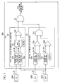
- FIG. 1 is a block diagram of an SRS 50 according to a first embodiment.
- the SRS 50 includes a main collision determination algorithm 51, a safing determination algorithm 52, and a first AND operation 53 (first logical AND operation).
- the main collision determination algorithm 51 performs main collision determination using acceleration data G_R3 acquired from an SIS 20R3 at the last stage among a plurality of satellite sensors (namely SISs 20R1, 20R2, and 20R3) provided on one side surface (in the present embodiment, the right side surface).
- the main collision determination algorithm 51 includes a first main operation 5 1 a (third operation) and a main comparison 51 b (third comparison).
- the first main operation 51a calculates a first velocity variation ⁇ V_M1 (third operation value) for main collision determination by integrating the acceleration data G_R3 acquired from the SIS 20R3 over a predetermined period.
- the main comparison 51b compares the magnitudes of the first velocity variation ⁇ V_M1 1 calculated by the first main operation 5 1 a and a main collision determination threshold TH_Main (third threshold) and obtains the result of the comparison as the result of the main collision determination.
- TH_Main third threshold
- the main comparison 51 b sets the result of the main collision determination to ON ("1").
- the safing determination algorithm 52 performs a safing determination using acceleration data G_L3 acquired from an SIS 20L3 at the last stage among a plurality of satellite sensors (namely, SISs 20L1, 20L2, and 20L3) provided on the other side surface (namely, the left side surface) in addition to the acceleration data G_R2 acquired from the satellite sensor (namely, the SIS 20R2) at the stage preceding the SIS 20R3.
- the safing determination algorithm 52 includes a first SF operation 52a (first operation), a first SF comparison 52b (first comparison), a second SF operation 52c (second operation), a second SF comparison 52d (second comparison), and a second AND operation 52e (second logical AND operation).
- the first SF operation 52a calculates a first velocity variation ⁇ V_SF1 1 (first operation value) for safing determination by integrating the acceleration data G_R2 acquired from the SIS 20R2 over a predetermined period.
- the first SF comparison 52b compares the magnitudes of the first velocity variation AV_SF1 calculated by the first SF operation 52a and a first safing determination threshold TH_SF1 (first threshold).
- TH_SF1 first threshold
- the first SF comparison 52b sets the result of the comparison to ON.
- the second SF operation 52c calculates a second velocity variation AV_SF2 (second operation value) for safing determination by integrating the acceleration data G_L3 acquired from the SIS 20L3 over a predetermined period.
- the second SF comparison 52d compares the magnitudes of the second velocity variation AV_SF2 calculated by the second SF operation 52c and a second safing determination threshold TH_SF2 (second threshold).
- TH_SF2 second threshold
- the second SF comparison 52d sets the result of the comparison to ON.
- the second AND operation 52e performs a logical AND operation between the comparison result of the first SF comparison 52b and the comparison result of the second SF comparison 52d to obtain the result of the logical AND operation as the result of the safing determination. That is, when both the comparison result of the first SF comparison 52b and the comparison result of the second SF comparison 52d are ON, the result of the safing determination will be ON.
- FIG. 2 shows the relationship between the first safing determination threshold TH_SF1 and the second safing determination threshold TH_SF2.
- the first safing determination threshold TH_SF1 has a relatively high value
- the second safing determination threshold TH_SF2 for the opposite side is set to a relatively low value.
- the first safing determination threshold TH_SF1 for the opposite side is set to a relatively low value.
- safing determination thresholds TH_SF1 and TH_SF2 in such a manner, it is possible to prevent the occurrence of a situation where the safing determination erroneously result in ON when a minor collision (a collision of a minor enough extent that it is not necessary to activate an occupant protection system) occurs on the same side surface (in this example, the right side surface).
- the first AND operation 53 performs a logical AND operation between the main collision determination result of the main collision determination algorithm 51 and the safing determination result of the safing determination algorithm 52 and obtains the result of the logical AND operation as the final result of the side collision determination. That is, when both the main collision determination result and the safing determination result is ON, the final result of the side collision determination will be ON.
- the SRS 50 activates an occupant protection system (for example, side airbags and curtain airbags) for side collision.
- the SRS 50 of the present embodiment performs a safing determination using the acceleration data G_R2 acquired from the existing satellite sensor, namely the SIS 20R2 provided at the stage preceding the SIS 20R3 at the last stage.
- the acceleration data G_R3 acquired from the SIS 20R3 and the acceleration data G_R2 acquired from the SIS 20R2 can be suppressed as much as possible.
- the SRS 50 of the present invention it is possible to perform a highly accurate safing determination using the acceleration data acquired from an existing satellite sensor without adding an additional satellite sensor (the CSS 30 in FIG 6 ) for safing determination. Moreover, as described above, in the safing determination, the logical AND operation between the respective threshold comparison result is performed using the acceleration data acquired from the SIS 20R2 and the SIS 20L3 on the opposite side. Thus, it is possible to prevent the occurrence of a situation where the safing determination erroneously result is ON, and accordingly, the side collision determination erroneously result is ON, when a minor collision occurs on the right side surface.
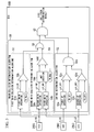
- FIG. 3 is a block diagram of an SRS 50A according to the second embodiment.
- the same constituent elements as the first embodiment ( FIG. 1 ) will be denoted by the same reference numerals, and description thereof will be omitted.
- the SRS 50A of the second embodiment is different in that it includes a main collision determination algorithm 54 of which the collision determination logic is different from that of the main collision determination algorithm 51 described in the first embodiment.
- the main collision determination algorithm 54 performs main collision determination using the acceleration data G_L3 acquired from the SIS 20L3 at the last stage provided on the left side surface, in addition to the acceleration data G_R3 acquired from the SIS 20R3 at the last stage provided on the right side surface.
- the main collision determination algorithm 54 includes a second main operation 54a (fourth operation), a third main operation 54b (fifth operation), a map creation 54c, and a map comparison 54d.
- the map creation 54c and the map comparison 54d correspond to a map determination of the present invention.
- the second main operation 54a calculates a second velocity variation ⁇ V_M2 (fourth operation value) for main collision determination by integrating the acceleration data G_R3 acquired from the SIS 20R3 over a predetermined period.
- the third main operation 54b calculates a third velocity variation ⁇ V_M3 (fifth operation value) for main collision determination by integrating the acceleration data G_L3 acquired from the SIS 20L3 on the opposite side over a predetermined period.
- the map creation 54c plots the intersections of the second velocity variation ⁇ V_M2 calculated by the second main operation 54a and the third velocity variation ⁇ V_M3 calculated by the third main operation 54b on a 2-dimensional map of which the vertical axis is the second velocity variation ⁇ V_M2 and the horizontal axis is the third velocity variation ⁇ V_M3.
- the map comparison 54d determines whether or not an intersection plotted on the 2-dimensional map as above is included in an area (collision area) surrounded by map collision determination thresholds TH_Map and obtains the result of the determination as the result of the main collision determination.
- the map comparison 54d sets the result of the main collision determination to ON.
- the main collision determination algorithm 54 having the above-described collision determination logic, it is possible to prevent the occurrence of a situation where skidding of the vehicle 100 is erroneously determined to be a side collision.
- FIG. 5 is a block diagram of an SRS 50B of the third embodiment.
- the same constituent elements as the first embodiment ( FIG. 1 ) and the second embodiment ( FIG. 3 ) will be denoted by the same reference numerals, and description thereof will be omitted.
- the SRS 50B of the third embodiment is different in that it includes a main collision determination algorithm 55 of which the collision determination logic is different from that of the main collision determination algorithm 51 described in the first embodiment and the main collision determination algorithm 54 described in the second embodiment.
- the main collision determination algorithm 55 includes the main collision determination algorithm 51 described in the first embodiment as a first main collision determination algorithm and the main collision determination algorithm 54 described in the second embodiment as a second main collision determination algorithm.
- the main collision determination algorithm 55 further includes an OR operation 56 (logical OR operation) that performs a logical OR operation between the result of the first main collision determination and the result of the second main collision determination and obtains the result of the logical OR operation as the final result of the main collision determination.
- OR operation 56 logical OR operation
- the main collision determination algorithm 55 of the third embodiment includes both the collision determination logic of the main collision determination algorithm 51 described in the first embodiment (where the main collision determination is performed using the acceleration data G_R3 acquired from the SIS 20R3 at the last stage provided on the right side surface) and the collision determination logic of the main collision determination algorithm 54 described in the second embodiment (where the main collision determination is performed using the acceleration data G_L3 acquired from the SIS 20L3 on the opposite side in addition to the acceleration data G_R3 acquired from the SIS 20R3 at the last stage provided on the right side surface).
- the final main collision determination result will be ON.
- the collision determination logic of the main collision determination algorithm 51 described in the first embodiment is appropriate for high-velocity collision
- the collision determination logic of the main collision determination algorithm 54 described in the second embodiment is appropriate for medium and low-velocity collision. Therefore, by using the SRS 50B of the third embodiment, an even more highly accurate side collision determination can be performed.
- the SRS airbag system shown in FIG. 6 is only an example of a system to which the SRSs 50, 50A, and 50B can be applied, the type of vehicles and the type and number of satellite sensors are not limited to the system of FIG. 6 .
- the vehicle collision determination device according to the present invention can be applied to various system configurations. While preferred embodiments of the invention have been described and illustrated above, it should be understood that these are exemplary of the invention and are not to be considered as limiting. Additions, omissions, substitutions, and other modifications can be made without departing from the scope of the present invention. Accordingly, the invention is not to be considered as being limited by the foregoing description, and is only limited by the scope of the appended claims.
Landscapes
- Engineering & Computer Science (AREA)
- Mechanical Engineering (AREA)
- Air Bags (AREA)
Abstract
Description
- The present invention relates to a vehicle collision determination device, and more particularly, to a vehicle collision determination device that controls the activation of an occupant protection system during a vehicle collision.
- An SRS (Supplemental Restraint System) airbag system is generally known as a system for protecting occupants during a vehicle collision. This SRS airbag system detects the occurrence of a vehicle collision based on acceleration data acquired from satellite sensors provided at each portion of a vehicle and activates an occupant protection system such as an airbag or a seatbelt pretensioner.
-
FIG. 6 shows a configuration example of an SRS airbag system. The satellite sensors come in various types including a front crash sensor (FCS), a side impact sensor (SIS), a central safing sensor (CSS), and the like. The FCSs (seereference numerals vehicle 100 so as to detect an acceleration acting in the longitudinal direction (X-axis direction) of thevehicle 100. The SISs (see reference numerals 20R1, 20R2, 20R3, 20L1, 20L2, and 20L3) are provided on both sides of thevehicle 100 so as to detect an acceleration acting in the lateral direction (Y-axis direction) of thevehicle 100. The CSS (see reference numeral 30) is provided at the center of the rear of thevehicle 100 so as to detect an acceleration acting in the Y-axis direction. - A vehicle collision determination device (ECU: Electronic Control Unit) that controls activation of an occupant protection system based on acceleration data acquired from the satellite sensors provided at each portion of the
vehicle 100 is called an SRS (see reference numeral 40) and is provided at the central portion of thevehicle 100 as a unit independent from the ECU that controls an engine and the like. Moreover, each satellite sensor is a unit in which an acceleration sensor and a communication circuit are integrated. The acceleration sensor outputs an analog acceleration signal corresponding to the result of acceleration detection. The communication circuit converts the analog acceleration signal to acceleration data in accordance with a command from theSRS 40 and sends the acceleration data to theSRS 40. - The SRS 40 includes therein X and Y-axis main G-sensors that detect accelerations acting in the X and Y-axis directions, respectively, and a CPU (Central Processing Unit) that performs collision determination based on the acceleration data acquired from the main G-sensors and the satellite sensors and activates the occupant protection system in accordance with the detection result.
- Regarding the details of the configuration and collision determination method of the conventional SRS airbag system, reference can be made to Japanese Unexamined Patent Application, First Publication No.
2005-263145 No. 2941216 - The SRS 40 performs a safing determination as to a side collision using the acceleration data acquired from the CSS 30 and the internal Y-axis main G-sensor as well as main collision determination as to side collision using the acceleration data acquired from the SISs, and performs final determination as to the side collision based on the AND condition of the main collision determination result and the safing determination result.
- In the related art, the safing determination as to a side collision was performed based on only the acceleration data acquired from the Y-axis main G-sensor. However, in long vehicles with three rows of seats, since the distance from the side collision site to the Y-axis main G-sensor is long, it takes time until the impact is transmitted to the Y-axis main G-sensor. Thus, there was concern about the accuracy of the safing determination (that is, concern about malfunctioning of the occupant protection system). In order to prevent this, the CSS 30 was added at the center of the rear of the vehicle as a satellite sensor for safing determination.
- On the other hand, since the addition of the CSS 30 leads to an increase in the cost of the entire system, there has been a demand recently for the development of a system without the CSS 30 so as to reduce costs. In order to cope with such a demand, it was essential to develop logic capable of performing highly accurate safing determination even without the CSS 30.
- The present invention has been made in view of the situation described above, and it is an object of the present invention to provide a vehicle collision determination device capable of performing highly accurate safing determination without adding an additional satellite sensor for safing determination.
- In order to attain the object, a vehicle collision determination device according to a first solving means of the present invention is a vehicle collision determination device that performs a side collision determination based on acceleration data acquired from first side satellite sensors and second side satellite sensors provided on a first side surface and a second side surface of the vehicle and controls activation of an occupant protection system based on a result of the side collision determination, including: a main collision determination algorithm that performs a main collision determination using a first acceleration data acquired from a first satellite sensor at a last stage among the first side satellite sensors provided on the first side surface; a safing determination algorithm that performs a safing determination using a second acceleration data acquired from a second satellite sensor at a stage preceding the last stage; and a first logical AND operation that performs a logical AND operation between a result of the main collision determination and a result of the safing determination to obtain a result of the logical AND operation as a final result of the side collision determination.
- A vehicle collision determination device according to a second solving means is the vehicle collision determination device according to the first solving means, in which the safing determination algorithm performs the safing determination using a third acceleration data acquired from a third satellite sensor at a last stage among the second side satellite sensors provided on the second side surface in addition to the second acceleration data.
- A vehicle collision determination device according to a third solving means is the vehicle collision determination device according to the second solving means, in which the safing determination algorithm includes: a first operation that calculates a first operation value using the second acceleration data; a first comparison that compares magnitudes of the first operation value and a first threshold value; a second operation that calculates a second operation value using the third acceleration data; a second comparison that compares magnitudes of the second operation value and a second threshold value; and a second logical AND operation that performs a logical AND operation between a result of the comparison by the first comparison and a result of the comparison by the second comparison to obtain a result of the logical AND operation as the result of the safing determination.
- A vehicle collision determination device according to a fourth solving means is the vehicle collision determination device according to any one of the first to third solving means, in which the main collision determination algorithm includes: a third operation that calculates a third operation value using the first acceleration data; and a third comparison that compares magnitudes of the third operation value and a third threshold value and obtains a result of the comparison as the result of the main collision determination.
- A vehicle collision determination device according to a fifth solving means is the vehicle collision determination device according to any one of the first to third solving means, in which the main collision determination algorithm performs the main collision determination using a third acceleration data acquired from a third satellite sensor at a last stage among the second side satellite sensors provided on the second side surface in addition to the first acceleration data.
- A vehicle collision determination device according to a sixth solving means is the vehicle collision determination device according to the fifth solving means, in which the main collision determination algorithm includes: a fourth operation that calculates a fourth operation value using the first acceleration data; a fifth operation that calculates a fifth operation value using the third acceleration data; and a map determination that determines whether or not an intersection of the fourth operation value and the fifth operation value on a 2-dimensional map is included in a collision area set on the 2-dimensional map and obtains a result of the determination as the result of the main collision determination.
- A vehicle collision determination device according to a seventh solving means is the vehicle collision determination device according to any one of the first to third solving means, in which the main collision determination algorithm includes: a first main collision determination algorithm that performs a first main collision determination using the first acceleration data; a second main collision determination algorithm that performs a second main collision determination using the first acceleration data and a third acceleration data acquired from a third satellite sensor at a last stage among the second side satellite sensors provided on the second side surface; and a logical OR operation that performs a logical OR operation between a result of the first main collision determination and a result of the second main collision determination to obtains a result of the logical OR operation as the final result of the main collision determination.
- A vehicle collision determination device according to an eighth solving means is the vehicle collision determination device according to the eighth solving means, in which the first main collision determination algorithm includes: a third operation that calculates a third operation value using the first acceleration data; and a third comparison that compares magnitudes of the third operation value and a third threshold value and obtains a result of the comparison as a result of the first main collision determination, and wherein the second main collision determination algorithm includes: a fourth operation that calculates a fourth operation value using the first acceleration data; a fifth operation that calculates a fifth operation value using the third acceleration data; and a map determination that determines whether or not an intersection of the fourth operation value and the fifth operation value on a 2-dimensional map is included in a collision area set on the 2-dimensional map and obtains a result of the determination as a result of the second main collision determination.
- In the vehicle collision determination device according to the present invention, the safing determination is performed using a satellite sensor at a stage preceding the satellite sensor at the last stage used for the main collision determination among the satellite sensors provided on one side surface. Thus, even when a side collision occurs near the satellite sensor at the last stage, the time for the impact to be transmitted to the satellite sensor at the preceding stage decreases. Therefore, the difference in time between the acceleration data acquired from the satellite sensor at the last stage and the acceleration data acquired from the satellite sensor at the preceding stage can be suppressed as much as possible.
According to the vehicle collision determination device of the present invention, it is possible to perform a highly accurate safing determination using acceleration data acquired from an existing satellite sensor without adding an additional satellite sensor for safing determination. -
-
FIG 1 is a block diagram of a vehicle collision determination device (SRS 50) according to a first embodiment of the present invention. -
FIG. 2 is a diagram showing the relationship between a first safing determination threshold TH_SF1 and a second safing determination threshold TH_SF2 used in asafing determination algorithm 52. -
FIG 3 is a block diagram of a vehicle collision determination device (SRS 50A) according to a second embodiment of the present invention. -
FIG. 4 is a diagram illustrating a map determination function by amap creation 54c and amap comparison 54d in a maincollision determination algorithm 54. -
FIG 5 is a block diagram of a vehicle collision determination device (SRS 50B) according to a third embodiment of the present invention. -
FIG. 6 is a diagram showing a configuration example of an SRS airbag system. - Hereinafter, embodiments of the present invention will be described with reference to the drawings.
In the following description, an SRS used in an SRS airbag system shown inFIG. 6 will be illustrated and described as a vehicle collision determination device according to the present invention. The SRS of the present embodiment will be denoted byreference numeral 50 for differentiation from theSRS 40 shown inFIG. 6 . -
FIG. 1 is a block diagram of anSRS 50 according to a first embodiment. As shown inFIG 1 , theSRS 50 includes a maincollision determination algorithm 51, asafing determination algorithm 52, and a first AND operation 53 (first logical AND operation). - The main
collision determination algorithm 51 performs main collision determination using acceleration data G_R3 acquired from an SIS 20R3 at the last stage among a plurality of satellite sensors (namely SISs 20R1, 20R2, and 20R3) provided on one side surface (in the present embodiment, the right side surface). The maincollision determination algorithm 51 includes a first main operation 5 1 a (third operation) and amain comparison 51 b (third comparison). - The first
main operation 51a calculates a first velocity variation ΔV_M1 (third operation value) for main collision determination by integrating the acceleration data G_R3 acquired from the SIS 20R3 over a predetermined period. Themain comparison 51b compares the magnitudes of the first velocity variation ΔV_M1 1 calculated by the first main operation 5 1 a and a main collision determination threshold TH_Main (third threshold) and obtains the result of the comparison as the result of the main collision determination. Here, when the first velocity variation ΔV_M1 is greater than the main collision determination threshold TH_Main, themain comparison 51 b sets the result of the main collision determination to ON ("1"). - The
safing determination algorithm 52 performs a safing determination using acceleration data G_L3 acquired from an SIS 20L3 at the last stage among a plurality of satellite sensors (namely, SISs 20L1, 20L2, and 20L3) provided on the other side surface (namely, the left side surface) in addition to the acceleration data G_R2 acquired from the satellite sensor (namely, the SIS 20R2) at the stage preceding the SIS 20R3. Thesafing determination algorithm 52 includes afirst SF operation 52a (first operation), a first SFcomparison 52b (first comparison), asecond SF operation 52c (second operation), a second SFcomparison 52d (second comparison), and a second ANDoperation 52e (second logical AND operation). - The
first SF operation 52a calculates a first velocity variation ΔV_SF1 1 (first operation value) for safing determination by integrating the acceleration data G_R2 acquired from the SIS 20R2 over a predetermined period. The first SFcomparison 52b compares the magnitudes of the first velocity variation AV_SF1 calculated by thefirst SF operation 52a and a first safing determination threshold TH_SF1 (first threshold). Here, when the first velocity variation AV_SF1 is greater than the first safing determination threshold TH_SF1, thefirst SF comparison 52b sets the result of the comparison to ON. - The
second SF operation 52c calculates a second velocity variation AV_SF2 (second operation value) for safing determination by integrating the acceleration data G_L3 acquired from the SIS 20L3 over a predetermined period. The second SFcomparison 52d compares the magnitudes of the second velocity variation AV_SF2 calculated by thesecond SF operation 52c and a second safing determination threshold TH_SF2 (second threshold). Here, when the second velocity variation ΔV_SF2 is greater than the second safing determination threshold TH_SF2, thesecond SF comparison 52d sets the result of the comparison to ON. - The second AND
operation 52e performs a logical AND operation between the comparison result of thefirst SF comparison 52b and the comparison result of thesecond SF comparison 52d to obtain the result of the logical AND operation as the result of the safing determination. That is, when both the comparison result of thefirst SF comparison 52b and the comparison result of thesecond SF comparison 52d are ON, the result of the safing determination will be ON. -
FIG. 2 shows the relationship between the first safing determination threshold TH_SF1 and the second safing determination threshold TH_SF2. As shown inFIG. 2 , when the first safing determination threshold TH_SF1 has a relatively high value, the second safing determination threshold TH_SF2 for the opposite side is set to a relatively low value. Similarly, when the second safing determination threshold TH_SF2 has a relatively high value, the first safing determination threshold TH_SF1 for the opposite side is set to a relatively low value. By setting the safing determination thresholds TH_SF1 and TH_SF2 in such a manner, it is possible to prevent the occurrence of a situation where the safing determination erroneously result in ON when a minor collision (a collision of a minor enough extent that it is not necessary to activate an occupant protection system) occurs on the same side surface (in this example, the right side surface). - Returning to
FIG. 1 , the first ANDoperation 53 performs a logical AND operation between the main collision determination result of the maincollision determination algorithm 51 and the safing determination result of thesafing determination algorithm 52 and obtains the result of the logical AND operation as the final result of the side collision determination. That is, when both the main collision determination result and the safing determination result is ON, the final result of the side collision determination will be ON.
When the final side collision determination result is ON as above, theSRS 50 activates an occupant protection system (for example, side airbags and curtain airbags) for side collision. - As described above, the
SRS 50 of the present embodiment performs a safing determination using the acceleration data G_R2 acquired from the existing satellite sensor, namely the SIS 20R2 provided at the stage preceding the SIS 20R3 at the last stage. Thus, even when a side collision occurs near the SIS 20R3 at the last stage, the time for the impact to be transmitted to the SIS 20R2 decreases. Therefore, the difference in time between the acceleration data G_R3 acquired from the SIS 20R3 and the acceleration data G_R2 acquired from the SIS 20R2 can be suppressed as much as possible. - According to the
SRS 50 of the present invention, it is possible to perform a highly accurate safing determination using the acceleration data acquired from an existing satellite sensor without adding an additional satellite sensor (theCSS 30 inFIG 6 ) for safing determination. Moreover, as described above, in the safing determination, the logical AND operation between the respective threshold comparison result is performed using the acceleration data acquired from the SIS 20R2 and the SIS 20L3 on the opposite side. Thus, it is possible to prevent the occurrence of a situation where the safing determination erroneously result is ON, and accordingly, the side collision determination erroneously result is ON, when a minor collision occurs on the right side surface. - Next, a second embodiment of the present invention will be described.
FIG. 3 is a block diagram of anSRS 50A according to the second embodiment. InFIG. 3 , the same constituent elements as the first embodiment (FIG. 1 ) will be denoted by the same reference numerals, and description thereof will be omitted. As shown inFIG. 3 , theSRS 50A of the second embodiment is different in that it includes a maincollision determination algorithm 54 of which the collision determination logic is different from that of the maincollision determination algorithm 51 described in the first embodiment. - The main
collision determination algorithm 54 performs main collision determination using the acceleration data G_L3 acquired from the SIS 20L3 at the last stage provided on the left side surface, in addition to the acceleration data G_R3 acquired from the SIS 20R3 at the last stage provided on the right side surface. The maincollision determination algorithm 54 includes a secondmain operation 54a (fourth operation), a thirdmain operation 54b (fifth operation), amap creation 54c, and amap comparison 54d. Themap creation 54c and themap comparison 54d correspond to a map determination of the present invention. - The second
main operation 54a calculates a second velocity variation ΔV_M2 (fourth operation value) for main collision determination by integrating the acceleration data G_R3 acquired from the SIS 20R3 over a predetermined period. The thirdmain operation 54b calculates a third velocity variation ΔV_M3 (fifth operation value) for main collision determination by integrating the acceleration data G_L3 acquired from the SIS 20L3 on the opposite side over a predetermined period. - As shown in
FIG. 4 , themap creation 54c plots the intersections of the second velocity variation ΔV_M2 calculated by the secondmain operation 54a and the third velocity variation ΔV_M3 calculated by the thirdmain operation 54b on a 2-dimensional map of which the vertical axis is the second velocity variation ΔV_M2 and the horizontal axis is the third velocity variation ΔV_M3. Themap comparison 54d determines whether or not an intersection plotted on the 2-dimensional map as above is included in an area (collision area) surrounded by map collision determination thresholds TH_Map and obtains the result of the determination as the result of the main collision determination. Here, when the intersection of the second velocity variation ΔV_M2 and the third velocity variation ΔV_M3 is included in the collision area, themap comparison 54d sets the result of the main collision determination to ON. - In the
SRS 50A of the second embodiment, by using the maincollision determination algorithm 54 having the above-described collision determination logic, it is possible to prevent the occurrence of a situation where skidding of thevehicle 100 is erroneously determined to be a side collision. - Next, a third embodiment of the present invention will be described.
FIG. 5 is a block diagram of anSRS 50B of the third embodiment. InFIG. 5 , the same constituent elements as the first embodiment (FIG. 1 ) and the second embodiment (FIG. 3 ) will be denoted by the same reference numerals, and description thereof will be omitted. As shown inFIG 5 , theSRS 50B of the third embodiment is different in that it includes a maincollision determination algorithm 55 of which the collision determination logic is different from that of the maincollision determination algorithm 51 described in the first embodiment and the maincollision determination algorithm 54 described in the second embodiment. - More specifically, the main
collision determination algorithm 55 includes the maincollision determination algorithm 51 described in the first embodiment as a first main collision determination algorithm and the maincollision determination algorithm 54 described in the second embodiment as a second main collision determination algorithm. The maincollision determination algorithm 55 further includes an OR operation 56 (logical OR operation) that performs a logical OR operation between the result of the first main collision determination and the result of the second main collision determination and obtains the result of the logical OR operation as the final result of the main collision determination. - That is, the main
collision determination algorithm 55 of the third embodiment includes both the collision determination logic of the maincollision determination algorithm 51 described in the first embodiment (where the main collision determination is performed using the acceleration data G_R3 acquired from the SIS 20R3 at the last stage provided on the right side surface) and the collision determination logic of the maincollision determination algorithm 54 described in the second embodiment (where the main collision determination is performed using the acceleration data G_L3 acquired from the SIS 20L3 on the opposite side in addition to the acceleration data G_R3 acquired from the SIS 20R3 at the last stage provided on the right side surface). When at least one of the determination result is ON, the final main collision determination result will be ON. - The collision determination logic of the main
collision determination algorithm 51 described in the first embodiment is appropriate for high-velocity collision, and the collision determination logic of the maincollision determination algorithm 54 described in the second embodiment is appropriate for medium and low-velocity collision. Therefore, by using theSRS 50B of the third embodiment, an even more highly accurate side collision determination can be performed. - While the first to third embodiments of the present invention have been described above, the present invention is not limited to the embodiments only, and the following modifications are possible.
- (1) The embodiments have been described for a case where focusing on the satellite sensors (SISs 20R1, 20R2, and 20R3) provided on the right side surface, the main collision determination is performed using the acceleration data G_R3 acquired from the SIS 20R3 at the last stage provided on the right side surface, and the safing determination is performed using the acceleration data G_R2 acquired from the SIS 20R2 at the preceding stage. This configuration can cope with a collision on the right side surface but may not be able to cope with a collision on the left side surface. Therefore, in practice, the configurations shown in
FIGS. 1 ,3 , and5 may need to be provided for the satellite sensors (SISs 20L1, 20L2, and 20L3) on the left side surface. -
- (2) The embodiments have been described for a case where three SISs are provided on each side surface of the
vehicle 100. However, the present invention can be applied to a case where two or four SISs, for example, are provided on each side surface. -
- (3) The safing determination logic of the
safing determination algorithm 52 is not limited to that shown inFIGS. 1 ,3 , and5 . The spirit of the present invention is to perform the safing determination using a satellite sensor (the SIS 20R2) disposed on the same side surface close to a satellite sensor (the SIS 20R3) used for the main collision determination. Therefore, the safing determination logic may be changed without departing from the spirit. Moreover, the collision determination logics of the maincollision determination algorithms FIGS. 1 ,3 , and5 . These collision determination logics can be changed in accordance with the accuracy and specifications required for the system. - (4) The SRS airbag system shown in
FIG. 6 is only an example of a system to which theSRSs FIG. 6 . The vehicle collision determination device according to the present invention can be applied to various system configurations.
While preferred embodiments of the invention have been described and illustrated above, it should be understood that these are exemplary of the invention and are not to be considered as limiting. Additions, omissions, substitutions, and other modifications can be made without departing from the scope of the present invention. Accordingly, the invention is not to be considered as being limited by the foregoing description, and is only limited by the scope of the appended claims.
Claims (8)
- A vehicle collision determination device (50, 50A, 50B) that performs a side collision determination based on acceleration data acquired from first side satellite sensors (20R1, 20R2, 20R3) and second side satellite sensors (20L1, 20L2, 20L3) provided on a first side surface and a second side surface of the vehicle (100) and controls activation of an occupant protection system based on a result of the side collision determination, comprising:a main collision determination algorithm (51, 54, 55) that performs a main collision determination using a first acceleration data (G_R3) acquired from a first satellite sensor (20R3) at a last stage among the first side satellite sensors (20R1, 20R2, 20R3) provided on the first side surface;a safing determination algorithm (52) that performs a safing determination using a second acceleration data (G_R2) acquired from a second satellite sensor (20R2) at a stage preceding the last stage; anda first logical AND operation (53) that performs a logical AND operation between a result of the main collision determination and a result of the safing determination to obtain a result of the logical AND operation as a final result of the side collision determination.
- The vehicle collision determination device (50, 50A, 50B) according to claim 1, wherein the safing determination algorithm (52) performs the safing determination using a third acceleration data (G_L3) acquired from a third satellite sensor (20L3) at a last stage among the second side satellite sensors (20L1, 20L2, 20L3) provided on the second side surface in addition to the second acceleration data (G_R2).
- The vehicle collision determination device (50, 50A, 50B) according to claim 2,
wherein the safing determination algorithm (52) includes:a first operation (52a) that calculates a first operation value using the second acceleration data (G_R2);a first comparison (52b) that compares magnitudes of the first operation value and a first threshold value;a second operation (52c) that calculates a second operation value using the third acceleration data (G_L3);a second comparison (52d) that compares magnitudes of the second operation value and a second threshold value; anda second logical AND operation (52e) that performs a logical AND operation between a result of the comparison by the first comparison (52b) and a result of the comparison by the second comparison (52d) to obtain a result of the logical AND operation as the result of the safing determination. - The vehicle collision determination device (50) according to any one of claims 1 to 3,
wherein the main collision determination algorithm (51) includes:a third operation (5 1 a) that calculates a third operation value using the first acceleration data (G_R3); anda third comparison (51b) that compares magnitudes of the third operation value and a third threshold value and obtains a result of the comparison as the result of the main collision determination. - The vehicle collision determination device (50A) according to any one of claims 1 to 3, wherein the main collision determination algorithm (54) performs the main collision determination using a third acceleration data (G_L3) acquired from a third satellite sensor (20L3) at a last stage among the second side satellite sensors (20L1, 20L2, 20L3) provided on the second side surface in addition to the first acceleration data (G_R3).
- The vehicle collision determination device (50A) according to claim 5,
wherein the main collision determination algorithm (54) includes:a fourth operation (54a) that calculates a fourth operation value using the first acceleration data (G_R3);a fifth operation (54b) that calculates a fifth operation value using the third acceleration data (G_L3); anda map determination that determines whether or not an intersection of the fourth operation value and the fifth operation value on a 2-dimensional map is included in a collision area set on the 2-dimensional map and obtains a result of the determination as the result of the main collision determination. - The vehicle collision determination device (50B) according to any one of claims 1 to 3,
wherein the main collision determination algorithm (55) includes:a first main collision determination algorithm (51) that performs a first main collision determination using the first acceleration data (G_R3);a second main collision determination algorithm (54) that performs a second main collision determination using the first acceleration data (G_R3) and a third acceleration data (G_L3) acquired from a third satellite sensor (20L3) at a last stage among the second side satellite sensors (20L1, 20L2, 20L3) provided on the second side surface; anda logical OR operation (56) that performs a logical OR operation between a result of the first main collision determination and a result of the second main collision determination to obtains a result of the logical OR operation as the final result of the main collision determination. - The vehicle collision determination device (50B) according to claim 7,
wherein the first main collision determination algorithm (51) includes:a third operation (51a) that calculates a third operation value using the first acceleration data (G_R3); anda third comparison (51b) that compares magnitudes of the third operation value and a third threshold value and obtains a result of the comparison as a result of the first main collision determination, andwherein the second main collision determination algorithm (54) includes:a fourth operation (54a) that calculates a fourth operation value using the first acceleration data (G_R3);
a fifth operation (54b) that calculates a fifth operation value using the third acceleration data (G_L3); and
a map determination that determines whether or not an intersection of the fourth operation value and the fifth operation value on a 2-dimensional map is included in a collision area set on the 2-dimensional map and obtains a result of the determination as a result of the second main collision determination.
Applications Claiming Priority (1)
| Application Number | Priority Date | Filing Date | Title |
|---|---|---|---|
| JP2009254060A JP5452176B2 (en) | 2009-11-05 | 2009-11-05 | Vehicle collision determination device |
Publications (2)
| Publication Number | Publication Date |
|---|---|
| EP2319733A1 true EP2319733A1 (en) | 2011-05-11 |
| EP2319733B1 EP2319733B1 (en) | 2013-01-23 |
Family
ID=43736085
Family Applications (1)
| Application Number | Title | Priority Date | Filing Date |
|---|---|---|---|
| EP10014223A Not-in-force EP2319733B1 (en) | 2009-11-05 | 2010-11-02 | Vehicle collision determination device |
Country Status (2)
| Country | Link |
|---|---|
| EP (1) | EP2319733B1 (en) |
| JP (1) | JP5452176B2 (en) |
Citations (8)
| Publication number | Priority date | Publication date | Assignee | Title |
|---|---|---|---|---|
| WO1997048582A1 (en) * | 1996-06-21 | 1997-12-24 | Automotive Systems Laboratory, Inc. | Hybrid vehicle crash discrimination system |
| JP2941216B2 (en) | 1995-06-15 | 1999-08-25 | ティーアールダブリュー・インコーポレーテッド | Apparatus and method for controlling actuatable restraint |
| US20010009337A1 (en) * | 2000-01-25 | 2001-07-26 | Yukiyasu Ueno | Activating device of vehicular passenger protection system |
| US20050107933A1 (en) * | 2003-11-17 | 2005-05-19 | Fujitsu Ten Limited | Airbag apparatus |
| JP2005263145A (en) | 2004-03-22 | 2005-09-29 | Denso Corp | Vehicle occupant protection device |
| US20060244245A1 (en) * | 2005-04-27 | 2006-11-02 | Denso Corporation | Side door collision detecting system and occupant protecting system |
| US20070173998A1 (en) * | 2004-10-05 | 2007-07-26 | Takashi Furui | Occupant protection activation device |
| WO2007119285A2 (en) * | 2006-03-22 | 2007-10-25 | Toyota Jidosha Kabushiki Kaisha | Passenger protection device |
Family Cites Families (6)
| Publication number | Priority date | Publication date | Assignee | Title |
|---|---|---|---|---|
| JP2002145005A (en) * | 2000-11-07 | 2002-05-22 | Fujitsu Ten Ltd | Airbag system |
| JP3935740B2 (en) * | 2002-02-21 | 2007-06-27 | 富士通テン株式会社 | Airbag activation device |
| JP4055068B2 (en) * | 2003-02-26 | 2008-03-05 | 株式会社デンソー | Vehicle occupant protection device |
| JP2007008392A (en) * | 2005-07-01 | 2007-01-18 | Denso Corp | Occupant protection system |
| JP4586705B2 (en) * | 2005-10-28 | 2010-11-24 | トヨタ自動車株式会社 | Collision determination system |
| JP2009214726A (en) * | 2008-03-11 | 2009-09-24 | Keihin Corp | Vehicle side collision determining device |
-
2009
- 2009-11-05 JP JP2009254060A patent/JP5452176B2/en not_active Expired - Fee Related
-
2010
- 2010-11-02 EP EP10014223A patent/EP2319733B1/en not_active Not-in-force
Patent Citations (8)
| Publication number | Priority date | Publication date | Assignee | Title |
|---|---|---|---|---|
| JP2941216B2 (en) | 1995-06-15 | 1999-08-25 | ティーアールダブリュー・インコーポレーテッド | Apparatus and method for controlling actuatable restraint |
| WO1997048582A1 (en) * | 1996-06-21 | 1997-12-24 | Automotive Systems Laboratory, Inc. | Hybrid vehicle crash discrimination system |
| US20010009337A1 (en) * | 2000-01-25 | 2001-07-26 | Yukiyasu Ueno | Activating device of vehicular passenger protection system |
| US20050107933A1 (en) * | 2003-11-17 | 2005-05-19 | Fujitsu Ten Limited | Airbag apparatus |
| JP2005263145A (en) | 2004-03-22 | 2005-09-29 | Denso Corp | Vehicle occupant protection device |
| US20070173998A1 (en) * | 2004-10-05 | 2007-07-26 | Takashi Furui | Occupant protection activation device |
| US20060244245A1 (en) * | 2005-04-27 | 2006-11-02 | Denso Corporation | Side door collision detecting system and occupant protecting system |
| WO2007119285A2 (en) * | 2006-03-22 | 2007-10-25 | Toyota Jidosha Kabushiki Kaisha | Passenger protection device |
Also Published As
| Publication number | Publication date |
|---|---|
| EP2319733B1 (en) | 2013-01-23 |
| JP2011098626A (en) | 2011-05-19 |
| JP5452176B2 (en) | 2014-03-26 |
Similar Documents
| Publication | Publication Date | Title |
|---|---|---|
| EP2048039B1 (en) | Post impact safety system with vehicle contact information. | |
| US20120072078A1 (en) | Collision determining apparatus for vehicle | |
| JP6107839B2 (en) | Vehicle occupant protection device | |
| US6981565B2 (en) | Crash detection system including roll-over discrimination | |
| US8244437B2 (en) | Method and system for restraint deployment using lateral kinetic energy | |
| US7422086B2 (en) | Vehicle impact sensor using both accelerometer and pressure sensing for side impact detection | |
| JP2013513506A (en) | Method and controller for determining vehicle collision type | |
| US20070185633A1 (en) | Control module | |
| US9421930B2 (en) | Apparatus and method for protecting vehicle passenger | |
| US10688949B2 (en) | Occupant protection device | |
| US7281599B2 (en) | Passenger protection system | |
| US7568543B2 (en) | Device for controlling restraining means in a vehicle | |
| EP1559616B1 (en) | Vehicle rollover detection using dual-axis acceleration sensing | |
| CN104210451A (en) | Passenger protection system | |
| EP2319733B1 (en) | Vehicle collision determination device | |
| JP2005508792A (en) | Method for determining a critical crash phase for operation of a passive safety device in a vehicle | |
| US12017597B2 (en) | Control device and method for controlling passenger protection device | |
| JP3452014B2 (en) | Activation control device for occupant protection device | |
| JP5041868B2 (en) | Activation system for passenger restraint system | |
| KR102227219B1 (en) | Small overlap collision decision method for airbag deployment | |
| KR20180116867A (en) | System and method for vehicle airbag control | |
| JP2018149987A (en) | Occupant protection system | |
| JP7000087B2 (en) | Vehicle frontal collision detector | |
| JP3452013B2 (en) | Activation control device for occupant protection device | |
| KR20150062535A (en) | Protecting device for passengers of vehicles and control method for the same device |
Legal Events
| Date | Code | Title | Description |
|---|---|---|---|
| PUAI | Public reference made under article 153(3) epc to a published international application that has entered the european phase |
Free format text: ORIGINAL CODE: 0009012 |
|
| AK | Designated contracting states |
Kind code of ref document: A1 Designated state(s): AL AT BE BG CH CY CZ DE DK EE ES FI FR GB GR HR HU IE IS IT LI LT LU LV MC MK MT NL NO PL PT RO RS SE SI SK SM TR |
|
| AX | Request for extension of the european patent |
Extension state: BA ME |
|
| 17P | Request for examination filed |
Effective date: 20111019 |
|
| GRAP | Despatch of communication of intention to grant a patent |
Free format text: ORIGINAL CODE: EPIDOSNIGR1 |
|
| GRAS | Grant fee paid |
Free format text: ORIGINAL CODE: EPIDOSNIGR3 |
|
| GRAA | (expected) grant |
Free format text: ORIGINAL CODE: 0009210 |
|
| AK | Designated contracting states |
Kind code of ref document: B1 Designated state(s): AL AT BE BG CH CY CZ DE DK EE ES FI FR GB GR HR HU IE IS IT LI LT LU LV MC MK MT NL NO PL PT RO RS SE SI SK SM TR |
|
| REG | Reference to a national code |
Ref country code: GB Ref legal event code: FG4D |
|
| REG | Reference to a national code |
Ref country code: CH Ref legal event code: EP |
|
| REG | Reference to a national code |
Ref country code: AT Ref legal event code: REF Ref document number: 594773 Country of ref document: AT Kind code of ref document: T Effective date: 20130215 Ref country code: CH Ref legal event code: EP |
|
| REG | Reference to a national code |
Ref country code: IE Ref legal event code: FG4D |
|
| REG | Reference to a national code |
Ref country code: DE Ref legal event code: R096 Ref document number: 602010004757 Country of ref document: DE Effective date: 20130321 |
|
| REG | Reference to a national code |
Ref country code: AT Ref legal event code: MK05 Ref document number: 594773 Country of ref document: AT Kind code of ref document: T Effective date: 20130123 |
|
| REG | Reference to a national code |
Ref country code: LT Ref legal event code: MG4D |
|
| REG | Reference to a national code |
Ref country code: NL Ref legal event code: VDEP Effective date: 20130123 |
|
| PG25 | Lapsed in a contracting state [announced via postgrant information from national office to epo] |
Ref country code: AT Free format text: LAPSE BECAUSE OF FAILURE TO SUBMIT A TRANSLATION OF THE DESCRIPTION OR TO PAY THE FEE WITHIN THE PRESCRIBED TIME-LIMIT Effective date: 20130123 Ref country code: SE Free format text: LAPSE BECAUSE OF FAILURE TO SUBMIT A TRANSLATION OF THE DESCRIPTION OR TO PAY THE FEE WITHIN THE PRESCRIBED TIME-LIMIT Effective date: 20130123 Ref country code: NO Free format text: LAPSE BECAUSE OF FAILURE TO SUBMIT A TRANSLATION OF THE DESCRIPTION OR TO PAY THE FEE WITHIN THE PRESCRIBED TIME-LIMIT Effective date: 20130423 Ref country code: LT Free format text: LAPSE BECAUSE OF FAILURE TO SUBMIT A TRANSLATION OF THE DESCRIPTION OR TO PAY THE FEE WITHIN THE PRESCRIBED TIME-LIMIT Effective date: 20130123 Ref country code: BE Free format text: LAPSE BECAUSE OF FAILURE TO SUBMIT A TRANSLATION OF THE DESCRIPTION OR TO PAY THE FEE WITHIN THE PRESCRIBED TIME-LIMIT Effective date: 20130123 Ref country code: ES Free format text: LAPSE BECAUSE OF FAILURE TO SUBMIT A TRANSLATION OF THE DESCRIPTION OR TO PAY THE FEE WITHIN THE PRESCRIBED TIME-LIMIT Effective date: 20130504 Ref country code: BG Free format text: LAPSE BECAUSE OF FAILURE TO SUBMIT A TRANSLATION OF THE DESCRIPTION OR TO PAY THE FEE WITHIN THE PRESCRIBED TIME-LIMIT Effective date: 20130423 Ref country code: IS Free format text: LAPSE BECAUSE OF FAILURE TO SUBMIT A TRANSLATION OF THE DESCRIPTION OR TO PAY THE FEE WITHIN THE PRESCRIBED TIME-LIMIT Effective date: 20130523 |
|
| PG25 | Lapsed in a contracting state [announced via postgrant information from national office to epo] |
Ref country code: PL Free format text: LAPSE BECAUSE OF FAILURE TO SUBMIT A TRANSLATION OF THE DESCRIPTION OR TO PAY THE FEE WITHIN THE PRESCRIBED TIME-LIMIT Effective date: 20130123 Ref country code: FI Free format text: LAPSE BECAUSE OF FAILURE TO SUBMIT A TRANSLATION OF THE DESCRIPTION OR TO PAY THE FEE WITHIN THE PRESCRIBED TIME-LIMIT Effective date: 20130123 Ref country code: SI Free format text: LAPSE BECAUSE OF FAILURE TO SUBMIT A TRANSLATION OF THE DESCRIPTION OR TO PAY THE FEE WITHIN THE PRESCRIBED TIME-LIMIT Effective date: 20130123 Ref country code: PT Free format text: LAPSE BECAUSE OF FAILURE TO SUBMIT A TRANSLATION OF THE DESCRIPTION OR TO PAY THE FEE WITHIN THE PRESCRIBED TIME-LIMIT Effective date: 20130523 Ref country code: NL Free format text: LAPSE BECAUSE OF FAILURE TO SUBMIT A TRANSLATION OF THE DESCRIPTION OR TO PAY THE FEE WITHIN THE PRESCRIBED TIME-LIMIT Effective date: 20130123 Ref country code: GR Free format text: LAPSE BECAUSE OF FAILURE TO SUBMIT A TRANSLATION OF THE DESCRIPTION OR TO PAY THE FEE WITHIN THE PRESCRIBED TIME-LIMIT Effective date: 20130424 Ref country code: LV Free format text: LAPSE BECAUSE OF FAILURE TO SUBMIT A TRANSLATION OF THE DESCRIPTION OR TO PAY THE FEE WITHIN THE PRESCRIBED TIME-LIMIT Effective date: 20130123 |
|
| PG25 | Lapsed in a contracting state [announced via postgrant information from national office to epo] |
Ref country code: RS Free format text: LAPSE BECAUSE OF FAILURE TO SUBMIT A TRANSLATION OF THE DESCRIPTION OR TO PAY THE FEE WITHIN THE PRESCRIBED TIME-LIMIT Effective date: 20130123 Ref country code: HR Free format text: LAPSE BECAUSE OF FAILURE TO SUBMIT A TRANSLATION OF THE DESCRIPTION OR TO PAY THE FEE WITHIN THE PRESCRIBED TIME-LIMIT Effective date: 20130123 |
|
| PG25 | Lapsed in a contracting state [announced via postgrant information from national office to epo] |
Ref country code: EE Free format text: LAPSE BECAUSE OF FAILURE TO SUBMIT A TRANSLATION OF THE DESCRIPTION OR TO PAY THE FEE WITHIN THE PRESCRIBED TIME-LIMIT Effective date: 20130123 Ref country code: RO Free format text: LAPSE BECAUSE OF FAILURE TO SUBMIT A TRANSLATION OF THE DESCRIPTION OR TO PAY THE FEE WITHIN THE PRESCRIBED TIME-LIMIT Effective date: 20130123 Ref country code: DK Free format text: LAPSE BECAUSE OF FAILURE TO SUBMIT A TRANSLATION OF THE DESCRIPTION OR TO PAY THE FEE WITHIN THE PRESCRIBED TIME-LIMIT Effective date: 20130123 Ref country code: CZ Free format text: LAPSE BECAUSE OF FAILURE TO SUBMIT A TRANSLATION OF THE DESCRIPTION OR TO PAY THE FEE WITHIN THE PRESCRIBED TIME-LIMIT Effective date: 20130123 Ref country code: SK Free format text: LAPSE BECAUSE OF FAILURE TO SUBMIT A TRANSLATION OF THE DESCRIPTION OR TO PAY THE FEE WITHIN THE PRESCRIBED TIME-LIMIT Effective date: 20130123 |
|
| PG25 | Lapsed in a contracting state [announced via postgrant information from national office to epo] |
Ref country code: CY Free format text: LAPSE BECAUSE OF FAILURE TO SUBMIT A TRANSLATION OF THE DESCRIPTION OR TO PAY THE FEE WITHIN THE PRESCRIBED TIME-LIMIT Effective date: 20130123 |
|
| PLBE | No opposition filed within time limit |
Free format text: ORIGINAL CODE: 0009261 |
|
| STAA | Information on the status of an ep patent application or granted ep patent |
Free format text: STATUS: NO OPPOSITION FILED WITHIN TIME LIMIT |
|
| PG25 | Lapsed in a contracting state [announced via postgrant information from national office to epo] |
Ref country code: IT Free format text: LAPSE BECAUSE OF FAILURE TO SUBMIT A TRANSLATION OF THE DESCRIPTION OR TO PAY THE FEE WITHIN THE PRESCRIBED TIME-LIMIT Effective date: 20130123 |
|
| 26N | No opposition filed |
Effective date: 20131024 |
|
| REG | Reference to a national code |
Ref country code: DE Ref legal event code: R097 Ref document number: 602010004757 Country of ref document: DE Effective date: 20131024 |
|
| PG25 | Lapsed in a contracting state [announced via postgrant information from national office to epo] |
Ref country code: MC Free format text: LAPSE BECAUSE OF FAILURE TO SUBMIT A TRANSLATION OF THE DESCRIPTION OR TO PAY THE FEE WITHIN THE PRESCRIBED TIME-LIMIT Effective date: 20130123 |
|
| REG | Reference to a national code |
Ref country code: FR Ref legal event code: ST Effective date: 20140731 |
|
| REG | Reference to a national code |
Ref country code: IE Ref legal event code: MM4A |
|
| PG25 | Lapsed in a contracting state [announced via postgrant information from national office to epo] |
Ref country code: IE Free format text: LAPSE BECAUSE OF NON-PAYMENT OF DUE FEES Effective date: 20131102 |
|
| PG25 | Lapsed in a contracting state [announced via postgrant information from national office to epo] |
Ref country code: FR Free format text: LAPSE BECAUSE OF NON-PAYMENT OF DUE FEES Effective date: 20131202 |
|
| PG25 | Lapsed in a contracting state [announced via postgrant information from national office to epo] |
Ref country code: SM Free format text: LAPSE BECAUSE OF FAILURE TO SUBMIT A TRANSLATION OF THE DESCRIPTION OR TO PAY THE FEE WITHIN THE PRESCRIBED TIME-LIMIT Effective date: 20130123 |
|
| PG25 | Lapsed in a contracting state [announced via postgrant information from national office to epo] |
Ref country code: TR Free format text: LAPSE BECAUSE OF FAILURE TO SUBMIT A TRANSLATION OF THE DESCRIPTION OR TO PAY THE FEE WITHIN THE PRESCRIBED TIME-LIMIT Effective date: 20130123 |
|
| REG | Reference to a national code |
Ref country code: CH Ref legal event code: PL |
|
| GBPC | Gb: european patent ceased through non-payment of renewal fee |
Effective date: 20141102 |
|
| PG25 | Lapsed in a contracting state [announced via postgrant information from national office to epo] |
Ref country code: CH Free format text: LAPSE BECAUSE OF NON-PAYMENT OF DUE FEES Effective date: 20141130 Ref country code: HU Free format text: LAPSE BECAUSE OF FAILURE TO SUBMIT A TRANSLATION OF THE DESCRIPTION OR TO PAY THE FEE WITHIN THE PRESCRIBED TIME-LIMIT; INVALID AB INITIO Effective date: 20101102 Ref country code: MK Free format text: LAPSE BECAUSE OF FAILURE TO SUBMIT A TRANSLATION OF THE DESCRIPTION OR TO PAY THE FEE WITHIN THE PRESCRIBED TIME-LIMIT Effective date: 20130123 Ref country code: LI Free format text: LAPSE BECAUSE OF NON-PAYMENT OF DUE FEES Effective date: 20141130 Ref country code: LU Free format text: LAPSE BECAUSE OF NON-PAYMENT OF DUE FEES Effective date: 20131102 |
|
| PG25 | Lapsed in a contracting state [announced via postgrant information from national office to epo] |
Ref country code: MT Free format text: LAPSE BECAUSE OF FAILURE TO SUBMIT A TRANSLATION OF THE DESCRIPTION OR TO PAY THE FEE WITHIN THE PRESCRIBED TIME-LIMIT Effective date: 20130123 |
|
| PG25 | Lapsed in a contracting state [announced via postgrant information from national office to epo] |
Ref country code: GB Free format text: LAPSE BECAUSE OF NON-PAYMENT OF DUE FEES Effective date: 20141102 |
|
| PGFP | Annual fee paid to national office [announced via postgrant information from national office to epo] |
Ref country code: DE Payment date: 20151028 Year of fee payment: 6 |
|
| REG | Reference to a national code |
Ref country code: DE Ref legal event code: R119 Ref document number: 602010004757 Country of ref document: DE |
|
| PG25 | Lapsed in a contracting state [announced via postgrant information from national office to epo] |
Ref country code: DE Free format text: LAPSE BECAUSE OF NON-PAYMENT OF DUE FEES Effective date: 20170601 |
|
| PG25 | Lapsed in a contracting state [announced via postgrant information from national office to epo] |
Ref country code: AL Free format text: LAPSE BECAUSE OF FAILURE TO SUBMIT A TRANSLATION OF THE DESCRIPTION OR TO PAY THE FEE WITHIN THE PRESCRIBED TIME-LIMIT Effective date: 20130123 |