EP2319711A1 - Tire and production method for tire - Google Patents
Tire and production method for tire Download PDFInfo
- Publication number
- EP2319711A1 EP2319711A1 EP09800358A EP09800358A EP2319711A1 EP 2319711 A1 EP2319711 A1 EP 2319711A1 EP 09800358 A EP09800358 A EP 09800358A EP 09800358 A EP09800358 A EP 09800358A EP 2319711 A1 EP2319711 A1 EP 2319711A1
- Authority
- EP
- European Patent Office
- Prior art keywords
- groove
- tire
- fence
- circumferential
- circumferential groove
- Prior art date
- Legal status (The legal status is an assumption and is not a legal conclusion. Google has not performed a legal analysis and makes no representation as to the accuracy of the status listed.)
- Granted
Links
Images


Classifications
-
- B—PERFORMING OPERATIONS; TRANSPORTING
- B60—VEHICLES IN GENERAL
- B60C—VEHICLE TYRES; TYRE INFLATION; TYRE CHANGING; CONNECTING VALVES TO INFLATABLE ELASTIC BODIES IN GENERAL; DEVICES OR ARRANGEMENTS RELATED TO TYRES
- B60C11/00—Tyre tread bands; Tread patterns; Anti-skid inserts
- B60C11/03—Tread patterns
- B60C11/0306—Patterns comprising block rows or discontinuous ribs
-
- B—PERFORMING OPERATIONS; TRANSPORTING
- B60—VEHICLES IN GENERAL
- B60C—VEHICLE TYRES; TYRE INFLATION; TYRE CHANGING; CONNECTING VALVES TO INFLATABLE ELASTIC BODIES IN GENERAL; DEVICES OR ARRANGEMENTS RELATED TO TYRES
- B60C11/00—Tyre tread bands; Tread patterns; Anti-skid inserts
- B60C11/03—Tread patterns
- B60C11/0306—Patterns comprising block rows or discontinuous ribs
- B60C11/0309—Patterns comprising block rows or discontinuous ribs further characterised by the groove cross-section
Definitions
- the present invention relates to a tire, in particular, to a tire capable of achieving a high degree of compatibility between improvement of uneven wear resistance of tread rubber and reduction of noise during running of the tire, as well as suppressing crack generation at a groove bottom.
- the present invention also relates to a method of producing such a tire as described above.
- a tire generally has plural circumferential grooves continuously extending along the tire circumferential direction in a tread portion thereof.
- at least some degree of uneven wear which is called “river wear” or “railway wear” occurs along edges of the circumferential grooves and sometimes such uneven wear as described above grows to generate an uneven wear-derived broken portion called “rib punch” in a tread rubber land portion between and along the adjacent circumferential grooves.
- the uneven wear-derived broken portion not only significantly shortens the product life of the tread rubber in terms of wear but also significantly deteriorates driving stability and riding comfort of a vehicle.
- a tire having a linear circumferential groove tends to be the most vulnerable to uneven wear.
- Examples of effective means for improving uneven wear of this type include to provide, as shown in JP 2000-177323 , a pair of grooves, narrow sipes or the like continuously extending in the circumferential direction of a tread surface in tread rubber of a tread portion, to form in the tread portion, by the pair of grooves or narrow sipes, plural stepped land portions separated from the tread rubber land portions and having a step-down surfaces stepped down from the tread surface.
- a surface of a stepped land portion to have slip contact with a road surface within a ground-contact surface of a tread portion of the tire being rotated under a load exerted thereon and thus concentrate a shearing force in the tire circumferential direction opposite to the vehicle travelling direction, i.e. a breaking force, on the stepped land portion, to make the stepped land portion function as a uneven wear sacrifice portion, such that uneven wear like river wear can be prevented or suppressed.
- a linear circumferential groove having a relatively large width has been basically employed as a groove demarcating land portions in a tread in view of resistance to wet skid to be concerned.
- Such a linear circumferential groove causes a problem in that pipe resonance occurs inside the groove, which is a new factor of deteriorating noise problems.
- Pipe resonance is a phenomenon in which, when a groove width of a circumferential groove of a tire makes rapid movements at a leading edge and a trailing edge thereof due to action from an external force during rotation of a tire in contact with the ground, highfrequency vibration is generated at a groove wall (or a land portion wall) and the highfrequency vibration vibrates air inside the circumferential groove at a ground contact surface, i.e. "a pipe", whereby noise deteriorates due to an acoustic resonance effect based thereon.
- Examples of effective means for preventing noise from deteriorating due to pipe resonance described above include provision of groove fences inside the circumferential groove such that the groove fences extend from a groove wall or groove bottom in a direction to block air flow, as shown in JP 11-105511 .
- pipe resonance which causes a noise problem during running of a tire can be remarkably decreased by providing a soft groove fence or blocking structure in the circumferential direction at a predetermined interval therebetween such that a portion of tread rubber extends from a groove wall or a groove bottom in a direction to block air flow to form the groove fence or blocking structure.
- An object of the invention is to provide a tire and a method of producing the tire, in which tire breakage of a groove fence in vulcanization molding and generation of cracks at a groove bottom can be suppressed, noise is relatively low and uneven wear is less likely to occur, by providing a stepped land portion and a groove fence having an optimized shape within a circumferential groove.
- a tire in which noise is relatively low and uneven wear is less likely to occur can be realized by providing at least one of a groove wall surface of the circumferential groove and a side wall surface of the stepped land portion, with a groove fence protruding in the groove widthwise direction of the circumferential groove, in the extending direction of the circumferential groove at a predetermined intervals therebetween; cracks which tend to be generated at the groove bottom can be effectively prevented by designing the shape of the groove fence to have a thin wall portion where a groove bottom side portion thereof has been notched in a section orthogonal to the circumferential groove and setting an angle formed by a notched face of the thin wall portion with respect to the at least one of the wall surfaces provided with the groove fence at 70° or smaller and thus suppressing concentration of stress at a joint portion of the thin wall portion of the groove fence with the groove bottom of the circumferential groove; and breakage of the groove fence in vul
- the present invention is based on the discoveries as described above and the summary thereof is as follows.
- the tire of the aforementioned aspect (1) is characterized in that the groove fence is designed such that the innermost position in the tire radial direction of the thin wall portion thereof provided on at least one of the wall surfaces is located on the outer side in the tire radial direction than the groove bottom portion of the circumferential groove.
- the tire of the aforementioned aspect (1) or (2) is characterized in that the thin wall portion of the groove fence is connected with the groove bottom portion of the circumferential groove with radius of curvature having continuity between the thina wall portion and the groove bottom.
- the tire of any of the aforementioned aspects (1) to (3) is characterized in that the maximum protruding width of the groove fence is in the range of 20 to 80% of the width between the stepped land portion and the groove wall of the circumferential groove in a state where the groove fence is not provided.
- the tire of any of the aforementioned aspects (1) to (4) is characterized in that the groove fences are provided such that at least one groove fence exists within a ground contact region of the tire under a condition in which the prescribed maximum air pressure and the prescribed maximum load capacity are applied to the tire.
- the tire of any of the aforementioned aspects (1) to (5) is characterized in that the groove fence is provided only at the groove wall, located on the outer side in the tire widthwise direction, of the circumferential groove.
- the tire of any of the aforementioned aspects (1) to (6) is characterized in that the circumferential groove is a zigzag groove extending in a zigzag manner along the tire circumferential direction.
- a method of producing a tire in which tire a circumferential groove extending in the tire circumferential direction is provided in a tread portion, the tread portion is demarcated into plural land portions by the circumferential groove, and a groove bottom portion within the circumferential groove, distanced from respective groove walls of the circumferential groove, is provided with a stepped land portion as an uneven wear sacrifice portion having a surface positioned on the inner side in the tire radial direction than tread surfaces of the land portions and designed to have slip contact with a road surface when the tire is rotated under a load exerted thereon, comprises, conducting vulcanization molding such that: a groove fence is provided on at least one of a groove wall surface of the circumferential groove and a side wall surface of the stepped land portion, in the extending direction of the circumferential groove at a predetermined intervals therebetween, such that the groove fence protrudes in the groove widthwise direction of the circumferential groove, wherein the groove fence has a thin wall portion having a shape in which a portion thereof
- a tire and a production method thereof in which tire breakage of a groove fence in vulcanization molding and generation of cracks at a groove bottom can be suppressed, noise is relatively low and uneven wear is less likely to occur.
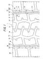
- FIG. 1 is a view showing a tire of the present invention.
- FIG. 1 is a development view of a tread surface.
- FIG. 2 is a sectional view cut along the I-I line in FIG. 1 .
- the present invention is a tire, in which at least one circumferential groove extending along the tire circumferential direction (four circumferential grooves 21 to 24 in FIG.
- tread portion 1 is provided in a tread portion 1, the tread portion 1 is demarcated into plural land portions 31 to 36 by the circumferential grooves 21 to 24, and a stepped land portion 41 having a surface 42 as an uneven wear sacrifice portion of the tire land portions is provided such that the surface is positioned on the inner side in the tire radial direction than tread surfaces of the land portions and has slip contact with a road surface when the tire is rotated with load exerted thereon.
- At least one of a groove wall 71, 72 surface of the circumferential groove 22, 24 and a side wall 43, 44 surface of the stepped land portion 41 is provided with at least one groove fence 51 formed in the extending direction of the circumferential groove 22, 24 at a predetermined intervals therebetween such that the groove fence protrudes in the groove widthwise direction of the circumferential groove 22, 24.
- the groove fence 51 has a thin wall portion 53 having a shape in which a portion thereof on the side of the groove bottom of the circumferential groove 22 has been notched in a section orthogonal to the circumferential groove 22, and an angle formed by a notched face 53 a of the thin wall portion 53 with respect to the at least one of the wall surfaces 71 provided with the groove fence 51 is set at 70° or smaller.
- FIG. 3 is a sectional view cut along the circumferential groove 22, of a tire in which a groove wall, facing the stepped land portion, of the circumferential groove is provided with a groove fence 52 of the conventional shape.
- the inventors of the present invention have assiduously made keen studies regarding a problem that, since a circumferential groove portion 222 facing the stepped land portion 41 has a narrow groove width and the radius of curvature R of the groove bottom 61 is relatively small, provision of the groove fence 52 at the groove wall 71 would result in easy concentration of stress on a joint portion 62 of the innermost position 54 in the tire radial direction of the groove fence 52 and the groove bottom portion of the circumferential groove portion 222, which may cause cracks in the joint portion 62; therefore the groove fence 52 actually cannot be provided and thus pipe resonance occurring within the circumferential groove portion 222 facing the stepped land portion 41 cannot be suppressed.
- the inventors have discovered that, as shown in FIG. 2 , by designing the shape of the groove fence 51 so as to include the thin wall portion 53 having a shape in which a portion thereof on the side of the groove bottom of the circumferential groove 222 in a section orthogonal to the circumferential groove 22 has been notched, concentration of stress on joint portion of the innermost position 62 in the tire radial direction of the thin wall portion 53 of the groove fence 51 and the groove bottom 61 of the circumferential groove portion 22 can be suppressed, whereby the groove fence 51 can be provided in the circumferential groove portion 222 facing the stepped land portion 41 without causing cracks to be generated at the groove bottom 61.
- Provision of the thin wall portion 53 causes a superior effect in terms of suppressing generation of cracks at the groove bottom 61.
- the groove fence 51 having the thin wall portion 53 is produced by vulcanization molding, there is a concern that, when a mold for use in molding is released from a tire, the mold is engaged with the notched face 53a of the thin wall portion 53 and the groove fence is broken as a result of stress exerted thereon in the tire radial direction for releasing the mold from the tire.
- the inventors keenly made further studies regarding optimization of the shape of the thin wall portion 53 and has discovered that, by setting an angle formed by the notched face 53a with respect to the at least one of the wall surfaces 71 provided with the groove fence 51 at 70° or smaller, preferably 60° or smaller, it is possible to offset the mold in the tire axial direction and/or deform the stepped land portion when the mold is lifted up, whereby stress exerted on the groove fence 51 is decreased and breakage of the groove fence 51 in vulcanization molding can be effectively suppressed.
- the thin wall portion 53 represents a groove bottom side portion of the groove fence 51, which groove bottom side portion has a shape in which a portion thereof has been notched in the direction of the groove wall 71.
- the shape of the notched face 53a of the thin wall portion 53 There is no specific restriction on the shape of the notched face 53a of the thin wall portion 53.
- the thin wall portions 53 of various shapes may be used.
- the thin wall portion 53 of the groove fence is preferably connected with the groove bottom portion 61 of the circumferential groove 222 in which the thin wall portion is provided, with radius of curvature having continuity between the thin wall portion and the groove bottom portion.
- the smaller radius of curvature at the groove bottom portion 61 results in the larger stress exerted on the groove bottom, which may cause cracks therein. Stress exerted on the groove bottom can thus be effectively decreased by connecting the thin wall portion with the groove bottom 61 of the circumferential groove portion 222, within the circumferential groove portion 222, with a radius of curvature having continuity between the thin wall portion and the groove bottom 61.
- an angle formed by the notched face 53a of the thin wall portion 53 with respect to the at least one of the wall surfaces 71 provided with the groove fence 51 literally represents the angle ⁇ formed by the notched face 53a with respect to the circumferential groove. Examples thereof include ⁇ 1 formed by the notched face 53a of the thin wall portion 53 with respect to the groove wall 71 of the circumferential groove 22 as shown in FIG. 2 and ⁇ 2 formed by the notched face 53a of the thin wall portion 53 with respect to the side wall 43 of the stepped land portion 41 as shown in FIG. 4(d) .
- the angle ⁇ represents ⁇ 3 formed by the notched face 53a of the thin wall portion 53 with respect to the tangent 61X of the groove bottom portion 61 at the innermost position 62 in the tire radial direction of the thin wall portion 53. Further, in a case where the notched face 53a is curved as shown in FIG.
- the angle ⁇ represents ⁇ 4 formed by the tangent 53X of the notched face 53a with respect to the tangent 61X of the groove bottom 61 at the innermost position 62 in the tire radial direction of the thin wall portion 53.
- the innermost position 62 in the tire radial direction of the thin wall portion 53 provided on at least one of the wall surfaces 71 is preferably located on the outer side in the tire radial direction than the groove bottom 61 portion of the circumferential groove 222.
- the groove bottom portion 61 represents a portion ranging from the deepest portion of the groove bottom toward the side wall 71 to the position where the radius of curvature reaches ⁇ .
- Breakage of the groove fence 51 occurs due to repeated concentration of stress at the groove bottom portion, which concentration of stress is caused by repetition of a ground contact state and a non-contact state of the tire with a road surface in running of the tire. Therefore, an effect of suppressing breakage of a groove fence can be effectively obtained by locating the innermost position 62 in the tire radial direction of the thin wall portion 53 so as to avoid the groove bottom portion 61.
- the maximum protruding width T of the groove fence 51 preferably blocks 20 to 80% of the width W measured between the stepped land portion 41 and the groove wall 71 of the circumferential groove 22 in a state where the groove fence is not provided. In a case where the maximum protruding width T of the groove fence 51 blocks less than 20% of the aforementioned measured width W, sound passes through the clearance and thus an effect of decreasing pipe resonance is insufficient. In a case where the maximum protruding width T of the groove fence 51 exceeds 80% of the measured width W, when a diagonal force such as a side force is exerted on the tire, the groove fence 51 collides with the facing stepped land portion and causes, due to deformation thereof, cracks at the groove bottom 61.
- the thickness in the tire circumferential direction of the groove fence 51 is preferably in the range of 0.5 to 3.0 mm. In a case where the thickness in the tire circumferential direction of the groove fence 51 is less than 0.5 mm, an effect of decreasing pipe resonance by blocking the groove is less likely to be obtained. In a case the thickness in the tire circumferential direction of the groove fence 51 exceeds 3.0 mm, drainage property in a tread surface deteriorates.
- the groove fence is preferably provided such that at least one groove fence exists within a ground contact region under a condition in which the prescribed maximum air pressure and the prescribed maximum load capacity are applied to the tire. Since the groove fence portion is provided such that at least one groove fence portion exists within a ground contact region in running of the tire, the tire can be constantly brought into a state in which the functions of the groove fence are being demonstrated during running of the tire, whereby pipe resonance can be continually suppressed.
- the prescribed maximum air pressure" and “the prescribed maximum load capacity” are “the maximum air pressure” and "the maximum load capacity” prescribed in JATMA YEAR BOOK standardized by JATMA (Japan Automobile Tire Manufacturers Association).
- the groove fence 51 is preferably provided, as shown in FIG. 1(a), only at a groove wall located on the outer side in the tire widthwise direction of the circumferential groove portions 222, 242. Since the groove width of the circumferential groove 222, 242 is narrow and the radius of curvature R of the groove bottom 61 is small, as compared with those of the grooves 21, 23 in the tire center portion, provision of the conventional groove fences in the circumferential groove portions 222, 242 would result in generation of cracks at the groove bottom.
- circumferential grooves 21 to 24 are preferably zigzag grooves extending in a zigzag manner along the tire circumferential direction. Due to this structure, the extension length of the circumferential groove can be changed and thus the frequency of pipe resonance can be varied.
- the groove fence 51 is provided on at least one of the groove wall 71, 72 surface of the circumferential groove 22, 24 and the side wall 43, 44 surface of the stepped land portion 41.
- the groove fence of the present invention can be provided at a groove wall 71 of the circumferential groove 22, 24 in which the stepped land portion 41 is not provided. In this case, there can be obtained a tire in which breakage of groove fence in vulcanization molding can be suppressed, cracks are prevented from being generated at the groove bottom of the circumferential grooves 22, 24, and noise is relatively low.
- the method of producing a tire of the present invention is a method of producing a tire, in which tire a circumferential groove extending in the tire circumferential direction is provided in a tread portion, the tread portion is demarcated into plural land portions by the circumferential groove, and a groove bottom portion within the circumferential groove, distanced from respective groove walls of the circumferential groove, is provided with a stepped land portion as an uneven wear sacrifice portion having a surface positioned on the inner side in the tire radial direction than tread surfaces of the land portions and designed to have slip contact with a road surface when the tire is rotated under a load exerted thereon.
- the method of producing a tire of the present invention includes a vulcanization molding step in which a groove fence is provided on at least one of a groove wall surface of the circumferential groove and a side wall surface of the stepped land portion, in the extending direction of the circumferential groove at a predetermined intervals therebetween, such that the groove fence protrudes in the groove widthwise direction of the circumferential groove, wherein the groove fence has a thin wall portion having a shape in which a portion thereof on the side of the groove bottom of the circumferential groove has been notched in a section orthogonal to the circumferential groove, and an angle formed by a notched face of the thin wall portion with respect to the at least one of the wall surfaces provided with the groove fence is set at 70° or smaller.
- the method of the present invention is effective in that, by optimizing the shape of the thin wall portion, a tire can be released from a mold after vulcanization molding without
- Example 1 there was used as a sample a 15° taper radial ply tire for a truck or a bus (tire size: 11R22.2 16PR, rim size: 8.25), in which: a stepped land portion is provided in the circumferential groove; the groove wall positioned on the outer side in the tire widthwise direction of the circumferential groove portion (depth: 16.7 mm, width: 5 mm, radius of curvature: 2 mm) facing the stepped land portion is provided with groove fences which are formed along the tire circumferential direction at intervals of 250 mm therebetween such that each groove fence has a shape as shown in FIG.
- the tire 2 includes a thin wall portion having depth: 2 mm, the maximum protruding width T: 3 mm and the length H in the tire radial direction: 13 mm and that an angle formed by a notched face of the thin wall portion with respect to the at least one of the wall surfaces provided with the groove fence is set at 60°; and the tire is inflated at an air pressure of 800 kPa.
- Example 2 there was used as a sample a 15° taper radial ply tire for a truck or a bus (tire size: 11R22.2 16PR, rim size: 8.25), in which: a stepped land portion is provided in the circumferential groove; the groove wall positioned on the outer side in the tire widthwise direction of the circumferential groove portion (depth: 16.7 mm, width: 5 mm, radius of curvature: 2 mm) facing the stepped land portion is provided with thirty groove fences formed along the tire circumferential direction at intervals of 250 mm therebetween such that each groove fence has a shape as shown in FIG.
- the tire 2 includes a thin wall portion having depth: 2 mm, the maximum protruding width T: 3 mm and the length H in the tire radial direction: 13 mm; and the tire is inflated at an air pressure of 800 kPa.
- the angle formed by a notched face of the thin wall portion with respect to the groove wall provided with the groove fence is 30°, 50°, 60°, 70°, 80° and 90°, respectively.
- Example 3 respective sample tires were prepared in a manner similar to that of Example 2, except that the groove fences are provided at a side wall of the stepped land portion (not the circumferential groove) positioned on the outer side in the tire widthwise direction.
- Comparative Example 1 there was used as a sample a tire which had been prepared in a manner similar to that of Example 1, except that the circumferential groove facing the stepped land portion lacked the groove fence.
- Comparative Example 2 there was used as a sample a tire which had been prepared in a manner similar to that of Example 1, except that the circumferential groove facing the stepped land portion was provided with groove fences having a shape as shown in FIG. 3 and dimensions of thickness: 2 mm, the maximum protruding width T: 2.5 mm and the length H in the tire radial direction: 15 mm.
- Example 1 and Comparative Example 2 which are provided with groove fences, can decrease noise by 1 to 3 %, as compared with the tire of Comparative Example 1 in which no groove fence is provided in the circumferential groove facing the stepped land portion. Further, it is confirmed that the tire of Example 1, where the shape of the groove fence is optimized, and the tire of Comparative Example 1 having no groove fences provided therein exhibit no generation of cracks at the groove bottom, while the tire of Comparative Example 2, in which the shape of the groove fence is not optimized, exhibits cracks at the groove bottom in a case where the test speed is 60 km/h or larger.
- Example 3 exhibits better results than Example 2, it is confirmed that provision of groove fences on the side of the stepped land portion reduces breakage of groove fences better than provision of groove fences on the side of the circumferential groove.
- the present invention it is possible to provide a tire and a method of producing the tire, in which tire breakage of a groove fence in vulcanization molding can be suppressed, cracks are less likely to happen at a groove bottom, noise is relatively low, and uneven wear is less likely to occur.
Landscapes
- Engineering & Computer Science (AREA)
- Mechanical Engineering (AREA)
- Tires In General (AREA)
- Tyre Moulding (AREA)
Abstract
Description
- The present invention relates to a tire, in particular, to a tire capable of achieving a high degree of compatibility between improvement of uneven wear resistance of tread rubber and reduction of noise during running of the tire, as well as suppressing crack generation at a groove bottom. The present invention also relates to a method of producing such a tire as described above.
- A tire generally has plural circumferential grooves continuously extending along the tire circumferential direction in a tread portion thereof. In a tire having circumferential grooves of this type in a tread portion, at least some degree of uneven wear which is called "river wear" or "railway wear" occurs along edges of the circumferential grooves and sometimes such uneven wear as described above grows to generate an uneven wear-derived broken portion called "rib punch" in a tread rubber land portion between and along the adjacent circumferential grooves. The uneven wear-derived broken portion not only significantly shortens the product life of the tread rubber in terms of wear but also significantly deteriorates driving stability and riding comfort of a vehicle. In this regard, it is well known that a tire having a linear circumferential groove tends to be the most vulnerable to uneven wear.
- Examples of effective means for improving uneven wear of this type include to provide, as shown in
JP 2000-177323 - On the other hand, due to increase in opportunity to run at a relatively high speed as a result of remarkable developments of superhighway networks, a linear circumferential groove having a relatively large width has been basically employed as a groove demarcating land portions in a tread in view of resistance to wet skid to be concerned. Such a linear circumferential groove causes a problem in that pipe resonance occurs inside the groove, which is a new factor of deteriorating noise problems. Pipe resonance is a phenomenon in which, when a groove width of a circumferential groove of a tire makes rapid movements at a leading edge and a trailing edge thereof due to action from an external force during rotation of a tire in contact with the ground, highfrequency vibration is generated at a groove wall (or a land portion wall) and the highfrequency vibration vibrates air inside the circumferential groove at a ground contact surface, i.e. "a pipe", whereby noise deteriorates due to an acoustic resonance effect based thereon.
- Examples of effective means for preventing noise from deteriorating due to pipe resonance described above include provision of groove fences inside the circumferential groove such that the groove fences extend from a groove wall or groove bottom in a direction to block air flow, as shown in
JP 11-105511 - In the case of the tire as disclosed in
JP 2000-177323 JP 11-105511 JP 2000-177323 JP 2000-177323 - An object of the invention is to provide a tire and a method of producing the tire, in which tire breakage of a groove fence in vulcanization molding and generation of cracks at a groove bottom can be suppressed, noise is relatively low and uneven wear is less likely to occur, by providing a stepped land portion and a groove fence having an optimized shape within a circumferential groove.
- The inventors of the present invention, as a result of a keen study to solve the problems described above, have discovered that: a tire in which noise is relatively low and uneven wear is less likely to occur can be realized by providing at least one of a groove wall surface of the circumferential groove and a side wall surface of the stepped land portion, with a groove fence protruding in the groove widthwise direction of the circumferential groove, in the extending direction of the circumferential groove at a predetermined intervals therebetween; cracks which tend to be generated at the groove bottom can be effectively prevented by designing the shape of the groove fence to have a thin wall portion where a groove bottom side portion thereof has been notched in a section orthogonal to the circumferential groove and setting an angle formed by a notched face of the thin wall portion with respect to the at least one of the wall surfaces provided with the groove fence at 70° or smaller and thus suppressing concentration of stress at a joint portion of the thin wall portion of the groove fence with the groove bottom of the circumferential groove; and breakage of the groove fence in vulcanizaition molding can be suppressed by limiting the angle formed by the notched face of the thin wall portion with respect to the wall surface.
- The present invention is based on the discoveries as described above and the summary thereof is as follows.
- (1) A tire, in which a circumferential groove extending in the tire circumferential direction is provided in a tread portion, the tread portion is demarcated into plural land portions by the circumferential groove, and a groove bottom portion within the circumferential groove, distanced from respective groove walls of the circumferential groove, is provided with a stepped land portion as an uneven wear sacrifice portion having a surface positioned on the inner side in the tire radial direction than tread surfaces of the land portions and designed to have slip contact with a road surface when the tire is rotated under a load exerted thereon, comprises:
- a groove fence provided on at least one of a groove wall surface of the circumferential groove and a side wall surface of the stepped land portion, in the extending direction of the circumferential groove at a predetermined intervals therebetween, such that the groove fence protrudes in the groove widthwise direction of the circumferential groove,
- wherein the groove fence has a thin wall portion having a shape in which a portion thereof on the side of the groove bottom of the circumferential groove has been notched in a section orthogonal to the circumferential groove, and an angle formed by a notched face of the thin wall portion with respect to the at least one of the wall surfaces provided with the groove fence is set at 70° or smaller.
- (2) The tire of the aforementioned aspect (1) is characterized in that the groove fence is designed such that the innermost position in the tire radial direction of the thin wall portion thereof provided on at least one of the wall surfaces is located on the outer side in the tire radial direction than the groove bottom portion of the circumferential groove.
- (3) The tire of the aforementioned aspect (1) or (2) is characterized in that the thin wall portion of the groove fence is connected with the groove bottom portion of the circumferential groove with radius of curvature having continuity between the thina wall portion and the groove bottom.
- (4) The tire of any of the aforementioned aspects (1) to (3) is characterized in that the maximum protruding width of the groove fence is in the range of 20 to 80% of the width between the stepped land portion and the groove wall of the circumferential groove in a state where the groove fence is not provided.
- (5) The tire of any of the aforementioned aspects (1) to (4) is characterized in that the groove fences are provided such that at least one groove fence exists within a ground contact region of the tire under a condition in which the prescribed maximum air pressure and the prescribed maximum load capacity are applied to the tire.
- (6) The tire of any of the aforementioned aspects (1) to (5) is characterized in that the groove fence is provided only at the groove wall, located on the outer side in the tire widthwise direction, of the circumferential groove.
- (7) The tire of any of the aforementioned aspects (1) to (6) is characterized in that the circumferential groove is a zigzag groove extending in a zigzag manner along the tire circumferential direction.
- (8) A method of producing a tire, in which tire a circumferential groove extending in the tire circumferential direction is provided in a tread portion, the tread portion is demarcated into plural land portions by the circumferential groove, and a groove bottom portion within the circumferential groove, distanced from respective groove walls of the circumferential groove, is provided with a stepped land portion as an uneven wear sacrifice portion having a surface positioned on the inner side in the tire radial direction than tread surfaces of the land portions and designed to have slip contact with a road surface when the tire is rotated under a load exerted thereon, comprises,
conducting vulcanization molding such that: a groove fence is provided on at least one of a groove wall surface of the circumferential groove and a side wall surface of the stepped land portion, in the extending direction of the circumferential groove at a predetermined intervals therebetween, such that the groove fence protrudes in the groove widthwise direction of the circumferential groove,
wherein the groove fence has a thin wall portion having a shape in which a portion thereof on the side of the groove bottom of the circumferential groove has been notched in a section orthogonal to the circumferential groove, and an angle formed by a notched face of the thin wall portion with respect to the at least one of the wall surfaces provided with the groove fence is set at 70° or smaller. - According to the present invention, there can be provided a tire and a production method thereof, in which tire breakage of a groove fence in vulcanization molding and generation of cracks at a groove bottom can be suppressed, noise is relatively low and uneven wear is less likely to occur.
-
-
FIG. 1 is a tread pattern of a tire according to the present invention. -
FIG. 2 is a sectional view cut along I-I inFig. 1 . -
FIG. 3 is a sectional view in the tire widthwise direction of a circumferential groove facing a stepped land portion in a tire where the groove bottom of the circumferential groove is provided with a groove fence of a conventional shape. -
FIGS. 4(a) to 4(d) are each a sectional view in the tire widthwise direction of a circumferential groove provided with a groove fence having a thin wall portion of varied shape. - A structure of the present invention and reasons for limitation will be described with reference to
FIGS. 1 to 4 hereinafter.
FIG. 1 is a view showing a tire of the present invention.FIG. 1 is a development view of a tread surface.FIG. 2 is a sectional view cut along the I-I line inFIG. 1 . The present invention is a tire, in which at least one circumferential groove extending along the tire circumferential direction (fourcircumferential grooves 21 to 24 inFIG. 1 ) is provided in a tread portion 1, the tread portion 1 is demarcated intoplural land portions 31 to 36 by thecircumferential grooves 21 to 24, and astepped land portion 41 having asurface 42 as an uneven wear sacrifice portion of the tire land portions is provided such that the surface is positioned on the inner side in the tire radial direction than tread surfaces of the land portions and has slip contact with a road surface when the tire is rotated with load exerted thereon. - Further, as shown in
FIG. 1 , at least one of agroove wall circumferential groove side wall stepped land portion 41 is provided with at least onegroove fence 51 formed in the extending direction of thecircumferential groove circumferential groove FIG. 2 , thegroove fence 51 has athin wall portion 53 having a shape in which a portion thereof on the side of the groove bottom of thecircumferential groove 22 has been notched in a section orthogonal to thecircumferential groove 22, and an angle formed by anotched face 53 a of thethin wall portion 53 with respect to the at least one of thewall surfaces 71 provided with thegroove fence 51 is set at 70° or smaller. -
FIG. 3 is a sectional view cut along thecircumferential groove 22, of a tire in which a groove wall, facing the stepped land portion, of the circumferential groove is provided with agroove fence 52 of the conventional shape. The inventors of the present invention have assiduously made keen studies regarding a problem that, since acircumferential groove portion 222 facing thestepped land portion 41 has a narrow groove width and the radius of curvature R of thegroove bottom 61 is relatively small, provision of thegroove fence 52 at thegroove wall 71 would result in easy concentration of stress on ajoint portion 62 of theinnermost position 54 in the tire radial direction of thegroove fence 52 and the groove bottom portion of thecircumferential groove portion 222, which may cause cracks in thejoint portion 62; therefore thegroove fence 52 actually cannot be provided and thus pipe resonance occurring within thecircumferential groove portion 222 facing thestepped land portion 41 cannot be suppressed. As a result, the inventors have discovered that, as shown inFIG. 2 , by designing the shape of thegroove fence 51 so as to include thethin wall portion 53 having a shape in which a portion thereof on the side of the groove bottom of thecircumferential groove 222 in a section orthogonal to thecircumferential groove 22 has been notched, concentration of stress on joint portion of theinnermost position 62 in the tire radial direction of thethin wall portion 53 of thegroove fence 51 and thegroove bottom 61 of thecircumferential groove portion 22 can be suppressed, whereby thegroove fence 51 can be provided in thecircumferential groove portion 222 facing thestepped land portion 41 without causing cracks to be generated at thegroove bottom 61.
Provision of thethin wall portion 53 causes a superior effect in terms of suppressing generation of cracks at thegroove bottom 61. However, in a case where thegroove fence 51 having thethin wall portion 53 is produced by vulcanization molding, there is a concern that, when a mold for use in molding is released from a tire, the mold is engaged with thenotched face 53a of thethin wall portion 53 and the groove fence is broken as a result of stress exerted thereon in the tire radial direction for releasing the mold from the tire. Therefore, the inventors keenly made further studies regarding optimization of the shape of thethin wall portion 53 and has discovered that, by setting an angle formed by thenotched face 53a with respect to the at least one of thewall surfaces 71 provided with thegroove fence 51 at 70° or smaller, preferably 60° or smaller, it is possible to offset the mold in the tire axial direction and/or deform the stepped land portion when the mold is lifted up, whereby stress exerted on thegroove fence 51 is decreased and breakage of thegroove fence 51 in vulcanization molding can be effectively suppressed. - In the present invention, the
thin wall portion 53 represents a groove bottom side portion of thegroove fence 51, which groove bottom side portion has a shape in which a portion thereof has been notched in the direction of thegroove wall 71. There is no specific restriction on the shape of the notchedface 53a of thethin wall portion 53. For example, as shown inFIGS. 4(a) to 4(c) , thethin wall portions 53 of various shapes may be used. Further, thethin wall portion 53 of the groove fence is preferably connected with thegroove bottom portion 61 of thecircumferential groove 222 in which the thin wall portion is provided, with radius of curvature having continuity between the thin wall portion and the groove bottom portion. The smaller radius of curvature at thegroove bottom portion 61 results in the larger stress exerted on the groove bottom, which may cause cracks therein. Stress exerted on the groove bottom can thus be effectively decreased by connecting the thin wall portion with thegroove bottom 61 of thecircumferential groove portion 222, within thecircumferential groove portion 222, with a radius of curvature having continuity between the thin wall portion and thegroove bottom 61. - In the present invention, an angle formed by the
notched face 53a of thethin wall portion 53 with respect to the at least one of thewall surfaces 71 provided with thegroove fence 51 literally represents the angle α formed by thenotched face 53a with respect to the circumferential groove. Examples thereof include α1 formed by the notchedface 53a of thethin wall portion 53 with respect to thegroove wall 71 of thecircumferential groove 22 as shown inFIG. 2 and α2 formed by thenotched face 53a of thethin wall portion 53 with respect to theside wall 43 of thestepped land portion 41 as shown inFIG. 4(d) . Further, when viewed in a section orthogonal to thecircumferential groove 22, in a case where theinnermost position 62 in the tire radial direction of thethin wall portion 53 is positioned at the curvedgroove bottom portion 61 as shown inFIGS. 4(a) and 4(c) , the angle α represents α3 formed by thenotched face 53a of thethin wall portion 53 with respect to the tangent 61X of thegroove bottom portion 61 at theinnermost position 62 in the tire radial direction of thethin wall portion 53. Further, in a case where thenotched face 53a is curved as shown inFIG. 4(b) , the angle α represents α4 formed by the tangent 53X of thenotched face 53a with respect to the tangent 61X of thegroove bottom 61 at theinnermost position 62 in the tire radial direction of thethin wall portion 53. - Further, in the
groove fence 51, as shown inFIG. 2 , theinnermost position 62 in the tire radial direction of thethin wall portion 53 provided on at least one of the wall surfaces 71 (thegroove wall 71 of thecircumferential groove 22 inFIG. 2 ) is preferably located on the outer side in the tire radial direction than thegroove bottom 61 portion of thecircumferential groove 222. In the present invention, thegroove bottom portion 61 represents a portion ranging from the deepest portion of the groove bottom toward theside wall 71 to the position where the radius of curvature reaches ∞. Breakage of thegroove fence 51 occurs due to repeated concentration of stress at the groove bottom portion, which concentration of stress is caused by repetition of a ground contact state and a non-contact state of the tire with a road surface in running of the tire. Therefore, an effect of suppressing breakage of a groove fence can be effectively obtained by locating theinnermost position 62 in the tire radial direction of thethin wall portion 53 so as to avoid thegroove bottom portion 61. Further, if thegroove fence 51 were to be provided at thegroove bottom portion 61, controllably setting an angle α formed by the notchedface 53a of thethin wall portion 53 with respect to the at least one of the wall surfaces 71 provided with thegroove fence 51 at 70° or smaller would be difficult and breakage of thegroove fence 51 in vulcanization molding might not be sufficiently controlled. - Yet further, the maximum protruding width T of the
groove fence 51 preferably blocks 20 to 80% of the width W measured between the steppedland portion 41 and thegroove wall 71 of thecircumferential groove 22 in a state where the groove fence is not provided. In a case where the maximum protruding width T of thegroove fence 51 blocks less than 20% of the aforementioned measured width W, sound passes through the clearance and thus an effect of decreasing pipe resonance is insufficient. In a case where the maximum protruding width T of thegroove fence 51 exceeds 80% of the measured width W, when a diagonal force such as a side force is exerted on the tire, thegroove fence 51 collides with the facing stepped land portion and causes, due to deformation thereof, cracks at thegroove bottom 61. Yet further, the thickness in the tire circumferential direction of thegroove fence 51 is preferably in the range of 0.5 to 3.0 mm. In a case where the thickness in the tire circumferential direction of thegroove fence 51 is less than 0.5 mm, an effect of decreasing pipe resonance by blocking the groove is less likely to be obtained. In a case the thickness in the tire circumferential direction of thegroove fence 51 exceeds 3.0 mm, drainage property in a tread surface deteriorates. - Yet further, the groove fence is preferably provided such that at least one groove fence exists within a ground contact region under a condition in which the prescribed maximum air pressure and the prescribed maximum load capacity are applied to the tire. Since the groove fence portion is provided such that at least one groove fence portion exists within a ground contact region in running of the tire, the tire can be constantly brought into a state in which the functions of the groove fence are being demonstrated during running of the tire, whereby pipe resonance can be continually suppressed. In the present invention, "the prescribed maximum air pressure" and "the prescribed maximum load capacity" are "the maximum air pressure" and "the maximum load capacity" prescribed in JATMA YEAR BOOK standardized by JATMA (Japan Automobile Tire Manufacturers Association).
- The
groove fence 51 is preferably provided, as shown in FIG. 1(a), only at a groove wall located on the outer side in the tire widthwise direction of thecircumferential groove portions circumferential groove grooves circumferential groove portions - Further, the
circumferential grooves 21 to 24 are preferably zigzag grooves extending in a zigzag manner along the tire circumferential direction. Due to this structure, the extension length of the circumferential groove can be changed and thus the frequency of pipe resonance can be varied. - As shown in
FIG. 2 andFIG. 4(d) , thegroove fence 51 is provided on at least one of thegroove wall circumferential groove side wall land portion 41. However, the groove fence of the present invention can be provided at agroove wall 71 of thecircumferential groove land portion 41 is not provided. In this case, there can be obtained a tire in which breakage of groove fence in vulcanization molding can be suppressed, cracks are prevented from being generated at the groove bottom of thecircumferential grooves - Next, a method of producing the tire of the present invention will be described.
The method of producing a tire of the present invention is a method of producing a tire, in which tire a circumferential groove extending in the tire circumferential direction is provided in a tread portion, the tread portion is demarcated into plural land portions by the circumferential groove, and a groove bottom portion within the circumferential groove, distanced from respective groove walls of the circumferential groove, is provided with a stepped land portion as an uneven wear sacrifice portion having a surface positioned on the inner side in the tire radial direction than tread surfaces of the land portions and designed to have slip contact with a road surface when the tire is rotated under a load exerted thereon. Specific production processes thereof are not particularly restricted and the processes similar to those of the conventional tire production method may be employed.
Further, the method of producing a tire of the present invention includes a vulcanization molding step in which a groove fence is provided on at least one of a groove wall surface of the circumferential groove and a side wall surface of the stepped land portion, in the extending direction of the circumferential groove at a predetermined intervals therebetween, such that the groove fence protrudes in the groove widthwise direction of the circumferential groove, wherein the groove fence has a thin wall portion having a shape in which a portion thereof on the side of the groove bottom of the circumferential groove has been notched in a section orthogonal to the circumferential groove, and an angle formed by a notched face of the thin wall portion with respect to the at least one of the wall surfaces provided with the groove fence is set at 70° or smaller. The method of the present invention is effective in that, by optimizing the shape of the thin wall portion, a tire can be released from a mold after vulcanization molding without breaking the groove fence. - The foregoing descriptions show only one example of an embodiment of the present invention and various changes may be made within the scope of accompanying claims.
- Examples of the present invention will be described hereinbelow.
- In Example 1, there was used as a sample a 15° taper radial ply tire for a truck or a bus (tire size: 11R22.2 16PR, rim size: 8.25), in which: a stepped land portion is provided in the circumferential groove; the groove wall positioned on the outer side in the tire widthwise direction of the circumferential groove portion (depth: 16.7 mm, width: 5 mm, radius of curvature: 2 mm) facing the stepped land portion is provided with groove fences which are formed along the tire circumferential direction at intervals of 250 mm therebetween such that each groove fence has a shape as shown in
FIG. 2 and includes a thin wall portion having depth: 2 mm, the maximum protruding width T: 3 mm and the length H in the tire radial direction: 13 mm and that an angle formed by a notched face of the thin wall portion with respect to the at least one of the wall surfaces provided with the groove fence is set at 60°; and the tire is inflated at an air pressure of 800 kPa. - In Example 2, there was used as a sample a 15° taper radial ply tire for a truck or a bus (tire size: 11R22.2 16PR, rim size: 8.25), in which: a stepped land portion is provided in the circumferential groove; the groove wall positioned on the outer side in the tire widthwise direction of the circumferential groove portion (depth: 16.7 mm, width: 5 mm, radius of curvature: 2 mm) facing the stepped land portion is provided with thirty groove fences formed along the tire circumferential direction at intervals of 250 mm therebetween such that each groove fence has a shape as shown in
FIG. 2 and includes a thin wall portion having depth: 2 mm, the maximum protruding width T: 3 mm and the length H in the tire radial direction: 13 mm; and the tire is inflated at an air pressure of 800 kPa.
There were prepared six sample types in which the angle formed by a notched face of the thin wall portion with respect to the groove wall provided with the groove fence is 30°, 50°, 60°, 70°, 80° and 90°, respectively. - In Example 3, respective sample tires were prepared in a manner similar to that of Example 2, except that the groove fences are provided at a side wall of the stepped land portion (not the circumferential groove) positioned on the outer side in the tire widthwise direction.
- In Comparative Example 1, there was used as a sample a tire which had been prepared in a manner similar to that of Example 1, except that the circumferential groove facing the stepped land portion lacked the groove fence.
- In Comparative Example 2, there was used as a sample a tire which had been prepared in a manner similar to that of Example 1, except that the circumferential groove facing the stepped land portion was provided with groove fences having a shape as shown in
FIG. 3 and dimensions of thickness: 2 mm, the maximum protruding width T: 2.5 mm and the length H in the tire radial direction: 15 mm. - For each of the tires of Example 1, Comparative Examples 1 and 2, an indoor noise test and a test by using an indoor tire tester were carried out in a state where the tire was rotated at a test speed of 35 km/h, 65 km/h and 80 km/h, respectively, with load of 3000 kg exerted thereon. The relative values or ratios (%) when the loudness of noise which occurred in Comparative Example 1 was regarded as 100% are shown in Table 1. Further, presence/absence of cracks generated at the groove bottom of the circumferential groove provided with groove fences, observed after running 10,000 km on the indoor tire tester, is shown in Table 1.
-
[Table 1] Groove fence Test speed 35 km/h Test speed 60 km/h Test speed 80 km/h Noise (dB%) Crack generation Noise (dB%) Crack generation Noise (dB%) Crack generation Example 1 Groove fence having thin wall portion 99 No 97 No 98 No Comparative Example 1 None 100 No 100 No 100 No Comparative Example 2 Groove fence of conventional shape 99 No 97 Yes 98 Yes - For each of the sample tires of Example 2 and Example 3, presence/absence of breakage of the groove fence was visually analyzed after the vulcanization molding process in the tire production and the number of the broken groove fence(s) was counted. The counting result for each of the sample tires is shown in Table 2.
-
[Table 2] Sample 1 Sample 2 ample 3 Sample 4 Sample 5 Sample 6 Example 2 Angle 30° 50° 60° 70° 80° 90° Number of broken groove fences None None None 1 4 4 Example 3 Angle 30° 50° 60° 70° 80° 90° Number of broken groove fences None None None None 2 3 - From the results of Table 1, it is confirmed that the tires of Example 1 and Comparative Example 2, which are provided with groove fences, can decrease noise by 1 to 3 %, as compared with the tire of Comparative Example 1 in which no groove fence is provided in the circumferential groove facing the stepped land portion. Further, it is confirmed that the tire of Example 1, where the shape of the groove fence is optimized, and the tire of Comparative Example 1 having no groove fences provided therein exhibit no generation of cracks at the groove bottom, while the tire of Comparative Example 2, in which the shape of the groove fence is not optimized, exhibits cracks at the groove bottom in a case where the test speed is 60 km/h or larger.
Further, from the results of Table 2, it is confirmed that the breakage of the groove fence occurring in vulcanization molding can be significantly suppressed by setting an angle formed by a notched face of the thin wall portion with respect to the at least one of the wall surfaces provided with the groove fence at 70° or smaller. Yet further, since Example 3 exhibits better results than Example 2, it is confirmed that provision of groove fences on the side of the stepped land portion reduces breakage of groove fences better than provision of groove fences on the side of the circumferential groove. - According to the present invention, it is possible to provide a tire and a method of producing the tire, in which tire breakage of a groove fence in vulcanization molding can be suppressed, cracks are less likely to happen at a groove bottom, noise is relatively low, and uneven wear is less likely to occur.
-
- 1
- Tread portion
- 21-24
- Circumferential groove
- 221,222,241,242
- Circumferential groove facing stepped land portion
- 31-36
- Land portion
- 41
- Stepped land portion
- 42
- Surface of stepped land portion
- 51, 52
- Groove fence
- 53
- Thin wall portion
- 54
- Lower portion of groove fence
- 61
- Groove bottom
- 62
- Innermost position in radial direction
- 71
- Groove wall
- 53X, 62X
- Tangent
- R
- Radius of curvature
- W
- Groove width
- T
- Maximum protruding width
- H
- Length in tire radial direction
Claims (8)
- A tire in which a circumferential groove extending in the tire circumferential direction is provided in a tread portion, the tread portion is demarcated into plural land portions by the circumferential groove, and a groove bottom portion within the circumferential groove, distanced from respective groove walls of the circumferential groove, is provided with a stepped land portion as an uneven wear sacrifice portion having a surface positioned on the inner side in the tire radial direction than tread surfaces of the land portions and designed to have slip contact with a road surface when the tire is rotated under a load exerted thereon, comprising:a groove fence provided on at least one of a groove wall surface of the circumferential groove and a side wall surface of the stepped land portion, in the extending direction of the circumferential groove at a predetermined intervals therebetween, such that the groove fence protrudes in the groove widthwise direction of the circumferential groove,wherein the groove fence has a thin wall portion having a shape in which a portion thereof on the side of the groove bottom of the circumferential groove has been notched in a section orthogonal to the circumferential groove, and an angle formed by a notched face of the thin wall portion with respect to the at least one of the wall surfaces provided with the groove fence is set at 70° or smaller.
- The tire of claim 1, wherein the groove fence is designed such that the innermost position in the tire radial direction of the thin wall portion thereof provided on at least one of the wall surfaces is located on the outer side in the tire radial direction than the groove bottom portion of the circumferential groove.
- The tire of claim 1 or 2, wherein the thin wall portion of the groove fence is connected with the groove bottom portion of the circumferential groove with radius of curvature having continuity between the thin wall portion and the groove bottom.
- The tire of any of claims 1 to 3, wherein the maximum protruding width of the groove fence is in the range of 20 to 80% of the width between the stepped land portion and the groove wall of the circumferential groove in a state where the groove fence is not provided.
- The tire of any of claims 1 to 4, wherein the groove fences are provided such that at least one groove fence exists within a ground contact region of the tire under a condition in which the prescribed maximum air pressure and the prescribed maximum load capacity are applied to the tire.
- The tire of any of claims 1 to 5, wherein the groove fence is provided only at the groove wall, located on the outer side in the tire widthwise direction, of the circumferential groove.
- The tire of any of claims 1 to 6, wherein the circumferential groove is a zigzag groove extending in a zigzag manner along the tire circumferential direction.
- A method of producing a tire, in which tire a circumferential groove extending in the tire circumferential direction is provided in a tread portion, the tread portion is demarcated into plural land portions by the circumferential groove, and a groove bottom portion within the circumferential groove, distanced from respective groove walls of the circumferential groove, is provided with a stepped land portion as an uneven wear sacrifice portion having a surface positioned on the inner side in the tire radial direction than tread surfaces of the land portions and designed to have slip contact with a road surface when the tire is rotated under a load exerted thereon, comprising:conducting vulcanization molding such that: a groove fence is provided on at least one of a groove wall surface of the circumferential groove and a side wall surface of the stepped land portion, in the extending direction of the circumferential groove at a predetermined intervals therebetween, such that the groove fence protrudes in the groove widthwise direction of the circumferential groove,wherein the groove fence has a thin wall portion having a shape in which a portion thereof on the side of the groove bottom of the circumferential groove has been notched in a section orthogonal to the circumferential groove, and an angle formed by a notched face of the thin wall portion with respect to the at least one of the wall surfaces provided with the groove fence is set at 70° or smaller.
Applications Claiming Priority (2)
| Application Number | Priority Date | Filing Date | Title |
|---|---|---|---|
| JP2008189056A JP5288922B2 (en) | 2008-07-22 | 2008-07-22 | Tire and tire manufacturing method |
| PCT/JP2009/062897 WO2010010844A1 (en) | 2008-07-22 | 2009-07-16 | Tire and production method for tire |
Publications (3)
| Publication Number | Publication Date |
|---|---|
| EP2319711A1 true EP2319711A1 (en) | 2011-05-11 |
| EP2319711A4 EP2319711A4 (en) | 2014-10-22 |
| EP2319711B1 EP2319711B1 (en) | 2016-08-31 |
Family
ID=41570309
Family Applications (1)
| Application Number | Title | Priority Date | Filing Date |
|---|---|---|---|
| EP09800358.5A Not-in-force EP2319711B1 (en) | 2008-07-22 | 2009-07-16 | Tire and production method for the tire |
Country Status (5)
| Country | Link |
|---|---|
| US (1) | US8931533B2 (en) |
| EP (1) | EP2319711B1 (en) |
| JP (1) | JP5288922B2 (en) |
| CN (1) | CN102143850B (en) |
| WO (1) | WO2010010844A1 (en) |
Cited By (2)
| Publication number | Priority date | Publication date | Assignee | Title |
|---|---|---|---|---|
| FR2995823A1 (en) * | 2012-09-26 | 2014-03-28 | Michelin & Cie | IMPROVED ANTI-NOISE RESONANCE NOISE DEVICE FOR TIRES |
| CN108290451A (en) * | 2015-12-16 | 2018-07-17 | 米其林集团总公司 | Tire with improved abrasion and rolling resistance performance |
Families Citing this family (20)
| Publication number | Priority date | Publication date | Assignee | Title |
|---|---|---|---|---|
| FR2961744B1 (en) * | 2010-06-29 | 2012-08-03 | Michelin Soc Tech | BEARING BAND WITH REDUCED DRIVE NOISE |
| BR112013027657A8 (en) * | 2011-04-28 | 2017-12-26 | Michelin & Cie | PNEUMATIC |
| WO2013001652A1 (en) * | 2011-06-30 | 2013-01-03 | コンパニー ゼネラール デ エタブリッスマン ミシュラン | Pneumatic tire tread |
| WO2013001653A1 (en) * | 2011-06-30 | 2013-01-03 | コンパニー ゼネラール デ エタブリッスマン ミシュラン | Pneumatic tire tread |
| EP2727746B1 (en) * | 2011-06-30 | 2016-08-10 | Compagnie Générale des Etablissements Michelin | Pneumatic tire tread |
| JP5815706B2 (en) * | 2011-06-30 | 2015-11-17 | コンパニー ゼネラール デ エタブリッスマン ミシュラン | Pneumatic tire tread |
| FR2982798B1 (en) * | 2011-11-18 | 2014-01-10 | Michelin Soc Tech | ANTI-NOISE RESONANCE NOISE DEVICE FOR TIRES |
| FR2983114B1 (en) * | 2011-11-25 | 2013-12-20 | Michelin Soc Tech | MOLD COMPRISING A CAVITY FOR MOLDING A CLOSURE DEVICE IN A GROOVE |
| FR2983115B1 (en) * | 2011-11-25 | 2014-06-20 | Michelin Soc Tech | MOLD COMPRISING A CAVITY FOR MOLDING A CLOSURE DEVICE IN A GROOVE |
| FR2990644B1 (en) * | 2012-05-18 | 2014-05-09 | Michelin & Cie | IMPROVED ANTI - NOISE DEVICE FOR TIRE. |
| TWI480182B (en) * | 2012-08-13 | 2015-04-11 | Cheng Shin Rubber Ind Co Ltd | Tire tire groove of the anti-folder structure |
| JP6186260B2 (en) * | 2013-12-06 | 2017-08-23 | 東洋ゴム工業株式会社 | Pneumatic tire |
| JP5974035B2 (en) * | 2014-04-22 | 2016-08-23 | 住友ゴム工業株式会社 | Pneumatic tire manufacturing method |
| DE102014218871A1 (en) * | 2014-09-19 | 2016-03-24 | Continental Reifen Deutschland Gmbh | Vehicle tires |
| JP6449004B2 (en) * | 2014-12-03 | 2019-01-09 | 東洋ゴム工業株式会社 | Pneumatic tire |
| CN104553628A (en) * | 2015-01-28 | 2015-04-29 | 上海轮胎橡胶(集团)股份有限公司轮胎研究所 | Massive pattern |
| JP1535306S (en) * | 2015-04-24 | 2018-10-01 | ||
| FR3045465B1 (en) * | 2015-12-16 | 2017-12-22 | Michelin & Cie | PNEUMATIC HAVING IMPROVED WEAR PROPERTIES |
| DE102015225941A1 (en) * | 2015-12-18 | 2017-06-22 | Continental Reifen Deutschland Gmbh | Vehicle tires |
| CN105667218A (en) * | 2016-03-29 | 2016-06-15 | 江苏通用科技股份有限公司 | Pattern structure for tire tread |
Family Cites Families (16)
| Publication number | Priority date | Publication date | Assignee | Title |
|---|---|---|---|---|
| JP2744612B2 (en) * | 1987-10-20 | 1998-04-28 | 株式会社ブリヂストン | Pneumatic tires for heavy loads that prevent uneven wear |
| JPH03276802A (en) * | 1990-03-05 | 1991-12-09 | Bridgestone Corp | Pneumatic tire |
| JP3103641B2 (en) * | 1991-12-24 | 2000-10-30 | 住友ゴム工業株式会社 | tire |
| DE4403662C2 (en) * | 1994-02-05 | 2001-04-19 | Uniroyal Englebert Gmbh | Vehicle tires |
| JPH08150812A (en) * | 1994-11-30 | 1996-06-11 | Bridgestone Corp | Pneumatic tire |
| JP3815758B2 (en) * | 1997-10-06 | 2006-08-30 | 株式会社ブリヂストン | Heavy duty pneumatic tire |
| JP4054097B2 (en) | 1997-12-25 | 2008-02-27 | 株式会社ブリヂストン | Heavy duty pneumatic radial tire |
| JP4149057B2 (en) | 1998-12-15 | 2008-09-10 | 株式会社ブリヂストン | Pneumatic tire |
| JP2001030715A (en) * | 1999-07-16 | 2001-02-06 | Ohtsu Tire & Rubber Co Ltd :The | Pneumatic tire |
| JP4344501B2 (en) * | 2002-01-18 | 2009-10-14 | 株式会社ブリヂストン | Pneumatic tire |
| JP2005263087A (en) * | 2004-03-19 | 2005-09-29 | Yokohama Rubber Co Ltd:The | Pneumatic tire |
| JP4587284B2 (en) * | 2004-07-26 | 2010-11-24 | 東洋ゴム工業株式会社 | Pneumatic tire |
| JP2006137231A (en) * | 2004-11-10 | 2006-06-01 | Bridgestone Corp | Pneumatic tire |
| JP5011880B2 (en) * | 2005-09-21 | 2012-08-29 | 横浜ゴム株式会社 | Pneumatic tire |
| JP5078372B2 (en) * | 2007-01-22 | 2012-11-21 | 株式会社ブリヂストン | Pneumatic tire |
| WO2009084666A1 (en) | 2007-12-28 | 2009-07-09 | Bridgestone Corporation | Tire |
-
2008
- 2008-07-22 JP JP2008189056A patent/JP5288922B2/en not_active Expired - Fee Related
-
2009
- 2009-07-16 US US13/055,186 patent/US8931533B2/en not_active Expired - Fee Related
- 2009-07-16 EP EP09800358.5A patent/EP2319711B1/en not_active Not-in-force
- 2009-07-16 WO PCT/JP2009/062897 patent/WO2010010844A1/en not_active Ceased
- 2009-07-16 CN CN200980134754.3A patent/CN102143850B/en not_active Expired - Fee Related
Cited By (6)
| Publication number | Priority date | Publication date | Assignee | Title |
|---|---|---|---|---|
| FR2995823A1 (en) * | 2012-09-26 | 2014-03-28 | Michelin & Cie | IMPROVED ANTI-NOISE RESONANCE NOISE DEVICE FOR TIRES |
| WO2014048952A1 (en) * | 2012-09-26 | 2014-04-03 | Compagnie Generale Des Etablissements Michelin | Improved anti-resonance noise device for tire |
| CN104684742A (en) * | 2012-09-26 | 2015-06-03 | 米其林企业总公司 | Improved anti-resonance noise device for tyre |
| CN104684742B (en) * | 2012-09-26 | 2016-12-21 | 米其林企业总公司 | Improved anti-resonance noise device for tires |
| CN108290451A (en) * | 2015-12-16 | 2018-07-17 | 米其林集团总公司 | Tire with improved abrasion and rolling resistance performance |
| CN108290451B (en) * | 2015-12-16 | 2020-10-09 | 米其林集团总公司 | Tires with improved wear and rolling resistance properties |
Also Published As
| Publication number | Publication date |
|---|---|
| US20110126952A1 (en) | 2011-06-02 |
| WO2010010844A1 (en) | 2010-01-28 |
| EP2319711B1 (en) | 2016-08-31 |
| JP5288922B2 (en) | 2013-09-11 |
| US8931533B2 (en) | 2015-01-13 |
| JP2010023728A (en) | 2010-02-04 |
| CN102143850B (en) | 2013-08-14 |
| EP2319711A4 (en) | 2014-10-22 |
| CN102143850A (en) | 2011-08-03 |
Similar Documents
| Publication | Publication Date | Title |
|---|---|---|
| EP2319711B1 (en) | Tire and production method for the tire | |
| EP1892127B1 (en) | Pneumatic tire | |
| EP1864830B1 (en) | Pneumatic tire | |
| EP2390113B1 (en) | Tire | |
| US7980280B2 (en) | Pneumatic tire with tread including ribs having closed sipes | |
| CN103863016B (en) | Pneumatic tire | |
| EP2390115B1 (en) | Tire | |
| EP1759890A1 (en) | Pneumatic tire | |
| JP5078372B2 (en) | Pneumatic tire | |
| JP2004262295A (en) | Heavy duty pneumatic tire for construction vehicle | |
| EP0320215B1 (en) | Radial tyre | |
| EP2340948A1 (en) | Tire | |
| EP2030810A1 (en) | Pneumatic tire | |
| JP4843661B2 (en) | Heavy duty tire | |
| EP3501850A1 (en) | Tire | |
| JP3499346B2 (en) | Pneumatic tire | |
| JP2016203747A (en) | Heavy load tire | |
| CN113453915A (en) | Pneumatic tire | |
| EP2679409B1 (en) | Pneumatic tire | |
| JPS6060010A (en) | Pneumatic tire | |
| US20230398815A1 (en) | Heavy-Duty Vehicle Tire Tread with Improved Robustness | |
| JP2002002222A (en) | Pneumatic tire | |
| JPH09323510A (en) | Pneumatic tire | |
| US20250360757A1 (en) | Tire for a Heavy Duty Vehicle with Improved Grip | |
| EP4267411B1 (en) | A tire tread for long lasting performance |
Legal Events
| Date | Code | Title | Description |
|---|---|---|---|
| PUAI | Public reference made under article 153(3) epc to a published international application that has entered the european phase |
Free format text: ORIGINAL CODE: 0009012 |
|
| 17P | Request for examination filed |
Effective date: 20110209 |
|
| AK | Designated contracting states |
Kind code of ref document: A1 Designated state(s): AT BE BG CH CY CZ DE DK EE ES FI FR GB GR HR HU IE IS IT LI LT LU LV MC MK MT NL NO PL PT RO SE SI SK SM TR |
|
| AX | Request for extension of the european patent |
Extension state: AL BA RS |
|
| DAX | Request for extension of the european patent (deleted) | ||
| A4 | Supplementary search report drawn up and despatched |
Effective date: 20140919 |
|
| RIC1 | Information provided on ipc code assigned before grant |
Ipc: B60C 11/13 20060101ALI20140915BHEP Ipc: B60C 11/04 20060101AFI20140915BHEP |
|
| REG | Reference to a national code |
Ref country code: DE Ref legal event code: R079 Ref document number: 602009040838 Country of ref document: DE Free format text: PREVIOUS MAIN CLASS: B60C0011040000 Ipc: B60C0011030000 |
|
| GRAP | Despatch of communication of intention to grant a patent |
Free format text: ORIGINAL CODE: EPIDOSNIGR1 |
|
| RIC1 | Information provided on ipc code assigned before grant |
Ipc: B60C 11/03 20060101AFI20160126BHEP Ipc: B60C 11/04 20060101ALN20160126BHEP |
|
| RIC1 | Information provided on ipc code assigned before grant |
Ipc: B60C 11/04 20060101ALN20160208BHEP Ipc: B60C 11/03 20060101AFI20160208BHEP |
|
| INTG | Intention to grant announced |
Effective date: 20160226 |
|
| GRAS | Grant fee paid |
Free format text: ORIGINAL CODE: EPIDOSNIGR3 |
|
| GRAA | (expected) grant |
Free format text: ORIGINAL CODE: 0009210 |
|
| AK | Designated contracting states |
Kind code of ref document: B1 Designated state(s): AT BE BG CH CY CZ DE DK EE ES FI FR GB GR HR HU IE IS IT LI LT LU LV MC MK MT NL NO PL PT RO SE SI SK SM TR |
|
| REG | Reference to a national code |
Ref country code: CH Ref legal event code: EP Ref country code: GB Ref legal event code: FG4D |
|
| REG | Reference to a national code |
Ref country code: IE Ref legal event code: FG4D |
|
| REG | Reference to a national code |
Ref country code: DE Ref legal event code: R096 Ref document number: 602009040838 Country of ref document: DE |
|
| REG | Reference to a national code |
Ref country code: AT Ref legal event code: REF Ref document number: 824652 Country of ref document: AT Kind code of ref document: T Effective date: 20161015 |
|
| REG | Reference to a national code |
Ref country code: LT Ref legal event code: MG4D |
|
| REG | Reference to a national code |
Ref country code: NL Ref legal event code: MP Effective date: 20160831 |
|
| REG | Reference to a national code |
Ref country code: AT Ref legal event code: MK05 Ref document number: 824652 Country of ref document: AT Kind code of ref document: T Effective date: 20160831 |
|
| PG25 | Lapsed in a contracting state [announced via postgrant information from national office to epo] |
Ref country code: HR Free format text: LAPSE BECAUSE OF FAILURE TO SUBMIT A TRANSLATION OF THE DESCRIPTION OR TO PAY THE FEE WITHIN THE PRESCRIBED TIME-LIMIT Effective date: 20160831 Ref country code: NO Free format text: LAPSE BECAUSE OF FAILURE TO SUBMIT A TRANSLATION OF THE DESCRIPTION OR TO PAY THE FEE WITHIN THE PRESCRIBED TIME-LIMIT Effective date: 20161130 Ref country code: FI Free format text: LAPSE BECAUSE OF FAILURE TO SUBMIT A TRANSLATION OF THE DESCRIPTION OR TO PAY THE FEE WITHIN THE PRESCRIBED TIME-LIMIT Effective date: 20160831 Ref country code: LT Free format text: LAPSE BECAUSE OF FAILURE TO SUBMIT A TRANSLATION OF THE DESCRIPTION OR TO PAY THE FEE WITHIN THE PRESCRIBED TIME-LIMIT Effective date: 20160831 |
|
| PG25 | Lapsed in a contracting state [announced via postgrant information from national office to epo] |
Ref country code: SE Free format text: LAPSE BECAUSE OF FAILURE TO SUBMIT A TRANSLATION OF THE DESCRIPTION OR TO PAY THE FEE WITHIN THE PRESCRIBED TIME-LIMIT Effective date: 20160831 Ref country code: AT Free format text: LAPSE BECAUSE OF FAILURE TO SUBMIT A TRANSLATION OF THE DESCRIPTION OR TO PAY THE FEE WITHIN THE PRESCRIBED TIME-LIMIT Effective date: 20160831 Ref country code: NL Free format text: LAPSE BECAUSE OF FAILURE TO SUBMIT A TRANSLATION OF THE DESCRIPTION OR TO PAY THE FEE WITHIN THE PRESCRIBED TIME-LIMIT Effective date: 20160831 Ref country code: GR Free format text: LAPSE BECAUSE OF FAILURE TO SUBMIT A TRANSLATION OF THE DESCRIPTION OR TO PAY THE FEE WITHIN THE PRESCRIBED TIME-LIMIT Effective date: 20161201 Ref country code: ES Free format text: LAPSE BECAUSE OF FAILURE TO SUBMIT A TRANSLATION OF THE DESCRIPTION OR TO PAY THE FEE WITHIN THE PRESCRIBED TIME-LIMIT Effective date: 20160831 Ref country code: LV Free format text: LAPSE BECAUSE OF FAILURE TO SUBMIT A TRANSLATION OF THE DESCRIPTION OR TO PAY THE FEE WITHIN THE PRESCRIBED TIME-LIMIT Effective date: 20160831 |
|
| PG25 | Lapsed in a contracting state [announced via postgrant information from national office to epo] |
Ref country code: EE Free format text: LAPSE BECAUSE OF FAILURE TO SUBMIT A TRANSLATION OF THE DESCRIPTION OR TO PAY THE FEE WITHIN THE PRESCRIBED TIME-LIMIT Effective date: 20160831 Ref country code: RO Free format text: LAPSE BECAUSE OF FAILURE TO SUBMIT A TRANSLATION OF THE DESCRIPTION OR TO PAY THE FEE WITHIN THE PRESCRIBED TIME-LIMIT Effective date: 20160831 |
|
| PG25 | Lapsed in a contracting state [announced via postgrant information from national office to epo] |
Ref country code: BG Free format text: LAPSE BECAUSE OF FAILURE TO SUBMIT A TRANSLATION OF THE DESCRIPTION OR TO PAY THE FEE WITHIN THE PRESCRIBED TIME-LIMIT Effective date: 20161130 Ref country code: PL Free format text: LAPSE BECAUSE OF FAILURE TO SUBMIT A TRANSLATION OF THE DESCRIPTION OR TO PAY THE FEE WITHIN THE PRESCRIBED TIME-LIMIT Effective date: 20160831 Ref country code: DK Free format text: LAPSE BECAUSE OF FAILURE TO SUBMIT A TRANSLATION OF THE DESCRIPTION OR TO PAY THE FEE WITHIN THE PRESCRIBED TIME-LIMIT Effective date: 20160831 Ref country code: SM Free format text: LAPSE BECAUSE OF FAILURE TO SUBMIT A TRANSLATION OF THE DESCRIPTION OR TO PAY THE FEE WITHIN THE PRESCRIBED TIME-LIMIT Effective date: 20160831 Ref country code: PT Free format text: LAPSE BECAUSE OF FAILURE TO SUBMIT A TRANSLATION OF THE DESCRIPTION OR TO PAY THE FEE WITHIN THE PRESCRIBED TIME-LIMIT Effective date: 20170102 Ref country code: BE Free format text: LAPSE BECAUSE OF FAILURE TO SUBMIT A TRANSLATION OF THE DESCRIPTION OR TO PAY THE FEE WITHIN THE PRESCRIBED TIME-LIMIT Effective date: 20160831 Ref country code: CZ Free format text: LAPSE BECAUSE OF FAILURE TO SUBMIT A TRANSLATION OF THE DESCRIPTION OR TO PAY THE FEE WITHIN THE PRESCRIBED TIME-LIMIT Effective date: 20160831 Ref country code: SK Free format text: LAPSE BECAUSE OF FAILURE TO SUBMIT A TRANSLATION OF THE DESCRIPTION OR TO PAY THE FEE WITHIN THE PRESCRIBED TIME-LIMIT Effective date: 20160831 |
|
| REG | Reference to a national code |
Ref country code: DE Ref legal event code: R097 Ref document number: 602009040838 Country of ref document: DE |
|
| PLBE | No opposition filed within time limit |
Free format text: ORIGINAL CODE: 0009261 |
|
| STAA | Information on the status of an ep patent application or granted ep patent |
Free format text: STATUS: NO OPPOSITION FILED WITHIN TIME LIMIT |
|
| REG | Reference to a national code |
Ref country code: FR Ref legal event code: PLFP Year of fee payment: 9 |
|
| 26N | No opposition filed |
Effective date: 20170601 |
|
| PG25 | Lapsed in a contracting state [announced via postgrant information from national office to epo] |
Ref country code: SI Free format text: LAPSE BECAUSE OF FAILURE TO SUBMIT A TRANSLATION OF THE DESCRIPTION OR TO PAY THE FEE WITHIN THE PRESCRIBED TIME-LIMIT Effective date: 20160831 |
|
| REG | Reference to a national code |
Ref country code: CH Ref legal event code: PL |
|
| GBPC | Gb: european patent ceased through non-payment of renewal fee |
Effective date: 20170716 |
|
| REG | Reference to a national code |
Ref country code: IE Ref legal event code: MM4A |
|
| PG25 | Lapsed in a contracting state [announced via postgrant information from national office to epo] |
Ref country code: CH Free format text: LAPSE BECAUSE OF NON-PAYMENT OF DUE FEES Effective date: 20170731 Ref country code: IE Free format text: LAPSE BECAUSE OF NON-PAYMENT OF DUE FEES Effective date: 20170716 Ref country code: LI Free format text: LAPSE BECAUSE OF NON-PAYMENT OF DUE FEES Effective date: 20170731 Ref country code: GB Free format text: LAPSE BECAUSE OF NON-PAYMENT OF DUE FEES Effective date: 20170716 |
|
| PG25 | Lapsed in a contracting state [announced via postgrant information from national office to epo] |
Ref country code: LU Free format text: LAPSE BECAUSE OF NON-PAYMENT OF DUE FEES Effective date: 20170716 |
|
| REG | Reference to a national code |
Ref country code: FR Ref legal event code: PLFP Year of fee payment: 10 |
|
| PG25 | Lapsed in a contracting state [announced via postgrant information from national office to epo] |
Ref country code: MT Free format text: LAPSE BECAUSE OF NON-PAYMENT OF DUE FEES Effective date: 20170716 |
|
| PG25 | Lapsed in a contracting state [announced via postgrant information from national office to epo] |
Ref country code: MC Free format text: LAPSE BECAUSE OF FAILURE TO SUBMIT A TRANSLATION OF THE DESCRIPTION OR TO PAY THE FEE WITHIN THE PRESCRIBED TIME-LIMIT Effective date: 20160831 Ref country code: HU Free format text: LAPSE BECAUSE OF FAILURE TO SUBMIT A TRANSLATION OF THE DESCRIPTION OR TO PAY THE FEE WITHIN THE PRESCRIBED TIME-LIMIT; INVALID AB INITIO Effective date: 20090716 |
|
| PG25 | Lapsed in a contracting state [announced via postgrant information from national office to epo] |
Ref country code: CY Free format text: LAPSE BECAUSE OF NON-PAYMENT OF DUE FEES Effective date: 20160831 |
|
| PGFP | Annual fee paid to national office [announced via postgrant information from national office to epo] |
Ref country code: IT Payment date: 20190730 Year of fee payment: 11 |
|
| PG25 | Lapsed in a contracting state [announced via postgrant information from national office to epo] |
Ref country code: MK Free format text: LAPSE BECAUSE OF FAILURE TO SUBMIT A TRANSLATION OF THE DESCRIPTION OR TO PAY THE FEE WITHIN THE PRESCRIBED TIME-LIMIT Effective date: 20160831 |
|
| PG25 | Lapsed in a contracting state [announced via postgrant information from national office to epo] |
Ref country code: TR Free format text: LAPSE BECAUSE OF FAILURE TO SUBMIT A TRANSLATION OF THE DESCRIPTION OR TO PAY THE FEE WITHIN THE PRESCRIBED TIME-LIMIT Effective date: 20160831 |
|
| PG25 | Lapsed in a contracting state [announced via postgrant information from national office to epo] |
Ref country code: IS Free format text: LAPSE BECAUSE OF FAILURE TO SUBMIT A TRANSLATION OF THE DESCRIPTION OR TO PAY THE FEE WITHIN THE PRESCRIBED TIME-LIMIT Effective date: 20161231 |
|
| PGFP | Annual fee paid to national office [announced via postgrant information from national office to epo] |
Ref country code: FR Payment date: 20200723 Year of fee payment: 12 Ref country code: DE Payment date: 20200721 Year of fee payment: 12 |
|
| PG25 | Lapsed in a contracting state [announced via postgrant information from national office to epo] |
Ref country code: IT Free format text: LAPSE BECAUSE OF NON-PAYMENT OF DUE FEES Effective date: 20200716 |
|
| REG | Reference to a national code |
Ref country code: DE Ref legal event code: R119 Ref document number: 602009040838 Country of ref document: DE |
|
| PG25 | Lapsed in a contracting state [announced via postgrant information from national office to epo] |
Ref country code: DE Free format text: LAPSE BECAUSE OF NON-PAYMENT OF DUE FEES Effective date: 20220201 |
|
| PG25 | Lapsed in a contracting state [announced via postgrant information from national office to epo] |
Ref country code: FR Free format text: LAPSE BECAUSE OF NON-PAYMENT OF DUE FEES Effective date: 20210731 |