EP2319610B1 - Filtration assemblies and methods of installing filtration units in filtration assemblies - Google Patents
Filtration assemblies and methods of installing filtration units in filtration assemblies Download PDFInfo
- Publication number
- EP2319610B1 EP2319610B1 EP11152307A EP11152307A EP2319610B1 EP 2319610 B1 EP2319610 B1 EP 2319610B1 EP 11152307 A EP11152307 A EP 11152307A EP 11152307 A EP11152307 A EP 11152307A EP 2319610 B1 EP2319610 B1 EP 2319610B1
- Authority
- EP
- European Patent Office
- Prior art keywords
- filtration
- alignment rod
- fitting
- units
- end pieces
- Prior art date
- Legal status (The legal status is an assumption and is not a legal conclusion. Google has not performed a legal analysis and makes no representation as to the accuracy of the status listed.)
- Active
Links
- 238000001914 filtration Methods 0.000 title claims abstract description 249
- 238000000034 method Methods 0.000 title claims abstract description 19
- 238000000429 assembly Methods 0.000 title abstract description 27
- 230000000712 assembly Effects 0.000 title abstract description 27
- 239000012466 permeate Substances 0.000 claims description 30
- 230000006835 compression Effects 0.000 claims description 15
- 238000007906 compression Methods 0.000 claims description 15
- 239000012530 fluid Substances 0.000 description 27
- 239000012465 retentate Substances 0.000 description 21
- 238000003780 insertion Methods 0.000 description 7
- 230000037431 insertion Effects 0.000 description 7
- 238000009295 crossflow filtration Methods 0.000 description 6
- 238000006073 displacement reaction Methods 0.000 description 5
- 230000007246 mechanism Effects 0.000 description 5
- 230000006870 function Effects 0.000 description 4
- 238000009434 installation Methods 0.000 description 3
- 239000000463 material Substances 0.000 description 3
- 238000000926 separation method Methods 0.000 description 3
- 239000000126 substance Substances 0.000 description 3
- 230000008901 benefit Effects 0.000 description 2
- 230000008878 coupling Effects 0.000 description 2
- 238000010168 coupling process Methods 0.000 description 2
- 238000005859 coupling reaction Methods 0.000 description 2
- 230000000881 depressing effect Effects 0.000 description 2
- 230000000994 depressogenic effect Effects 0.000 description 2
- 239000002184 metal Substances 0.000 description 2
- 229910001220 stainless steel Inorganic materials 0.000 description 2
- 239000010935 stainless steel Substances 0.000 description 2
- 102000004190 Enzymes Human genes 0.000 description 1
- 108090000790 Enzymes Proteins 0.000 description 1
- 230000002457 bidirectional effect Effects 0.000 description 1
- 239000003054 catalyst Substances 0.000 description 1
- 230000005465 channeling Effects 0.000 description 1
- 238000004891 communication Methods 0.000 description 1
- 239000012141 concentrate Substances 0.000 description 1
- 238000010276 construction Methods 0.000 description 1
- 239000000706 filtrate Substances 0.000 description 1
- 125000000524 functional group Chemical group 0.000 description 1
- 230000002209 hydrophobic effect Effects 0.000 description 1
- 239000003456 ion exchange resin Substances 0.000 description 1
- 229920003303 ion-exchange polymer Polymers 0.000 description 1
- 239000003446 ligand Substances 0.000 description 1
- 238000003754 machining Methods 0.000 description 1
- 230000007935 neutral effect Effects 0.000 description 1
- 230000008569 process Effects 0.000 description 1
- 230000000717 retained effect Effects 0.000 description 1
- 238000005070 sampling Methods 0.000 description 1
- 239000002594 sorbent Substances 0.000 description 1
Images


Classifications
-
- B—PERFORMING OPERATIONS; TRANSPORTING
- B01—PHYSICAL OR CHEMICAL PROCESSES OR APPARATUS IN GENERAL
- B01D—SEPARATION
- B01D63/00—Apparatus in general for separation processes using semi-permeable membranes
- B01D63/08—Flat membrane modules
- B01D63/081—Manufacturing thereof
-
- B—PERFORMING OPERATIONS; TRANSPORTING
- B01—PHYSICAL OR CHEMICAL PROCESSES OR APPARATUS IN GENERAL
- B01D—SEPARATION
- B01D63/00—Apparatus in general for separation processes using semi-permeable membranes
- B01D63/08—Flat membrane modules
- B01D63/082—Flat membrane modules comprising a stack of flat membranes
-
- B—PERFORMING OPERATIONS; TRANSPORTING
- B01—PHYSICAL OR CHEMICAL PROCESSES OR APPARATUS IN GENERAL
- B01D—SEPARATION
- B01D65/00—Accessories or auxiliary operations, in general, for separation processes or apparatus using semi-permeable membranes
-
- B—PERFORMING OPERATIONS; TRANSPORTING
- B01—PHYSICAL OR CHEMICAL PROCESSES OR APPARATUS IN GENERAL
- B01D—SEPARATION
- B01D2313/00—Details relating to membrane modules or apparatus
- B01D2313/02—Specific tightening or locking mechanisms
-
- B—PERFORMING OPERATIONS; TRANSPORTING
- B01—PHYSICAL OR CHEMICAL PROCESSES OR APPARATUS IN GENERAL
- B01D—SEPARATION
- B01D2313/00—Details relating to membrane modules or apparatus
- B01D2313/06—External membrane module supporting or fixing means
-
- Y—GENERAL TAGGING OF NEW TECHNOLOGICAL DEVELOPMENTS; GENERAL TAGGING OF CROSS-SECTIONAL TECHNOLOGIES SPANNING OVER SEVERAL SECTIONS OF THE IPC; TECHNICAL SUBJECTS COVERED BY FORMER USPC CROSS-REFERENCE ART COLLECTIONS [XRACs] AND DIGESTS
- Y10—TECHNICAL SUBJECTS COVERED BY FORMER USPC
- Y10T—TECHNICAL SUBJECTS COVERED BY FORMER US CLASSIFICATION
- Y10T29/00—Metal working
- Y10T29/49—Method of mechanical manufacture
- Y10T29/496—Multiperforated metal article making
- Y10T29/49604—Filter
-
- Y—GENERAL TAGGING OF NEW TECHNOLOGICAL DEVELOPMENTS; GENERAL TAGGING OF CROSS-SECTIONAL TECHNOLOGIES SPANNING OVER SEVERAL SECTIONS OF THE IPC; TECHNICAL SUBJECTS COVERED BY FORMER USPC CROSS-REFERENCE ART COLLECTIONS [XRACs] AND DIGESTS
- Y10—TECHNICAL SUBJECTS COVERED BY FORMER USPC
- Y10T—TECHNICAL SUBJECTS COVERED BY FORMER US CLASSIFICATION
- Y10T29/00—Metal working
- Y10T29/49—Method of mechanical manufacture
- Y10T29/49718—Repairing
- Y10T29/49721—Repairing with disassembling
- Y10T29/4973—Replacing of defective part
-
- Y—GENERAL TAGGING OF NEW TECHNOLOGICAL DEVELOPMENTS; GENERAL TAGGING OF CROSS-SECTIONAL TECHNOLOGIES SPANNING OVER SEVERAL SECTIONS OF THE IPC; TECHNICAL SUBJECTS COVERED BY FORMER USPC CROSS-REFERENCE ART COLLECTIONS [XRACs] AND DIGESTS
- Y10—TECHNICAL SUBJECTS COVERED BY FORMER USPC
- Y10T—TECHNICAL SUBJECTS COVERED BY FORMER US CLASSIFICATION
- Y10T29/00—Metal working
- Y10T29/49—Method of mechanical manufacture
- Y10T29/49826—Assembling or joining
Definitions
- the invention relates to filtration assemblies and methods of installing filtration units into filtration assemblies for any and all types of separation processes. More particularly, it relates to filtration assemblies including removably attachable alignment rod arrangements.
- EP 0 322 604 , EP 0535 446 and US 4 849 102 disclose filtration units compressed between end plates by rods having both an alignment and compression function.
- US 3 831 763 discloses filtration units hold in place by alignment rods and being compressed by separate compression rods. However the filtration units cannot be removed by simply loosening the compression rods.
- Filtration assemblies embodying the invention may be arranged for tangential flow filtration or for direct flow or dead-end flow filtration.
- process or feed fluid is directed to a permeable filtration medium. All of the feed fluid then passes through the filtration medium as filtrate or permeate, except any substances in the fluid that are retained by the filtration medium.
- feed fluid is directed tangentially along a permeable filtration medium. A portion of the feed fluid passes through the filtration medium as permeate, and the remaining portion of the feed fluid, the concentrate or retentate, is directed away from the filtration medium.
- Filtration assemblies embodying the invention include at least one filtration unit, and for many embodiments several filtration units, aligned and compressed between first and second end pieces. At least one alignment rod arrangement extends between the end pieces and align the filtration units. An end piece further comprises a fitting to which an alignment rod arrangement may be removably attachable.
- the filtration assemblies may further comprise one or more manifolds that may be arranged with the filtration units to feed fluid to the filtration units and/or to collect fluid from the filtration units.
- the alignment rod arrangement is removably attachable to the filtration assembly, and the alignment rod arrangement is removably attached through releasably connectable fittings. Detachment of the alignment rod assembly may provide a space for removing one or more filtration units from the assembly and installing one or more new filtration units into the assembly. After installation, the alignment rod arrangement may reattach to align the filtration units.
- An alignment rod arrangement includes at least one rod and at least one fitting.
- the alignment rod arrangement may be slidably mounted to an end piece. .
- the present invention provides highly efficient filtration assemblies according to cl. 1 and methods of installing filtration units in filtration assemblies according to cl. 1.
- filtration assemblies comprises first and second end pieces and at least one filtration unit between the first and second end pieces.
- the assembly further comprises at least one alignment rod arrangement extending between the end pieces and aligning the filtration unit or units.
- the alignment rod arrangement may include at least first and second components removably attachable to one another between the end pieces.
- filtration assemblies comprise at least one filtration unit between the first and second end pieces, and the at least one alignment rod arrangement positioned to align the filtration unit or units between the end pieces.
- the alignment rod arrangement includes an alignment rod mounted between the end pieces to slide longitudinally along one end piece and away from the other end piece.
- methods of installing a filtration unit into a filtration assembly may comprise detaching components of an alignment rod arrangement between first and second end pieces, installing at least one filtration unit according to cl. 5 between the end pieces, and reattaching the components of the alignment rod arrangement between the end pieces. Reattaching the components of the alignment rod arrangement includes aligning the filtration unit or units along the alignment rod arrangement.
- methods of installing a filtration unit into a filtration assembly comprise sliding an alignment rod longitudinally in one direction along one end piece and away from an opposed end piece and installing at least one filtration unit between the end pieces.
- the method may further include sliding the alignment rod longitudinally in the opposite direction along the one end piece and toward the opposed end piece.
- Sliding the alignment rod may include aligning the filtration unit or units along the alignment rod arrangement.
- Filtration assemblies and methods of installing filtration units into filtration assemblies according to the present invention have many advantages.
- alignment rod arrangements embodying the invention greatly facilitate displacement of the alignment rod arrangement and loading and unloading of the filtration units.
- Displacement of the alignment rod arrangement may provide a large enough space through which one or more filtration units may pass when loading or unloading the assembly.
- the space provided by the displacement of the alignment rod arrangement may permit the removal of multiple filtration units simultaneously.
- displacement of the alignment rod arrangement may also permit the removal of a filtration unit from anywhere within a sequence of filtration units without having to remove some or all of the other filtration units in the sequence.
- the displacement of the alignment rods may allow a number of filtration units to be installed or removed without having to slide filtration units one at a time through a small area in the assembly. Accordingly, the alignment rod arrangements of the claimed filtration assemblies may provide increased flexibility, speed, and ease with respect to filtration unit installation and removal, as well as filtration assembly construction and disassembly.
- a further advantage of the filtration assemblies and methods of the invention is that the alignment rod arrangement may align any or all of the feed passages, permeate passages, and retentate passages of adjacent filtration units to fluidly communicate with each other and/or with the feed passages, permeate passages, and retentate passages, respectively, of one or more manifolds. Alignment of the feed, permeate, and retentate passages in this manner may advantageously facilitate the flow of feed, permeate, and/or retentate from one filtration unit to an adjacent filtration unit and from the filtration units to one or more manifolds.
- Figure 1 is a top view of a filtration assembly.
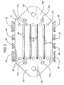
- Figure 2 is a front view of a filtration manifold.
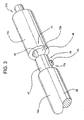
- Figure 3 is a perspective view of a keyed male design fitting and a fitting including a corresponding female socket.
- Figure 4 is a cross-sectional side view of a spring-ball plunger fitting and a fitting including a corresponding groove.
- Figure 5 is a representative cross-sectional side view of a fitting including at least one O-ring and a corresponding fitting including a region that may form a press-fit seal with the O-ring.
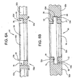
- Figure 6A is a cross-sectional side view of a slotted engagement.
- Figure 6B is a cross-sectional top view of the slotted engagement of Figure 6A .
- Filtration assemblies may include first and second end pieces, at least one filtration unit between the first and second end pieces, and a manifold.
- the manifold which may or may not function as one of the end pieces, includes fluid passages that channel feed fluid, permeate and/or retentate to and/or from fluid passages in the filtration units.
- the filtration assembly may further include one or more, e.g., between two and eight, alignment rod arrangements extending between the end pieces and aligning the filtration units between the end pieces with the fluid passages in the filtration units fluidly communicating among themselves and with the fluid passages in the manifold.
- the alignment rod arrangements may be configured in a wide variety of ways.
- a filtration assembly 10 includes at least one filtration unit 13 between first and second end pieces, e.g., first and second end plates 66a, 66b.
- the filtration assembly 10 may further include a manifold 11 for directing feed fluid, permeate and/or retentate to and from the filtration units 13.
- the manifold 11 may be located between the first and second end plates 66a, 66b and may serve as an intermediate end piece for the filtration units 13 on each side of the manifold 11.
- At least one alignment rod arrangement 71 extends between an end plate 66a, 66b and the manifold 11, or through the manifold 11 between the first and second end plates, and may align the filtration units 13, the manifold 11, and/or the end plates 66a, 66b.
- the alignment rod arrangement may be configured in a number of different ways.
- the alignment rod arrangement may comprise any suitable material, including, for example, a metal such as stainless steel or a plastic, and may have any suitable configuration, such as, for example, a generally cylindrical configuration.
- Different filtration assemblies may have different sizes depending, e.g., on the number of filtration units, and the size of the alignment rod arrangement may be varied accordingly.
- the alignment rod arrangement may include at least two removably attachable components that may be configured in any of a variety of different ways.
- the alignment rod arrangement 71 may include first and second components 72a, 72b removably attachable to one another between the end pieces.
- An alignment rod arrangement component may be positioned anywhere on the assembly and may include at least one rod, at least one fitting, or both a rod(s) and a fitting(s).
- Each of the components of the alignment rod arrangement may have identical or different lengths. Further, for many embodiments, each of the components of the alignment rod arrangement may have the same diameter when coupled together, e.g., coupled components may have a consistent or uniform diameter along the length of the coupled alignment rod arrangement.
- the first alignment rod component 72a may be slidably mounted on an end plate 66b.
- the first component may pass partially or completely through the end plate, e.g., the second end plate 66b.
- the first component may be mounted external to the end plate, e.g., to a collar fixed to the end plate.
- the second component 72b may be positioned e.g., removably or fixedly positioned, on the manifold 11, for example, in a socket 21a of the manifold, as shown in Figure 2 .
- the first alignment rod component 72a may include a rod 69 and a fitting 73a at one end of the rod 69.
- the rod 69 may extend from the fitting 73a to or through the second end plate 66b.
- the second alignment rod component 72b may include a shorter stub having a fitting 21b on one end that mates with the manifold fitting 21a and a fitting 73b on the other end.
- the first and second alignment rod components 72a, 72b may mate at the fittings 73a, 73b and may have the same diameter when coupled together.
- the second alignment rod component may be positioned on the first end plate, and the rod may extend slidably through a through hole in the manifold to the second end plate.
- the slidably disposed alignment rod component e.g., the first component 72a, may have a length that is longer than the length of the other alignment rod component, e.g., the second component 72b.
- the corresponding fittings of the alignment rod arrangement may be configured in any of a variety of different ways.
- a fitting may be releasably connectable to another fitting, e.g., on another component of the alignment rod arrangement.
- a fitting may include any structure, including a socket or a receptacle or a detent mechanism.
- the fittings are capable of both securely attaching to another fitting, e.g., a corresponding fitting, and detaching from that other fitting.
- a fitting may include a keyed male design or a female socket design.
- a fitting 73a of a first component 72a of the alignment rod arrangement may include a keyed male design 74
- a fitting 73b of a second component 72b may include a corresponding female socket design 75.
- the keyed male design 74 may be mounted to the rod 69 and may include a stud 47 and a protuberance 45.
- the female socket design 75 may include a bore 48 which receives the stud 47 and is coaxially disposed in one end of the second component 72b, a longitudinal groove 46 in the wall of the bore 48, and a groove (not shown) in the wall of the bore 48 which intersects and extends perpendicular to the longitudinal groove 46 circumferentially away from the longitudinal groove 46.
- the keyed male design 74 may correspond with and engage the corresponding female socket design 75.
- the rod 69 may be slid longitudinally and the stud 47 of keyed male design 74 may be inserted into the bore 48 of corresponding female socket design 75 with the protuberance 45 engaged in the longitudinal groove 46 of the female socket design 75.
- the rod 69 including the alignment rod component 72a and the keyed male design 74 may be rotated about the axis of the rod 69 to move the protuberance 45 out of engagement with the longitudinal groove 46 and into engagement with the groove perpendicular to the longitudinal groove 46.
- the first and second components 72a, 72b are locked so that first and second components may not be longitudinally pulled apart and the rod 69 may not be axially slid without rotating the protuberance 45 back into engagement with the longitudinal groove 46.
- the coupled components 72a, 72b may form an alignment rod arrangement that has a uniform outer diameter along the length of the alignment rod arrangement.
- the rod 69 including the keyed male design 74 may be rotated in a direction that slides the protuberance 45 through the perpendicular groove and into the longitudinal groove 46.
- the rod 69 may slide longitudinally away from the corresponding female socket design 75.
- the first and second components may then be longitudinally pulled away from each other and apart.
- a fitting may include a spring ball plunger or a corresponding groove to accept the plunger.
- a fitting 73a of a first component 72a e.g., the rod 69 of the alignment rod arrangement may include a spring ball plunger 76 on a male design 74.
- the spring ball plunger 76 may be positioned on a stud 47.
- the spring ball plunger may include one or more ball plungers positioned on a spring (not shown) under tension, biasing each ball plunger radially outwardly from the stud 47.
- a fitting 73b of a second component 72b may include a female design 75 having a bore 48 and a corresponding circumferential groove 77 in the wall of the bore 48 to accept the ball plunger(s).
- the groove 77 may extend radially into the wall of the bore 48.
- the bore 48 may include a flared external edge 49 that is capable of engaging and depressing each ball plunger into the stud 47.
- the fitting 73a including the spring ball plunger 76 may correspond with and engage the corresponding fitting 73b including the groove 77 to accept the spring ball plunger.
- rod 69 may be slid longitudinally toward the second component 72b and the stud 47 of the fitting of the first component 72a may be inserted into the bore 48 of corresponding fitting of the second component 72b.
- the spring ball plunger 76 may engage the flared edge 49 of the bore 48, depressing the spring ball plungers. Upon further insertion of the stud 47 into the bore 48, each spring ball plunger 76 may be radially depressed into the stud 47 by the inside wall of bore 48. Upon full insertion of the stud 47 into the bore 48, the spring ball plunger may reach the corresponding groove 77, the spring tension forcing each plunger to rise up into, and remain in, the groove 77. Upon engagement of the spring ball plunger 76 with the groove 77, the first and second components may be securely fastened.
- the coupled components 72a, 72b may form an alignment rod arrangement that has a uniform outer diameter along the length of the alignment rod arrangement.
- the rod 69 may be pulled longitudinally away from the second connector 72b.
- the edges of the groove 77 may depress the spring ball plungers into the stud 47 and the fitting with the depressed spring ball plungers 76 may be pulled longitudinally out of the bore 48, so that the stud 47 may be pulled longitudinally away from the bore 48 and the first and second components may detach.
- a fitting may include a resilient O-ring that forms a press fit when the O-ring is engaged with a bore.
- a fitting 73a of the first component 72a e.g., the rod 69
- the fitting 73b of a second component 72b may include a female design 75 having a bore 48 which receives the stud 47 and includes a region 79 in the wall of the bore 48 that may form a press fit when the O-ring 78 is engaged in the bore 48.
- the bore 48 may include a flared external edge 49 that is capable of engaging and compressing the O-ring.
- the fitting 73a including the O-ring 78 may correspond with and engage the corresponding fitting 73b including the bore 48.
- the rod 69 may be longitudinally slid toward the second component 72b and the stud 47 of the fitting of the first component 72a may be inserted into the bore 48 of the corresponding fitting of the second component 72b.
- each O-ring 78 may engage the flared edge 49, compressing the O-ring.
- each O-ring may be resiliently compressed between the stud 47 and the region 79 of the bore 48 and may form a tight, frictional fit within the bore 48.
- the coupled components 72a, 72b may form an alignment rod arrangement that has a uniform outer diameter along the length of the alignment rod arrangement.
- the rod 69 may be longitudinally slid away from the second connector 72b and the fitting with the O-rings 78 may be pulled longitudinally away from the bore 48, disengaging the press fit, so that the stud 47 may be pulled longitudinally away from and out of the bore 48 and the first and second components 72a, 72b may detach.
- the releasably connectable fittings may be configured in numerous other ways.
- the fitting having the bore may be part of the first component while the fitting having the stud may be part of the second component.
- the above fittings are merely exemplary and do not exclude the possibility of a removable attachment attainable from other types of fittings.
- a fitting may include any structure that is capable of both securely attaching to another fitting, e.g., a corresponding fitting, and detaching from that other fitting.
- Other fittings may include, but are not limited to, threaded studs and correspondingly threaded nuts.
- the fittings of the alignment rod arrangements previously described are positioned on the first and second components of each alignment rod arrangement, one or more of the fittings may be positioned elsewhere in the filtration assembly.
- one of the fittings may be associated with the manifold or an end piece in any of a variety of different ways.
- the fitting may be bonded or welded or threaded to the manifold or an end piece.
- one of the fittings, e.g., the fitting having the bore may be integrally formed within the manifold or end piece, for example, by machining the fitting in one side of the manifold or end piece.
- the detachably connectable alignment rod arrangement may be no more than a single component which includes, for example, a rod and the corresponding fitting, e.g., the fitting having the stud, on one end of the rod.
- one or more fittings having the bore may be formed in one side of the manifold, and one or more rods which include fittings having the stud may be slidably disposed in an end piece.
- Each fitting on the rod may be similarly coupled and uncoupled from the corresponding fitting on the manifold as previously described with respect to the fittings on the first and second components of the alignment rod arrangement.
- the end pieces may be configured in any of a variety of different ways.
- the end pieces may be configured as end plates 66a, 66b.
- Each end plate 66a, 66b may include no fluid passages and may plug any flow passages in the adjacent filtration unit that open onto the end plate.
- the end plates may include additional fluid passages that fluidly communicate with the flow passages in the adjacent filtration unit.
- a filtration manifold may also function as an end piece on one or both ends of the filtration assembly or intermediate the two end plates 66a, 66b, as shown in Figure 1 , for example.
- Some embodiments may have two end plates which serve as end pieces and no manifolds, other embodiments may have two manifolds which serve as end pieces and no end plates, and still other embodiments may have a combination of one or more end plates and one or more manifolds which serve as end pieces.
- One or both of the end pieces may further comprise one or more holes, fittings, or sockets in which, for example, an alignment rod arrangement may be disposed.
- the hole or socket may further comprise a bushing in which the alignment rod arrangement may be slidably disposed.
- end plate 66b may include a bushing 67 through which the rod 69 may be slidably disposed, e.g., allowing the rod 69 to slide in both directions relative to the end plate 66b as represented by the arrow A.
- a filtration unit may have any size and shape and may be configured in a variety of different ways.
- a filtration unit may include a filtration medium cooperatively arranged with a casing.
- the filtration unit may be part of a plate and frame device in which separate filtration medium sheets and frames are compressed and sealed between one another.
- the filtration unit may comprise a filtration cassette in which a filtration medium is integrally fitted with and sealed to a casing.
- each filtration unit 13 may include a filtration medium 60 arranged with a casing 61 to define a feed side 62a and a permeate side 62b of the filtration medium 60.
- a filtration unit 13 may also include at least one feed passage 63 fluidly communicating with the feed side 62a of the filtration medium 60 and at least one permeate passage 65 fluidly communicating with the permeate side 62b of the medium.
- a filtration unit 13 may additionally include at least one retentate passage 64 fluidly communicating with the feed side 62a of the filtration medium. Filtration assemblies arranged for direct flow or dead-end flow filtration may not have any retentate passages.
- the filter medium may be permeable and may have any suitable treatment characteristic.
- the filtration medium may have, or may be modified to have, any of several characteristics.
- the filtration medium may have a positive, negative, or neutral electrical charge; it may be liquiphobic or liquiphilic, including, for example, hydrophobic or hydrophilic, or oleophobic or oleophilic; it may include attached functional groups, such as ligands, that can chemically bind to substances in the fluid.
- the filtration medium may be formed from, impregnated with, or otherwise contain a variety of materials, such as sorbents, ion exchange resins, enzymes, or catalysts, that may chemically or physically bind, react with, or otherwise alter substances in the fluid.
- the filtration medium may have any of a wide range of molecular cutoffs or removal ratings, including, for example, from ultraporous or nanoporous or finer to microporous or coarser.
- the filtration medium may thus function as a treatment medium of any type, including a capture medium, a separation medium, or a filter medium.
- the casing of the filtration unit may include any suitable housing for the filtration medium, e.g., a frame.
- the filtration unit may further comprise an exterior which may include, e.g., the exterior of the casing, and along which an alignment rod arrangement may extend.
- the filtration unit 13 may comprise an exterior 14 along which an alignment rod arrangement 71 may extend.
- the exterior 14 of the filtration unit may be configured so that the alignment rod arrangement fits in close proximity, e.g., contacts, along the exterior 14 of the filtration unit.
- a filtration assembly may further include one or more fixed alignment rods which extend between the end plates or between an end plate and a manifold along with one or more removably attachable alignment rod arrangements.
- a fixed alignment rod may be one that is not removable without disassembling the filtration assembly, and a filtration assembly may include any number of fixed alignment rods and any number of alignment rod arrangements in combination. Some embodiments of the filtration assembly may include one or more alignment rod arrangements and no fixed alignment rods.
- a filtration unit may include first and second edges along which one or more fixed alignment rods and/or one or more alignment rod arrangements may align the filtration units.
- an alignment rod arrangement 71 may align the filtration units along a first edge 17a of the filtration units 13 and a fixed alignment rod 50 may align the filtration units 13 along a second edge 17b.
- the exterior of each casing may include a cutout in which the fixed alignment rods and/or the alignment rod arrangements may be positioned.
- each casing may include one or more through holes, and one or more removably attachable alignment rod arrangements may be positioned along the interior of each filtration unit within the through holes of the casings to align the filtration units.
- the alignment rod arrangements may be long enough to extend not only through all of the through holes of the aligned filtration units in the filtration assembly but also through and somewhat beyond an end piece.
- the alignment rod arrangements may then be detached and reattached as previously explained by manipulating the portion of the alignment rod arrangement which extends beyond the end piece and sliding the rod of the alignment rod arrangement longitudinally through the through holes of one or more filtration units.
- the filtration assembly may be arranged in any of a variety of different ways.
- at least one filtration unit may be positioned between the first and second end pieces.
- at least one filtration unit may be positioned between an end piece and one or both sides of a manifold.
- at least a plurality of filtration units 13 may be positioned between the first end plate 66a and the first side 16a of manifold 11 and a plurality of filtration units 13 may be positioned between the second end plate 66b and the second side 16b of manifold 11, the manifold 11 serving as an intermediate end piece.
- all of the filtration units may be positioned between one end piece on one end of the filtration assembly and one side of the manifold on the other end of the filtration assembly.
- the filtration assembly may include a sequence of any number of filtration units positioned between two end pieces or between a manifold and an end plate.
- the sequence may include a series of adjacent filtration units.
- the filtration assembly 10 shown in Figure 1 includes four adjacent filtration units 13 between end plate 66a and manifold 11 and four adjacent filtration units 13 between end plate 66b and manifold 11.
- the filtration assembly may further include a manifold that may be configured in any of a variety of different ways.
- a filtration manifold 11 may comprise a body 15 having first and second opposite sides 16a, 16b.
- the body of the manifold may comprise any suitable material, including, for example, a metal such as stainless steel, or a plastic, and may have any suitable configuration, such as, for example, a generally hexagonal configuration as shown in Figure 2 .
- Different separation processes may require different types and/or sizes of filtration units, and the shape and size of the manifold may be varied accordingly.
- the body of the manifold may include any or all of permeate collection passages, feed passages, and retentate passages.
- a tangential flow filtration manifold may include one or more feed inlets 20 and feed passages 21, one or more retentate passages 22 and retentate outlets 23, one or more permeate passages 24 and permeate outlets 25, and/or one or more sampling ports 26.
- a dead-end flow or direct flow filtration manifold may include feed passages and permeate passages but may lack retentate passages.
- the body of the manifold may include first and second permeate collection passages that may be configured in any of a variety of different ways.
- the manifold may, or may not, be configured as disclosed in United States Provisional Patent Application No. 60/874,012 entitled Filtration Assemblies, Filtration Manifolds, Filtration Units, and Methods of Channeling Permeate, which listed Roger Gagnon, Thomas Scholz, Martin Weinstein, Sylvia Messier, and Steven Pearl as an inventor and which was filed on December 11, 2006.
- the manifold may be bidirectional, i.e., any or all of the permeate fluid, feed fluid, and/or retentate fluid may flow into, or from, the manifold in at least two different, e.g., opposite, directions.
- the manifold may be unidirectional, i.e., any or all of the permeate fluid, feed fluid, and/or retentate fluid may flow into, or from, the manifold in only one direction.
- the body of the manifold may also include any of a variety of coupling elements that may connect the manifold within a filtration assembly in any of a variety of different ways.
- Coupling elements may include holes, sockets, fittings, bolts, rivets, screws, or any other structure that may securely attach the filtration manifold within the filtration assembly.
- the body 15 may include multiple sockets 21a that may connect to alignment rod arrangements and/or fixed alignment rods which align the filtration units within the filtration assembly.
- the body 15 also includes two through holes 20 that may pass through the body, and the filter assembly 10 further includes compression rod arrangements having compression rods 70 that extend through the through holes in the manifold and in the end pieces, sealingly compressing the end pieces, manifold, and filtration units together with their respective fluid passages communicating with one another.
- the compression rod arrangements may have any of numerous configurations.
- compression rod arrangements may, or may not, be configured as disclosed in United States Provisional Patent Application No. 60/873,980 entitled Filtration Assemblies and Methods of Maintaining Compression of Filtration Units in Filtration Assemblies, which listed Roger Gagnon, Franco Morizio, and Robert Ieraci as an inventor and which was filed on December 11, 2006.
- Some embodiments may not include separate compression rod arrangements.
- the alignment rod arrangements may then serve to establish and/or maintain compression of the filtration assembly as well as align the filtration units and the manifold.
- the alignment rod arrangement may be assembled into the filtration assembly in any of a variety of different ways.
- the alignment rod arrangement 71 may extend between two end pieces, e.g., the manifold 11 and the end plate 66b and may align the filtration units 13 along the exterior of the filtration units 13 with the respective feed, retentate, and permeate passages 21, 63; 22, 64; 24, 65 of the manifold 11 and the filtration units 13 properly communicating with one another.
- an alignment rod arrangement may be configured to move laterally rather than longitudinally to allow the filtration units to be installed and/or uninstalled.
- an alignment rod arrangement may include at least three interconnected components configured in any of a variety of different ways to allow at least one of the components to move laterally.
- the alignment rod arrangement 51 may include three components 52a, 52b, and 52c removably attached between the end pieces.
- the alignment rod arrangement 51 may be positioned within the filtration assembly as described for the first embodiment of the alignment rod arrangement 71, for example, between two end plates or between an end plate and a manifold.
- alignment rod arrangement 51 may extend between the manifold 11 and an end plate 66a.
- the alignment rod arrangement 51 may also align filtration units 13 as described for the first embodiment.
- the first removably attachable component 52a may comprise a short stub which may be permanently or removably attached on one end to an end piece, e.g., the end plate 66a, and may include a fitting 53a on an opposite end.
- the second removably attachable component 52b may similarly comprise a short stub which may be permanently or removably attached on one end to the manifold 11 and may include a fitting 53b on an opposite end.
- the third removably attachable component 52c may include a rod 54 and a first fitting 53c on one end of the rod 54 and a second fitting 53d on an opposite end of the rod 54.
- the first, second, and third components 52a, 52b, 52c may mate at the fittings 53a, 53b, 53c, 53d.
- the third removably attachable component 52c may connect and be detachable from the first and/or second components 52a, 52b.
- the first fitting 53c of the rod 54 may be releasably connectable to the fitting 53a of the first component 52a and the second fitting 53d of the rod 54 may be releasably connectable to the second fitting 53b of the second component 52b, permitting the alignment rod 54 to detach from fittings 53a and 53b and move laterally from between the end plate 66a and the manifold 11 to provide a space for the installation or removal of the filtration units 13.
- the fittings of the alignment rod arrangement of the second embodiment may be configured in any of a variety of different ways.
- the fittings of the second embodiment may include slot and bar engagement fittings.
- the fittings 53a, 53b of the first and second components 52a, 52b, respectively may each include a slot 56 having a depression 77.
- the first and second fittings 53c, 53d of the third component 52c, e.g., the rod 54 may each include a bar 55 that may also comprise a detent mechanism such as a spring ball plunger 76.
- the bars 55 of the fittings 53c, 53d of the rod 54 may engage with the slots 56 of the fittings 53a, 53b of the first and second components 52a, 52b, respectively, so that the rod 54 may be attached to fittings 53a, 53b.
- the bars 55 of the rod 54 may be moved laterally into or out of the slots 56.
- a detent mechanism such as the spring ball plunger 76, may also engage with the depression 77 to even more securely hold the rod 54 in place.
- alignment rod arrangements of the invention may have one, two, or three components
- alignment rod arrangements of the invention may include any number of removably attached components, for example, four or more removably attached components.
- Methods according to the invention may include removing and/or installing one or more filtration units from/into a filtration assembly in any of a variety of different ways.
- One or more components of an alignment rod arrangement detach, e.g., the fittings disconnect, between opposed end pieces to allow removal or insertion of the filtration units.
- the first component 72a e.g., the rod 69
- the fittings may be disconnected in any manner appropriate for the releasably connectable fittings, for example, in any manner previously described for the fittings.
- An alignment rod component moves e.g., slides, longitudinally along the interior or the exterior of the filtration units to disconnect the fittings.
- the fittings 73a, 73b may be disconnected and the first component 72a, including the alignment rod 69, may slide along, e.g., through, one end plate 66b through the bushing 67 and away from the manifold 11, as shown by arrow A. Longitudinally moving, e.g., sliding, the rod 69 provides a space for loading or unloading the filtration units.
- Methods of removing and/or installing a filtration unit from/into a filtration assembly further comprise removing and/or installing at least one filtration unit between the first and second end pieces in a variety of different ways.
- at least one filtration unit 13 may be removed and/or installed between end plates 66a and 66b, or between the manifold 11 and either of the end plates 66a, 66b, after the compression rods 70 have been loosened.
- Detaching components of the alignment rod arrangement 71 and sliding the rod 69 away from the manifold 11 along the end plate 66b provides a variable space, e.g., a smaller or larger space, through which one or multiple filtration units 13 may be removed from and/or installed into the filtration assembly 10 sequentially or simultaneously by moving the filtration unit(s) laterally through the space.
- a variable space e.g., a smaller or larger space
- Methods of removing and/or installing a filtration unit from/into a filtration assembly may further comprise reattaching the components of the alignment rod arrangement between the end pieces in a variety of different ways.
- One of the alignment rod components may slide longitudinally to close the space for the loading of the filtration units.
- the first alignment rod component including rod may slide longitudinally through one end piece and toward the other end piece.
- the alignment rod 69 may slide through bushing 67 of the second end plate 66b through and toward the manifold the 11 to close the space that was opened for the loading of the filtration units, as shown by arrow A. Once the first and second components contact one another, the fittings may be reattached.
- first component 72a may reattach to second component 72b by reconnecting the first fitting 73a to the second fitting 73b.
- the first and second fittings may be reconnected in any manner appropriate for the releasably connectable fittings, for example, in a manner described for the fittings above.
- Reattaching the components of the alignment rod arrangement may further include aligning the filtration units and end pieces, e.g., the end plates and/or manifold, along the alignment rod arrangement in any of a variety of different ways.
- sliding the first component 72a including the rod 69 toward the manifold 11 may include closely positioning, e.g., contacting, the rod 69 and the filtration units 13, thereby maintaining alignment and proper fluid communication of the respective fluid passages 21, 63; 22, 64; 24, 65 in the manifold 11 and the filtration units.
- the alignment rod arrangement may align filtration units within a filtration assembly in any of a variety of different ways.
- the alignment rod arrangement may align multiple filtration units in a sequence with each other and/or with one or more manifolds.
- the alignment rod arrangement may extend along the exterior of the filtration units.
- alignment rod arrangement 71 may extend along and contact the exterior 14 of the filtration units 13.
- the alignment rod arrangement may fit inside a cut-out in the exterior of the filtration unit to align the filtration units.
- the alignment rod arrangement may slide through through holes in the interior of the filtration units to align the filtration units.
- the filtration units may be aligned by the alignment rod arrangements for any of a variety of different purposes.
- the alignment rod arrangement may align the feed passage(s) of a filtration unit to fluidly communicate with the feed passage(s) of an adjacent filtration unit in the sequence and/or the feed passage(s) of a manifold.
- the alignment rod arrangement may align the permeate passage(s) of a filtration unit to fluidly communicate with the permeate passage(s) of an adjacent filtration unit in the sequence and/or the permeate passage(s) of a manifold.
- the alignment rod arrangement may align the retentate passage(s) of a tangential flow filtration unit to fluidly communicate with the retentate passage(s) of an adjacent filtration unit in the sequence and/or the retentate passage(s) of a manifold. Attachment of the components of the alignment rod arrangement may move the filtration units into alignment with each other and/or with the manifold, and the assembled alignment rod arrangement may maintain the filtration units in alignment with each other as well as with the manifold.
- the alignment rod arrangement may provide a sequence of filtration units including aligned feed and permeate passages that may also be aligned with at least one of the feed and permeate passages of the manifold(s), respectively.
- the alignment rod arrangement may additionally provide a sequence of filtration units including aligned retentate passages that may also be aligned with at least one of the retentate passages of the manifold(s), respectively.
- an alignment rod component may move laterally away from the filtration units or the end pieces to disconnect the fittings.
- the first fitting 53c of the third component 52c of the alignment rod arrangement may disconnect from the fitting 53a of the first component 52a and the second fitting 53d of third component 52c may disconnect from fitting 53b of the second component 52b.
- the third component 52c including the rod 54 may then move laterally away from the filtration units and the end pieces.
- the bars 55 of the fittings 53c, 53d of the third component 52c may disengage from the slots 56 of the fittings 53a, 53b of first and second components 52a, 52b between the end pieces.
- a detent mechanism such as a spring ball plunger 76, may also disengage from the recesses 77.
- the rod 54 may move laterally away from end plate 66a and manifold 11 to produce a space for loading and/or unloading filtration units 13.
- the methods of the second embodiment may further include installing and/or uninstalling the filtration units as described for the first embodiment.
- the three releasably attachable components of the second embodiment may also reattach between the end pieces in a variety of different ways.
- the third component may move laterally to close the space for the loading of the filtration units.
- the third component 52c including the rod 54 may move laterally toward or between the end pieces, e.g., the manifold 11 and end plate 66a, to close the space for loading and unloading the filtration units 13.
- the third component 52c may reattach to each of the first and second releasable components 52a, 52b by reconnecting the first and second fittings of the third component 53c, 53d to the fittings of the first and end pieces 53a, 53b, respectively, between the end pieces.
- bars 55 of fittings 53c, 53d of third component 52c may reengage the slots 56 of the fittings 53a, 53b of the first and second components 52a, 52b, respectively.
- a detent mechanism such as a spring ball plunger 76, may also reengage with groove 77.
- the third component 52c may thus be reattached to first and second components 52a, 52b and may align the filtration units 13 as described for the first embodiment.
- moving the rod 54 of the alignment rod arrangement 51 laterally toward or between the end plate 66a and the manifold 11 may include aligning the filtration units 13, the end plate 66a, and the manifold 11 with each other.
- the second embodiment has been described with respect to an alignment rod which completely separates from the first and second components
- other embodiments may include an alignment rod which remains attached to one of the first and second components of the alignment rod arrangement.
- the slot and bar fitting of one of the first and second components may be changed to a pivot arrangement which pivotably connects the component to the alignment rod.
- the alignment rod may then be moved laterally by pivoting the alignment rod about the pivot arrangement away from, or toward, the filtration units and may be detached from, or attached to, the other of the first and second components by, for example, a slot and bar fitting.
Abstract
Description
- The invention relates to filtration assemblies and methods of installing filtration units into filtration assemblies for any and all types of separation processes. More particularly, it relates to filtration assemblies including removably attachable alignment rod arrangements.
-
EP 0 322 604 ,EP 0535 446 andUS 4 849 102 disclose filtration units compressed between end plates by rods having both an alignment and compression function. -
US 3 831 763 discloses filtration units hold in place by alignment rods and being compressed by separate compression rods. However the filtration units cannot be removed by simply loosening the compression rods. - Filtration assemblies embodying the invention may be arranged for tangential flow filtration or for direct flow or dead-end flow filtration. For direct flow or dead-end flow filtration, process or feed fluid is directed to a permeable filtration medium. All of the feed fluid then passes through the filtration medium as filtrate or permeate, except any substances in the fluid that are retained by the filtration medium. For tangential flow filtration, feed fluid is directed tangentially along a permeable filtration medium. A portion of the feed fluid passes through the filtration medium as permeate, and the remaining portion of the feed fluid, the concentrate or retentate, is directed away from the filtration medium.
- Filtration assemblies embodying the invention include at least one filtration unit, and for many embodiments several filtration units, aligned and compressed between first and second end pieces. At least one alignment rod arrangement extends between the end pieces and align the filtration units. An end piece further comprises a fitting to which an alignment rod arrangement may be removably attachable. The filtration assemblies may further comprise one or more manifolds that may be arranged with the filtration units to feed fluid to the filtration units and/or to collect fluid from the filtration units.
- The alignment rod arrangement is removably attachable to the filtration assembly, and the alignment rod arrangement is removably attached through releasably connectable fittings. Detachment of the alignment rod assembly may provide a space for removing one or more filtration units from the assembly and installing one or more new filtration units into the assembly. After installation, the alignment rod arrangement may reattach to align the filtration units.
- An alignment rod arrangement includes at least one rod and at least one fitting. The alignment rod arrangement may be slidably mounted to an end piece. .
- The present invention provides highly efficient filtration assemblies according to cl. 1 and methods of installing filtration units in filtration assemblies according to cl. 1.
- In accordance with the invention, filtration assemblies comprises first and second end pieces and at least one filtration unit between the first and second end pieces. The assembly further comprises at least one alignment rod arrangement extending between the end pieces and aligning the filtration unit or units. The alignment rod arrangement may include at least first and second components removably attachable to one another between the end pieces.
- In accordance with the invention, filtration assemblies comprise at least one filtration unit between the first and second end pieces, and the at least one alignment rod arrangement positioned to align the filtration unit or units between the end pieces. The alignment rod arrangement includes an alignment rod mounted between the end pieces to slide longitudinally along one end piece and away from the other end piece.
- In accordance with another aspect of the invention, methods of installing a filtration unit into a filtration assembly may comprise detaching components of an alignment rod arrangement between first and second end pieces, installing at least one filtration unit according to cl. 5 between the end pieces, and reattaching the components of the alignment rod arrangement between the end pieces. Reattaching the components of the alignment rod arrangement includes aligning the filtration unit or units along the alignment rod arrangement.
- In accordance with the invention, methods of installing a filtration unit into a filtration assembly comprise sliding an alignment rod longitudinally in one direction along one end piece and away from an opposed end piece and installing at least one filtration unit between the end pieces. The method may further include sliding the alignment rod longitudinally in the opposite direction along the one end piece and toward the opposed end piece. Sliding the alignment rod may include aligning the filtration unit or units along the alignment rod arrangement.
- Filtration assemblies and methods of installing filtration units into filtration assemblies according to the present invention have many advantages. For example, alignment rod arrangements embodying the invention greatly facilitate displacement of the alignment rod arrangement and loading and unloading of the filtration units. Displacement of the alignment rod arrangement may provide a large enough space through which one or more filtration units may pass when loading or unloading the assembly. Moreover, the space provided by the displacement of the alignment rod arrangement may permit the removal of multiple filtration units simultaneously. Additionally, displacement of the alignment rod arrangement may also permit the removal of a filtration unit from anywhere within a sequence of filtration units without having to remove some or all of the other filtration units in the sequence. Moreover, the displacement of the alignment rods may allow a number of filtration units to be installed or removed without having to slide filtration units one at a time through a small area in the assembly. Accordingly, the alignment rod arrangements of the claimed filtration assemblies may provide increased flexibility, speed, and ease with respect to filtration unit installation and removal, as well as filtration assembly construction and disassembly.
- A further advantage of the filtration assemblies and methods of the invention is that the alignment rod arrangement may align any or all of the feed passages, permeate passages, and retentate passages of adjacent filtration units to fluidly communicate with each other and/or with the feed passages, permeate passages, and retentate passages, respectively, of one or more manifolds. Alignment of the feed, permeate, and retentate passages in this manner may advantageously facilitate the flow of feed, permeate, and/or retentate from one filtration unit to an adjacent filtration unit and from the filtration units to one or more manifolds.
-
Figure 1 is a top view of a filtration assembly. -
Figure 2 is a front view of a filtration manifold. -
Figure 3 is a perspective view of a keyed male design fitting and a fitting including a corresponding female socket. -
Figure 4 is a cross-sectional side view of a spring-ball plunger fitting and a fitting including a corresponding groove. -
Figure 5 is a representative cross-sectional side view of a fitting including at least one O-ring and a corresponding fitting including a region that may form a press-fit seal with the O-ring. -
Figure 6A is a cross-sectional side view of a slotted engagement. -
Figure 6B is a cross-sectional top view of the slotted engagement ofFigure 6A . - Many different filtration assemblies may embody one or more aspects of the invention. Filtration assemblies according to the invention may include first and second end pieces, at least one filtration unit between the first and second end pieces, and a manifold. The manifold, which may or may not function as one of the end pieces, includes fluid passages that channel feed fluid, permeate and/or retentate to and/or from fluid passages in the filtration units. The filtration assembly may further include one or more, e.g., between two and eight, alignment rod arrangements extending between the end pieces and aligning the filtration units between the end pieces with the fluid passages in the filtration units fluidly communicating among themselves and with the fluid passages in the manifold. The alignment rod arrangements may be configured in a wide variety of ways.
- One example of a filtration assembly is shown in
Figure 1 . Afiltration assembly 10 includes at least onefiltration unit 13 between first and second end pieces, e.g., first andsecond end plates filtration assembly 10 may further include amanifold 11 for directing feed fluid, permeate and/or retentate to and from thefiltration units 13. Themanifold 11 may be located between the first andsecond end plates filtration units 13 on each side of themanifold 11. At least onealignment rod arrangement 71 extends between anend plate manifold 11, or through themanifold 11 between the first and second end plates, and may align thefiltration units 13, themanifold 11, and/or theend plates - The alignment rod arrangement may be configured in a number of different ways. The alignment rod arrangement may comprise any suitable material, including, for example, a metal such as stainless steel or a plastic, and may have any suitable configuration, such as, for example, a generally cylindrical configuration. Different filtration assemblies may have different sizes depending, e.g., on the number of filtration units, and the size of the alignment rod arrangement may be varied accordingly.
- The alignment rod arrangement may include at least two removably attachable components that may be configured in any of a variety of different ways. As shown in
Figure 1 , for example, thealignment rod arrangement 71 may include first andsecond components Figure 1 , the firstalignment rod component 72a may be slidably mounted on anend plate 66b. For many embodiments, the first component may pass partially or completely through the end plate, e.g., thesecond end plate 66b. For other embodiments, the first component may be mounted external to the end plate, e.g., to a collar fixed to the end plate. Thesecond component 72b may be positioned e.g., removably or fixedly positioned, on the manifold 11, for example, in asocket 21a of the manifold, as shown inFigure 2 . As shown inFigures 3-5 , the firstalignment rod component 72a may include arod 69 and a fitting 73a at one end of therod 69. Therod 69 may extend from the fitting 73a to or through thesecond end plate 66b. The secondalignment rod component 72b may include a shorter stub having a fitting 21b on one end that mates with the manifold fitting 21a and a fitting 73b on the other end. The first and secondalignment rod components fittings first component 72a, may have a length that is longer than the length of the other alignment rod component, e.g., thesecond component 72b. - The corresponding fittings of the alignment rod arrangement may be configured in any of a variety of different ways. For example, a fitting may be releasably connectable to another fitting, e.g., on another component of the alignment rod arrangement. A fitting may include any structure, including a socket or a receptacle or a detent mechanism. For many embodiments, the fittings are capable of both securely attaching to another fitting, e.g., a corresponding fitting, and detaching from that other fitting.
- For example, a fitting may include a keyed male design or a female socket design. As shown in
Figure 3 , for example, a fitting 73a of afirst component 72a of the alignment rod arrangement may include a keyedmale design 74, and a fitting 73b of asecond component 72b may include a correspondingfemale socket design 75. The keyedmale design 74 may be mounted to therod 69 and may include astud 47 and aprotuberance 45. Thefemale socket design 75 may include abore 48 which receives thestud 47 and is coaxially disposed in one end of thesecond component 72b, alongitudinal groove 46 in the wall of thebore 48, and a groove (not shown) in the wall of thebore 48 which intersects and extends perpendicular to thelongitudinal groove 46 circumferentially away from thelongitudinal groove 46. The keyedmale design 74 may correspond with and engage the correspondingfemale socket design 75. For example, therod 69 may be slid longitudinally and thestud 47 of keyedmale design 74 may be inserted into thebore 48 of correspondingfemale socket design 75 with theprotuberance 45 engaged in thelongitudinal groove 46 of thefemale socket design 75. Upon full insertion of thestud 47 of the keyedmale design 74 into thebore 48 of the correspondingfemale socket design 75, therod 69 including thealignment rod component 72a and the keyedmale design 74 may be rotated about the axis of therod 69 to move theprotuberance 45 out of engagement with thelongitudinal groove 46 and into engagement with the groove perpendicular to thelongitudinal groove 46. Upon being out of engagement with thelongitudinal groove 46, the first andsecond components rod 69 may not be axially slid without rotating theprotuberance 45 back into engagement with thelongitudinal groove 46. Once engaged, the coupledcomponents rod 69, therod 69 including the keyedmale design 74 may be rotated in a direction that slides theprotuberance 45 through the perpendicular groove and into thelongitudinal groove 46. When theprotuberance 45 reaches thelongitudinal groove 46, therod 69 may slide longitudinally away from the correspondingfemale socket design 75. The first and second components may then be longitudinally pulled away from each other and apart. - In another example, a fitting may include a spring ball plunger or a corresponding groove to accept the plunger. As shown in
Figure 4 , a fitting 73a of afirst component 72a, e.g., therod 69 of the alignment rod arrangement may include aspring ball plunger 76 on amale design 74. Thespring ball plunger 76 may be positioned on astud 47. The spring ball plunger may include one or more ball plungers positioned on a spring (not shown) under tension, biasing each ball plunger radially outwardly from thestud 47. A fitting 73b of asecond component 72b may include afemale design 75 having abore 48 and a correspondingcircumferential groove 77 in the wall of thebore 48 to accept the ball plunger(s). Thegroove 77 may extend radially into the wall of thebore 48. Thebore 48 may include a flaredexternal edge 49 that is capable of engaging and depressing each ball plunger into thestud 47. The fitting 73a including thespring ball plunger 76 may correspond with and engage the corresponding fitting 73b including thegroove 77 to accept the spring ball plunger. For example,rod 69 may be slid longitudinally toward thesecond component 72b and thestud 47 of the fitting of thefirst component 72a may be inserted into thebore 48 of corresponding fitting of thesecond component 72b. Upon insertion of thestud 47 into thebore 48, thespring ball plunger 76 may engage the flarededge 49 of thebore 48, depressing the spring ball plungers. Upon further insertion of thestud 47 into thebore 48, eachspring ball plunger 76 may be radially depressed into thestud 47 by the inside wall ofbore 48. Upon full insertion of thestud 47 into thebore 48, the spring ball plunger may reach the correspondinggroove 77, the spring tension forcing each plunger to rise up into, and remain in, thegroove 77. Upon engagement of thespring ball plunger 76 with thegroove 77, the first and second components may be securely fastened. Again, the coupledcomponents rod 69 may be pulled longitudinally away from thesecond connector 72b. The edges of thegroove 77 may depress the spring ball plungers into thestud 47 and the fitting with the depressedspring ball plungers 76 may be pulled longitudinally out of thebore 48, so that thestud 47 may be pulled longitudinally away from thebore 48 and the first and second components may detach. - In still another example, a fitting may include a resilient O-ring that forms a press fit when the O-ring is engaged with a bore. For example, as shown in
Figure 5 , a fitting 73a of thefirst component 72a, e.g., therod 69, may include at least one O-ring 78, e.g., two O-rings, positioned in grooves in astud 47 of amale design 74. The fitting 73b of asecond component 72b may include afemale design 75 having abore 48 which receives thestud 47 and includes aregion 79 in the wall of thebore 48 that may form a press fit when the O-ring 78 is engaged in thebore 48. Thebore 48 may include a flaredexternal edge 49 that is capable of engaging and compressing the O-ring. The fitting 73a including the O-ring 78 may correspond with and engage the corresponding fitting 73b including thebore 48. For example, therod 69 may be longitudinally slid toward thesecond component 72b and thestud 47 of the fitting of thefirst component 72a may be inserted into thebore 48 of the corresponding fitting of thesecond component 72b. Upon insertion of thestud 47 into thebore 48, each O-ring 78 may engage the flarededge 49, compressing the O-ring. Upon full insertion of thestud 47 into thebore 48, each O-ring may be resiliently compressed between thestud 47 and theregion 79 of thebore 48 and may form a tight, frictional fit within thebore 48. Again, the coupledcomponents rod 69 may be longitudinally slid away from thesecond connector 72b and the fitting with the O-rings 78 may be pulled longitudinally away from thebore 48, disengaging the press fit, so that thestud 47 may be pulled longitudinally away from and out of thebore 48 and the first andsecond components - The releasably connectable fittings may be configured in numerous other ways. For example, the fitting having the bore may be part of the first component while the fitting having the stud may be part of the second component. Further, the above fittings are merely exemplary and do not exclude the possibility of a removable attachment attainable from other types of fittings. A fitting may include any structure that is capable of both securely attaching to another fitting, e.g., a corresponding fitting, and detaching from that other fitting. Other fittings may include, but are not limited to, threaded studs and correspondingly threaded nuts. Further, although the fittings of the alignment rod arrangements previously described are positioned on the first and second components of each alignment rod arrangement, one or more of the fittings may be positioned elsewhere in the filtration assembly. For example, one of the fittings, e.g., the fitting having the bore, may be associated with the manifold or an end piece in any of a variety of different ways. For example, the fitting may be bonded or welded or threaded to the manifold or an end piece. As yet another example, one of the fittings, e.g., the fitting having the bore, may be integrally formed within the manifold or end piece, for example, by machining the fitting in one side of the manifold or end piece. In many of these embodiments, the detachably connectable alignment rod arrangement may be no more than a single component which includes, for example, a rod and the corresponding fitting, e.g., the fitting having the stud, on one end of the rod. For example, one or more fittings having the bore may be formed in one side of the manifold, and one or more rods which include fittings having the stud may be slidably disposed in an end piece. Each fitting on the rod may be similarly coupled and uncoupled from the corresponding fitting on the manifold as previously described with respect to the fittings on the first and second components of the alignment rod arrangement.
- The end pieces may be configured in any of a variety of different ways. For example, as shown in
Figure 1 , the end pieces may be configured asend plates end plate end plates Figure 1 , for example. Some embodiments may have two end plates which serve as end pieces and no manifolds, other embodiments may have two manifolds which serve as end pieces and no end plates, and still other embodiments may have a combination of one or more end plates and one or more manifolds which serve as end pieces. One or both of the end pieces may further comprise one or more holes, fittings, or sockets in which, for example, an alignment rod arrangement may be disposed. The hole or socket may further comprise a bushing in which the alignment rod arrangement may be slidably disposed. For example, as shown inFigure 1 ,end plate 66b may include abushing 67 through which therod 69 may be slidably disposed, e.g., allowing therod 69 to slide in both directions relative to theend plate 66b as represented by the arrow A. - A filtration unit may have any size and shape and may be configured in a variety of different ways. For example, a filtration unit may include a filtration medium cooperatively arranged with a casing. The filtration unit may be part of a plate and frame device in which separate filtration medium sheets and frames are compressed and sealed between one another. Alternatively, the filtration unit may comprise a filtration cassette in which a filtration medium is integrally fitted with and sealed to a casing.
- As shown in
Figure 1 , eachfiltration unit 13 may include afiltration medium 60 arranged with acasing 61 to define afeed side 62a and apermeate side 62b of thefiltration medium 60. Afiltration unit 13 may also include at least onefeed passage 63 fluidly communicating with thefeed side 62a of thefiltration medium 60 and at least onepermeate passage 65 fluidly communicating with thepermeate side 62b of the medium. In tangential flow filtration assemblies, afiltration unit 13 may additionally include at least oneretentate passage 64 fluidly communicating with thefeed side 62a of the filtration medium. Filtration assemblies arranged for direct flow or dead-end flow filtration may not have any retentate passages. - The filter medium may be permeable and may have any suitable treatment characteristic. For example, the filtration medium may have, or may be modified to have, any of several characteristics. The filtration medium may have a positive, negative, or neutral electrical charge; it may be liquiphobic or liquiphilic, including, for example, hydrophobic or hydrophilic, or oleophobic or oleophilic; it may include attached functional groups, such as ligands, that can chemically bind to substances in the fluid. The filtration medium may be formed from, impregnated with, or otherwise contain a variety of materials, such as sorbents, ion exchange resins, enzymes, or catalysts, that may chemically or physically bind, react with, or otherwise alter substances in the fluid. Further, the filtration medium may have any of a wide range of molecular cutoffs or removal ratings, including, for example, from ultraporous or nanoporous or finer to microporous or coarser. The filtration medium may thus function as a treatment medium of any type, including a capture medium, a separation medium, or a filter medium.
- The casing of the filtration unit may include any suitable housing for the filtration medium, e.g., a frame. The filtration unit may further comprise an exterior which may include, e.g., the exterior of the casing, and along which an alignment rod arrangement may extend. For example, as shown in
Figure 1 , thefiltration unit 13 may comprise an exterior 14 along which analignment rod arrangement 71 may extend. Theexterior 14 of the filtration unit may be configured so that the alignment rod arrangement fits in close proximity, e.g., contacts, along theexterior 14 of the filtration unit. In some embodiments, a filtration assembly may further include one or more fixed alignment rods which extend between the end plates or between an end plate and a manifold along with one or more removably attachable alignment rod arrangements. A fixed alignment rod may be one that is not removable without disassembling the filtration assembly, and a filtration assembly may include any number of fixed alignment rods and any number of alignment rod arrangements in combination. Some embodiments of the filtration assembly may include one or more alignment rod arrangements and no fixed alignment rods. - A filtration unit may include first and second edges along which one or more fixed alignment rods and/or one or more alignment rod arrangements may align the filtration units. For example, as shown in
Figure 1 , analignment rod arrangement 71 may align the filtration units along afirst edge 17a of thefiltration units 13 and a fixedalignment rod 50 may align thefiltration units 13 along asecond edge 17b. The exterior of each casing may include a cutout in which the fixed alignment rods and/or the alignment rod arrangements may be positioned. In other embodiments, each casing may include one or more through holes, and one or more removably attachable alignment rod arrangements may be positioned along the interior of each filtration unit within the through holes of the casings to align the filtration units. For example, the alignment rod arrangements may be long enough to extend not only through all of the through holes of the aligned filtration units in the filtration assembly but also through and somewhat beyond an end piece. The alignment rod arrangements may then be detached and reattached as previously explained by manipulating the portion of the alignment rod arrangement which extends beyond the end piece and sliding the rod of the alignment rod arrangement longitudinally through the through holes of one or more filtration units. - The filtration assembly may be arranged in any of a variety of different ways. For example, at least one filtration unit may be positioned between the first and second end pieces. For example, at least one filtration unit may be positioned between an end piece and one or both sides of a manifold. In the embodiment shown in
Figure 1 , for example, at least a plurality offiltration units 13 may be positioned between thefirst end plate 66a and thefirst side 16a ofmanifold 11 and a plurality offiltration units 13 may be positioned between thesecond end plate 66b and thesecond side 16b ofmanifold 11, the manifold 11 serving as an intermediate end piece. In some embodiments, all of the filtration units may be positioned between one end piece on one end of the filtration assembly and one side of the manifold on the other end of the filtration assembly. - The filtration assembly may include a sequence of any number of filtration units positioned between two end pieces or between a manifold and an end plate. The sequence may include a series of adjacent filtration units. For example, the
filtration assembly 10 shown inFigure 1 includes fouradjacent filtration units 13 betweenend plate 66a andmanifold 11 and fouradjacent filtration units 13 betweenend plate 66b andmanifold 11. - The filtration assembly may further include a manifold that may be configured in any of a variety of different ways. For example, as shown in
Figures 1 and2 , afiltration manifold 11 may comprise abody 15 having first and secondopposite sides Figure 2 . Different separation processes may require different types and/or sizes of filtration units, and the shape and size of the manifold may be varied accordingly. - The body of the manifold may include any or all of permeate collection passages, feed passages, and retentate passages. For example, as shown in
Figures 1 and2 , a tangential flow filtration manifold may include one ormore feed inlets 20 and feedpassages 21, one ormore retentate passages 22 andretentate outlets 23, one or morepermeate passages 24 and permeateoutlets 25, and/or one ormore sampling ports 26. Alternatively, a dead-end flow or direct flow filtration manifold may include feed passages and permeate passages but may lack retentate passages. In some embodiments, the body of the manifold may include first and second permeate collection passages that may be configured in any of a variety of different ways. For example, the manifold may, or may not, be configured as disclosed in United States Provisional Patent Application No.60/874,012 - The body of the manifold may also include any of a variety of coupling elements that may connect the manifold within a filtration assembly in any of a variety of different ways. Coupling elements may include holes, sockets, fittings, bolts, rivets, screws, or any other structure that may securely attach the filtration manifold within the filtration assembly. For example, as shown in
Figure 2 , thebody 15 may includemultiple sockets 21a that may connect to alignment rod arrangements and/or fixed alignment rods which align the filtration units within the filtration assembly. Thebody 15 also includes two throughholes 20 that may pass through the body, and thefilter assembly 10 further includes compression rod arrangements havingcompression rods 70 that extend through the through holes in the manifold and in the end pieces, sealingly compressing the end pieces, manifold, and filtration units together with their respective fluid passages communicating with one another. The compression rod arrangements may have any of numerous configurations. For example, compression rod arrangements may, or may not, be configured as disclosed in United States Provisional Patent Application No.60/873,980 - The alignment rod arrangement may be assembled into the filtration assembly in any of a variety of different ways. For example, as shown in
Figure 1 , thealignment rod arrangement 71 may extend between two end pieces, e.g., the manifold 11 and theend plate 66b and may align thefiltration units 13 along the exterior of thefiltration units 13 with the respective feed, retentate, and permeatepassages filtration units 13 properly communicating with one another. - Other embodiments of the alignment rod arrangement may be configured to move laterally rather than longitudinally to allow the filtration units to be installed and/or uninstalled. For example, an alignment rod arrangement may include at least three interconnected components configured in any of a variety of different ways to allow at least one of the components to move laterally. As shown in
Figures 1 ,6A, and 6B , for example, thealignment rod arrangement 51 may include threecomponents alignment rod arrangement 51 may be positioned within the filtration assembly as described for the first embodiment of thealignment rod arrangement 71, for example, between two end plates or between an end plate and a manifold. As shown inFigure 1 , for example,alignment rod arrangement 51 may extend between the manifold 11 and anend plate 66a. Thealignment rod arrangement 51 may also alignfiltration units 13 as described for the first embodiment. - Each of the components may be configured in a variety of different ways. For example, the first removably
attachable component 52a may comprise a short stub which may be permanently or removably attached on one end to an end piece, e.g., theend plate 66a, and may include a fitting 53a on an opposite end. The second removablyattachable component 52b may similarly comprise a short stub which may be permanently or removably attached on one end to the manifold 11 and may include a fitting 53b on an opposite end. The third removablyattachable component 52c may include arod 54 and a first fitting 53c on one end of therod 54 and a second fitting 53d on an opposite end of therod 54. The first, second, andthird components fittings attachable component 52c may connect and be detachable from the first and/orsecond components rod 54 may be releasably connectable to the fitting 53a of thefirst component 52a and the second fitting 53d of therod 54 may be releasably connectable to the second fitting 53b of thesecond component 52b, permitting thealignment rod 54 to detach fromfittings end plate 66a and the manifold 11 to provide a space for the installation or removal of thefiltration units 13. - The fittings of the alignment rod arrangement of the second embodiment may be configured in any of a variety of different ways. For example, the fittings of the second embodiment may include slot and bar engagement fittings. For example, as shown in
Figures 6A and 6B , thefittings second components slot 56 having adepression 77. The first andsecond fittings third component 52c, e.g., therod 54, may each include abar 55 that may also comprise a detent mechanism such as aspring ball plunger 76. Thebars 55 of thefittings rod 54 may engage with theslots 56 of thefittings second components rod 54 may be attached tofittings bars 55 of therod 54 may be moved laterally into or out of theslots 56. A detent mechanism, such as thespring ball plunger 76, may also engage with thedepression 77 to even more securely hold therod 54 in place. - Although the previously described alignment rod arrangements may have one, two, or three components, alignment rod arrangements of the invention may include any number of removably attached components, for example, four or more removably attached components.
- Methods according to the invention may include removing and/or installing one or more filtration units from/into a filtration assembly in any of a variety of different ways. One or more components of an alignment rod arrangement detach, e.g., the fittings disconnect, between opposed end pieces to allow removal or insertion of the filtration units. For example, as shown in
Figure 1 andFigures 3-5 , thefirst component 72a, e.g., therod 69, may detach from thesecond component 72b by disconnecting the first fitting 73a from the second fitting 73b. The fittings may be disconnected in any manner appropriate for the releasably connectable fittings, for example, in any manner previously described for the fittings. An alignment rod component moves e.g., slides, longitudinally along the interior or the exterior of the filtration units to disconnect the fittings. For example, as shown inFigure 1 , thefittings first component 72a, including thealignment rod 69, may slide along, e.g., through, oneend plate 66b through thebushing 67 and away from the manifold 11, as shown by arrow A. Longitudinally moving, e.g., sliding, therod 69 provides a space for loading or unloading the filtration units. - Methods of removing and/or installing a filtration unit from/into a filtration assembly further comprise removing and/or installing at least one filtration unit between the first and second end pieces in a variety of different ways. A shown in
Figure 1 , at least onefiltration unit 13 may be removed and/or installed betweenend plates end plates compression rods 70 have been loosened. Detaching components of thealignment rod arrangement 71 and sliding therod 69 away from the manifold 11 along theend plate 66b provides a variable space, e.g., a smaller or larger space, through which one ormultiple filtration units 13 may be removed from and/or installed into thefiltration assembly 10 sequentially or simultaneously by moving the filtration unit(s) laterally through the space. - Methods of removing and/or installing a filtration unit from/into a filtration assembly may further comprise reattaching the components of the alignment rod arrangement between the end pieces in a variety of different ways. One of the alignment rod components may slide longitudinally to close the space for the loading of the filtration units. For example, the first alignment rod component including rod may slide longitudinally through one end piece and toward the other end piece. For example, as shown in
Figure 1 , thealignment rod 69 may slide throughbushing 67 of thesecond end plate 66b through and toward the manifold the 11 to close the space that was opened for the loading of the filtration units, as shown by arrow A. Once the first and second components contact one another, the fittings may be reattached. As shown inFigure 1 , for example,first component 72a may reattach tosecond component 72b by reconnecting the first fitting 73a to the second fitting 73b. The first and second fittings may be reconnected in any manner appropriate for the releasably connectable fittings, for example, in a manner described for the fittings above. - Reattaching the components of the alignment rod arrangement may further include aligning the filtration units and end pieces, e.g., the end plates and/or manifold, along the alignment rod arrangement in any of a variety of different ways. For example, as shown in
Figure 1 , sliding thefirst component 72a including therod 69 toward the manifold 11 may include closely positioning, e.g., contacting, therod 69 and thefiltration units 13, thereby maintaining alignment and proper fluid communication of the respectivefluid passages - The alignment rod arrangement may align filtration units within a filtration assembly in any of a variety of different ways. The alignment rod arrangement may align multiple filtration units in a sequence with each other and/or with one or more manifolds. For example, the alignment rod arrangement may extend along the exterior of the filtration units. For example, as shown in
Figure 1 ,alignment rod arrangement 71 may extend along and contact theexterior 14 of thefiltration units 13. Additionally, the alignment rod arrangement may fit inside a cut-out in the exterior of the filtration unit to align the filtration units. Alternatively, the alignment rod arrangement may slide through through holes in the interior of the filtration units to align the filtration units. - The filtration units may be aligned by the alignment rod arrangements for any of a variety of different purposes. For example, the alignment rod arrangement may align the feed passage(s) of a filtration unit to fluidly communicate with the feed passage(s) of an adjacent filtration unit in the sequence and/or the feed passage(s) of a manifold. Alternatively or additionally, the alignment rod arrangement may align the permeate passage(s) of a filtration unit to fluidly communicate with the permeate passage(s) of an adjacent filtration unit in the sequence and/or the permeate passage(s) of a manifold. Alternatively or additionally, the alignment rod arrangement may align the retentate passage(s) of a tangential flow filtration unit to fluidly communicate with the retentate passage(s) of an adjacent filtration unit in the sequence and/or the retentate passage(s) of a manifold. Attachment of the components of the alignment rod arrangement may move the filtration units into alignment with each other and/or with the manifold, and the assembled alignment rod arrangement may maintain the filtration units in alignment with each other as well as with the manifold. The alignment rod arrangement may provide a sequence of filtration units including aligned feed and permeate passages that may also be aligned with at least one of the feed and permeate passages of the manifold(s), respectively. In a tangential flow filtration assembly, the alignment rod arrangement may additionally provide a sequence of filtration units including aligned retentate passages that may also be aligned with at least one of the retentate passages of the manifold(s), respectively.
- Like the longitudinally sliding embodiments of the alignment rod arrangement, other embodiments of the alignment rod arrangement may be detached in a variety of different ways. In some embodiments, an alignment rod component may move laterally away from the filtration units or the end pieces to disconnect the fittings. For example, as shown in
Figure 1 andFigures 6A and 6B , the first fitting 53c of thethird component 52c of the alignment rod arrangement may disconnect from the fitting 53a of thefirst component 52a and the second fitting 53d ofthird component 52c may disconnect from fitting 53b of thesecond component 52b. Thethird component 52c including therod 54 may then move laterally away from the filtration units and the end pieces. As shown inFigures 6A and 6B , for example, thebars 55 of thefittings third component 52c may disengage from theslots 56 of thefittings second components spring ball plunger 76, may also disengage from therecesses 77. Upon disconnecting bothfittings component 52c from thefittings second components third component 52c may move laterally away from thefiltration units 13 and the end pieces, e.g., laterally away from the manifold 11 and theend plate 66a. For example, therod 54 may move laterally away fromend plate 66a and manifold 11 to produce a space for loading and/or unloadingfiltration units 13. The methods of the second embodiment may further include installing and/or uninstalling the filtration units as described for the first embodiment. - The three releasably attachable components of the second embodiment may also reattach between the end pieces in a variety of different ways. For example, the third component may move laterally to close the space for the loading of the filtration units. As shown in
Figure 1 , for example, thethird component 52c including therod 54 may move laterally toward or between the end pieces, e.g., the manifold 11 andend plate 66a, to close the space for loading and unloading thefiltration units 13. As shown inFigures 6A and 6B , for example, thethird component 52c may reattach to each of the first and secondreleasable components third component end pieces Figures 6A and 6B , bars 55 offittings third component 52c may reengage theslots 56 of thefittings second components spring ball plunger 76, may also reengage withgroove 77. Thethird component 52c may thus be reattached to first andsecond components filtration units 13 as described for the first embodiment. For example, as shown inFigure 1 , moving therod 54 of thealignment rod arrangement 51 laterally toward or between theend plate 66a and the manifold 11 may include aligning thefiltration units 13, theend plate 66a, and the manifold 11 with each other. - Although the second embodiment has been described with respect to an alignment rod which completely separates from the first and second components, other embodiments may include an alignment rod which remains attached to one of the first and second components of the alignment rod arrangement. For example, the slot and bar fitting of one of the first and second components may be changed to a pivot arrangement which pivotably connects the component to the alignment rod. The alignment rod may then be moved laterally by pivoting the alignment rod about the pivot arrangement away from, or toward, the filtration units and may be detached from, or attached to, the other of the first and second components by, for example, a slot and bar fitting.
- All references, including publications, patent applications, and patents, cited herein are hereby incorporated by reference to the same extent as if each reference were individually and specifically indicated to be incorporated by reference and were set forth in its entirety herein.
- The use of the terms "a" and "an" and "the" and similar referents in the context of describing the invention (especially in the context of the following claims) are to be construed to cover both the singular and the plural, unless otherwise indicated herein or clearly contradicted by context. The terms "comprising," "having," "including," and "containing" are to be construed as open-ended terms (i.e., meaning "including, but not limited to,") unless otherwise noted. Recitation of ranges of values herein are merely intended to serve as a shorthand method of referring individually to each separate value falling within the range, unless otherwise indicated herein, and each separate value is incorporated into the specification as if it were individually recited herein. All methods described herein can be performed in any suitable order unless otherwise indicated herein or otherwise clearly contradicted by context. The use of any and all examples, or exemplary language (e.g., "such as") provided herein, is intended merely to better illuminate the invention and does not pose a limitation on the scope of the invention unless otherwise claimed. No language in the specification should be construed as indicating any non-claimed element as essential to the practice of the invention.
- Preferred embodiments of this invention are described herein, including the best mode known to the inventors for carrying out the invention as defined by the claims. Variations of those preferred embodiments may become apparent to those of ordinary skill in the art upon reading the foregoing description. The inventors expect skilled artisans to employ such variations as appropriate, and the inventors intend for the invention to be practiced otherwise than as specifically described herein.
Claims (5)
- A filtration assembly comprising first and second end pieces (66a, 11, 66b), several filtration units (13) aligned and compressed between the first and second end pieces (66a, 11, 66b), each filtration unit (13) including a filtration medium (60) arranged to define a feed side (62a) and a permeate side (62b) of the filtration medium (60), a feed passage (63) fluidly communicating with the feed side (62a) of the filtration medium (60) and a permeate passage (65) fluidly communicating with the permeate side (62b) of the filtration medium (60), at least one alignment rod arrangement extending between the end pieces (66a, 11, 66b), and compression rod arrangements having compression rods (70), said filtration units (13) being compressed between the first and second end pieces (66a, 11, 66b) by said compression rods(70);
characterized in that the alignment rod arrangement includes an alignment rod (72a) having a fitting (73a, 73b) and one of the end pieces (66a, 11, 66b) has a fitting (73a, 73b), wherein the alignment rod (72a) and the end piece (66a, 11, 66b) are removably attachable at the fittings (73a, 73b), the alignment rod arrangement extending in close proximity along the exterior of the filtration units or being positioned in through holes in the interior of the filtration units and the alignment rod (72a) being mounted between the end pieces (66a, 11, 66b) to slide longitudinally away from the one end piece and along the other end piece, and wherein the alignment rod arrangement aligns the filtration units (13) within the filtration assembly, aligns the feed passage (63) of a filtration unit (13) to fluidly communicate with a feed passage (65) of an adjacent filtration unit (13), and aligns the permeate passage (65) of a filtration unit (13) to fluidly communicate with the permeate passage of an adjacent filtration unit (13). - A filtration assembly according to claim 1 wherein one of the fittings has a male design (74) and the other fitting has a corresponding female socket design (75) which receives the male design.
- A filtration assembly according to claim 1 or 2 wherein at least one of the first and second end pieces comprises an end plate (66a, 11, 66b).
- A filtration assembly according to claim 1, 2, or 3 wherein at least one of the first and second end pieces comprises a manifold (11).
- A method of installing a filtration unit into the filtration assembly of any of claims 1-4 comprising:loosening the compression rods (70);detaching the fittings (73a, 73b) from one another;sliding the alignment rod (72a) longitudinally in one direction away from the one end piece (66a, 11, 66b) and along the other end piece (66a, 11, 66b);installing at least one filtration unit between the end pieces;sliding the alignment rod longitudinally in the opposite direction toward the one end piece and along the other end piece, including aligning the filtration units along the alignment rod; andreattaching the fittings (73a, 73b).
Applications Claiming Priority (2)
| Application Number | Priority Date | Filing Date | Title |
|---|---|---|---|
| US87394406P | 2006-12-11 | 2006-12-11 | |
| EP07022737A EP1932580B1 (en) | 2006-12-11 | 2007-11-23 | Filtration assemblies and methods of installing filtration units in filtration assemblies |
Related Parent Applications (1)
| Application Number | Title | Priority Date | Filing Date |
|---|---|---|---|
| EP07022737.6 Division | 2007-11-23 |
Publications (2)
| Publication Number | Publication Date |
|---|---|
| EP2319610A1 EP2319610A1 (en) | 2011-05-11 |
| EP2319610B1 true EP2319610B1 (en) | 2012-06-27 |
Family
ID=39167442
Family Applications (2)
| Application Number | Title | Priority Date | Filing Date |
|---|---|---|---|
| EP11152307A Active EP2319610B1 (en) | 2006-12-11 | 2007-11-23 | Filtration assemblies and methods of installing filtration units in filtration assemblies |
| EP07022737A Active EP1932580B1 (en) | 2006-12-11 | 2007-11-23 | Filtration assemblies and methods of installing filtration units in filtration assemblies |
Family Applications After (1)
| Application Number | Title | Priority Date | Filing Date |
|---|---|---|---|
| EP07022737A Active EP1932580B1 (en) | 2006-12-11 | 2007-11-23 | Filtration assemblies and methods of installing filtration units in filtration assemblies |
Country Status (3)
| Country | Link |
|---|---|
| US (2) | US7976705B2 (en) |
| EP (2) | EP2319610B1 (en) |
| AT (1) | ATE532575T1 (en) |
Families Citing this family (10)
| Publication number | Priority date | Publication date | Assignee | Title |
|---|---|---|---|---|
| ATE532575T1 (en) * | 2006-12-11 | 2011-11-15 | Pall Corp | FILTER ASSEMBLIES AND METHOD FOR INSTALLING FILTERING UNITS IN FILTER ASSEMBLIES |
| FR2960162B1 (en) | 2010-05-19 | 2012-08-17 | Millipore Corp | FILTRATION DEVICE WITH GAME OF AT LEAST ONE FILTERING CASSETTE |
| FR2960160B1 (en) | 2010-05-19 | 2012-08-17 | Millipore Corp | FLUID BOND BLOCK FOR FILTRATION DEVICE HAVING AT LEAST ONE FILTER CASSETTE |
| US8919385B2 (en) | 2010-11-24 | 2014-12-30 | Pall Corporation | Manifold plates and fluid treatment arrangements including manifold plates |
| US8980088B2 (en) * | 2011-04-19 | 2015-03-17 | Pall Corporation | Fluid treatment arrangements and methods of making fluid treatment arrangements |
| CN103153425B (en) * | 2011-08-12 | 2015-09-02 | 帕尔公司 | Fluid Handling Component, the manifold for Fluid Handling Component and the method for the treatment of fluid |
| US9802161B2 (en) | 2011-11-10 | 2017-10-31 | Pall Corporation | Fluid treatment assemblies |
| US20140042072A1 (en) | 2012-08-10 | 2014-02-13 | Pall Corporation | Fluid treatment assemblies, fluid treatment segments, and methods of making fluid treatment systems |
| US10350550B2 (en) * | 2017-07-19 | 2019-07-16 | Pall Corporation | Fluid treatment assembly and method of use |
| US11807561B2 (en) | 2018-03-14 | 2023-11-07 | Rds Ip Holdings Llc | Pivotal dewatering panels and associated supporting framework |
Family Cites Families (45)
| Publication number | Priority date | Publication date | Assignee | Title |
|---|---|---|---|---|
| US874012A (en) | 1906-11-12 | 1907-12-17 | Denis A Reidy | Can-labeling machine. |
| US873980A (en) | 1907-03-21 | 1907-12-17 | Charles A Barwise | Coffee and tea urn. |
| US2864507A (en) * | 1956-11-02 | 1958-12-16 | Technicon Instr | Dialyzers |
| US3256174A (en) * | 1959-10-02 | 1966-06-14 | American Mach & Foundry | Dialysis cell with laminated gaskets |
| US3219573A (en) * | 1959-10-15 | 1965-11-23 | American Mach & Foundry | Multiple chamber electrodialysis apparatus |
| GB1068822A (en) * | 1963-03-04 | 1967-05-17 | Glaxo Lab Ltd | Improvements in or relating to filtration or dialysis apparatus |
| US3483978A (en) * | 1968-09-05 | 1969-12-16 | Sparkler Mfg Co | Method and apparatus for maintaining plural filter plates in spaced apart relation |
| US3525200A (en) * | 1968-11-27 | 1970-08-25 | Mine Safety Appliances Co | Support for main filter and prefilter |
| GB1285991A (en) | 1969-01-16 | 1972-08-16 | Edwards And Jones Ltd | Improvements in and relating to filter presses |
| US3556300A (en) * | 1969-09-08 | 1971-01-19 | Caterpillar Tractor Co | Filter element retaining means |
| FR2141417B2 (en) * | 1971-02-25 | 1973-06-29 | Rhone Poulenc Sa | |
| BE788610A (en) * | 1971-09-09 | 1973-03-08 | Rhone Poulenc Sa | MEMBRANE SEPARATOR APPARATUS USED IN GAS PERMEATION AND PERVAPORATION |
| US3979298A (en) * | 1972-01-28 | 1976-09-07 | Rhone-Poulenc S.A. | Fluid separating apparatus |
| DE2251367C3 (en) | 1972-10-19 | 1978-07-27 | Passavant-Werke Michelbacher Huette, 6209 Aarbergen | Device for locking the filter plates of filter presses and method for controlling the filter cycle |
| FR2231410B1 (en) * | 1973-05-29 | 1978-06-30 | Rhone Poulenc Ind | |
| US4472783A (en) * | 1980-07-21 | 1984-09-18 | Kearney & Trecker Corporation | Flexible manufacturing system |
| US4472183A (en) | 1982-01-22 | 1984-09-18 | Standard Havens, Inc. | Method and apparatus for tensioning bag filters |
| US4439219A (en) * | 1982-06-18 | 1984-03-27 | Lambrecht Leonard S | Filter assembly having filter retainer apparatus |
| DE3273954D1 (en) | 1982-10-22 | 1986-12-04 | Alfa Laval Ab | Process at the closing, pressure-applying and opening of presses for membrane filters, and apparatus for carrying out this process |
| US4521234A (en) * | 1983-07-19 | 1985-06-04 | Flanders Filters,Inc. | Housing for high efficiency particulate air filters |
| DE8611377U1 (en) | 1986-04-25 | 1987-04-23 | Sartorius Gmbh, 3400 Goettingen, De | |
| US5868930A (en) * | 1986-11-26 | 1999-02-09 | Kopf; Henry B. | Filtration cassette article and filter comprising same |
| US4885087A (en) * | 1986-11-26 | 1989-12-05 | Kopf Henry B | Apparatus for mass transfer involving biological/pharmaceutical media |
| US4715955A (en) | 1986-12-22 | 1987-12-29 | Filtron Technology Corp. | Ultrafiltration apparatus |
| DK641887D0 (en) * | 1987-12-07 | 1987-12-07 | Danske Sukkerfab | DEVICE FOR FRACTIONING A FLUID IN TWO FRACTIONS BY MEMBRANE FILTERING |
| US4849102A (en) * | 1988-05-31 | 1989-07-18 | Filtron Technology Corporation | Bidirectional ultrafiltration apparatus |
| US5192434A (en) * | 1990-06-07 | 1993-03-09 | Dow Danmark A/S | Membrane filtration apparatus and method of making a membrane filtration unit |
| US5176828A (en) * | 1991-02-04 | 1993-01-05 | Millipore Corporation | Manifold segment stack with intermediate feed manifold |
| US5147542A (en) | 1991-02-04 | 1992-09-15 | Millipore Corporation | Manifold and manifold segment for tangential flow filtration apparatus |
| US5417511A (en) | 1993-08-09 | 1995-05-23 | Warden; Roland R. | Releasable lock for telescoping members |
| US5599447A (en) | 1995-06-06 | 1997-02-04 | Millipore Investment Holdings Limited | Manifold apparatus for tangential flow filtration apparatus |
| US6337013B1 (en) * | 1997-12-23 | 2002-01-08 | Ontario Power Generation, Inc. | Removable filter with jack sealing device and vacuum cleaning heads |
| DE19850707C1 (en) | 1998-11-04 | 2000-05-18 | Sartorius Gmbh | Distribution plate for crossflow cassette filtration devices |
| GB2348381B (en) | 1998-11-04 | 2001-02-21 | Sartorius Gmbh | Distributor plate for crossflow cassette filtration apparatus |
| DE10000186C2 (en) | 2000-01-05 | 2003-09-04 | Sartorius Gmbh | Device and system for crossflow filtration |
| US6506300B2 (en) | 2001-05-15 | 2003-01-14 | Sartorius Ag | Distributor plate for crossflow cassette-type filtration appliances |
| DE10154549B4 (en) * | 2001-11-07 | 2005-12-29 | Fraunhofer-Gesellschaft zur Förderung der angewandten Forschung e.V. | Device for separating substances |
| US6645380B2 (en) * | 2001-12-19 | 2003-11-11 | Petro Sep International Ltd. | Membrane separation apparatus |
| DE20120838U1 (en) | 2001-12-27 | 2002-03-28 | Quattroflow Fluid Systems Gmbh | filtration device |
| US6773002B2 (en) | 2002-01-28 | 2004-08-10 | Barnes Group Inc. | Compression spring rod |
| JP2006505406A (en) | 2002-11-08 | 2006-02-16 | イノヴァセップ・テクノロジー・コーポレーション | Tangential filtration housing |
| EP1475142A1 (en) * | 2003-05-09 | 2004-11-10 | Utisol Technologies AG | Membrane plate and filter comprising the same |
| US7303367B2 (en) | 2005-01-05 | 2007-12-04 | Rode John E | Lock nut system |
| ATE532575T1 (en) * | 2006-12-11 | 2011-11-15 | Pall Corp | FILTER ASSEMBLIES AND METHOD FOR INSTALLING FILTERING UNITS IN FILTER ASSEMBLIES |
| US7918999B2 (en) * | 2006-12-11 | 2011-04-05 | Pall Corporation | Filtration assemblies, filtration manifolds, filtration units, and methods of channeling permeate |
-
2007
- 2007-11-23 AT AT07022737T patent/ATE532575T1/en active
- 2007-11-23 EP EP11152307A patent/EP2319610B1/en active Active
- 2007-11-23 EP EP07022737A patent/EP1932580B1/en active Active
- 2007-12-10 US US11/953,235 patent/US7976705B2/en active Active
-
2011
- 2011-05-04 US US13/100,314 patent/US8226827B2/en active Active
Also Published As
| Publication number | Publication date |
|---|---|
| US7976705B2 (en) | 2011-07-12 |
| EP1932580B1 (en) | 2011-11-09 |
| US20080135468A1 (en) | 2008-06-12 |
| EP2319610A1 (en) | 2011-05-11 |
| ATE532575T1 (en) | 2011-11-15 |
| EP1932580A1 (en) | 2008-06-18 |
| US20110203986A1 (en) | 2011-08-25 |
| US8226827B2 (en) | 2012-07-24 |
Similar Documents
| Publication | Publication Date | Title |
|---|---|---|
| EP2319610B1 (en) | Filtration assemblies and methods of installing filtration units in filtration assemblies | |
| CA2537176C (en) | Modular fluid treatment apparatus and method | |
| US7918999B2 (en) | Filtration assemblies, filtration manifolds, filtration units, and methods of channeling permeate | |
| KR100873294B1 (en) | A filter assembly | |
| US6740234B1 (en) | Key track system | |
| EP1568405B1 (en) | Modular filtration assembly | |
| EP2585201B1 (en) | Fluid filter module including end cap with sealed port | |
| US9597616B2 (en) | Fluid filter and head with quick connector | |
| US11471802B2 (en) | Filter assembly for water purifier | |
| US20080135499A1 (en) | Filtration assemblies and methods of maintaining compression of filtration units in filtration assemblies | |
| EP1758666B1 (en) | Fluid treatment arrangements and methods for operating fluid treatment arrangements | |
| CN111499023A (en) | Waterway board assembly and water purifying equipment | |
| EP4106902B1 (en) | An air filter element | |
| DK1490162T3 (en) | Connecting device between a pipe and a filter housing | |
| US20040238428A1 (en) | Wet sump filter adapter | |
| EP1946825A1 (en) | Filtration assemblies and methods of maintaining compression of filtration units in filtration assemblies | |
| CN220609344U (en) | Filter element assembly and egg liquid filter | |
| CN219539568U (en) | Filter element and filter device | |
| CN216725953U (en) | Convenient replacement mechanism of water inlet filtering part for waste liquid treatment | |
| CN219009954U (en) | Filter device and water purifier | |
| CN215742263U (en) | Composite filter element assembly and water purifier with same | |
| CN212315599U (en) | Modular water purifier | |
| CN217139343U (en) | Water purifier | |
| CN211513640U (en) | Filter element assembly and water purifying device | |
| CN218642494U (en) | Composite filter element and water purifier with same |
Legal Events
| Date | Code | Title | Description |
|---|---|---|---|
| PUAI | Public reference made under article 153(3) epc to a published international application that has entered the european phase |
Free format text: ORIGINAL CODE: 0009012 |
|
| AC | Divisional application: reference to earlier application |
Ref document number: 1932580 Country of ref document: EP Kind code of ref document: P |
|
| AK | Designated contracting states |
Kind code of ref document: A1 Designated state(s): AT BE BG CH CY CZ DE DK EE ES FI FR GB GR HU IE IS IT LI LT LU LV MC MT NL PL PT RO SE SI SK TR |
|
| AX | Request for extension of the european patent |
Extension state: AL BA HR MK RS |
|
| 17P | Request for examination filed |
Effective date: 20111109 |
|
| GRAP | Despatch of communication of intention to grant a patent |
Free format text: ORIGINAL CODE: EPIDOSNIGR1 |
|
| GRAS | Grant fee paid |
Free format text: ORIGINAL CODE: EPIDOSNIGR3 |
|
| GRAA | (expected) grant |
Free format text: ORIGINAL CODE: 0009210 |
|
| AC | Divisional application: reference to earlier application |
Ref document number: 1932580 Country of ref document: EP Kind code of ref document: P |
|
| AK | Designated contracting states |
Kind code of ref document: B1 Designated state(s): AT BE BG CH CY CZ DE DK EE ES FI FR GB GR HU IE IS IT LI LT LU LV MC MT NL PL PT RO SE SI SK TR |
|
| REG | Reference to a national code |
Ref country code: GB Ref legal event code: FG4D |
|
| REG | Reference to a national code |
Ref country code: CH Ref legal event code: NV Representative=s name: ISLER & PEDRAZZINI AG Ref country code: CH Ref legal event code: EP |
|
| REG | Reference to a national code |
Ref country code: AT Ref legal event code: REF Ref document number: 563837 Country of ref document: AT Kind code of ref document: T Effective date: 20120715 |
|
| REG | Reference to a national code |
Ref country code: IE Ref legal event code: FG4D |
|
| REG | Reference to a national code |
Ref country code: DE Ref legal event code: R096 Ref document number: 602007023764 Country of ref document: DE Effective date: 20120823 |
|
| PG25 | Lapsed in a contracting state [announced via postgrant information from national office to epo] |
Ref country code: LT Free format text: LAPSE BECAUSE OF FAILURE TO SUBMIT A TRANSLATION OF THE DESCRIPTION OR TO PAY THE FEE WITHIN THE PRESCRIBED TIME-LIMIT Effective date: 20120627 Ref country code: SE Free format text: LAPSE BECAUSE OF FAILURE TO SUBMIT A TRANSLATION OF THE DESCRIPTION OR TO PAY THE FEE WITHIN THE PRESCRIBED TIME-LIMIT Effective date: 20120627 Ref country code: FI Free format text: LAPSE BECAUSE OF FAILURE TO SUBMIT A TRANSLATION OF THE DESCRIPTION OR TO PAY THE FEE WITHIN THE PRESCRIBED TIME-LIMIT Effective date: 20120627 |
|
| REG | Reference to a national code |
Ref country code: NL Ref legal event code: VDEP Effective date: 20120627 |
|
| REG | Reference to a national code |
Ref country code: AT Ref legal event code: MK05 Ref document number: 563837 Country of ref document: AT Kind code of ref document: T Effective date: 20120627 |
|
| REG | Reference to a national code |
Ref country code: LT Ref legal event code: MG4D Effective date: 20120627 |
|
| PG25 | Lapsed in a contracting state [announced via postgrant information from national office to epo] |
Ref country code: LV Free format text: LAPSE BECAUSE OF FAILURE TO SUBMIT A TRANSLATION OF THE DESCRIPTION OR TO PAY THE FEE WITHIN THE PRESCRIBED TIME-LIMIT Effective date: 20120627 Ref country code: GR Free format text: LAPSE BECAUSE OF FAILURE TO SUBMIT A TRANSLATION OF THE DESCRIPTION OR TO PAY THE FEE WITHIN THE PRESCRIBED TIME-LIMIT Effective date: 20120928 Ref country code: SI Free format text: LAPSE BECAUSE OF FAILURE TO SUBMIT A TRANSLATION OF THE DESCRIPTION OR TO PAY THE FEE WITHIN THE PRESCRIBED TIME-LIMIT Effective date: 20120627 |
|
| PG25 | Lapsed in a contracting state [announced via postgrant information from national office to epo] |
Ref country code: EE Free format text: LAPSE BECAUSE OF FAILURE TO SUBMIT A TRANSLATION OF THE DESCRIPTION OR TO PAY THE FEE WITHIN THE PRESCRIBED TIME-LIMIT Effective date: 20120627 Ref country code: CY Free format text: LAPSE BECAUSE OF FAILURE TO SUBMIT A TRANSLATION OF THE DESCRIPTION OR TO PAY THE FEE WITHIN THE PRESCRIBED TIME-LIMIT Effective date: 20120627 Ref country code: CZ Free format text: LAPSE BECAUSE OF FAILURE TO SUBMIT A TRANSLATION OF THE DESCRIPTION OR TO PAY THE FEE WITHIN THE PRESCRIBED TIME-LIMIT Effective date: 20120627 Ref country code: IS Free format text: LAPSE BECAUSE OF FAILURE TO SUBMIT A TRANSLATION OF THE DESCRIPTION OR TO PAY THE FEE WITHIN THE PRESCRIBED TIME-LIMIT Effective date: 20121027 Ref country code: AT Free format text: LAPSE BECAUSE OF FAILURE TO SUBMIT A TRANSLATION OF THE DESCRIPTION OR TO PAY THE FEE WITHIN THE PRESCRIBED TIME-LIMIT Effective date: 20120627 Ref country code: SK Free format text: LAPSE BECAUSE OF FAILURE TO SUBMIT A TRANSLATION OF THE DESCRIPTION OR TO PAY THE FEE WITHIN THE PRESCRIBED TIME-LIMIT Effective date: 20120627 Ref country code: BE Free format text: LAPSE BECAUSE OF FAILURE TO SUBMIT A TRANSLATION OF THE DESCRIPTION OR TO PAY THE FEE WITHIN THE PRESCRIBED TIME-LIMIT Effective date: 20120627 Ref country code: RO Free format text: LAPSE BECAUSE OF FAILURE TO SUBMIT A TRANSLATION OF THE DESCRIPTION OR TO PAY THE FEE WITHIN THE PRESCRIBED TIME-LIMIT Effective date: 20120627 |
|
| PG25 | Lapsed in a contracting state [announced via postgrant information from national office to epo] |
Ref country code: PL Free format text: LAPSE BECAUSE OF FAILURE TO SUBMIT A TRANSLATION OF THE DESCRIPTION OR TO PAY THE FEE WITHIN THE PRESCRIBED TIME-LIMIT Effective date: 20120627 Ref country code: IT Free format text: LAPSE BECAUSE OF FAILURE TO SUBMIT A TRANSLATION OF THE DESCRIPTION OR TO PAY THE FEE WITHIN THE PRESCRIBED TIME-LIMIT Effective date: 20120627 Ref country code: PT Free format text: LAPSE BECAUSE OF FAILURE TO SUBMIT A TRANSLATION OF THE DESCRIPTION OR TO PAY THE FEE WITHIN THE PRESCRIBED TIME-LIMIT Effective date: 20121029 |
|
| PG25 | Lapsed in a contracting state [announced via postgrant information from national office to epo] |
Ref country code: NL Free format text: LAPSE BECAUSE OF FAILURE TO SUBMIT A TRANSLATION OF THE DESCRIPTION OR TO PAY THE FEE WITHIN THE PRESCRIBED TIME-LIMIT Effective date: 20120627 |
|
| PG25 | Lapsed in a contracting state [announced via postgrant information from national office to epo] |
Ref country code: ES Free format text: LAPSE BECAUSE OF FAILURE TO SUBMIT A TRANSLATION OF THE DESCRIPTION OR TO PAY THE FEE WITHIN THE PRESCRIBED TIME-LIMIT Effective date: 20121008 Ref country code: DK Free format text: LAPSE BECAUSE OF FAILURE TO SUBMIT A TRANSLATION OF THE DESCRIPTION OR TO PAY THE FEE WITHIN THE PRESCRIBED TIME-LIMIT Effective date: 20120627 |
|
| PLBE | No opposition filed within time limit |
Free format text: ORIGINAL CODE: 0009261 |
|
| STAA | Information on the status of an ep patent application or granted ep patent |
Free format text: STATUS: NO OPPOSITION FILED WITHIN TIME LIMIT |
|
| 26N | No opposition filed |
Effective date: 20130328 |
|
| REG | Reference to a national code |
Ref country code: DE Ref legal event code: R097 Ref document number: 602007023764 Country of ref document: DE Effective date: 20130328 |
|
| PG25 | Lapsed in a contracting state [announced via postgrant information from national office to epo] |
Ref country code: BG Free format text: LAPSE BECAUSE OF FAILURE TO SUBMIT A TRANSLATION OF THE DESCRIPTION OR TO PAY THE FEE WITHIN THE PRESCRIBED TIME-LIMIT Effective date: 20120927 |
|
| REG | Reference to a national code |
Ref country code: IE Ref legal event code: MM4A |
|
| PG25 | Lapsed in a contracting state [announced via postgrant information from national office to epo] |
Ref country code: IE Free format text: LAPSE BECAUSE OF NON-PAYMENT OF DUE FEES Effective date: 20121123 |
|
| PG25 | Lapsed in a contracting state [announced via postgrant information from national office to epo] |
Ref country code: MT Free format text: LAPSE BECAUSE OF FAILURE TO SUBMIT A TRANSLATION OF THE DESCRIPTION OR TO PAY THE FEE WITHIN THE PRESCRIBED TIME-LIMIT Effective date: 20120627 |
|
| PG25 | Lapsed in a contracting state [announced via postgrant information from national office to epo] |
Ref country code: TR Free format text: LAPSE BECAUSE OF FAILURE TO SUBMIT A TRANSLATION OF THE DESCRIPTION OR TO PAY THE FEE WITHIN THE PRESCRIBED TIME-LIMIT Effective date: 20120627 Ref country code: MC Free format text: LAPSE BECAUSE OF NON-PAYMENT OF DUE FEES Effective date: 20121130 |
|
| PG25 | Lapsed in a contracting state [announced via postgrant information from national office to epo] |
Ref country code: LU Free format text: LAPSE BECAUSE OF NON-PAYMENT OF DUE FEES Effective date: 20121123 |
|
| PG25 | Lapsed in a contracting state [announced via postgrant information from national office to epo] |
Ref country code: HU Free format text: LAPSE BECAUSE OF FAILURE TO SUBMIT A TRANSLATION OF THE DESCRIPTION OR TO PAY THE FEE WITHIN THE PRESCRIBED TIME-LIMIT Effective date: 20071123 |
|
| REG | Reference to a national code |
Ref country code: DE Ref legal event code: R082 Ref document number: 602007023764 Country of ref document: DE Representative=s name: HOEGER, STELLRECHT & PARTNER PATENTANWAELTE MB, DE |
|
| REG | Reference to a national code |
Ref country code: FR Ref legal event code: PLFP Year of fee payment: 9 |
|
| REG | Reference to a national code |
Ref country code: FR Ref legal event code: PLFP Year of fee payment: 10 |
|
| REG | Reference to a national code |
Ref country code: FR Ref legal event code: PLFP Year of fee payment: 11 |
|
| REG | Reference to a national code |
Ref country code: DE Ref legal event code: R082 Ref document number: 602007023764 Country of ref document: DE Representative=s name: HOEGER, STELLRECHT & PARTNER PATENTANWAELTE MB, DE |
|
| P01 | Opt-out of the competence of the unified patent court (upc) registered |
Effective date: 20230530 |
|
| PGFP | Annual fee paid to national office [announced via postgrant information from national office to epo] |
Ref country code: FR Payment date: 20230929 Year of fee payment: 17 |
|
| PGFP | Annual fee paid to national office [announced via postgrant information from national office to epo] |
Ref country code: GB Payment date: 20231006 Year of fee payment: 17 |
|
| PGFP | Annual fee paid to national office [announced via postgrant information from national office to epo] |
Ref country code: DE Payment date: 20230926 Year of fee payment: 17 Ref country code: CH Payment date: 20231201 Year of fee payment: 17 |