EP2318927B1 - Systèmes et procédés de suivi de changements apportés à un volume - Google Patents
Systèmes et procédés de suivi de changements apportés à un volume Download PDFInfo
- Publication number
- EP2318927B1 EP2318927B1 EP09774034.4A EP09774034A EP2318927B1 EP 2318927 B1 EP2318927 B1 EP 2318927B1 EP 09774034 A EP09774034 A EP 09774034A EP 2318927 B1 EP2318927 B1 EP 2318927B1
- Authority
- EP
- European Patent Office
- Prior art keywords
- snapshot
- volume
- point
- change
- occurred
- Prior art date
- Legal status (The legal status is an assumption and is not a legal conclusion. Google has not performed a legal analysis and makes no representation as to the accuracy of the status listed.)
- Active
Links
- 238000000034 method Methods 0.000 title claims description 37
- 230000008859 change Effects 0.000 claims description 51
- 238000004891 communication Methods 0.000 claims description 38
- 238000010586 diagram Methods 0.000 description 16
- 230000008901 benefit Effects 0.000 description 5
- 239000004744 fabric Substances 0.000 description 5
- 238000004590 computer program Methods 0.000 description 4
- 230000006870 function Effects 0.000 description 3
- 238000013515 script Methods 0.000 description 3
- 230000003287 optical effect Effects 0.000 description 2
- 230000008569 process Effects 0.000 description 2
- 238000012545 processing Methods 0.000 description 2
- 230000001413 cellular effect Effects 0.000 description 1
- 238000007796 conventional method Methods 0.000 description 1
- 230000001419 dependent effect Effects 0.000 description 1
- 239000000835 fiber Substances 0.000 description 1
- 238000012544 monitoring process Methods 0.000 description 1
- 230000006855 networking Effects 0.000 description 1
- 238000012546 transfer Methods 0.000 description 1
Images


Classifications
-
- G—PHYSICS
- G06—COMPUTING; CALCULATING OR COUNTING
- G06F—ELECTRIC DIGITAL DATA PROCESSING
- G06F11/00—Error detection; Error correction; Monitoring
- G06F11/07—Responding to the occurrence of a fault, e.g. fault tolerance
- G06F11/14—Error detection or correction of the data by redundancy in operation
- G06F11/1402—Saving, restoring, recovering or retrying
- G06F11/1446—Point-in-time backing up or restoration of persistent data
- G06F11/1448—Management of the data involved in backup or backup restore
- G06F11/1451—Management of the data involved in backup or backup restore by selection of backup contents
Definitions
- Some conventional methods for backing up data may involve creating a backup based on a snapshot of one or more volumes of a computing system.
- a conventional, volume-based backup program may create a base (or full) backup of a volume based on an initial snapshot of the volume.
- the conventional, volume-based backup program may create an incremental backup of the volume (as opposed to an additional full backup) by: 1) taking a new snapshot, 2) identifying each block (e.g., each sector or cluster) of the volume that has changed since the last snapshot, and then 3) capturing each of the changed blocks.
- developers of a backup program may wish to integrate their program with one or more third-party snapshot providers in order to leverage specialized features or advantages offered by the third-party snapshot provider.
- developers of a software-based backup program may wish to utilize and support snapshots provided by hardware-based and off-host snapshot providers in order to take advantage of the performance benefits offered by hardware-based and off-host snapshots.
- conventional backup programs may be unable to utilize or fully support third-party snapshots since conventional backup programs are typically unable to identify the exact point when a third-party snapshot is created.
- third-party snapshot providers such as hardware-based and off-host snapshot providers
- conventional backup programs are typically unable to create incremental backups from third-party snapshots.
- conventional volume-based backup programs may only be able to utilize and support creating full backups (as opposed to incremental backups) from snapshots provided by third-party snapshot providers.
- the disclosure US 6 269 381 B1 illustrates a backup storage system wherein a differential backup generator receives information specifying which physical segments of storage in a physical storage device have changed, and generates and stores a differential backup of the changed segments accordingly.
- This prior art backup storage system includes means for tracking which of the physical segments have been changed since a preceding level zero backup and means for tracking which of the physical segments have been changed since a preceding differential backup.
- One aspect of the present invention is a computer implemented method as defined in independent claim 1.
- Another aspect of the invention is an system as defined in independent claim 4. Further embodiments of the invention are specified in the respective appended dependent claims.
- the instant disclosure generally relates to systems and methods for tracking changes to a volume.
- such systems and methods may enable a backup program to support snapshots created by third-party snapshot providers.
- the instant disclosure may enable a software-based backup program to create incremental backups from hardware-based snapshots.
- FIGS. 1-3 detailed descriptions of exemplary systems for tracking changes to a volume.
- a description of a timing diagram for tracking changes to a volume will also be provided in connection with FIG. 5 .
- a description of corresponding exemplary computer-implemented methods will also be provided in connection with FIGS. 4 and 6 .
- a description of an exemplary computing system capable of implementing one or more of the embodiments described and illustrated herein will be provided in connection with FIG. 7 .
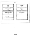
- FIG. 1 is a block diagram of an exemplary system 100 for tracking changes to a volume.
- volume generally refers to any type or form of physical, logical, or virtualized volume of a computing system.
- exemplary system 100 may comprise one or more modules 102 for performing one or more tasks.
- exemplary system 100 may comprise a snapshot-identification module 104 for identifying snapshots of a volume (which, in some situations, may be created by a third-party snapshot provider).
- Exemplary system 100 may also comprise a change-tracking module 106 for tracking changes to a volume, as will be explained in greater detail below.
- exemplary system 100 may comprise a backup-creation module 108 for creating a backup of a computing system (in some cases, based on third-party snapshots).
- the term "backup,” as used herein, may refer to any type or form of backup of at least a portion of a file, a program, or volume of a computing system.
- the term “snapshot,” as used herein, generally refers to a point-in-time copy of data.
- a snapshot may serve as a guide for creating a backup of a computing device.
- exemplary system 100 may also comprise one or more databases 120.
- exemplary system 100 may comprise a change-list database 122 for storing lists that identify changes made to a volume ("change lists").
- exemplary system 100 may also comprise a backups database 123 for storing backups for one or more computing systems.
- databases 120 in FIG. 1 may represent portions of a single database or a single computing device.
- one or more of modules 102 may represent one or more software applications or programs that, when executed by a computing device, may cause the computing device to perform one or more tasks required to track changes made to a volume.
- one or more of modules 102 may represent software modules configured to run on one or more computing devices, such as the computing devices illustrated in FIG. 2 (e.g ., client 202, server 206, and storage devices 208(1) ⁇ (N)), FIG. 3 ( e.g., virtual-machine server 302, virtual-machine client 304, virtual volume 305, storage device 308, and proxy server 310), and FIG. 7 ( e.g ., computing system 710).
- One or more of modules 102 may also represent all or a portion of one or more special-purpose computers configured to perform one or more tasks required to track changes to a volume.
- one or more of databases 120 in FIG. 1 may represent a portion of one or more computing devices.
- one or more of databases 120 may represent a portion of the exemplary computing systems illustrated in FIGS. 2 , 3 , and 7 .
- one or more of databases 120 may represent one or more physically separate devices capable of being accessed by a computing device, such as the exemplary computing devices illustrated in FIGS. 2 , 3 , and 7 .
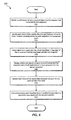
- FIG. 4 is a flow diagram of an exemplary computer-implemented method 400 for tracking changes to a volume.
- a first snapshot of a volume may be identified.
- snapshot-identification module 104 in FIG. 1 may determine that a third-party snapshot provider has created a snapshot.
- the system may identify a window within which the first snapshot identified in step 402 was created.
- this window may begin with a first point known to have occurred before the first snapshot identified in step 402 was created (i.e., a point in time that definitely occurred before creation of the first snapshot) and end with a second point known to have occurred after the first snapshot was created ( i.e ., a point in time that definitely occurred after creation of the first snapshot).
- FIG. 5 is an illustration of a timing diagram for identifying a window within which a snapshot of a volume was created.
- a first snapshot window 512 for a first snapshot 504 may be identified by identifying a first point A1 known to have occurred before the creation of first snapshot 504 and a second point B1 known to have occurred after the creation of first snapshot 504.
- the system may identify at least one change to the volume that occurred within the window.
- change-tracking module 106 may identify each block of the volume that changed within first snapshot window 512 in FIG. 5 .
- the term "block" may refer to the lowest level of addressable space in a volume.
- the blocks identified by change-tracking module 106 may be sectors, files, portions of files, clusters, portions of clusters, or the like of a volume that changed within the window.
- the system may associate the change identified in 406 with both the first snapshot and a second snapshot created after the first snapshot
- change-tracking module 106 in FIG. 1 may associate all changes that occurred within first snapshot window 512 in FIG. 5 with both first snapshot 504 and second snapshot 506.
- such an association may represent a logical association only since the snapshots (which may be provided by a third-party snapshot provider) may have no way of knowing about such an association.
- Step 408 in FIG. 4 may be performed in a variety of ways.
- step 408 may comprise adding a reference to each block of the volume that changed within the window identified in step 404 to both the first snapshot and the second snapshot.
- step 408 may comprise adding a reference to each block of the volume that changed within the window identified in step 404 to both a first change list associated with the first snapshot and a second change list associated with the second snapshot.
- change-tracking module 106 may add a reference to each block of the volume that changed within first snapshot window 512 to both first change list 508 associated with first snapshot 504 and second change list 510 associated with second snapshot 506.
- change lists may identify changes to a volume in a variety of ways.
- a change list may represent a sorted list of indices for blocks in a volume that have changed.
- a change list may represent a bitmap that comprises one bit for each block in a volume. Initially, all bits in the bitmap may be logical zeros (0). However, when a change to a block is identified, a bit corresponding to each changed block may be set to a logical one (1).
- change lists 508 and 510 may identify blocks on a volume that have changed since a prior snapshot.
- change lists 508 and 510 may be used to create an incremental backup of a volume.
- FIG. 6 is a flow diagram of an exemplary computer-implemented method 600 for creating change lists for a volume.
- step 602 may begin upon completion of step 408 in FIG. 4 .
- the system may identify a point known to have occurred before a prior snapshot that preceded a first snapshot was created (i.e. , a point in time that definitely occurred before creation of the prior snapshot).
- change-tracking module 106 in FIG. 1 may identify a point A0 in FIG. 5 known to have occurred before a prior snapshot 502, which was created before first snapshot 504.
- the system may identify each block of a volume that changed between point A0 (i.e., the point known to have occurred before prior snapshot 502 in FIG. 5 ) and point B1 ( i.e ., a point known to have occurred after first snapshot 504).
- the system may add a reference to each block of the volume that changed between point A0 and point B1 to first change list 508 associated with first snapshot 504.
- the system may identify a third point known to have occurred before first snapshot 504 and a fourth point known to have occurred after second snapshot 506 (i.e ., a point in time that definitely occurred after creation of second snapshot 506).
- change-tracking module 106 in FIG. 1 may identify a point A1 as the third point known to have occurred prior to first snapshot 504 and B2 as the fourth point known to have occurred after second snapshot 506 in FIG. 5 .
- the system may identify each block of the volume that changed between point A1 and point B2 in FIG. 5 .
- a reference to each block of the volume that changed between point A1 and point B2 may be added to a second change list 510 associated with second snapshot 506.
- change lists 508 and 510 may be used to create an incremental snapshot or backup of a volume.
- the exemplary systems and methods described herein may enable a backup program to support third-party snapshots, even if the backup program is unable to identify the exact point when a third-party snapshot is created.
- the exemplary systems and methods described herein may enable developers of a software-based backup program to utilize and support snapshots provided by hardware-based and off-host snapshot providers in order to take advantage of the performance benefits offered by hardware-based and off-host snapshots.
- the window within which a third-party snapshot is created may be reduced to a very small period of time. As such, the number of blocks on a volume that change within this window may be relatively small. Regardless, even if blocks that did not actually change since the prior snapshot are unnecessarily added to an incremental backup, these additional blocks in no way affect the validity of the resulting backup, since each block of the volume that changed since the most-recent snapshot is still included in the backup.
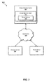
- exemplary system 100 in FIG. 1 may represent portions of a networked system, such as exemplary networked system 200 in FIG. 2 , capable of creating hardware-based snapshots.
- exemplary system 200 may comprise a client 202 in communication with a server 206 and a proxy server 207 via a network 204.
- Client 202 generally represents any type or form of client-side computing device capable of executing computer-readable instructions.
- client 202 may comprise a volume 203.
- Volume 203 generally represents any type or form of storage device or medium capable of storing data and/or computer-readable instructions. Examples of volume 203 include, without limitation, physical volumes, logical volumes, and virtual volumes.
- client 202 may comprise one or more portions of exemplary system 100 in FIG. 1 .
- one or more of modules 102 in FIG. 1 may be stored and configured to run on client 202.
- one or more of databases 120 in FIG. 1 may represent portions of client 202 in FIG. 2 .
- client 202 may communicate with server 206 and proxy server 207 via network 204.
- Network 204 generally represents any type or form of communication or computing network; including, for example, an intranet, a wide area network (WAN), a local area network (LAN), a personal area network (PAN), or the Internet.
- WAN wide area network
- LAN local area network
- PAN personal area network
- Server 206 generally represents any type or form of server-side computing device.
- server 206 may represent a SAN device configured to create and store hardware snapshots of volume 203 of client 202.
- server 206 may comprise one or more portions of exemplary system 100 in FIG. 1 .
- one or more of modules 102 in FIG. 1 may be stored and configured to run on server 206.
- server 206 may comprise one or more of databases 120 in FIG. 1 .
- Proxy server 207 generally represents any type or form of server-side computing device.
- proxy server 207 may access hardware snapshots of volume 203 created by and stored on server 206.
- proxy server 207 may create backups of volume 203 based on the hardware snapshots of volume 203 provided by server 206.
- exemplary system 200 may also comprise one or more storage devices 208(1)-(N).
- Storage devices 208(1)-(N) generally represent any type or form of storage device or medium capable of storing data and/or other computer-readable instructions.
- storage devices 208(1)-(N) may store snapshots or backups of a volume of a computing system, such as volume 203 of client 202.
- snapshot-identification module 104 in FIG. 1 may identify a first hardware snapshot of volume 203 in FIG. 2 .
- this first hardware snapshot of volume 203 may be stored on storage devices 208(1)-(N).
- change-tracking module 106 in FIG. 1 may identify a window within which the first hardware snapshot of volume 203 (identified in step 402) was created. For example, change-tracking module 106 may identify a first point known to have occurred before the first hardware snapshot identified in step 402 was created (i.e., a point in time that definitely occurred before creation of the first hardware snapshot) and a second point known to have occurred after the first hardware snapshot was created ( i.e ., a point in time that definitely occurred after creation of the first hardware snapshot).
- change-tracking module 106 in FIG. 1 may identify at least one change to volume 203 in FIG. 2 by identifying each block of volume 203 that changed within the window identified in step 404.
- change-tracking module 106 in FIG. 1 may add a reference to each block of volume 203 in FIG. 2 that changed within the window to both a first change list associated with the first hardware snapshot and a second change list associated with a second hardware snapshot created after the first hardware snapshot.
- backup-creation module 108 in FIG. 1 may create, using these first and second change lists, incremental backups of volume 203.
- exemplary system 100 in FIG. 1 may represent portions of a virtual environment, such as exemplary virtual environment 300 in FIG. 3 , capable of creating off-host snapshots.
- virtual environment 300 may comprise a virtual-machine server 302, virtual-machine client 304.
- SAN fabric 306. a storage device 308, and a proxy server 310.
- Virtual-machine server 302 generally represents any type or form of device capable of serving or providing access to one or more virtual-machine clients, such as virtual-machine client 304.
- virtual-machine server 302 may represent a single server partitioned into multiple virtual machines by abstracting processor, memory, storage, and networking resources. Examples of virtual-machine server 302 include, without limitation, VMWARE ESX, MICROSOFT HYPERV, or the like.
- virtual-machine server 302 may comprise at least one virtual-machine client 304.
- Virtual-machine client 304 generally represents any type or form of virtual-machine environment.
- virtual-machine client 304 may comprise a virtual volume 305.
- Volume 305 generally represents any type or form of virtual storage for storing data and/or computer-readable instructions. Examples of virtual volume 305 include, without limitation, logical volumes and virtual volumes.
- SAN fabric 306 generally represents any type or form of computer network or architecture capable of facilitating communication between a plurality of storage devices. In the example illustrated in FIG. 3 . SAN fabric 306 may facilitate communication between virtual-machine server 302, storage device 308, and/or proxy server 310. In one example, SAN fabric 306 may enable virtual-machine server 302 and proxy server 310 to mount and access storage device 308.
- storage device 308 generally represents any type or form of storage device or medium capable of storing data and/or computer-readable instructions.
- storage device 308 may store virtual volume 305 of virtual-machine client 304.
- Proxy server 310 in FIG. 3 generally represents any type or form of proxy server capable of accessing the snapshot maintained on the storage device 308 by virtual-machine server 302.
- An example of proxy server 310 includes, without limitation, VMWARE's VIRTUAL CONSOLIDATED BACKUP (VCB).
- one or more of modules 102 from FIG. 1 may be stored and configured to run on one or more portions of virtual environment 300.
- one or more of modules 102 may be stored and configured to run on virtual-machine server 302, virtual-machine client 304, storage device 308, and/or proxy server 310.
- virtual-machine server 302, virtual-machine client 304, virtual volume 305, storage device 308, and/or proxy server 310 may comprise one or more of databases 120 in FIG. 1 .
- modules 102 may enable a software-based backup program to support off-host incremental backups (i.e ., backups created on a different computing system than the one being backed up via snapshots created of a volume on the machine being backed up and accessible to the machine performing the backup).
- off-host incremental backups i.e ., backups created on a different computing system than the one being backed up via snapshots created of a volume on the machine being backed up and accessible to the machine performing the backup.
- snapshot-identification module 104 in FIG. 1 may identify a first off-host snapshot of virtual volume 305 of virtual-machine client 304 in FIG. 3 stored on storage device 308.
- change-tracking module 106 in FIG. 1 may identify a window within which the first off-host snapshot of virtual volume 305 of virtual-machine client 304 (identified in step 402) was created. For example, change-tracking module 106 may identify a first point known to have occurred before the first off-host snapshot identified in step 402 was created (i.e., a point in time that definitely occurred before creation of the first off-host snapshot) and a second point known to have occurred after the first off-host snapshot was created ( i.e ., a point in time that definitely occurred after creation of the first off-host snapshot).
- This window may be identified in a variety of ways.
- change-tracking module 106 may identify this window by monitoring communications in the driver stack on virtual-machine client 304 and/or by utilizing pre- and post-snapshot scripts utilized by virtual-machine client 304 to quiesce data, as known in the art.
- change-tracking module 106 in FIG. 1 may identify each change to virtual volume 305 of virtual-machine client 304 in FIG. 3 that occurred within the window identified in step 404.
- change-tracking module 106 in FIG. 1 may add a reference to each change that occurred to virtual volume 305 of virtual-machine client 304 within the window to both a first change list associated with the first off-host snapshot and a second change list associated with a second off-host snapshot created after the first off-host snapshot.
- these lists may be sent to proxy server 310 using pre- and post-snapshot scripts utilized by virtual-machine client 304.
- backup-creation module 108 in FIG. 1 may create, using these first and second change lists, incremental backups of virtual volume 305 of virtual-machine client 304.
- FIG. 7 is a block diagram of an exemplary computing system 710 capable of implementing one or more of the embodiments described and/or illustrated herein.
- Computing system 710 broadly represents any single or multi-processor computing device or system capable of executing computer-readable instructions. Examples of computing system 710 include, without limitation, workstations, laptops, client-side terminals, servers, distributed computing systems, handheld devices, or any other computing system or device. In its most basic configuration, computing system 710 may comprise at least one processor 714 and system memory 716.
- Processor 714 generally represents any type or form of processing unit capable of processing data or interpreting and executing instructions.
- processor 714 may receive instructions from a software application or module. These instructions may cause processor 714 to perform the functions of one or more of the exemplary embodiments described and/or illustrated herein.
- processor 714 may perform and/or be a means for performing, either alone or in combination with other elements, one or more of the identifying, associating, adding, and creating steps described herein.
- Processor 714 may also perform and/or be a means for performing any other steps, methods, or processes described and/or illustrated herein.
- System memory 716 generally represents any type or form of volatile or non-volatile storage device or medium capable of storing data and/or other computer-readable instructions. Examples of system memory 716 include, without limitation, random access memory (RAM), read only memory (ROM), flash memory, or any other suitable memory device. Although not required, in certain embodiments computing system 710 may comprise both a volatile memory unit (such as, for example, system memory 716) and a non-volatile storage device (such as, for example, primary storage device 732, as described in detail below).
- volatile memory unit such as, for example, system memory 716
- non-volatile storage device such as, for example, primary storage device 732, as described in detail below.
- exemplary computing system 710 may also comprise one or more components or elements in addition to processor 714 and system memory 716.
- computing system 710 may comprise a memory controller 718, an Input/Output (I/O) controller 720, and a communication interface 722, each of which may be interconnected via a communication infrastructure 712.
- Communication infrastructure 712 generally represents any type or form of infrastructure capable of facilitating communication between one or more components of a computing device. Examples of communication infrastructure 712 include, without limitation, a communication bus (such as an ISA, PCI, PCIe, or similar bus) and a network.
- Memory controller 718 generally represents any type or form of device capable of handling memory or data or controlling communication between one or more components of computing system 710. For example, in certain embodiments memory controller 718 may control communication between processor 714, system memory 716, and I/O controller 720 via communication infrastructure 712. In certain embodiments, memory controller 718 may perform and/or be a means for performing, either alone or in combination with other elements, one or more of the steps or features described and/or illustrated herein, such as identifying, associating, adding, and/or creating.
- I/O controller 720 generally represents any type or form of module capable of coordinating and/or controlling the input and output functions of a computing device.
- I/O controller 720 may control or facilitate transfer of data between one or more elements of computing system 710, such as processor 714, system memory 716, communication interface 722, display adapter 726, input interface 730, and storage interface 734.
- I/O controller 720 may be used, for example, to perform and/or be a means for performing the identifying, associating, adding, and creating steps described herein.
- I/O controller 720 may also be used to perform and/or be a means for performing other steps and features set forth in the instant disclosure.
- Communication interface 722 broadly represents any type or form of communication device or adapter capable of facilitating communication between exemplary computing system 710 and one or more additional devices.
- communication interface 722 may facilitate communication between computing system 710 and a private or public network comprising additional computing systems.
- Examples of communication interface 722 include, without limitation, a wired network interface (such as a network interface card), a wireless network interface (such as a wireless network interface card), a modem, and any other suitable interface.
- communication interface 722 may provide a direct connection to a remote server via a direct link to a network, such as the Internet.
- Communicating interface 722 may also indirectly provide such a connection through for example, a local area network (such as an Ethernet network or a wireless IEEE 802.11 network), a personal area network (such as a BLUETOOTH or IEEE 802.15 network), a telephone or cable network, a cellular telephone connection, a satellite data connection, or any other suitable connection.
- a local area network such as an Ethernet network or a wireless IEEE 802.11 network
- a personal area network such as a BLUETOOTH or IEEE 802.15 network
- a telephone or cable network such as a cellular telephone connection, a satellite data connection, or any other suitable connection.
- communication interface 722 may also represent a host adapter configured to facilitate communication between computing system 710 and one or more additional network or storage devices via an external bus or communications channel.
- host adapters include, without limitation, SCSI host adapters, USB host adapters, IEEE 1394 host adapters, SATA and eSATA host adapters, ATA and PATA host adapters, Fibre Channel interface adapters, Ethernet adapters, or the like.
- Communication interface 722 may also allow computing system 710 to engage in distributed or remote computing. For example, communication interface 722 may receive instructions from a remote device or send instructions to a remote device for execution.
- communication interface 722 may perform and/or be a means for performing, either alone or in combination with other elements, one or more of the identifying, associating, adding, and creating steps disclosed herein. Communication interface 722 may also be used to perform and/or be a means for performing other steps and features set forth in the instant disclosure.
- computing system 710 may also comprise at least one display device 724 coupled to communication infrastructure 712 via a display adapter 726.
- Display device 724 generally represents any type or form of device capable of visually displaying information forwarded by display adapter 726.
- display adapter 726 generally represents any type or form of device configured to forward graphics, text, and other data from communication infrastructure 712 (or from a frame buffer, as known in the art) for display on display device 724.
- exemplary computing system 710 may also comprise at least one input device 728 coupled to communication infrastructure 712 via an input interface 730.
- Input device 728 generally represents any type or form of input device capable of providing input, either computer or human generated, to exemplary computing system 710. Examples of input device 728 include, without limitation, a keyboard, a pointing device, a speech recognition device, or any other input device.
- input device 728 may perform and/or be a means for performing, either alone or in combination with other elements, one or more of the identifying, associating, adding, and creating steps disclosed herein.
- Input device 728 may also be used to perform and/or be a means for performing other steps and features set forth in the instant disclosure.
- exemplary computing system 710 may also comprise a primary storage device 732 and a backup storage device 733 coupled to communication infrastructure 712 via a storage interface 734.
- Storage devices 732 and 733 generally represent any type or form of storage device or medium capable of storing data and/or other computer-readable instructions.
- storage devices 732 and 733 may be a magnetic disk drive (e.g. , a so-called hard drive), a floppy disk drive, a magnetic tape drive, an optical disk drive, a flash drive, or the like.
- Storage interface 734 generally represents any type or form of interface or device for transferring data between storage devices 732 and 733 and other components of computing system 710.
- storage devices 732 and 733 may be configured to read from and/or write to a removable storage unit configured to store computer software, data, or other computer-readable information.
- suitable removable storage units include, without limitation, a floppy disk, a magnetic tape, an optical disk, a flash memory device, or the like.
- Storage devices 732 and 733 may also comprise other similar structures or devices for allowing computer software, data, or other computer-readable instructions to be loaded into computing system 710.
- storage devices 732 and 733 may be configured to read and write software, data, or other computer-readable information.
- Storage devices 732 and 733 may also be a part of computing system 710 or may be a separate device accessed through other interface systems.
- Storage devices 732 and 733 may also be used, for example, to perform and/or be a means for performing, either alone or in combination with other elements, one or more of the identifying, associating, adding, and creating steps disclosed herein. Storage devices 732 and 733 may also be used to perform and/or be a means for performing other steps and features set forth in the instant disclosure.
- computing system 710 may also employ any number of software, firmware, and/or hardware configurations.
- one or more of the exemplary embodiments disclosed herein may be encoded as a computer program (also referred to as computer software, software applications, computer-readable instructions, or computer control logic) on a computer-readable medium.
- computer program also referred to as computer software, software applications, computer-readable instructions, or computer control logic
- computer-readable medium generally refers to any form of device, carrier, or medium capable of storing or carrying computer-readable instructions.
- Examples of computer-readable media include, without limitation, transmission-type media, such as carrier waves, and physical media, such as magnetic-storage media (e.g., hard disk drives and floppy disks), optical-storage media (e.g., CD- or DVD-ROMs), electronic-storage media (e.g., solid-state drives and flash media), and other distribution systems.
- transmission-type media such as carrier waves
- physical media such as magnetic-storage media (e.g., hard disk drives and floppy disks), optical-storage media (e.g., CD- or DVD-ROMs), electronic-storage media (e.g., solid-state drives and flash media), and other distribution systems.
- the computer-readable medium containing the computer program may be loaded into computing system 710. All or a portion of the computer program stored on the computer-readable medium may then be stored in system memory 716 and/or various portions of storage devices 732 and 733.
- a computer program loaded into computing system 710 may cause processor 714 to perform and/or be a means for performing the functions of one or more of the exemplary embodiments described and/or illustrated herein.
- one or more of the exemplary embodiments described and/or illustrated herein may be implemented in firmware and/or hardware.
- computing system 710 may be configured as an application specific integrated circuit (ASIC) adapted to implement one or more of the exemplary embodiments disclosed herein.
- ASIC application specific integrated circuit
- computing system 710 may perform and/or be a means for performing, either alone or in combination with other elements, one or more steps of the exemplary methods described and/or illustrated herein.
- a computer-implemented method for tracking changes made to a volume may comprise identifying a first snapshot of the volume.
- the first snapshot may comprise a software and/or a hardware snapshot.
- the method may also comprise identifying a window within which the first snapshot was created. The window may begin with a first point known to have occurred before the first snapshot and end with a second point known to have occurred after the first snapshot.
- the method may further comprise identifying at least one change to the volume that occurred within the window and associating such changes that occurred within the window with both the first snapshot and a second snapshot.
- the second snapshot may be created after the first snapshot.
- identifying at least one change to the volume may comprise identifying each block of the volume that changed within the window.
- the method may further comprises 1) identifying a point known to have occurred before a prior snapshot that preceded the first snapshot, 2) identifying each block of the volume that changed between the point known to have occurred before the prior snapshot and the second point, and then 3) adding a reference to each block of the volume that changed between the point known to have occurred before the prior snapshot and the second point to a first list associated with the first snapshot.
- a full backup of the volume may then be created.
- a first incremental backup of the volume may be created using the first list.
- the method may further comprise identifying a third point known to have occurred after the second snapshot and identifying each block of the volume that changed between the first and third points.
- a reference to each block of the volume that changed between the first and third points may then be added to a second list associated with the second snapshot.
- the mentioned process of adding references to changed blocks to corresponding lists may comprise creating the first and second lists.
- the method may comprise adding a reference to each block of the volume that changed within the window to both the first and second lists.
- a first incremental backup of the volume may be created using the first list.
- a second incremental backup of the volume may be created using the second list.
- a system for tracking changes to a volume in a networked environment may comprise at least one client comprising at least one volume.
- a server may communicate with the client.
- the server may also comprise a change-tracking module configured to identify a window within which a first snapshot of the volume was created. The window may begin with a first point known to have occurred before the first snapshot and end with a second point known to have occurred after the first snapshot.
- the change-tracking module may also be configured to identify at least one change to the volume that occurred within the window and associate the at least one change that occurred within the window with both the first snapshot and a second snapshot.
- the second snapshot may be created after the first snapshot.
- the change-tracking module may be configured to identify a point known to have occurred before a prior snapshot that preceded the first snapshot.
- the change-tracking module may also be configured to identify each block of the volume that changed between the point known to have occurred before the prior snapshot and the second point.
- the change-tracking module may be further configured to add a reference to each block of the volume that changed between the point known to have occurred before the prior snapshot and the second point to a first list.
- the first list may be associated with the first snapshot.
- the change-tracking module may be configured to identify a third point known to have occurred after the second snapshot.
- the change-tracking module may be further configured to identify each block of the volume that changed between the first and third points.
- a reference to each block of the volume that changed between the first and third points may be added to a second list.
- the second list may be associated with the second snapshot.
- the change-tracking module may associate the at least one change that occurred within the window with both the first and second snapshots. Said association may comprise adding a reference to each block of the volume that changed within the window to both the first and second lists.
- the change-tracking module may comprise a backup-creation module.
- the backup-creation module may be configured to create a full backup of the volume using the prior snapshot.
- the backup-creation module may also be configured to create a first incremental backup of the volume using the first list and/or the first snapshot.
- a system for tracking changes to a volume in a virtual environment may comprise a virtual-machine server comprising at least one virtual-machine client.
- the system may also comprise a storage area network in communication with the virtual-machine server.
- the system may comprise a change-tracking module configured to identify a window within which a first snapshot of the virtual-machine client was created. Said window may begin with a first point known to have occurred before the first snapshot and end with a second point known to have occurred after the first snapshot.
- the change-tracking module may be further configured to identify at least one change to the virtual-machine client that occurred within the window and associate the at least one change with both the first and second snapshots.
- the second snapshot may be created after the first snapshot.
- the change-tracking module may be configured to: 1) identify a point that occurred before a prior snapshot that preceded the first snapshot, 2) identify each change to the virtual-machine client that occurred between the point known to have occurred before the prior snapshot and the second point, and 3) add references to said changes to a first list associated with the first snapshot.
- the change-tracking module may comprise a proxy server in communication with the storage network.
- the proxy server in communication with the storage network may further comprise a backup-creation module.
- the backup-creation module may be configured to create a full backup of the virtual-machine client using the prior snapshot.
- the backup-creation module may be further configured to create a first incremental backup of the virtual-machine client using the first list.
- the change-tracking module may be configured to identify a third point known to have occurred after the second snapshot.
- the change-tracking module may also be configured to identify each change to the virtual-machine client that occurred between the first and third points.
- a reference to each change to the virtual-machine client that occurred between the first and third points may be added to a second list associated with the second snapshot.
- the change-tracking module may associate the at least one change that occurred within the window with both the first and second snapshots. Said association may comprise adding a reference to each change that occurred to the virtual-machine client within the window to both the first and second lists.
Landscapes
- Engineering & Computer Science (AREA)
- Theoretical Computer Science (AREA)
- Quality & Reliability (AREA)
- Physics & Mathematics (AREA)
- General Engineering & Computer Science (AREA)
- General Physics & Mathematics (AREA)
- Information Retrieval, Db Structures And Fs Structures Therefor (AREA)
Claims (15)
- Procédé mis en oeuvre sur un ordinateur pour suivre des changements apportés à un volume, le procédé comprenant :l'identification (402) d'un premier instantané du volume ;l'identification d'une fenêtre (404) au sein de laquelle le premier instantané (504) a été créé, la fenêtre (512) commençant par un premier point (A1) connu pour s'être produit avant le premier instantané et se terminant par un deuxième point (D1) connu pour s'être produit après le premier instantané ;l'identification (406) d'au moins un changement au volume qui s'est produit au sein de la fenêtre ;l'association (408) de l'au moins un changement qui s'est produit au sein de la fenêtre à la fois au premier instantané et à un deuxième instantané (506) créé après le premier instantané.
- Procédé selon la revendication 1, dans lequel l'identification de l'au moins un changement au volume comprend l'identification de chaque bloc du volume qui a changé au sein de la fenêtre.
- Procédé selon la revendication 2, comprenant en outre :l'identification d'un point connu pour s'être produit avant un instantané préalable qui a précédé le premier instantané ;l'identification de chaque bloc du volume qui a changé entre le point connu pour s'être produit avant l'instantané préalable et le deuxième point ;l'ajout d'une référence à chaque bloc du volume qui a changé entre le point connu pour s'être produit avant l'instantané préalable et le deuxième point à une première liste associée au premier instantané.
- Procédé selon la revendication 3, comprenant en outre :la création, en utilisant l'instantané préalable, d'une sauvegarde complète du volume ;la création, en utilisant au moins un parmi la première liste et le premier instantané, d'une première sauvegarde incrémentielle du volume.
- Procédé selon la revendication 3, comprenant en outre :l'identification d'un troisième point connu pour s'être produit après le deuxième instantané ;l'identification de chaque bloc du volume qui a changé entre le premier point et le troisième point ;l'ajout d'une référence à chaque bloc du volume qui a changé entre le premier point et le troisième point à une deuxième liste associée au deuxième instantané.
- Procédé selon la revendication 5, dans lequel l'association de l'au moins un changement qui s'est produit au sein de la fenêtre à la fois au premier instantané et au deuxième instantané comprend l'ajout d'une référence à chaque bloc du volume qui a changé au sein de la fenêtre à la fois à la première liste et à la deuxième liste.
- Procédé selon la revendication 5, comprenant en outre :la création de la première liste ;la création de la deuxième liste ;
- Procédé selon la revendication 5, comprenant en outre :la création, en utilisant au moins un parmi la première liste et le premier instantané, d'une première sauvegarde incrémentielle du volume ;la création, en utilisant au moins un parmi la deuxième liste et le deuxième instantané, d'une deuxième sauvegarde incrémentielle du volume.
- Procédé selon la revendication 1, dans lequel le premier instantané comprend :un instantané logiciel ;un instantané matériel.
- Système pour suivre des changements à un volume dans un environnement en réseau, le système comprenant :au moins un client comprenant au moins un volume ;un serveur en communication avec le client ;un moyen de suivi de changements sur le serveur, le moyen de suivi de changements configuré pour :identifier une fenêtre au sein de laquelle un premier instantané du volume a été créé, la fenêtre commençant par un premier point connu pour s'être produit avant le premier instantané et se terminant par un deuxième point connu pour s'être produit après le premier instantané ;identifier au moins un changement au volume qui s'est produit au sein de la fenêtre ;associer l'au moins un changement qui s'est produit au sein de la fenêtre à la fois au premier instantané et à un deuxième instantané créé après le premier instantané.
- Système selon la revendication 10, dans lequel le moyen de suivi de changements est en outre configuré pour :identifier un point connu pour s'être produit avant un instantané préalable qui a précédé le premier instantané ;identifier chaque bloc du volume qui a changé entre le point connu pour s'être produit avant l'instantané préalable et le deuxième point ;ajouter une référence à chaque bloc du volume qui a changé entre le point connu pour s'être produit avant l'instantané de base et le deuxième point à une première liste associée au premier instantané.
- Système selon la revendication 11, comprenant en outre un moyen de création de sauvegarde configuré pour :créer, en utilisant l'instantané préalable, une sauvegarde complète du volume ;créer, en utilisant au moins un parmi la première liste et le premier instantané, une première sauvegarde incrémentielle du volume.
- Système selon la revendication 11, dans lequel le moyen de suivi de changements est en outre configuré pour :identifier un troisième point connu pour s'être produit après le deuxième instantané ;identifier chaque bloc du volume qui a changé entre le premier point et le troisième point ;ajouter une référence à chaque bloc du volume qui a changé entre le premier point et le troisième point à une deuxième liste associée au deuxième instantané.
- Système selon la revendication 13, dans lequel le moyen de suivi de changements associe l'au moins un changement qui s'est produit au sein de la fenêtre à la fois au premier instantané et au deuxième instantané en ajoutant une référence à chaque bloc du volume qui a changé au sein de la fenêtre à la fois à la première liste et à la deuxième liste.
- Système selon la revendication 13, comprenant en outre un moyen de création de sauvegarde configuré pour :créer, en utilisant au moins un parmi la première liste et le premier instantané, une première sauvegarde incrémentielle du volume ;créer, en utilisant au moins un parmi la deuxième liste et le deuxième instantané, une deuxième sauvegarde incrémentielle du volume.
Applications Claiming Priority (2)
| Application Number | Priority Date | Filing Date | Title |
|---|---|---|---|
| US12/164,458 US8065272B2 (en) | 2008-05-30 | 2008-06-30 | Systems and methods for tracking changes to a volume |
| PCT/US2009/047494 WO2010002582A1 (fr) | 2008-06-30 | 2009-06-16 | Systèmes et procédés de suivi de changements apportés à un volume |
Publications (2)
| Publication Number | Publication Date |
|---|---|
| EP2318927A1 EP2318927A1 (fr) | 2011-05-11 |
| EP2318927B1 true EP2318927B1 (fr) | 2015-02-25 |
Family
ID=40975428
Family Applications (1)
| Application Number | Title | Priority Date | Filing Date |
|---|---|---|---|
| EP09774034.4A Active EP2318927B1 (fr) | 2008-06-30 | 2009-06-16 | Systèmes et procédés de suivi de changements apportés à un volume |
Country Status (5)
| Country | Link |
|---|---|
| US (1) | US8065272B2 (fr) |
| EP (1) | EP2318927B1 (fr) |
| JP (1) | JP5547727B2 (fr) |
| CN (1) | CN102057358B (fr) |
| WO (1) | WO2010002582A1 (fr) |
Families Citing this family (14)
| Publication number | Priority date | Publication date | Assignee | Title |
|---|---|---|---|---|
| US8499297B2 (en) * | 2008-10-28 | 2013-07-30 | Vmware, Inc. | Low overhead fault tolerance through hybrid checkpointing and replay |
| US8538919B1 (en) | 2009-05-16 | 2013-09-17 | Eric H. Nielsen | System, method, and computer program for real time remote recovery of virtual computing machines |
| US9535907B1 (en) * | 2010-01-22 | 2017-01-03 | Veritas Technologies Llc | System and method for managing backup operations of virtual machines |
| US8886609B2 (en) * | 2010-12-17 | 2014-11-11 | Microsoft Corporation | Backup and restore of data from any cluster node |
| US9128943B1 (en) * | 2011-09-29 | 2015-09-08 | Emc Corporation | Method and system for tracking re-sizing and re-creation of volumes created for making incremental backups |
| US9098452B2 (en) * | 2011-12-19 | 2015-08-04 | International Business Machines Corporation | Selecting files to backup in a block level backup |
| US9378096B1 (en) * | 2012-06-30 | 2016-06-28 | Emc Corporation | System and method for cache management |
| US9430164B1 (en) * | 2013-02-08 | 2016-08-30 | Emc Corporation | Memory efficient sanitization of a deduplicated storage system |
| US9317218B1 (en) | 2013-02-08 | 2016-04-19 | Emc Corporation | Memory efficient sanitization of a deduplicated storage system using a perfect hash function |
| US10614047B1 (en) | 2013-09-24 | 2020-04-07 | EMC IP Holding Company LLC | Proxy-based backup and restore of hyper-V cluster shared volumes (CSV) |
| US10628200B2 (en) | 2017-11-02 | 2020-04-21 | Red Hat Israel, Ltd. | Base state for thin-provisioned volumes |
| US10936428B2 (en) * | 2019-01-22 | 2021-03-02 | EMC IP Holding Company LLC | System and method to implement automated application consistent virtual machine image backup |
| US11886298B2 (en) * | 2021-03-31 | 2024-01-30 | Cohesity, Inc. | Using a storage log to generate an incremental backup |
| US11954066B2 (en) | 2021-07-21 | 2024-04-09 | Cohesity, Inc. | Coalescing storage log entries |
Family Cites Families (15)
| Publication number | Priority date | Publication date | Assignee | Title |
|---|---|---|---|---|
| JPH0798634A (ja) * | 1993-09-29 | 1995-04-11 | Hitachi Ltd | 磁気テープ媒体の切替え方式 |
| US5835953A (en) * | 1994-10-13 | 1998-11-10 | Vinca Corporation | Backup system that takes a snapshot of the locations in a mass storage device that has been identified for updating prior to updating |
| JP3856855B2 (ja) | 1995-10-06 | 2006-12-13 | 三菱電機株式会社 | 差分バックアップ方式 |
| US6269381B1 (en) * | 1998-06-30 | 2001-07-31 | Emc Corporation | Method and apparatus for backing up data before updating the data and for restoring from the backups |
| US7296125B2 (en) * | 2001-11-29 | 2007-11-13 | Emc Corporation | Preserving a snapshot of selected data of a mass storage system |
| CA2508089A1 (fr) * | 2002-10-07 | 2004-04-22 | Commvault Systems, Inc. | Systeme et procede de gestion de donnees stockees |
| US8037264B2 (en) * | 2003-01-21 | 2011-10-11 | Dell Products, L.P. | Distributed snapshot process |
| US7343518B2 (en) | 2004-06-23 | 2008-03-11 | Intel Corporation | Method for data backup of computing platforms that are occasionally connected |
| EP1782210A4 (fr) * | 2004-07-23 | 2012-02-01 | Emc Corp | Suivi d'objets modifies entre des operations de sauvegarde informatique |
| US7284150B2 (en) | 2004-09-22 | 2007-10-16 | International Business Machines Corporation | System and method for reliably storing data and providing efficient incremental backup and asynchronous mirroring by preferentially handling new data |
| US20060080362A1 (en) * | 2004-10-12 | 2006-04-13 | Lefthand Networks, Inc. | Data Synchronization Over a Computer Network |
| US7716171B2 (en) * | 2005-08-18 | 2010-05-11 | Emc Corporation | Snapshot indexing |
| CN101132446A (zh) * | 2006-08-23 | 2008-02-27 | 上海万纬信息技术有限公司 | 网页智能快照系统及其方法 |
| US20080140963A1 (en) | 2006-12-11 | 2008-06-12 | Thomason Ronald G | Methods and systems for storage system generation and use of differential block lists using copy-on-write snapshots |
| CN101087406B (zh) * | 2007-06-19 | 2012-06-06 | 中兴通讯股份有限公司 | 一种监控系统即时快照的方法和系统 |
-
2008
- 2008-06-30 US US12/164,458 patent/US8065272B2/en active Active
-
2009
- 2009-06-16 WO PCT/US2009/047494 patent/WO2010002582A1/fr active Application Filing
- 2009-06-16 CN CN200980121918.9A patent/CN102057358B/zh active Active
- 2009-06-16 EP EP09774034.4A patent/EP2318927B1/fr active Active
- 2009-06-16 JP JP2011516445A patent/JP5547727B2/ja active Active
Also Published As
| Publication number | Publication date |
|---|---|
| JP2012527656A (ja) | 2012-11-08 |
| CN102057358A (zh) | 2011-05-11 |
| US8065272B2 (en) | 2011-11-22 |
| CN102057358B (zh) | 2013-09-11 |
| US20090300080A1 (en) | 2009-12-03 |
| JP5547727B2 (ja) | 2014-07-16 |
| EP2318927A1 (fr) | 2011-05-11 |
| WO2010002582A1 (fr) | 2010-01-07 |
Similar Documents
| Publication | Publication Date | Title |
|---|---|---|
| EP2318927B1 (fr) | Systèmes et procédés de suivi de changements apportés à un volume | |
| EP2840495B1 (fr) | Procédé et dispositif de traitement basé sur un contenant | |
| US10678663B1 (en) | Synchronizing storage devices outside of disabled write windows | |
| US9424136B1 (en) | Systems and methods for creating optimized synthetic backup images | |
| US9684567B2 (en) | Hypervisor agnostic interchangeable backup recovery and file level recovery from virtual disks | |
| EP3356941B1 (fr) | Systèmes et procédés pour restaurer des données à partir de flux de sauvegarde de données opaques | |
| JP6186374B2 (ja) | 仮想化されたプラットフォームへ安全に移行するためのシステム及び方法 | |
| US9372762B2 (en) | Systems and methods for restoring application data | |
| US9298724B1 (en) | Systems and methods for preserving deduplication efforts after backup-job failures | |
| US8990164B1 (en) | Systems and methods for performing incremental backups | |
| US8117168B1 (en) | Methods and systems for creating and managing backups using virtual disks | |
| CN103810058B (zh) | 虚拟机备份方法、设备及系统 | |
| US9354907B1 (en) | Optimized restore of virtual machine and virtual disk data | |
| US11698808B2 (en) | System and method of selectively restoring a computer system to an operational state | |
| US9524215B1 (en) | Systems and methods for managing virtual machine backups | |
| US8707107B1 (en) | Systems and methods for proactively facilitating restoration of potential data failures | |
| US8595192B1 (en) | Systems and methods for providing high availability to instance-bound databases | |
| US9003139B1 (en) | Systems and methods for recovering virtual machines after disaster scenarios | |
| US9336131B1 (en) | Systems and methods for enabling virtual environments to mount non-native storage disks | |
| US8565545B1 (en) | Systems and methods for restoring images | |
| EP3625683B1 (fr) | Système et méthode pour une sauvegarde de données à charge équilibrée | |
| US9529679B2 (en) | Volume snapshot in a shared environment | |
| US10176055B1 (en) | Systems and methods for generating full backups of applications | |
| US8392373B1 (en) | Systems and methods for retaining an executable environment during a data archive process | |
| US10318386B1 (en) | Systems and methods for maintaining remote backups of reverse-incremental backup datasets |
Legal Events
| Date | Code | Title | Description |
|---|---|---|---|
| PUAI | Public reference made under article 153(3) epc to a published international application that has entered the european phase |
Free format text: ORIGINAL CODE: 0009012 |
|
| 17P | Request for examination filed |
Effective date: 20110124 |
|
| AK | Designated contracting states |
Kind code of ref document: A1 Designated state(s): AT BE BG CH CY CZ DE DK EE ES FI FR GB GR HR HU IE IS IT LI LT LU LV MC MK MT NL NO PL PT RO SE SI SK TR |
|
| AX | Request for extension of the european patent |
Extension state: AL BA RS |
|
| DAX | Request for extension of the european patent (deleted) | ||
| GRAP | Despatch of communication of intention to grant a patent |
Free format text: ORIGINAL CODE: EPIDOSNIGR1 |
|
| INTG | Intention to grant announced |
Effective date: 20140919 |
|
| GRAS | Grant fee paid |
Free format text: ORIGINAL CODE: EPIDOSNIGR3 |
|
| GRAA | (expected) grant |
Free format text: ORIGINAL CODE: 0009210 |
|
| AK | Designated contracting states |
Kind code of ref document: B1 Designated state(s): AT BE BG CH CY CZ DE DK EE ES FI FR GB GR HR HU IE IS IT LI LT LU LV MC MK MT NL NO PL PT RO SE SI SK TR |
|
| REG | Reference to a national code |
Ref country code: GB Ref legal event code: FG4D |
|
| REG | Reference to a national code |
Ref country code: CH Ref legal event code: EP |
|
| REG | Reference to a national code |
Ref country code: IE Ref legal event code: FG4D |
|
| REG | Reference to a national code |
Ref country code: DE Ref legal event code: R096 Ref document number: 602009029602 Country of ref document: DE Effective date: 20150409 |
|
| REG | Reference to a national code |
Ref country code: AT Ref legal event code: REF Ref document number: 712505 Country of ref document: AT Kind code of ref document: T Effective date: 20150415 |
|
| REG | Reference to a national code |
Ref country code: NL Ref legal event code: VDEP Effective date: 20150225 |
|
| REG | Reference to a national code |
Ref country code: AT Ref legal event code: MK05 Ref document number: 712505 Country of ref document: AT Kind code of ref document: T Effective date: 20150225 |
|
| REG | Reference to a national code |
Ref country code: LT Ref legal event code: MG4D |
|
| PG25 | Lapsed in a contracting state [announced via postgrant information from national office to epo] |
Ref country code: NO Free format text: LAPSE BECAUSE OF FAILURE TO SUBMIT A TRANSLATION OF THE DESCRIPTION OR TO PAY THE FEE WITHIN THE PRESCRIBED TIME-LIMIT Effective date: 20150525 Ref country code: SE Free format text: LAPSE BECAUSE OF FAILURE TO SUBMIT A TRANSLATION OF THE DESCRIPTION OR TO PAY THE FEE WITHIN THE PRESCRIBED TIME-LIMIT Effective date: 20150225 Ref country code: LT Free format text: LAPSE BECAUSE OF FAILURE TO SUBMIT A TRANSLATION OF THE DESCRIPTION OR TO PAY THE FEE WITHIN THE PRESCRIBED TIME-LIMIT Effective date: 20150225 Ref country code: ES Free format text: LAPSE BECAUSE OF FAILURE TO SUBMIT A TRANSLATION OF THE DESCRIPTION OR TO PAY THE FEE WITHIN THE PRESCRIBED TIME-LIMIT Effective date: 20150225 Ref country code: HR Free format text: LAPSE BECAUSE OF FAILURE TO SUBMIT A TRANSLATION OF THE DESCRIPTION OR TO PAY THE FEE WITHIN THE PRESCRIBED TIME-LIMIT Effective date: 20150225 Ref country code: FI Free format text: LAPSE BECAUSE OF FAILURE TO SUBMIT A TRANSLATION OF THE DESCRIPTION OR TO PAY THE FEE WITHIN THE PRESCRIBED TIME-LIMIT Effective date: 20150225 |
|
| PG25 | Lapsed in a contracting state [announced via postgrant information from national office to epo] |
Ref country code: LV Free format text: LAPSE BECAUSE OF FAILURE TO SUBMIT A TRANSLATION OF THE DESCRIPTION OR TO PAY THE FEE WITHIN THE PRESCRIBED TIME-LIMIT Effective date: 20150225 Ref country code: AT Free format text: LAPSE BECAUSE OF FAILURE TO SUBMIT A TRANSLATION OF THE DESCRIPTION OR TO PAY THE FEE WITHIN THE PRESCRIBED TIME-LIMIT Effective date: 20150225 Ref country code: IS Free format text: LAPSE BECAUSE OF FAILURE TO SUBMIT A TRANSLATION OF THE DESCRIPTION OR TO PAY THE FEE WITHIN THE PRESCRIBED TIME-LIMIT Effective date: 20150625 Ref country code: GR Free format text: LAPSE BECAUSE OF FAILURE TO SUBMIT A TRANSLATION OF THE DESCRIPTION OR TO PAY THE FEE WITHIN THE PRESCRIBED TIME-LIMIT Effective date: 20150526 |
|
| PG25 | Lapsed in a contracting state [announced via postgrant information from national office to epo] |
Ref country code: NL Free format text: LAPSE BECAUSE OF FAILURE TO SUBMIT A TRANSLATION OF THE DESCRIPTION OR TO PAY THE FEE WITHIN THE PRESCRIBED TIME-LIMIT Effective date: 20150225 |
|
| PG25 | Lapsed in a contracting state [announced via postgrant information from national office to epo] |
Ref country code: RO Free format text: LAPSE BECAUSE OF FAILURE TO SUBMIT A TRANSLATION OF THE DESCRIPTION OR TO PAY THE FEE WITHIN THE PRESCRIBED TIME-LIMIT Effective date: 20150225 Ref country code: SK Free format text: LAPSE BECAUSE OF FAILURE TO SUBMIT A TRANSLATION OF THE DESCRIPTION OR TO PAY THE FEE WITHIN THE PRESCRIBED TIME-LIMIT Effective date: 20150225 Ref country code: CZ Free format text: LAPSE BECAUSE OF FAILURE TO SUBMIT A TRANSLATION OF THE DESCRIPTION OR TO PAY THE FEE WITHIN THE PRESCRIBED TIME-LIMIT Effective date: 20150225 Ref country code: DK Free format text: LAPSE BECAUSE OF FAILURE TO SUBMIT A TRANSLATION OF THE DESCRIPTION OR TO PAY THE FEE WITHIN THE PRESCRIBED TIME-LIMIT Effective date: 20150225 Ref country code: EE Free format text: LAPSE BECAUSE OF FAILURE TO SUBMIT A TRANSLATION OF THE DESCRIPTION OR TO PAY THE FEE WITHIN THE PRESCRIBED TIME-LIMIT Effective date: 20150225 |
|
| REG | Reference to a national code |
Ref country code: DE Ref legal event code: R097 Ref document number: 602009029602 Country of ref document: DE |
|
| PG25 | Lapsed in a contracting state [announced via postgrant information from national office to epo] |
Ref country code: PL Free format text: LAPSE BECAUSE OF FAILURE TO SUBMIT A TRANSLATION OF THE DESCRIPTION OR TO PAY THE FEE WITHIN THE PRESCRIBED TIME-LIMIT Effective date: 20150225 |
|
| PG25 | Lapsed in a contracting state [announced via postgrant information from national office to epo] |
Ref country code: IT Free format text: LAPSE BECAUSE OF FAILURE TO SUBMIT A TRANSLATION OF THE DESCRIPTION OR TO PAY THE FEE WITHIN THE PRESCRIBED TIME-LIMIT Effective date: 20150225 |
|
| PLBE | No opposition filed within time limit |
Free format text: ORIGINAL CODE: 0009261 |
|
| STAA | Information on the status of an ep patent application or granted ep patent |
Free format text: STATUS: NO OPPOSITION FILED WITHIN TIME LIMIT |
|
| PG25 | Lapsed in a contracting state [announced via postgrant information from national office to epo] |
Ref country code: MC Free format text: LAPSE BECAUSE OF FAILURE TO SUBMIT A TRANSLATION OF THE DESCRIPTION OR TO PAY THE FEE WITHIN THE PRESCRIBED TIME-LIMIT Effective date: 20150225 |
|
| REG | Reference to a national code |
Ref country code: CH Ref legal event code: PL |
|
| 26N | No opposition filed |
Effective date: 20151126 |
|
| PG25 | Lapsed in a contracting state [announced via postgrant information from national office to epo] |
Ref country code: LU Free format text: LAPSE BECAUSE OF FAILURE TO SUBMIT A TRANSLATION OF THE DESCRIPTION OR TO PAY THE FEE WITHIN THE PRESCRIBED TIME-LIMIT Effective date: 20150616 Ref country code: SI Free format text: LAPSE BECAUSE OF FAILURE TO SUBMIT A TRANSLATION OF THE DESCRIPTION OR TO PAY THE FEE WITHIN THE PRESCRIBED TIME-LIMIT Effective date: 20150225 |
|
| REG | Reference to a national code |
Ref country code: IE Ref legal event code: MM4A |
|
| PG25 | Lapsed in a contracting state [announced via postgrant information from national office to epo] |
Ref country code: LI Free format text: LAPSE BECAUSE OF NON-PAYMENT OF DUE FEES Effective date: 20150630 Ref country code: CH Free format text: LAPSE BECAUSE OF NON-PAYMENT OF DUE FEES Effective date: 20150630 Ref country code: IE Free format text: LAPSE BECAUSE OF NON-PAYMENT OF DUE FEES Effective date: 20150616 |
|
| REG | Reference to a national code |
Ref country code: FR Ref legal event code: PLFP Year of fee payment: 8 |
|
| PG25 | Lapsed in a contracting state [announced via postgrant information from national office to epo] |
Ref country code: BE Free format text: LAPSE BECAUSE OF FAILURE TO SUBMIT A TRANSLATION OF THE DESCRIPTION OR TO PAY THE FEE WITHIN THE PRESCRIBED TIME-LIMIT Effective date: 20150225 |
|
| PG25 | Lapsed in a contracting state [announced via postgrant information from national office to epo] |
Ref country code: MT Free format text: LAPSE BECAUSE OF FAILURE TO SUBMIT A TRANSLATION OF THE DESCRIPTION OR TO PAY THE FEE WITHIN THE PRESCRIBED TIME-LIMIT Effective date: 20150225 |
|
| REG | Reference to a national code |
Ref country code: GB Ref legal event code: 732E Free format text: REGISTERED BETWEEN 20170316 AND 20170323 |
|
| REG | Reference to a national code |
Ref country code: FR Ref legal event code: PLFP Year of fee payment: 9 |
|
| PG25 | Lapsed in a contracting state [announced via postgrant information from national office to epo] |
Ref country code: HU Free format text: LAPSE BECAUSE OF FAILURE TO SUBMIT A TRANSLATION OF THE DESCRIPTION OR TO PAY THE FEE WITHIN THE PRESCRIBED TIME-LIMIT; INVALID AB INITIO Effective date: 20090616 Ref country code: BG Free format text: LAPSE BECAUSE OF FAILURE TO SUBMIT A TRANSLATION OF THE DESCRIPTION OR TO PAY THE FEE WITHIN THE PRESCRIBED TIME-LIMIT Effective date: 20150225 |
|
| PG25 | Lapsed in a contracting state [announced via postgrant information from national office to epo] |
Ref country code: CY Free format text: LAPSE BECAUSE OF FAILURE TO SUBMIT A TRANSLATION OF THE DESCRIPTION OR TO PAY THE FEE WITHIN THE PRESCRIBED TIME-LIMIT Effective date: 20150225 |
|
| PG25 | Lapsed in a contracting state [announced via postgrant information from national office to epo] |
Ref country code: TR Free format text: LAPSE BECAUSE OF FAILURE TO SUBMIT A TRANSLATION OF THE DESCRIPTION OR TO PAY THE FEE WITHIN THE PRESCRIBED TIME-LIMIT Effective date: 20150225 |
|
| REG | Reference to a national code |
Ref country code: FR Ref legal event code: PLFP Year of fee payment: 10 |
|
| PG25 | Lapsed in a contracting state [announced via postgrant information from national office to epo] |
Ref country code: MK Free format text: LAPSE BECAUSE OF FAILURE TO SUBMIT A TRANSLATION OF THE DESCRIPTION OR TO PAY THE FEE WITHIN THE PRESCRIBED TIME-LIMIT Effective date: 20150225 Ref country code: PT Free format text: LAPSE BECAUSE OF FAILURE TO SUBMIT A TRANSLATION OF THE DESCRIPTION OR TO PAY THE FEE WITHIN THE PRESCRIBED TIME-LIMIT Effective date: 20150225 |
|
| P01 | Opt-out of the competence of the unified patent court (upc) registered |
Effective date: 20230523 |
|
| PGFP | Annual fee paid to national office [announced via postgrant information from national office to epo] |
Ref country code: GB Payment date: 20240627 Year of fee payment: 16 |
|
| PGFP | Annual fee paid to national office [announced via postgrant information from national office to epo] |
Ref country code: DE Payment date: 20240627 Year of fee payment: 16 |
|
| PGFP | Annual fee paid to national office [announced via postgrant information from national office to epo] |
Ref country code: FR Payment date: 20240625 Year of fee payment: 16 |