EP2318785B1 - Magnetocaloric thermal generator - Google Patents
Magnetocaloric thermal generator Download PDFInfo
- Publication number
- EP2318785B1 EP2318785B1 EP09784446.8A EP09784446A EP2318785B1 EP 2318785 B1 EP2318785 B1 EP 2318785B1 EP 09784446 A EP09784446 A EP 09784446A EP 2318785 B1 EP2318785 B1 EP 2318785B1
- Authority
- EP
- European Patent Office
- Prior art keywords
- thermal
- chamber
- generator
- generator according
- magnetocaloric element
- Prior art date
- Legal status (The legal status is an assumption and is not a legal conclusion. Google has not performed a legal analysis and makes no representation as to the accuracy of the status listed.)
- Active
Links
Images


Classifications
-
- F—MECHANICAL ENGINEERING; LIGHTING; HEATING; WEAPONS; BLASTING
- F25—REFRIGERATION OR COOLING; COMBINED HEATING AND REFRIGERATION SYSTEMS; HEAT PUMP SYSTEMS; MANUFACTURE OR STORAGE OF ICE; LIQUEFACTION SOLIDIFICATION OF GASES
- F25B—REFRIGERATION MACHINES, PLANTS OR SYSTEMS; COMBINED HEATING AND REFRIGERATION SYSTEMS; HEAT PUMP SYSTEMS
- F25B21/00—Machines, plants or systems, using electric or magnetic effects
-
- F—MECHANICAL ENGINEERING; LIGHTING; HEATING; WEAPONS; BLASTING
- F25—REFRIGERATION OR COOLING; COMBINED HEATING AND REFRIGERATION SYSTEMS; HEAT PUMP SYSTEMS; MANUFACTURE OR STORAGE OF ICE; LIQUEFACTION SOLIDIFICATION OF GASES
- F25B—REFRIGERATION MACHINES, PLANTS OR SYSTEMS; COMBINED HEATING AND REFRIGERATION SYSTEMS; HEAT PUMP SYSTEMS
- F25B2321/00—Details of machines, plants or systems, using electric or magnetic effects
- F25B2321/002—Details of machines, plants or systems, using electric or magnetic effects by using magneto-caloric effects
- F25B2321/0022—Details of machines, plants or systems, using electric or magnetic effects by using magneto-caloric effects with a rotating or otherwise moving magnet
-
- Y—GENERAL TAGGING OF NEW TECHNOLOGICAL DEVELOPMENTS; GENERAL TAGGING OF CROSS-SECTIONAL TECHNOLOGIES SPANNING OVER SEVERAL SECTIONS OF THE IPC; TECHNICAL SUBJECTS COVERED BY FORMER USPC CROSS-REFERENCE ART COLLECTIONS [XRACs] AND DIGESTS
- Y02—TECHNOLOGIES OR APPLICATIONS FOR MITIGATION OR ADAPTATION AGAINST CLIMATE CHANGE
- Y02B—CLIMATE CHANGE MITIGATION TECHNOLOGIES RELATED TO BUILDINGS, e.g. HOUSING, HOUSE APPLIANCES OR RELATED END-USER APPLICATIONS
- Y02B30/00—Energy efficient heating, ventilation or air conditioning [HVAC]
Definitions
- the present invention relates to the field of thermal energy generation and more particularly relates to a thermal generator intended to be connected to at least one application for a heat energy exchange with the latter, said generator comprising at least one thermal module, this thermal module essentially comprising a magnetocaloric element capable of being traversed by a defined volume of coolant entrained in the thermal module according to an alternating displacement between two chambers called hot chamber and cold chamber arranged on either side of said element magnetocaloric, said generator also comprising a magnetic arrangement arranged to alternately subject each magnetocaloric element to a magnetic field variation and alternately create in each magnetocaloric element a heating cycle and a cooling cycle, resulting in the creation and maintaining a temperature gradient between the two opposite ends of each magnetocaloric element located at the chambers, the alternating displacement of the coolant being synchronized with the variation of the magnetic field, and said thermal generator comprising a means of energy transfer thermal between the coolant of at least each hot chamber and / or at least each cold room and each application or the
- the magnetic cold technology has been known for twenty years and we know the benefits it brings in terms of ecology and sustainable development. Its limits are also known as to its useful calorific power and its efficiency. Therefore, research in this area all tends to improve the performance of such a generator, playing on different parameters, such as the magnetization power, the performance of the magnetocaloric element, the exchange surface between the heat transfer fluid and each magnetocaloric element, the performance of the heat exchangers, etc.
- the document US 4,829,770 described for this purpose a heat exchanger using magnetic materials. It relates in particular to the composition of the magnetocaloric elements integrated in this generator.
- the fixed magnetocaloric elements are traversed by a heat-transfer gas, in particular nitrogen, the whole being contained in a reservoir which is animated by an alternating translational movement, synchronized with the variation of the magnetic field.
- Helium heat exchangers are connected to the hot and cold ends of the tank to transfer the collected calories and frigories to external circuits. To increase the heat transfer at the hot and cold ends of the tank, the latter are provided with fins thus causing an increase in the amount of calories and frigories that can be transferred through these exchangers.
- the generator is made to be completely isolated thermally relative to the external environment and the calories or frigories produced are recovered or collected via the coolant of the generator circulated in one or more heat exchangers to which the latter is connected.
- This mode of energy transfer does not make it possible to guarantee stable thermal functions and maintenance of the temperature gradient in the magnetocaloric elements if the external conditions vary and the amount of energy thus withdrawn (intentionally or not) in the heat transfer fluid becomes too important.
- the present invention aims to overcome these drawbacks by proposing a method for designing an economically efficient, easy-to-use thermal generator, whose efficiency is guaranteed and in which the gradient in each magnetocaloric element is obtained and maintained automatically.
- the invention relates to a method of designing a thermal generator according to claim 1, and a thermal generator designed according to said method.
- FIG. 1 The figures of the attached drawings show a heat generator 1, 10, 100, 1000 according to the invention.
- the latter is intended to be connected to at least one application for a heat energy exchange with the latter and comprises at least a thermal module 3, this thermal module 3 essentially comprising a magnetocaloric element 4 capable of being traversed by a defined volume of coolant entrained in the thermal module 3 according to an alternating movement between two chambers 5, 6 called hot chamber and cold room arranged on either side of said magnetocaloric element 4, said generator also comprising a magnetic arrangement 7 arranged to alternately subject each magnetocaloric element 4 to a magnetic field variation and alternatively create in each magnetocaloric element 4 a heating cycle and a cycle of cooling, resulting in the creation and maintenance of a temperature gradient between the two opposite ends of each magnetocaloric element located at the chambers 5 (the hottest side of the magnetocaloric element) and 6 (the coldest side of the magnetocaloric element), the displacement alternating heat transfer fluid being synchronized with
- thermodynamic cooling cycle also called AMRR (Active Magnetic Refrigeration Regenerator) cycle
- the generator 1, 10, 100, 1000 according to the invention is made in such a way that the transfer of thermal energy through means 8, 9 is voluntarily limited and stabilized so as to prevent an uncontrolled decrease in the gradient of temperature present in each magnetocaloric element 4.
- the invention proposes to make the operation of the generator, and more precisely its efficiency, independent of the application looped to the latter by limiting and controlling the energy transfer between the heat transfer fluid of the hot and cold rooms and the application.
- This limitation and this control are achieved thanks to the different heat exchange interfaces between the heat transfer fluid and the application and in particular by the presence of the transfer means 8, 9 configured so as to authorize the passage or the transfer only of a limited amount of thermal energy, thus guaranteeing a minimum value of the thermal gradient of each heat transfer element, on which the thermal efficiency of the generator depends.
- the means 8, 9 simultaneously constitutes a means of limiting the amount of energy that can be transferred or exchanged, so as not to degrade the system and to preserve at least one predetermined value of the temperature gradient in each magnetocaloric element 4.
- value depends in particular on the thermal flows exchanged at each thermal interface, between firstly the magnetocaloric element and the heat transfer fluid, secondly between the coolant and each housing or thermally conductive transfer means and finally between each housing or means thermally conductive transfer device and the coolant (for example: ambient air) ensuring the transfer of energy between the heat generator and the application.
- This value also depends on the materials used for producing each magnetocaloric element 4, the thermal properties of the material used to construct each transfer means or casing 2, 2 ', if any, of the volume and the physical and thermal properties of the chosen coolant.
- the objective of the invention is obtained by the presence of the transfer means 8, 9.
- the principle consists in controlling, by construction, the properties of the heat exchange, on the one hand, between the magnetocaloric element and the coolant, and, on the other hand, between the heat transfer fluid of the generator and the heat transfer fluid ensuring the transfer of heat transfer medium.
- energy between the heat generator and the application (which may be for example the ambient air), also considering the exchanges with a possible thermally conductive casing disposed between the chambers and the energy transfer means.
- the energy transfer means operates in such a way as to limit the energy transfers whatever the extreme conditions to which the elements in contact with the heat-transfer fluid of the application are subjected.
- the thermal energy transfer means 8, 9 therefore operates in the manner of a bottleneck that regulates and limits the amount of energy that can be transferred. In other words, this amount of energy that can be transferred is equivalent to a thermal leakage that corresponds exactly to the expected power output of the heat generator 1, 10, 100, 1000 according to the invention.
- the invention it is possible to limit and control the amount of thermal energy, therefore calories or frigories that can be transferred to the heat generator 1, 10, 100, 1000. In this way, a minimum value of the gradient of temperature is guaranteed and maintained inside each thermal module 3. Given that the efficiency of such a heat generator 1, 10, 100, 1000 depends mainly on this temperature gradient, the invention makes it possible to optimize this performance.
- the transfer means 8, 9 of thermal energy, limited and stabilized at the levels of the thermal interfaces makes it possible to greatly reduce the external influence due to the sampling or transfer of thermal energy at the level of the heat generator 1, 10, 100, 1000.
- the magnetocaloric element 2 may comprise a material produced in part or in all in a magnetocaloric material such as for example gadolinium (Gd), a gadolinium alloy comprising silicon, Germanium (Ge), iron (Fe), magnesium (Mg), phosphorus (P), arsenic (As), or any other equivalent material.
- This material may be in the form of a solid block, sintered or porous, pellets, powder, agglomerate, pieces or in the form of partially cylindrical sections cut, machined and / or molded in a magnetocaloric material.
- the choice of the material and its shape are made according to the thermal powers (caloric and refrigerated) sought and the temperature gradient required to ensure heat exchange with the application.
- Each magnetocaloric element 2 is permeable to the coolant and comprises for this purpose opening fluid passages which may be constituted by the pores of a porous material, mini or micro-channels machined in a solid block or obtained by a plate assembly superimposed grooves, for example.
- the thermal energy transfer means may consist of at least one structural element 8, 9 disposed at each hot or cold chamber 6 so as to have a contact surface with the wall of each hot or cold chamber 6 for thermal conduction and convection transfer a limited amount of calories or frigories, and the overall heat transfer coefficient of each structural element 8, 9 can be determined as a function of the heat transfer coefficient at each heat transfer interface located between each magnetocaloric element 4 and each structural element 8, 9.
- These heat transfer interfaces are as follows: the exchange surfaces between each magnetocaloric element 4 and the heat transfer fluid, or therethrough, between the coolant and the wall of the hot and cold rooms 6, between the wall of said chambers and the transfer means 8, 9 and between the transfer means 8, 9 and the heat transfer fluid of the application (for example the ambient air). They participate in limiting the thermal energy of the generator that can be exchanged with an application.
- the thermal generator is connected to at least one application with which it is intended to exchange thermal energy ce, via the transfer means 8, 9 and the overall coefficient of thermal transmission of the heat generator 1, 10, 100 , 1000 can be determined as a function of the heat transfer coefficient at the thermal interface between each magnetocaloric element 4 and the heat transfer fluid passing therethrough, between said coolant and the wall of the chamber 5, 6 associated, between the wall of each chamber 5, 6 and the corresponding transfer means 8, 9 and between the transfer means 8, 9 and each application concerned.
- the heat energy transfer means is intended to transfer heat energy at each hot chamber 5 and each cold room 6 and consist of two structural elements 8 and 9 and respectively at each hot chamber 5 and at each cold room 6. These structural elements 8 and 9 are then arranged at the respective cold rooms 6 so cold 6 to have a contact surface with the wall of each hot chamber 5, respectively cold 6 for transfer by conduction and thermal convection, of each relevant chamber 5, 6, a limited and controlled amount of thermal energy. These structural elements 8 and 9 thus make it possible to transfer a limited quantity of calories and frigories coming from the chambers 5 and 6.
- the constituent material or materials of these structural elements 8, 9 as well as their shape or configuration will, of course, be chosen according to the performance of the thermal generator 1, 10, 100, 1000 and the value of the temperature gradient to be maintained.
- the transfer means 8, 9 guarantees the efficiency of the heat generator 1, 10, 100, 1000 according to the invention. Whatever the request for transfer or heat exchange required by the external application linked to said generator thermal 1, 10, 100, 1000, this request will be satisfied only insofar as it has no influence, nor does it degrade the temperature gradient present in each thermal module 3.
- the energy transfer means is designed so as to control intrinsically and automatically control, by limit values depending on the different exchange coefficients between the different interfaces arranged in series between the magnetocaloric material and the external application, the quantity of heat energy that can be exchanged .
- This quantity of energy available is, of course, determined according to the invention during the design of the generator 1, 10, 100, 1000, depending on its characteristics, namely in particular the nature and quantity of the magnetocaloric element 2, the coolant and the type of magnetic field generated by the magnetic arrangement 7.
- At least one structural element 8, 9 may be in the form of a solid ring of which at least a portion of the surface is in contact with the wall of the chamber concerned 5, 6.
- a ring is particularly represented on the Figures 1A and 1B .
- Materials that may be suitable for producing such a solid or solid ring are materials selected in particular according to their thermal conductivity. Stainless steels and steels, charged polymers or polymers, aluminum, brass, copper, etc. can be cited for this purpose. In order to avoid interaction with the magnetic field in the generator 1, 10, 100, 1000, the selected materials are preferably non-magnetic.
- At least one structural element 8, 9 can be made in the form of a ring provided with fins.
- the structural element 8, 9 and the relevant end of the magnetocaloric element 4 are arranged in a restricted neighborhood.
- This proximity makes it possible to increase the efficiency of the thermal generator and avoids resorting to the installation of long lengths of pipes which penalize the heat exchange and the efficiency of the system.
- This configuration thus allows the operation of the thermal generator at high alternating frequencies and to obtain a control of the thermal power. In other words, this consists in limiting the thermal call from the external application which could degrade (if there were no control of the different heat exchanges) the thermal gradient of the magnetocaloric heat generator.
- the invention makes it possible rapidly to obtain both a stable and high thermal gradient ("span") and an exchange. thermal with the application that behaves like an electronic control diode (Zener diode) and which stabilizes the temperature difference between the two ends of the heat exchange chain.
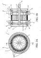
- the Figures 1A and 1B thus represent a first embodiment of the invention in which the heat generator 1 comprises a structural element 8 in the form of a solid ring (shown on the left on the Figure 1B ) and a structural element 9 in the form of a ring provided with fins (shown on the right on the Figure 1 B) .
- FIGS. 2A and 2B represent, for their part, an embodiment of the heat generator 10 in which the two structural elements 8 and 9 forming the thermal energy transfer means at the hot and cold rooms 5 include rings. In this circular configuration of the thermal generator 10, these rings extend radially.
- FIGS. 3A and 3B represent a structural element 8 (left on the figure 3B ) having circular fins, in the form of concentric rings around the axis A of the thermal generator 100 and a structural element 9 (shown to the right on the figure 3B ) having radially extending fins.
- the invention also provides that at least one structural element 8, 9 may comprise a circulation path 11 of a heat transfer fluid.
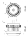
- a generator 1000 comprising such a structural element 8 is represented on the Figures 4A to 4C . It is associated with a second structural element 9 comprising radial fins.
- the heat generator 1, 10, 100, 1000 may comprise one or more thermal modules 3. These are then arranged adjacent to each other.
- the advantage inherent to the implementation of several thermal modules is obtaining a greater power, proportional to the number of thermal modules, since the means 8, 9 transfer of energy at several chambers 5, 6.
- the latter may comprise a plurality of thermal modules 3 arranged in a circle around a central axis A and the magnetic arrangement 7 may be concentric with this axis. central and rotated around it. All the figures of the attached drawings show this variant embodiment.
- the number of thermal modules 3 is not limiting and is determined according to the given application.
- the latter may extend radially around the chambers 5, 6, or circularly around them.
- the structural element 9 shown to the right on the Figures 1B , 3B and 4B and the two structural elements 8 and 9 of the thermal generator of the Figure 2B have radially extending fins, while the structural element shown to the left on the figure 3B comprises circular fins, in the form of concentric rings around the axis A of the thermal generator 100.
- the thermal generator according to the invention may comprise two identical structural elements 8 and 9, and made according to the any of the described embodiments. The choice of the structure of the structural elements will be dictated by the constraints of the type congestion, implementation in the final application, cost, conductivity and intrinsic thermal diffusion of said structural elements.
- the latter may comprise several thermal modules 3 aligned and arranged adjacently and the magnetic arrangement 7 can be driven in translation alternative along said thermal modules 3.
- the heat generator may comprise two thermally conductive casings 2, 2 'each integrating each hot chamber 5, respectively each cold room 6, and disposed on either side of each magnetocaloric element 4 and at least one structural element 8, 9 can be fixed on a housing 2, 2 'of the heat generator 1, 10, 100, 1000.
- the heat generator may comprise two thermally conductive casings 2, 2 'each integrating each hot chamber 5, respectively each cold chamber 6, and disposed on either side of each magnetocaloric element 4 and at least one structural element.
- 8, 9 can be in one piece with a casing 2, 2 'of the thermal generator 1, 10, 100, 1000.
- a structural element 8, 9 is fixed on the casing 2, 2' of the thermal generator 1 , 10, 100, 1000, this fixation can be achieved by gluing, soldering, brazing or any other similar means
- each thermal module 3 can incorporate circulation means 12 causing the alternating displacement of the coolant, from one chamber to another through the magnetocaloric element 4.
- these circulation means 12 may be in the form of a pair of pistons located on either side of the magnetocaloric element 4 and animated by a synchronized translational movement alternated by a drive mechanism 13.
- the mechanism 13 may, for its part, comprise at least one cam of control 14 driven by an actuator and having a cam profile 15 of substantially sinusoidal shape, whose amplitude determines the stroke of the pistons 12 and whose sinusoidal phase corresponds generally to a heating cycle and a cooling cycle of each magnetocaloric element 4.
- each piston 12 pushes a calibrated volume of the coolant contained in the thermal module 3 concerned through the magnetocaloric element 4 in a direction of circulation according to whether said magnetocaloric element 4 undergoes a heating cycle or in the direction opposite during a cooling cycle.
- These pistons 12 are preferably aligned and located in the axis of the magnetocaloric element 4 and move in an identical direction, and their housing form a chamber 5, 6.
- the cam profile 15 forms a protruding rib housed in a groove 16 corresponding to each piston 12.
- a circular-shaped heat generator 1, 10, 100, 1000 such as that shown in the set of appended figures, which comprises two control cams 14, the latter may have an annular shape and be driven in continuous rotation or not around the central axis A by an electric motor or any equivalent actuator.
- the cams are rectilinear and animated by an alternative translational movement.
- the magnetic arrangement 7 is formed of magnetized zones.
- ZA and non-magnetized zones NZ alternated and is coupled to an actuator to be movable relative to the magnetocaloric elements 4 and each pair formed by a magnetized zone ZA and a non magnetized zone NZ can extend over a distance corresponding generally to a sinusoid of the cam profile 15.
- the magnetized zone ZA thus generates a heating cycle of each magnetocaloric element 4 and the non magnetized zone NZ a cooling cycle.
- the actuator may be an electric motor or any other equivalent actuator capable of causing the magnetic arrangement 7 to rotate about the central axis A.
- the magnetic arrangement 7 comprises four pairs each formed by a zone magnet ZA and an unmagnetized zone NZ, and extending over a 90 ° angular sector and the cam profile 15 also corresponding four sinusoids each extending on the same angular sector.
- the heat transfer fluid used is preferably liquid.
- This fluid can be liquid, gaseous or diphasic. If it is liquid, one will use for example pure water for positive temperatures and water added antifreeze, for example a glycol product or a brine for negative temperatures.
- thermo generator 1, 10, 100, 1000 whose performance is guaranteed and is not influenced by the external circuit of use.
- a heat generator 1, 10, 100, 1000 can find an industrial as well as domestic application in the field of heating, air conditioning, tempering, cooling or other, at competitive costs and in a small footprint.
- this heat generator 1, 10, 100, 1000 can be made according to reproducible industrial processes.
Description
La présente invention se rapporte au domaine de la génération d'énergie thermique et concerne plus particulièrement un générateur thermique destiné à être relié à au moins une application en vue d'un échange d'énergie thermique avec cette dernière, ledit générateur comportant au moins un module thermique, ce module thermique comprenant essentiellement un élément magnétocalorique susceptible d'être traversé par un volume défini de fluide caloporteur entraîné dans le module thermique selon un déplacement alterné entre deux chambres dites chambre chaude et chambre froide disposées de part et d'autre dudit élément magnétocalorique, ledit générateur comportant également un arrangement magnétique agencé pour soumettre alternativement chaque élément magnétocalorique à une variation de champ magnétique et créer alternativement dans chaque élément magnétocalorique un cycle d'échauffement et un cycle de refroidissement, entraînant la création puis le maintien d'un gradient de température entre les deux extrémités opposées de chaque élément magnétocalorique situées au niveau des chambres, le déplacement alterné du fluide caloporteur étant synchronisé avec la variation du champ magnétique, et ledit générateur thermique comportant un moyen de transfert d'énergie thermique entre le liquide caloporteur d'au moins chaque chambre chaude et/ou d'au moins chaque chambre froide et chaque application ou l'environnement extérieur.The present invention relates to the field of thermal energy generation and more particularly relates to a thermal generator intended to be connected to at least one application for a heat energy exchange with the latter, said generator comprising at least one thermal module, this thermal module essentially comprising a magnetocaloric element capable of being traversed by a defined volume of coolant entrained in the thermal module according to an alternating displacement between two chambers called hot chamber and cold chamber arranged on either side of said element magnetocaloric, said generator also comprising a magnetic arrangement arranged to alternately subject each magnetocaloric element to a magnetic field variation and alternately create in each magnetocaloric element a heating cycle and a cooling cycle, resulting in the creation and maintaining a temperature gradient between the two opposite ends of each magnetocaloric element located at the chambers, the alternating displacement of the coolant being synchronized with the variation of the magnetic field, and said thermal generator comprising a means of energy transfer thermal between the coolant of at least each hot chamber and / or at least each cold room and each application or the external environment.
La technologie du froid magnétique est connue depuis une vingtaine d'années et on sait les avantages qu'elle apporte en termes d'écologie et de développement durable. On connaît également ses limites quant à sa puissance calorifique utile et à son rendement. Dès lors, les recherches menées dans ce domaine tendent toutes à améliorer les performances d'un tel générateur, en jouant sur les différents paramètres, tels que la puissance d'aimantation, les performances de l'élément magnétocalorique, la surface d'échange entre le fluide caloporteur et chaque élément magnétocalorique, les performances des échangeurs de chaleur, etc.The magnetic cold technology has been known for twenty years and we know the benefits it brings in terms of ecology and sustainable development. Its limits are also known as to its useful calorific power and its efficiency. Therefore, research in this area all tends to improve the performance of such a generator, playing on different parameters, such as the magnetization power, the performance of the magnetocaloric element, the exchange surface between the heat transfer fluid and each magnetocaloric element, the performance of the heat exchangers, etc.
Le document
En outre, dans les générateurs thermiques connus utilisant des éléments magnétocaloriques, le générateur est réalisé de manière à être totalement isolé thermiquement par rapport à l'environnement extérieur et les calories ou frigories produites sont récupérées ou prélevées via le fluide caloporteur du générateur mis en circulation dans un ou plusieurs échangeurs thermiques auxquels ce dernier est raccordé. Ce mode de transfert d'énergie ne permet pas de garantir des fonctions thermiques stables et un maintien du gradient de température dans les éléments magnétocaloriques si les conditions extérieures varient et que la quantité d'énergie ainsi prélevée (de manière intentionnelle ou non) dans le fluide caloporteur devient trop importante.In addition, in known thermal generators using magnetocaloric elements, the generator is made to be completely isolated thermally relative to the external environment and the calories or frigories produced are recovered or collected via the coolant of the generator circulated in one or more heat exchangers to which the latter is connected. This mode of energy transfer does not make it possible to guarantee stable thermal functions and maintenance of the temperature gradient in the magnetocaloric elements if the external conditions vary and the amount of energy thus withdrawn (intentionally or not) in the heat transfer fluid becomes too important.
A cet effet, les documents
La présente invention vise à pallier ces inconvénients en proposant un procédé de conception d'un générateur, thermique économiquement rentable, facile à mettre en oeuvre, dont le rendement est garanti et dans lequel le gradient dans chaque élément magnétocalorique est obtenu et maintenu automatiquement.The present invention aims to overcome these drawbacks by proposing a method for designing an economically efficient, easy-to-use thermal generator, whose efficiency is guaranteed and in which the gradient in each magnetocaloric element is obtained and maintained automatically.
Dans ce but, l'invention concerne un procédé de conception d'un générateur thermique suivant la revendication1, et un générateur thermique conçu suivant ledit procédé.For this purpose, the invention relates to a method of designing a thermal generator according to
La présente invention sera mieux comprise grâce à la description ci-après qui se rapporte à des modes de réalisation préférés donnés à titre d'exemples non limitatifs et expliqués avec référence aux dessins schématiques annexés, dans lesquels :
- la
figure 1A est une vue en élévation frontale et en transparence d'un générateur thermique selon un premier mode de réalisation de l'invention, - la
figure 1B est une vue en coupe selon le plan C-C de lafigure 1A , - la
figure 2A est une vue en élévation frontale et en transparence d'un générateur thermique selon un second mode de réalisation de l'invention, - la
figure 2B est une vue en coupe selon le plan B-B de lafigure 2A , - la
figure 3A est une vue en élévation frontale et en transparence d'un générateur thermique selon un troisième mode de réalisation de l'invention, - la
figure 3B est une vue en coupe selon le plan D-D de lafigure 3A , - la
figure 4A est une vue en élévation frontale et en transparence d'un générateur thermique selon un quatrième mode de réalisation de l'invention, - la
figure 4B est une vue en coupe selon le plan C-C de lafigure 4A , - la
figure 4C est une vue en élévation latérale du générateur thermique représenté auxfigures 4A et 4B , et - la
figure 4D est une vue en coupe selon le plan E-E de lafigure 4C .
- the
Figure 1A is a front elevation and in transparency of a thermal generator according to a first embodiment of the invention, - the
Figure 1B is a sectional view along the plane CC of theFigure 1A , - the
Figure 2A is a frontal elevational view in transparency of a thermal generator according to a second embodiment of the invention, - the
Figure 2B is a sectional view along the plane BB of theFigure 2A , - the
figure 3A is a frontal elevational view in transparency of a thermal generator according to a third embodiment of the invention, - the
figure 3B is a sectional view along the plane DD of thefigure 3A , - the
Figure 4A is a front elevational view in transparency of a thermal generator according to a fourth embodiment of the invention, - the
Figure 4B is a sectional view along the plane CC of theFigure 4A , - the
figure 4C is a side elevational view of the thermal generator shown inFigures 4A and 4B , and - the
figure 4D is a sectional view according to the EE plan of thefigure 4C .
Les figures des dessins annexés représentent un générateur thermique 1, 10, 100, 1000 selon l'invention. Ce dernier est destiné à être relié à au moins une application en vue d'un échange d'énergie thermique avec cette dernière et comporte au moins un module thermique 3, ce module thermique 3 comprenant essentiellement un élément magnétocalorique 4 susceptible d'être traversé par un volume défini de fluide caloporteur entraîné dans le module thermique 3 selon un déplacement alterné entre deux chambres 5, 6 dites chambre chaude et chambre froide disposées de part et d'autre dudit élément magnétocalorique 4, ledit générateur comportant également un arrangement magnétique 7 agencé pour soumettre alternativement chaque élément magnétocalorique 4 à une variation de champ magnétique et créer alternativement dans chaque élément magnétocalorique 4 un cycle d'échauffement et un cycle de refroidissement, entraînant la création et le maintien d'un gradient de température entre les deux extrémités opposées de chaque élément magnétocalorique situées au niveau des chambres 5 (coté le plus chaud de l'élément magnétocalorique) et 6 (coté le plus froid de l'élément magnétocalorique), le déplacement alterné du fluide caloporteur étant synchronisé avec la variation du champ magnétique, et ledit générateur thermique 1, 10, 100, 1000 comportant un moyen 8, 9 de transfert d'énergie thermique entre le liquide caloporteur d'au moins chaque chambre chaude 5 et/ou d'au moins chaque chambre froide 6 et chaque application ou l'environnement extérieur. Le déplacement alterné du fluide caloporteur à l'intérieur de chaque module thermique 3, associé à un cycle d'échauffement et un cycle de refroidissement thermodynamique, appelé également Cycle AMRR (Active Magnetic Refrigeration Regenerator), permet d'augmenter le gradient de température entre les deux extrémités de l'élément magnétocalorique 4 et donc entre les deux chambres 5 et 6.The figures of the attached drawings show a
Le générateur 1, 10, 100, 1000 selon l'invention est réalisé de telle sorte que le transfert d'énergie thermique par l'intermédiaire du moyen 8, 9 est limité volontairement et stabilisé de manière à empêcher une diminution non contrôlée du gradient de température présent dans chaque élément magnétocalorique 4.The
Par transfert d'énergie, il faut comprendre échange d'énergie avec l'application destinée à être reliée au générateur thermique 1, 10, 100, 1000 selon l'invention ou avec l'environnement extérieur, le cas échéant. On comprend donc qu'il peut s'agir de l'extraction ou du prélèvement des calories et/ou frigories réalisées par le générateur et stockées dans les chambres chaudes 5 et froides 6 ou de l'absorption de l'énergie thermique de l'application ou de l'environnement.By energy transfer, it is necessary to understand energy exchange with the application intended to be connected to the
L'invention propose de rendre le fonctionnement du générateur, et plus précisément son rendement, indépendants de l'application bouclée à ce dernier en limitant et contrôlant les transferts d'énergie entre le fluide caloporteur des chambres chaudes et froides et l'application. Cette limitation et ce contrôle sont réalisés grâce aux différentes interfaces d'échange thermique entre le fluide caloporteur et l'application et notamment par la présence du moyen 8, 9 de transfert configuré de manière à n'autoriser le passage ou le transfert que d'une quantité limitée d'énergie thermique, garantissant ainsi une valeur minimale du gradient thermique de chaque élément caloporteur, dont dépend le rendement thermique du générateur.The invention proposes to make the operation of the generator, and more precisely its efficiency, independent of the application looped to the latter by limiting and controlling the energy transfer between the heat transfer fluid of the hot and cold rooms and the application. This limitation and this control are achieved thanks to the different heat exchange interfaces between the heat transfer fluid and the application and in particular by the presence of the transfer means 8, 9 configured so as to authorize the passage or the transfer only of a limited amount of thermal energy, thus guaranteeing a minimum value of the thermal gradient of each heat transfer element, on which the thermal efficiency of the generator depends.
Le moyen 8, 9 constitue simultanément un moyen de limitation de la quantité d'énergie pouvant être transférée ou échangée, de manière à ne pas dégrader le système et à conserver au moins une valeur prédéterminée du gradient de température dans chaque élément magnétocalorique 4. Cette valeur dépend notamment des flux thermiques échangés à chaque interface thermique, entre d'une part l'élément magnétocalorique et le fluide caloporteur, d'autre part entre le fluide caloporteur et chaque carter ou moyen de transfert thermiquement conducteur et enfin entre chaque carter ou moyen de transfert thermiquement conducteur et le fluide caloporteur (par exemple : l'air ambiant) assurant le transfert d'énergie entre le générateur thermique et l'application. Cette valeur dépend encore des matériaux utilisés pour la réalisation de chaque élément magnétocalorique 4, des propriétés thermiques de la matière utilisée pour construire chaque moyen de transfert ou carter 2, 2' éventuel, du volume et des propriétés physiques et thermiques du fluide caloporteur choisi.The
L'objectif de l'invention est obtenu par la présence du moyen 8, 9 de transfert. Le principe consiste à maîtriser par construction les propriétés des échanges thermiques, d'une part, entre l'élément magnétocalorique et le fluide caloporteur, et, d'autre part, entre le fluide caloporteur du générateur et le fluide caloporteur assurant le transfert d'énergie entre le générateur thermique et l'application (qui peut être par exemple l'air ambiant), en considérant également les échanges avec un éventuel carter thermiquement conducteur disposé entre les chambres et le moyen de transfert d'énergie. Le moyen de transfert d'énergie fonctionne de manière à limiter les transferts d'énergie quelles que soient les conditions extrêmes auxquelles sont soumis les éléments en contact avec le fluide caloporteur de l'application.The objective of the invention is obtained by the presence of the transfer means 8, 9. The principle consists in controlling, by construction, the properties of the heat exchange, on the one hand, between the magnetocaloric element and the coolant, and, on the other hand, between the heat transfer fluid of the generator and the heat transfer fluid ensuring the transfer of heat transfer medium. energy between the heat generator and the application (which may be for example the ambient air), also considering the exchanges with a possible thermally conductive casing disposed between the chambers and the energy transfer means. The energy transfer means operates in such a way as to limit the energy transfers whatever the extreme conditions to which the elements in contact with the heat-transfer fluid of the application are subjected.
Le moyen de transfert 8, 9 d'énergie thermique fonctionne donc à la manière d'un goulot d'étranglement qui régule et limite la quantité d'énergie pouvant être transférée. En d'autres termes, cette quantité d'énergie pouvant être transférée est équivalente à une fuite thermique qui correspond exactement à la puissance utile attendue du générateur thermique 1, 10, 100, 1000 selon l'invention.The thermal energy transfer means 8, 9 therefore operates in the manner of a bottleneck that regulates and limits the amount of energy that can be transferred. In other words, this amount of energy that can be transferred is equivalent to a thermal leakage that corresponds exactly to the expected power output of the
Grâce à l'invention, il est possible de limiter et contrôler la quantité d'énergie thermique, donc de calories ou frigories pouvant être transférées au niveau du générateur thermique 1, 10, 100, 1000. De cette manière, une valeur minimale du gradient de température est garantie et maintenue à l'intérieur de chaque module thermique 3. Etant donné que le rendement d'un tel générateur thermique 1, 10, 100, 1000 dépend majoritairement de ce gradient de température, l'invention permet d'optimiser ce rendement. En d'autres termes, le moyen de transfert 8, 9 d'énergie thermique, limitée et stabilisée aux niveaux des interfaces thermiques permet de réduire fortement l'influence extérieure due au prélèvement ou transfert d'énergie thermique au niveau du générateur thermique 1, 10, 100, 1000.Thanks to the invention, it is possible to limit and control the amount of thermal energy, therefore calories or frigories that can be transferred to the
L'élément magnétocalorique 2 peut comprendre un matériau réalisé en partie ou en totalité dans une matière magnétocalorique telle que par exemple du gadolinium (Gd), un alliage de gadolinium comportant du silicium, du Germanium (Ge), du fer (Fe), du magnésium (Mg), du phosphore (P), de l'arsenic (As), ou tout autre matériau équivalent. Ce matériau peut être sous la forme d'un bloc plein, fritté ou poreux, de pastilles, de poudre, d'agglomérat, de morceaux ou sous la forme de tronçons partiellement cylindriques découpés, usinés et/ou moulés dans un matériau magnétocalorique. Le choix du matériau et de sa forme sont faits en fonction des puissances thermiques (caloriques et frigorifiques) recherchées et du gradient de température requis pour assurer les échanges thermiques avec l'application. Chaque élément magnétocalorique 2 est perméable au fluide caloporteur et comporte à cet effet des passages de fluide débouchant qui peuvent être constitués par les pores d'un matériau poreux, des mini ou micro-canaux usinés dans un bloc plein où obtenus par un assemblage de plaques rainurées superposées, par exemple.The
Le moyen de transfert d'énergie thermique peut être constitué par au moins un élément structurel 8, 9 disposé au niveau de chaque chambre chaude 5 ou froide 6 de manière à présenter une surface de contact avec la paroi de chaque chambre chaude 5 ou froide 6 pour transférer par conduction et convection thermiques une quantité limitée de calories ou de frigories, et le coefficient global de transmission thermique de chaque élément structurel 8, 9 peut être déterminé en fonction du coefficient de transmission thermique au niveau de chaque interface de transfert thermique située entre chaque élément magnétocalorique 4 et chaque élément structurel 8, 9.The thermal energy transfer means may consist of at least one
Ces interfaces de transfert thermique sont les suivantes : les surfaces d'échange entre chaque élément magnétocalorique 4 et le fluide caloporteur le ou les traversant, entre le fluide caloporteur et la paroi des chambres chaudes 5 et froides 6, entre la paroi desdites chambres et le moyen de transfert 8, 9 et entre le moyen de transfert 8, 9 et le fluide caloporteur de l'application (par exemple l'air ambiant). Elles participent à la limitation de l'énergie thermique du générateur susceptible d'être échangée avec une application.These heat transfer interfaces are as follows: the exchange surfaces between each
Le générateur thermique est relié à au moins une application avec laquelle il est destiné à échanger de l'énergie thermique ce, par l'intermédiaire du moyen 8, 9 de transfert et le coefficient global de transmission thermique du générateur thermique 1, 10, 100, 1000 peut être déterminé en fonction du coefficient de transmission thermique au niveau de l'interface thermique entre chaque élément magnétocalorique 4 et le fluide caloporteur le traversant, entre ledit fluide caloporteur et la paroi de la chambre 5, 6 associée, entre la paroi de chaque chambre 5, 6 et le moyen 8, 9 de transfert correspondant et entre le moyen 8, 9 de transfert et chaque application concernée.The thermal generator is connected to at least one application with which it is intended to exchange thermal energy ce, via the transfer means 8, 9 and the overall coefficient of thermal transmission of the
Comme celà est représenté dans l'ensemble des figures, le moyen de transfert d'énergie thermique est destiné à transférer de l'énergie thermique au niveau de chaque chambre chaude 5 et de chaque chambre froide 6 et être constitué par deux éléments structurels 8 et 9 disposés respectivement au niveau de chaque chambre chaude 5 et au niveau de chaque chambre froide 6. Ces éléments structurels 8 et 9 sont alors disposés au niveau des chambres chaudes 5 respectivement froides 6 de manière à présenter une surface de contact avec la paroi de chaque chambre chaude 5, respectivement froide 6 pour transférer par conduction et convection thermiques, de chaque chambre concernée 5, 6, une quantité limitée et contrôlée d'énergie thermique. Ces éléments structurels 8 et 9 permettent donc de transférer une quantité limitée de calories et frigories issues des chambres 5 et 6. Le ou les matériaux constitutifs de ces éléments structurels 8, 9 ainsi que leur forme ou configuration seront, bien entendu, choisis en fonction des performances du générateur thermique 1, 10, 100, 1000 et de la valeur du gradient de température devant être conservée.As shown in all the figures, the heat energy transfer means is intended to transfer heat energy at each
Dans l'invention, le moyen 8, 9 de transfert garantit le rendement du générateur thermique 1, 10, 100, 1000 selon l'invention. Quelle que soit la demande de transfert ou d'échange thermique requise par l'application extérieure liée audit générateur thermique 1, 10, 100, 1000, cette demande ne sera satisfaite que dans la mesure où elle n'a pas d'influence, ni ne dégrade le gradient de température présent dans chaque module thermique 3.In the invention, the transfer means 8, 9 guarantees the efficiency of the
En effet, si le gradient thermique au sein des modules thermiques 3 se dégrade, voire s'annule, le rendement thermique du générateur thermique est nul. Il est nécessaire de ré-établir ce gradient thermique pour pouvoir produire à nouveau de l'énergie thermique et la fournir à l'extérieur du générateur thermique 1, 10, 100, 1000. Dans tous les cas, le moyen de transfert d'énergie est conçu de manière à contrôler intrinsèquement et encadrer automatiquement, par des valeurs limites dépendant des différents coefficients d'échange entre les différentes interfaces disposées en série entre le matériau magnétocalorique et l'application extérieur, la quantité d'énergie thermique susceptible d'être échangée. Cette quantité d'énergie disponible (interne) est, bien entendu, déterminée selon l'invention lors de la conception du générateur 1, 10, 100, 1000, en fonction de ses caractéristiques, à savoir notamment de la nature et de la quantité de l'élément magnétocalorique 2, du fluide caloporteur et du type de champ magnétique généré par l'arrangement magnétique 7.Indeed, if the thermal gradient within the
En d'autres termes, l'on maîtrise la chaine (en série) d'échanges thermiques (et de coefficients d'échange) aux différentes interfaces d'échange thermique (élément magnétocalorique 4/fluide caloporteur, fluide caloporteur/paroi de la chambre 5, 6 concernée, paroi de ladite chambre 5, 6/élément structurel 8, 9 et élément structurel 8, 9/milieu d'échange thermique de l'application extérieures) afin de contrôler le flux thermique à travers le générateur thermique 1, 10, 100, 1000. Pour ce faire, ces différents coefficient d'échanges « h » sont ajustés entre eux par paires associées en série, c'est-à-dire qu'ils sont choisis de telle sorte que la quantité d'énergie thermique susceptible d'être échangée avec l'application extérieure est limitée, à savoir comprise dans un intervalle de valeurs prédéfinies.In other words, we control the chain (in series) of heat exchange (and exchange coefficients) to the different heat exchange interfaces (
Cette configuration préserve le gradient thermique de l'appareil, même si les conditions externes varient très fortement. Un équilibre thermique se créera pour aboutir, d'un coté de la chaîne d'échanges thermiques, à la température externe de l'élément structurel 8, 9 (surface externe dudit élément structurel) et, de l'autre coté de la chaîne, à la température de l'extrémité de l'élément magnétocalorique 4 consistant en la valeur de température extrême (côté chaud ou froid) du gradient thermique.This configuration preserves the thermal gradient of the device, even if the external conditions vary very strongly. A thermal equilibrium will be created for result, on one side of the heat exchange chain, the external temperature of the
Selon l'invention, au moins un élément structurel 8, 9 peut être sous la forme d'un anneau massif dont au moins une partie de la surface est en contact avec la paroi de la chambre concernée 5, 6. Un tel anneau est notamment représenté sur les
En variante ou de manière additionnelle, il peut également être prévu qu'au moins un élément structurel 8, 9 peut être réalisé sous la forme d'un anneau muni d'ailettes.Alternatively or additionally, it can also be provided that at least one
Comme cela ressort des figures annexées, l'élément structurel 8, 9 et l'extrémité concernée de l'élément magnétocalorique 4 sont disposées dans un voisinage restreint. Cette proximité permet d'augmenter l'efficacité du générateur thermiques et évite d'avoir recours à l'installation de grandes longueurs de canalisations qui pénalisent l'échange thermique et l'efficacité du système. Cette configuration permet ainsi le fonctionnement du générateur thermique à des fréquences alternées élevées et d'obtenir une maîtrise de la puissance thermique. En d'autres termes, cela consiste à limiter l'appel thermique issu de l'application extérieure qui pourrait dégrader (s'il n'y avait pas de contrôle des différents échanges thermiques) le gradient thermique du générateur thermique magnétocalorique. L'invention permet d'obtenir rapidement à la fois un gradient thermique (« span » en anglais) stable et élevé et un échange thermique avec l'application qui se comporte comme une diode de régulation électronique (diode Zener) et qui stabilise la différence de température entre les deux extrémités de la chaîne d'échanges thermiques.As is apparent from the accompanying figures, the
Les
Les
Les
L'invention prévoit également qu'au moins un élément structurel 8, 9 peut comprendre un chemin de circulation 11 d'un fluide caloporteur. Un générateur 1000 comportant un tel élément structurel 8 est représenté sur les
Bien entendu, en fonction de l'application et de puissance thermique à fournir, le générateur thermique 1, 10, 100, 1000 peut comporter un ou plusieurs modules thermiques 3. Ces derniers sont alors disposés de manière adjacente les uns aux autres. L'avantage inhérent à l'implantation de plusieurs modules thermiques est l'obtention d'une puissance plus importante, proportionnelle au nombre de modules thermiques, étant donné que le moyen 8, 9 transfert de l'énergie au niveau de plusieurs chambres 5, 6.Of course, depending on the application and the thermal power to be supplied, the
Selon une première variante de réalisation du générateur thermique 1, 10, 100, 1000, ce dernier peut comporter plusieurs modules thermiques 3 disposés de manière adjacente en cercle autour d'un axe central A et l'arrangement magnétique 7 peut être concentrique à cet axe central et entraîné en rotation autour de ce dernier. L'ensemble des figures des dessins annexés représentent cette variante de réalisation. Le nombre de modules thermiques 3 n'est pas limitatif et est déterminé en fonction de l'application donnée.According to a first variant embodiment of the
Dans le mode de réalisation du moyen 8, 9 dans lequel au moins un des éléments structurels le composant comporte des ailettes, ces dernières peuvent s'étendre radialement autour des chambres 5, 6, ou encore circulairement autour de ces dernières. L'élément structurel 9 représenté à droite sur les
Selon une seconde variante non représentée du générateur thermique 1, 10, 100, 1000, ce dernier peut comporter plusieurs modules thermiques 3 alignés et disposés de manière adjacente et l'arrangement magnétique 7 peut être entraîné en translation alternative le long desdits modules thermiques 3.According to a second variant not shown of the
En ce qui concerne le mode de montage ou de fixation du moyen 8, 9 de transfert d'énergie thermique, selon une première variante, le générateur thermique peut comporter deux carters 2, 2' thermiquement conducteurs intégrant chacun chaque chambre chaude 5, respectivement chaque chambre froide 6, et disposés de part et d'autre de chaque élément magnétocalorique 4 et au moins un élément structurel 8, 9 peut être fixé sur un carter 2, 2' du générateur thermique 1, 10, 100, 1000.With regard to the method of mounting or fixing the thermal energy transfer means 8, 9, according to a first variant, the heat generator may comprise two thermally
Selon une seconde variante, le générateur thermique peut comporter deux carters 2, 2' thermiquement conducteurs intégrant chacun chaque chambre chaude 5, respectivement chaque chambre froide 6, et disposés de part et d'autre de chaque élément magnétocalorique 4 et au moins un élément structurel 8, 9 peut être d'un seul tenant avec un carter 2, 2' du générateur-thermique 1, 10, 100, 1000. Lorsqu'un élément structurel 8, 9 est fixé sur la carter 2, 2' du générateur thermique 1, 10, 100, 1000, cette fixation peut être réalisée par collage, soudure, brasage ou tout autre moyen analogueAccording to a second variant, the heat generator may comprise two thermally
Pour permettre de faire circuler le fluide caloporteur dans chaque module thermique 3 selon un mouvement de va-et-vient d'une chambre 5, 6 à l'autre 6, 5 en traversant à chaque fois l'élément magnétocalorique 4 situé entre les deux chambres 5, 6, chaque module thermique 3 peut intégrer des moyens de circulation 12 entraînant le déplacement alterné du fluide caloporteur, d'une chambre à l'autre à travers l'élément magnétocalorique 4.To make it possible to circulate the heat transfer fluid in each
De manière avantageuse, et comme cela ressort plus particulièrement des
Dans le cas d'un générateur thermique 1, 10, 100, 1000 de forme circulaire, tel que celui représenté dans l'ensemble des figures annexées, qui comporte deux cames de commande 14, ces dernières peuvent présenter une forme annulaire et être entraînées en rotation continue ou non autour de l'axe central A par un moteur électrique ou tout actionneur équivalent.In the case of a circular-shaped
Dans le cas d'un générateur thermique de forme linéaire (non représenté), les cames sont rectilignes et animées d'un mouvement de translation alternative.In the case of a thermal generator of linear form (not shown), the cams are rectilinear and animated by an alternative translational movement.
Toujours dans le cas d'un générateur thermique 1, 10, 100, 1000 circulaire, dans lequel les modules thermiques 3 sont agencés circulairement autour d'un axe central A, il peut être prévu que l'arrangement magnétique 7 soit formé de zones aimantées ZA et de zones non aimantées NZ alternées et soit couplé à un actionneur pour être mobile par rapport aux éléments magnétocaloriques 4 et chaque couple formé par une zone aimantée ZA et une zone non aimantée NZ peut s'étendre sur une distance correspondant globalement à une sinusoïde du profil de came 15. La zone aimantée ZA génère ainsi un cycle d'échauffement de chaque élément magnétocalorique 4 et la zone non aimantée NZ un cycle de refroidissement. L'actionneur peut être un moteur électrique ou tout autre actionneur équivalent susceptible d'entraîner l'arrangement magnétique 7 en rotation autour de l'axe central A. Dans les exemples illustrés, l'arrangement magnétique 7 comporte quatre couples formés chacun par une zone aimantée ZA et une zone non aimantée NZ, et s'étendant sur un secteur angulaire de 90° et le profil de came 15 comporte en correspondance également quatre sinusoïdes s'étendant chacune sur le même secteur angulaire.Still in the case of a circular
Le fluide caloporteur utilisé est de préférence liquide. On choisira une composition chimique du fluide caloporteur adaptée à la plage de température voulue afin d'obtenir un échange thermique maximal. Ce fluide peut donc être liquide, gazeux ou diphasique. S'il est liquide, on utilisera par exemple de l'eau pure pour des températures positives et de l'eau additionnée d'antigel, par exemple un produit glycolé ou une saumure pour des températures négatives.The heat transfer fluid used is preferably liquid. We will choose a chemical composition of the heat transfer fluid adapted to the desired temperature range to obtain maximum heat exchange. This fluid can be liquid, gaseous or diphasic. If it is liquid, one will use for example pure water for positive temperatures and water added antifreeze, for example a glycol product or a brine for negative temperatures.
Grâce au procédé selon l'invention, il est donc possible de réaliser un générateur thermique 1, 10, 100, 1000 dont le rendement est garanti et n'est pas influencé par le circuit extérieur d'utilisation. Un tel générateur thermique 1, 10, 100, 1000 peut trouver une application aussi bien industrielle que domestique dans le domaine du chauffage, de la climatisation, du tempérage, refroidissement ou autres, ce, à des coûts compétitifs et dans un faible encombrement.Thanks to the method according to the invention, it is therefore possible to produce a
En outre, toutes les pièces composant ce générateur thermique 1, 10, 100, 1000 peuvent être réalisées selon des processus industriels reproductibles.In addition, all the components of this
Claims (13)
- Method of designing a thermal generator (1, 10, 100, 1000) intended to be connected with at least one external application for a thermal energy exchange with the latter, said generator including at least one thermal module (3), this thermal module (3) comprising essentially a magnetocaloric element (4) through which a defined volume of heat transfer fluid can flow, which is circulated in the thermal module (3) according to a reciprocating displacement between two chambers (5, 6) called hot chamber and cold chamber, arranged on either side of said magnetocaloric element (4), said generator comprising also a magnetic arrangement (7) arranged to subject alternately every magnetocaloric element (4) to a variation of the magnetic field and create alternately in every magnetocaloric element (4) a heating cycle and a cooling cycle, leading to the creation and holding of a temperature gradient between the two opposite ends of every magnetocaloric element (4) located close to the chambers (5, 6), the reciprocating circulation of the heat transfer fluid being synchronized with the variation of the magnetic field and said thermal generator (1, 10, 100, 1000) comprising a means (8, 9) for transferring thermal energy between the heat transfer fluid of at least every hot chamber (5) and/or at least every cold chamber (6) and every application or the external environment, method characterized in that the heat exchange coefficients between the various heat exchange interfaces (magnetocaloric element 4/heat transfer fluid - heat transfer fluid/wall of chamber 5, 6 - wall of said chamber 5, 6/transfer means 8, 9 and transfer means 8, 9/heat exchange medium of the application or of the external environment) are adjusted serially in associated pairs so that the quantity of thermal energy liable to be exchanged with the application or with the external environment is limited in order to preserve the thermal gradient in every thermal module (3) and so that the thermal exchange demand of the application or the external environment is met only insofar it does neither influence nor reduce the temperature gradient present in every thermal module (3).
- Thermal generator designed according to the method of claim 1, characterized in that the thermal energy transfer means comprises at least one structural element (8, 9) having a contact surface with the wall of every hot (5) or cold (6) chamber.
- Thermal generator according to claim 2, characterized in that the transfer means (8, 9) is intended for transferring thermal energy at the level of every hot chamber (5) and of every cold chamber (6) and is made of two structural elements (8 and 9) arranged respectively at the level of every hot chamber (5) and at the level of every cold chamber (6).
- Thermal generator according to any of claims 2 to 3, characterized in that at least one structural element (8, 9) forming the transfer means has the shape of a massive ring of which at least a part of the surface is in contact with the wall of the concerned chamber (5, 6).
- Thermal generator according to any of claims 2 to 4, characterized in that at least one structural element (8, 9) forming the transfer means has the shape of a ring provided with fins.
- Thermal generator according to any of claims 2 to 5, characterized in that at least one structural element (8, 9) forming the transfer means comprises a circulation path (11) of a heat transfer fluid.
- Thermal generator according to any of claims 2 to 6, characterized in that it comprises several thermal modules (3) arranged adjacently in a circle around a central axis (A) and in that the magnetic arrangement (7) is concentric to this central axis and driven in rotation around the latter.
- Thermal generator according to claims 5 and 7, characterized in that the fins extend radially around the chambers (5, 6).
- Thermal generator according to claims 5 and 7, characterized in that the fins extend circularly around the chambers (5, 6).
- Thermal generator according to any of claims 2 to 6, characterized in that it comprises several thermal modules (3) arranged adjacently on a line and in that the magnetic arrangement (7) is driven in a reciprocating translation along said thermal modules (3).
- Thermal generator according to any of claims 2 to 10, characterized in that every thermal module (3) includes circulation means (12) that ensure the reciprocating displacement of the heat transfer fluid from one chamber to the other through the magnetocaloric element (4).
- Thermal generator according to claim 11, characterized in that the circulation means (12) are formed by a pair of pistons located on either side of the magnetocaloric element (4) and driven in a reciprocating translation movement by a driving mechanism (13).
- Thermal generator according to claim 12, characterized in that the driving mechanism (13) comprises at least one guide curve (14) driven by an actuator and including a guiding profile (15) with a substantially sinusoidal shape whose amplitude determines the stroke of the pistons (12) and whose sinusoidal phase globally corresponds to a heating cycle and a cooling cycle of every magnetocaloric element (4).
Priority Applications (1)
| Application Number | Priority Date | Filing Date | Title |
|---|---|---|---|
| PL09784446T PL2318785T3 (en) | 2008-06-30 | 2009-06-29 | Magnetocaloric thermal generator |
Applications Claiming Priority (2)
| Application Number | Priority Date | Filing Date | Title |
|---|---|---|---|
| FR0803695A FR2933172B1 (en) | 2008-06-30 | 2008-06-30 | MAGNETOCALORIC THERMAL GENERATOR |
| PCT/FR2009/051256 WO2010004186A2 (en) | 2008-06-30 | 2009-06-29 | Magnetocaloric thermal generator |
Publications (2)
| Publication Number | Publication Date |
|---|---|
| EP2318785A2 EP2318785A2 (en) | 2011-05-11 |
| EP2318785B1 true EP2318785B1 (en) | 2015-05-27 |
Family
ID=40377252
Family Applications (1)
| Application Number | Title | Priority Date | Filing Date |
|---|---|---|---|
| EP09784446.8A Active EP2318785B1 (en) | 2008-06-30 | 2009-06-29 | Magnetocaloric thermal generator |
Country Status (5)
| Country | Link |
|---|---|
| EP (1) | EP2318785B1 (en) |
| ES (1) | ES2545979T3 (en) |
| FR (1) | FR2933172B1 (en) |
| PL (1) | PL2318785T3 (en) |
| WO (1) | WO2010004186A2 (en) |
Families Citing this family (1)
| Publication number | Priority date | Publication date | Assignee | Title |
|---|---|---|---|---|
| FR2982015B1 (en) * | 2011-10-28 | 2019-03-15 | Cooltech Applications | MAGNETOCALORIC THERMAL GENERATOR |
Family Cites Families (7)
| Publication number | Priority date | Publication date | Assignee | Title |
|---|---|---|---|---|
| JPS60204852A (en) * | 1984-03-30 | 1985-10-16 | Tokyo Inst Of Technol | Magnetic material for magnetic refrigeration |
| JPS6446545A (en) * | 1987-08-14 | 1989-02-21 | Hitachi Ltd | Magnetic refrigerator |
| US4956976A (en) * | 1990-01-24 | 1990-09-18 | Astronautics Corporation Of America | Magnetic refrigeration apparatus for He II production |
| JP2005090921A (en) * | 2003-09-19 | 2005-04-07 | Canon Inc | Temperature controlling device using magnetic body |
| JP4564883B2 (en) * | 2005-04-28 | 2010-10-20 | 中部電力株式会社 | Magnetic temperature controller |
| JP4533838B2 (en) * | 2005-12-06 | 2010-09-01 | 株式会社東芝 | Heat transport device, refrigerator and heat pump |
| JP4921890B2 (en) * | 2006-08-24 | 2012-04-25 | 中部電力株式会社 | Magnetic refrigeration equipment |
-
2008
- 2008-06-30 FR FR0803695A patent/FR2933172B1/en not_active Expired - Fee Related
-
2009
- 2009-06-29 WO PCT/FR2009/051256 patent/WO2010004186A2/en active Application Filing
- 2009-06-29 ES ES09784446.8T patent/ES2545979T3/en active Active
- 2009-06-29 PL PL09784446T patent/PL2318785T3/en unknown
- 2009-06-29 EP EP09784446.8A patent/EP2318785B1/en active Active
Also Published As
| Publication number | Publication date |
|---|---|
| WO2010004186A2 (en) | 2010-01-14 |
| PL2318785T3 (en) | 2015-12-31 |
| FR2933172B1 (en) | 2016-07-01 |
| ES2545979T3 (en) | 2015-09-17 |
| WO2010004186A8 (en) | 2010-07-08 |
| EP2318785A2 (en) | 2011-05-11 |
| FR2933172A1 (en) | 2010-01-01 |
| WO2010004186A3 (en) | 2010-03-25 |
Similar Documents
| Publication | Publication Date | Title |
|---|---|---|
| EP2215410B1 (en) | Thermal generator with magneto-caloric material | |
| EP2399087B1 (en) | Magnetocaloric heat generator | |
| EP2129976B1 (en) | Method and device for increasing a temperature gradient in a magnetocaloric thermal generator | |
| EP1730454B8 (en) | Heat generator comprising a magneto-caloric material and thermie generating method | |
| EP3355019B1 (en) | Cooling device | |
| EP2771628A1 (en) | Magnetocaloric heat generator | |
| WO2010061064A1 (en) | Thermal generator with magnetocaloric material | |
| EP3011249B1 (en) | Cooling of electronic and/or electrical components by pulsed heat pipe and heat conduction element | |
| EP2318785B1 (en) | Magnetocaloric thermal generator | |
| EP3087329B1 (en) | Magnetocaloric thermal generator and method of cooling same | |
| EP4169155B1 (en) | Machine for converting thermal energy into electrical energy or vice versa | |
| EP2972045A2 (en) | Thermal apparatus | |
| EP2368279B1 (en) | Method for quickly establishing a temperature gradient in a magnetocaloric element, and magnetocaloric thermal generator implementing said method | |
| WO2023222971A1 (en) | System for generating cold and for supplying electrical power from seawater and the sun | |
| FR2957137A1 (en) | Heat exchanger module for stirling engine utilized for boilers, has two exchangers, where one of exchangers is placed on two sides of other heat exchanger and operated at temperature different from that of former exchanger |
Legal Events
| Date | Code | Title | Description |
|---|---|---|---|
| PUAI | Public reference made under article 153(3) epc to a published international application that has entered the european phase |
Free format text: ORIGINAL CODE: 0009012 |
|
| 17P | Request for examination filed |
Effective date: 20101230 |
|
| AK | Designated contracting states |
Kind code of ref document: A2 Designated state(s): AT BE BG CH CY CZ DE DK EE ES FI FR GB GR HR HU IE IS IT LI LT LU LV MC MK MT NL NO PL PT RO SE SI SK TR |
|
| AX | Request for extension of the european patent |
Extension state: AL BA RS |
|
| DAX | Request for extension of the european patent (deleted) | ||
| 17Q | First examination report despatched |
Effective date: 20130404 |
|
| GRAP | Despatch of communication of intention to grant a patent |
Free format text: ORIGINAL CODE: EPIDOSNIGR1 |
|
| INTG | Intention to grant announced |
Effective date: 20140923 |
|
| GRAS | Grant fee paid |
Free format text: ORIGINAL CODE: EPIDOSNIGR3 |
|
| GRAP | Despatch of communication of intention to grant a patent |
Free format text: ORIGINAL CODE: EPIDOSNIGR1 |
|
| INTG | Intention to grant announced |
Effective date: 20150327 |
|
| GRAA | (expected) grant |
Free format text: ORIGINAL CODE: 0009210 |
|
| AK | Designated contracting states |
Kind code of ref document: B1 Designated state(s): AT BE BG CH CY CZ DE DK EE ES FI FR GB GR HR HU IE IS IT LI LT LU LV MC MK MT NL NO PL PT RO SE SI SK TR |
|
| REG | Reference to a national code |
Ref country code: GB Ref legal event code: FG4D Free format text: NOT ENGLISH |
|
| REG | Reference to a national code |
Ref country code: CH Ref legal event code: EP |
|
| REG | Reference to a national code |
Ref country code: AT Ref legal event code: REF Ref document number: 729080 Country of ref document: AT Kind code of ref document: T Effective date: 20150615 |
|
| REG | Reference to a national code |
Ref country code: IE Ref legal event code: FG4D Free format text: LANGUAGE OF EP DOCUMENT: FRENCH |
|
| REG | Reference to a national code |
Ref country code: DE Ref legal event code: R096 Ref document number: 602009031457 Country of ref document: DE |
|
| REG | Reference to a national code |
Ref country code: ES Ref legal event code: FG2A Ref document number: 2545979 Country of ref document: ES Kind code of ref document: T3 Effective date: 20150917 |
|
| REG | Reference to a national code |
Ref country code: AT Ref legal event code: MK05 Ref document number: 729080 Country of ref document: AT Kind code of ref document: T Effective date: 20150527 |
|
| REG | Reference to a national code |
Ref country code: LT Ref legal event code: MG4D |
|
| PG25 | Lapsed in a contracting state [announced via postgrant information from national office to epo] |
Ref country code: HR Free format text: LAPSE BECAUSE OF FAILURE TO SUBMIT A TRANSLATION OF THE DESCRIPTION OR TO PAY THE FEE WITHIN THE PRESCRIBED TIME-LIMIT Effective date: 20150527 Ref country code: FI Free format text: LAPSE BECAUSE OF FAILURE TO SUBMIT A TRANSLATION OF THE DESCRIPTION OR TO PAY THE FEE WITHIN THE PRESCRIBED TIME-LIMIT Effective date: 20150527 Ref country code: NO Free format text: LAPSE BECAUSE OF FAILURE TO SUBMIT A TRANSLATION OF THE DESCRIPTION OR TO PAY THE FEE WITHIN THE PRESCRIBED TIME-LIMIT Effective date: 20150827 Ref country code: PT Free format text: LAPSE BECAUSE OF FAILURE TO SUBMIT A TRANSLATION OF THE DESCRIPTION OR TO PAY THE FEE WITHIN THE PRESCRIBED TIME-LIMIT Effective date: 20150928 Ref country code: LT Free format text: LAPSE BECAUSE OF FAILURE TO SUBMIT A TRANSLATION OF THE DESCRIPTION OR TO PAY THE FEE WITHIN THE PRESCRIBED TIME-LIMIT Effective date: 20150527 |
|
| REG | Reference to a national code |
Ref country code: NL Ref legal event code: MP Effective date: 20150527 |
|
| PG25 | Lapsed in a contracting state [announced via postgrant information from national office to epo] |
Ref country code: AT Free format text: LAPSE BECAUSE OF FAILURE TO SUBMIT A TRANSLATION OF THE DESCRIPTION OR TO PAY THE FEE WITHIN THE PRESCRIBED TIME-LIMIT Effective date: 20150527 Ref country code: LV Free format text: LAPSE BECAUSE OF FAILURE TO SUBMIT A TRANSLATION OF THE DESCRIPTION OR TO PAY THE FEE WITHIN THE PRESCRIBED TIME-LIMIT Effective date: 20150527 Ref country code: GR Free format text: LAPSE BECAUSE OF FAILURE TO SUBMIT A TRANSLATION OF THE DESCRIPTION OR TO PAY THE FEE WITHIN THE PRESCRIBED TIME-LIMIT Effective date: 20150828 Ref country code: IS Free format text: LAPSE BECAUSE OF FAILURE TO SUBMIT A TRANSLATION OF THE DESCRIPTION OR TO PAY THE FEE WITHIN THE PRESCRIBED TIME-LIMIT Effective date: 20150927 Ref country code: BG Free format text: LAPSE BECAUSE OF FAILURE TO SUBMIT A TRANSLATION OF THE DESCRIPTION OR TO PAY THE FEE WITHIN THE PRESCRIBED TIME-LIMIT Effective date: 20150827 |
|
| REG | Reference to a national code |
Ref country code: PL Ref legal event code: T3 |
|
| PG25 | Lapsed in a contracting state [announced via postgrant information from national office to epo] |
Ref country code: DK Free format text: LAPSE BECAUSE OF FAILURE TO SUBMIT A TRANSLATION OF THE DESCRIPTION OR TO PAY THE FEE WITHIN THE PRESCRIBED TIME-LIMIT Effective date: 20150527 Ref country code: EE Free format text: LAPSE BECAUSE OF FAILURE TO SUBMIT A TRANSLATION OF THE DESCRIPTION OR TO PAY THE FEE WITHIN THE PRESCRIBED TIME-LIMIT Effective date: 20150527 |
|
| REG | Reference to a national code |
Ref country code: CH Ref legal event code: PL |
|
| PG25 | Lapsed in a contracting state [announced via postgrant information from national office to epo] |
Ref country code: SK Free format text: LAPSE BECAUSE OF FAILURE TO SUBMIT A TRANSLATION OF THE DESCRIPTION OR TO PAY THE FEE WITHIN THE PRESCRIBED TIME-LIMIT Effective date: 20150527 Ref country code: CZ Free format text: LAPSE BECAUSE OF FAILURE TO SUBMIT A TRANSLATION OF THE DESCRIPTION OR TO PAY THE FEE WITHIN THE PRESCRIBED TIME-LIMIT Effective date: 20150527 Ref country code: RO Free format text: LAPSE BECAUSE OF NON-PAYMENT OF DUE FEES Effective date: 20150527 Ref country code: MC Free format text: LAPSE BECAUSE OF FAILURE TO SUBMIT A TRANSLATION OF THE DESCRIPTION OR TO PAY THE FEE WITHIN THE PRESCRIBED TIME-LIMIT Effective date: 20150527 |
|
| REG | Reference to a national code |
Ref country code: DE Ref legal event code: R097 Ref document number: 602009031457 Country of ref document: DE |
|
| REG | Reference to a national code |
Ref country code: IE Ref legal event code: MM4A |
|
| PLBE | No opposition filed within time limit |
Free format text: ORIGINAL CODE: 0009261 |
|
| STAA | Information on the status of an ep patent application or granted ep patent |
Free format text: STATUS: NO OPPOSITION FILED WITHIN TIME LIMIT |
|
| PG25 | Lapsed in a contracting state [announced via postgrant information from national office to epo] |
Ref country code: LI Free format text: LAPSE BECAUSE OF NON-PAYMENT OF DUE FEES Effective date: 20150630 Ref country code: IE Free format text: LAPSE BECAUSE OF NON-PAYMENT OF DUE FEES Effective date: 20150629 Ref country code: CH Free format text: LAPSE BECAUSE OF NON-PAYMENT OF DUE FEES Effective date: 20150630 |
|
| 26N | No opposition filed |
Effective date: 20160301 |
|
| PG25 | Lapsed in a contracting state [announced via postgrant information from national office to epo] |
Ref country code: SI Free format text: LAPSE BECAUSE OF FAILURE TO SUBMIT A TRANSLATION OF THE DESCRIPTION OR TO PAY THE FEE WITHIN THE PRESCRIBED TIME-LIMIT Effective date: 20150527 |
|
| REG | Reference to a national code |
Ref country code: FR Ref legal event code: PLFP Year of fee payment: 8 |
|
| PGFP | Annual fee paid to national office [announced via postgrant information from national office to epo] |
Ref country code: GB Payment date: 20160610 Year of fee payment: 8 |
|
| PGFP | Annual fee paid to national office [announced via postgrant information from national office to epo] |
Ref country code: PL Payment date: 20160613 Year of fee payment: 8 Ref country code: TR Payment date: 20160613 Year of fee payment: 8 Ref country code: IT Payment date: 20160610 Year of fee payment: 8 |
|
| PG25 | Lapsed in a contracting state [announced via postgrant information from national office to epo] |
Ref country code: MT Free format text: LAPSE BECAUSE OF FAILURE TO SUBMIT A TRANSLATION OF THE DESCRIPTION OR TO PAY THE FEE WITHIN THE PRESCRIBED TIME-LIMIT Effective date: 20150527 |
|
| PG25 | Lapsed in a contracting state [announced via postgrant information from national office to epo] |
Ref country code: HU Free format text: LAPSE BECAUSE OF FAILURE TO SUBMIT A TRANSLATION OF THE DESCRIPTION OR TO PAY THE FEE WITHIN THE PRESCRIBED TIME-LIMIT; INVALID AB INITIO Effective date: 20090629 |
|
| REG | Reference to a national code |
Ref country code: FR Ref legal event code: PLFP Year of fee payment: 9 |
|
| PG25 | Lapsed in a contracting state [announced via postgrant information from national office to epo] |
Ref country code: SE Free format text: LAPSE BECAUSE OF FAILURE TO SUBMIT A TRANSLATION OF THE DESCRIPTION OR TO PAY THE FEE WITHIN THE PRESCRIBED TIME-LIMIT Effective date: 20150527 Ref country code: CY Free format text: LAPSE BECAUSE OF FAILURE TO SUBMIT A TRANSLATION OF THE DESCRIPTION OR TO PAY THE FEE WITHIN THE PRESCRIBED TIME-LIMIT Effective date: 20150527 Ref country code: NL Free format text: LAPSE BECAUSE OF FAILURE TO SUBMIT A TRANSLATION OF THE DESCRIPTION OR TO PAY THE FEE WITHIN THE PRESCRIBED TIME-LIMIT Effective date: 20150527 |
|
| PG25 | Lapsed in a contracting state [announced via postgrant information from national office to epo] |
Ref country code: BE Free format text: LAPSE BECAUSE OF NON-PAYMENT OF DUE FEES Effective date: 20150630 |
|
| PGFP | Annual fee paid to national office [announced via postgrant information from national office to epo] |
Ref country code: ES Payment date: 20170703 Year of fee payment: 9 |
|
| PG25 | Lapsed in a contracting state [announced via postgrant information from national office to epo] |
Ref country code: LU Free format text: LAPSE BECAUSE OF NON-PAYMENT OF DUE FEES Effective date: 20150629 |
|
| GBPC | Gb: european patent ceased through non-payment of renewal fee |
Effective date: 20170629 |
|
| PG25 | Lapsed in a contracting state [announced via postgrant information from national office to epo] |
Ref country code: GB Free format text: LAPSE BECAUSE OF NON-PAYMENT OF DUE FEES Effective date: 20170629 |
|
| PG25 | Lapsed in a contracting state [announced via postgrant information from national office to epo] |
Ref country code: IT Free format text: LAPSE BECAUSE OF NON-PAYMENT OF DUE FEES Effective date: 20170629 |
|
| REG | Reference to a national code |
Ref country code: FR Ref legal event code: PLFP Year of fee payment: 10 |
|
| PG25 | Lapsed in a contracting state [announced via postgrant information from national office to epo] |
Ref country code: MK Free format text: LAPSE BECAUSE OF FAILURE TO SUBMIT A TRANSLATION OF THE DESCRIPTION OR TO PAY THE FEE WITHIN THE PRESCRIBED TIME-LIMIT Effective date: 20150527 |
|
| PG25 | Lapsed in a contracting state [announced via postgrant information from national office to epo] |
Ref country code: PL Free format text: LAPSE BECAUSE OF NON-PAYMENT OF DUE FEES Effective date: 20170629 |
|
| REG | Reference to a national code |
Ref country code: ES Ref legal event code: FD2A Effective date: 20190916 |
|
| PG25 | Lapsed in a contracting state [announced via postgrant information from national office to epo] |
Ref country code: ES Free format text: LAPSE BECAUSE OF NON-PAYMENT OF DUE FEES Effective date: 20180630 |
|
| REG | Reference to a national code |
Ref country code: DE Ref legal event code: R081 Ref document number: 602009031457 Country of ref document: DE Owner name: MAGNORIC, FR Free format text: FORMER OWNER: COOLTECH APPLICATIONS, HOLTZHEIM, FR Ref country code: DE Ref legal event code: R081 Ref document number: 602009031457 Country of ref document: DE Owner name: UBIBLUE, FR Free format text: FORMER OWNER: COOLTECH APPLICATIONS, HOLTZHEIM, FR Ref country code: DE Ref legal event code: R082 Ref document number: 602009031457 Country of ref document: DE Representative=s name: LAURENT CHARRAS, FR Ref country code: DE Ref legal event code: R081 Ref document number: 602009031457 Country of ref document: DE Owner name: FRANCE BREVETS, FR Free format text: FORMER OWNER: COOLTECH APPLICATIONS, HOLTZHEIM, FR |
|
| PG25 | Lapsed in a contracting state [announced via postgrant information from national office to epo] |
Ref country code: TR Free format text: LAPSE BECAUSE OF NON-PAYMENT OF DUE FEES Effective date: 20170629 |
|
| REG | Reference to a national code |
Ref country code: DE Ref legal event code: R081 Ref document number: 602009031457 Country of ref document: DE Owner name: MAGNORIC, FR Free format text: FORMER OWNER: FRANCE BREVETS, PARIS, FR Ref country code: DE Ref legal event code: R081 Ref document number: 602009031457 Country of ref document: DE Owner name: UBIBLUE, FR Free format text: FORMER OWNER: FRANCE BREVETS, PARIS, FR |
|
| REG | Reference to a national code |
Ref country code: DE Ref legal event code: R081 Ref document number: 602009031457 Country of ref document: DE Owner name: MAGNORIC, FR Free format text: FORMER OWNER: UBIBLUE, STRASBOURG, FR |
|
| PGFP | Annual fee paid to national office [announced via postgrant information from national office to epo] |
Ref country code: FR Payment date: 20230626 Year of fee payment: 15 Ref country code: DE Payment date: 20230613 Year of fee payment: 15 |