EP2318153B1 - A vibrating aggregate, an apparatus for processing mineral material, and a method for moving a processing device of an apparatus for processing mineral material - Google Patents
A vibrating aggregate, an apparatus for processing mineral material, and a method for moving a processing device of an apparatus for processing mineral material Download PDFInfo
- Publication number
- EP2318153B1 EP2318153B1 EP08775523A EP08775523A EP2318153B1 EP 2318153 B1 EP2318153 B1 EP 2318153B1 EP 08775523 A EP08775523 A EP 08775523A EP 08775523 A EP08775523 A EP 08775523A EP 2318153 B1 EP2318153 B1 EP 2318153B1
- Authority
- EP
- European Patent Office
- Prior art keywords
- aggregate
- shaft
- movement
- path
- axial line
- Prior art date
- Legal status (The legal status is an assumption and is not a legal conclusion. Google has not performed a legal analysis and makes no representation as to the accuracy of the status listed.)
- Active
Links
- 239000000463 material Substances 0.000 title claims description 21
- 229910052500 inorganic mineral Inorganic materials 0.000 title claims description 13
- 239000011707 mineral Substances 0.000 title claims description 13
- 238000000034 method Methods 0.000 title claims description 9
- 238000012216 screening Methods 0.000 description 24
- 239000004035 construction material Substances 0.000 description 1
- 230000008878 coupling Effects 0.000 description 1
- 238000010168 coupling process Methods 0.000 description 1
- 238000005859 coupling reaction Methods 0.000 description 1
- 230000001419 dependent effect Effects 0.000 description 1
- 238000005461 lubrication Methods 0.000 description 1
- 239000002245 particle Substances 0.000 description 1
- 239000011150 reinforced concrete Substances 0.000 description 1
- 239000011435 rock Substances 0.000 description 1
- 239000000725 suspension Substances 0.000 description 1
- 230000001360 synchronised effect Effects 0.000 description 1
Images


Classifications
-
- B—PERFORMING OPERATIONS; TRANSPORTING
- B07—SEPARATING SOLIDS FROM SOLIDS; SORTING
- B07B—SEPARATING SOLIDS FROM SOLIDS BY SIEVING, SCREENING, SIFTING OR BY USING GAS CURRENTS; SEPARATING BY OTHER DRY METHODS APPLICABLE TO BULK MATERIAL, e.g. LOOSE ARTICLES FIT TO BE HANDLED LIKE BULK MATERIAL
- B07B1/00—Sieving, screening, sifting, or sorting solid materials using networks, gratings, grids, or the like
- B07B1/28—Moving screens not otherwise provided for, e.g. swinging, reciprocating, rocking, tilting or wobbling screens
- B07B1/284—Moving screens not otherwise provided for, e.g. swinging, reciprocating, rocking, tilting or wobbling screens with unbalanced weights
-
- B—PERFORMING OPERATIONS; TRANSPORTING
- B06—GENERATING OR TRANSMITTING MECHANICAL VIBRATIONS IN GENERAL
- B06B—METHODS OR APPARATUS FOR GENERATING OR TRANSMITTING MECHANICAL VIBRATIONS OF INFRASONIC, SONIC, OR ULTRASONIC FREQUENCY, e.g. FOR PERFORMING MECHANICAL WORK IN GENERAL
- B06B1/00—Methods or apparatus for generating mechanical vibrations of infrasonic, sonic, or ultrasonic frequency
- B06B1/10—Methods or apparatus for generating mechanical vibrations of infrasonic, sonic, or ultrasonic frequency making use of mechanical energy
-
- B—PERFORMING OPERATIONS; TRANSPORTING
- B07—SEPARATING SOLIDS FROM SOLIDS; SORTING
- B07B—SEPARATING SOLIDS FROM SOLIDS BY SIEVING, SCREENING, SIFTING OR BY USING GAS CURRENTS; SEPARATING BY OTHER DRY METHODS APPLICABLE TO BULK MATERIAL, e.g. LOOSE ARTICLES FIT TO BE HANDLED LIKE BULK MATERIAL
- B07B1/00—Sieving, screening, sifting, or sorting solid materials using networks, gratings, grids, or the like
- B07B1/28—Moving screens not otherwise provided for, e.g. swinging, reciprocating, rocking, tilting or wobbling screens
- B07B1/286—Moving screens not otherwise provided for, e.g. swinging, reciprocating, rocking, tilting or wobbling screens with excentric shafts
-
- B—PERFORMING OPERATIONS; TRANSPORTING
- B07—SEPARATING SOLIDS FROM SOLIDS; SORTING
- B07B—SEPARATING SOLIDS FROM SOLIDS BY SIEVING, SCREENING, SIFTING OR BY USING GAS CURRENTS; SEPARATING BY OTHER DRY METHODS APPLICABLE TO BULK MATERIAL, e.g. LOOSE ARTICLES FIT TO BE HANDLED LIKE BULK MATERIAL
- B07B1/00—Sieving, screening, sifting, or sorting solid materials using networks, gratings, grids, or the like
- B07B1/42—Drive mechanisms, regulating or controlling devices, or balancing devices, specially adapted for screens
-
- Y—GENERAL TAGGING OF NEW TECHNOLOGICAL DEVELOPMENTS; GENERAL TAGGING OF CROSS-SECTIONAL TECHNOLOGIES SPANNING OVER SEVERAL SECTIONS OF THE IPC; TECHNICAL SUBJECTS COVERED BY FORMER USPC CROSS-REFERENCE ART COLLECTIONS [XRACs] AND DIGESTS
- Y10—TECHNICAL SUBJECTS COVERED BY FORMER USPC
- Y10T—TECHNICAL SUBJECTS COVERED BY FORMER US CLASSIFICATION
- Y10T74/00—Machine element or mechanism
- Y10T74/18—Mechanical movements
- Y10T74/18056—Rotary to or from reciprocating or oscillating
- Y10T74/18064—Head motions
Definitions
- the invention relates to the processing of mineral material, such as screens and feeders, and particularly aggregates used for moving vibrating screens and feeders.
- Vibrating screens are used, for example, in crushing plants for sorting material into different classes according to the particle size.
- a screen comprises a screening element, which may be, for example, a sieve, a mesh or a grate, whose openings are passed by pieces of the material to be screened which are smaller than a given fraction size.
- the screen may comprise several screening elements, which may be placed, for example, on top of each other.
- all the screening elements of the screen are moved by joint aggregates.
- the publication WO 02/00359 describes such a prior art vibrating aggregate being suitable for moving a screening element of a vibrating screen.
- the vibrating screen moves along an elliptical path.
- the elliptical movement and the direction of the vibrating screen are produced by spring suspension and by rotating two or more eccentric masses in different phases.
- Feeders as well as vibrating screens are used in crushing plants for the purpose of sorting the material, and feeders are also used for feeding the material to be crushed into the crusher. In the feeder, the smaller fraction that should not to be fed into the crusher, is separated out. With respect to its function, the feeder resembles the vibrating screen.
- the aim of the arrangement according to the invention is to provide a solution for forming the elliptical path of the mineral material processing apparatus, such as, for example, a screen or a feeder, in a way which is simpler than in prior art.
- the vibrating aggregate according to the invention is primarily characterized in what will be presented in the independent claim 1.
- the processing apparatus according to the invention is primarily characterized in what will be presented in the independent claim 7.
- the method according to the invention is, in turn, primarily characterized in what will be presented in the independent claim 12.
- the other, dependent claims will present some preferred embodiments of the invention.
- the basic idea of the invention is that the elliptical movement of the mineral material processing device, such as, for example, a screen or a feeder, is generated by a single rotatable shaft.
- the apparatus for processing mineral material comprises at least a processing device and a vibrating aggregate for moving the processing device, the vibrating aggregate comprising at least a frame, a shaft having an axial line and being arranged to rotate with respect to the frame, as well as a first element connected to the shaft in such a way that the centre of mass of the element is not on the axial line, and fitted to move along a circular path.
- the vibrating aggregate comprises a second element coupled to the shaft and arranged to move along a linear path.
- the vibrating aggregate is arranged to move the processing device along an elliptical path.
- the processing device of the apparatus for processing mineral material is moved along an elliptical path, in which method a part of the movement of the processing device is generated by a first element connected to the rotatable shaft, the centre of mass of the first element being not on the axial line of the shaft, and the first element moving along a circular path when the shaft is moving. Furthermore, a part of the movement of the processing device is generated by a second element connected to the same rotatable shaft, which second element moves along a linear path when the shaft is moving.
- the path of the second element is perpendicular to the axial line.
- the second element is coupled to the shaft in an eccentric way.
- the first element is divided into two parts, which parts are placed in parallel with the axial line on different sides of the second element.
- the elliptical movement of the processing device is generated by a single shaft. Moreover, the ellipticity and direction of the ellipse can be easily adjusted in some embodiments. In one embodiment, the movable masses and bearings are placed close to each other and symmetrically with respect to the side wall of the processing device.
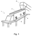
- FIG. 1 shows a vibrating screen 1 and partly a conveyor 2, by which the material to be screened can be fed onto the screen.
- the vibrating screen 1 comprises at least a screening element 3 and an aggregate 4 for moving the screening element.
- the screening element 3 is arranged in the frame, which is fitted with springs 5 in the supporting structures.
- the aggregate 4 that moves the screening element 3 can be implemented in a variety of ways, and some advantageous embodiments will be presented as follows.
- FIG. 2 shows a feeder 10 for feeding the material into the crusher.
- the feeder comprises at least a screening element 3 and an aggregate 4 for moving the screening element.
- the screening element 3 is fitted with springs 5 in the supporting structures of the feeder 10.
- the aggregate 4 comprises at least an aggregate frame 6, a shaft 7 having an axial line X and being arranged to rotate with respect to the aggregate frame, as well as a first element 8, that is, the first movable mass.
- the first element 8 is connected to the shaft 7 in such a way that the mass centre M8 of the element is not on the axial line X, and the element is arranged to move along a circular path.
- the aggregate 4 also comprises a second element 9, that is, the second movable mass, coupled to the shaft 7.
- the second element 9 is arranged to move back and forth along a linear path.
- the path of the second element 9 is substantially perpendicular to the axial line X. In this embodiment, the second element 9 is placed substantially inside the path of the first element 8.
- Figures 6 to 8 also show another embodiment.
- the most essential difference to the previous embodiment is the different implementation of the mass moving linearly back and forth.
- the second movable element 9 is placed substantially outside the path of the first element 8. This kind of an arrangement is advantageous, for example, when a large mass moving back and forth is needed for generating the desired movement.
- the second element 9 is formed in such a way that it also extends to the other side of the shaft 7 (for example above and below the shaft).
- the central line of the aggregate 4 is on the central line of the wall of the processing device in such a way that the parts of the first element 8 divided in two parts rotate on both sides of the central line, at an equal distance from the side wall of the processing device. Between these parts of the eccentric masses rotating on both sides, the second element 9 moves on the central line of the side wall of the processing device, the movement being effected by an eccentricity lathed in the driving shaft 7, on which the mass moving back and forth is mounted on bearings.
- the first element 8 is divided into two parts.
- the second element 9 can be formed of two or more parts.
- the first element 8 may be formed of one, two or more parts. In one embodiment, the first element 8 consists of a single part and the parts of the second element 9 are placed on both sides of the same.
- the eccentrically rotating mass that is, the first element 8 is used to generate a circular movement of the sprung processing device, such as the screen 1 or the feeder 10.
- the substantially elliptical movement is generated by coupling the eccentrically rotating mass 8 in the same phase as the mass moving back and forth, that is, the second element 9.
- the shape and the direction of the ellipse are preferably alterable.
- the shape of the ellipse can be altered by changing the ratio between the second element 9 and the first element 8, that is, between the mass moving back and forth and the rotating mass.
- the shape can also be influenced, inter alia , by changing the masses and/or the locations of the mass centres of the first element 8 and the second element 9.
- the shape of the ellipse can be changed by varying the travelling distance of the second element 9, that is, by varying the eccentricity of the bearing of the second element 9.
- the direction of the ellipse can be changed by turning the aggregate 4 in a desired direction with respect to the frame of the screen 1.
- the direction of rotation of the movement in turn, can be influenced by the direction of rotation of the shaft 7.
- Figures 9 and 10 show a solution for changing the eccentricity of the second element 9.
- the second element 9 is coupled to the shaft 7 by means of eccentric sleeves 91, 92.
- the first eccentric sleeve 91 is fitted to rotate in the hole of the second eccentric sleeve 92 when the shaft 7 is rotated.
- the hole of the first eccentric sleeve 91 that is, the hole of the shaft 7, is placed eccentrically.
- the first eccentric sleeve 91 generates a movement that comprises linear directions of movement.
- the hole in the second eccentric sleeve 92 is also placed eccentrically.
- the second eccentric sleeve 92 in the hole of the second element 9, it is possible to change the location of the hole of the shaft 7 with respect to the frame of the second element.
- the eccentric sleeve 91 can be replaced with an eccentricity formed in the shaft, as presented above in the embodiment of Fig. 3 .
- Figs. 9 and 10 can also be used to change the eccentricity of the first element 8, if necessary. If the element 8, 9 to be adjusted is divided into two or more parts, each part can be equipped with separate eccentric sleeves 91, 92.
- Figures 11 and 12 show some solutions for adjusting the mass of the element 8, 9.
- the element 8, 9 is provided with locations 11 for adjustable masses 12.
- Figure 12 presents another way of providing the element 8, 9 with adjustable masses.
- the element 8, 9 is provided with a connecting area 13 to which the adjustable masses 12 can be connected.
- the adjustable masses 12 also comprise a corresponding connecting area 13, in which case it is possible to couple several adjustable masses, if necessary.
- Adjustable masses 12 can be preferably added or removed as needed.
- the adjustable masses 12 can be used to influence the total mass and/or the mass centre of the element 8, 9 and thereby the movement generated by the aggregate 4.
- Figure 13 shows the principle of operation of a multi-step apparatus.
- the apparatus may be, for example, a screen and/or a feeder that comprises several individual screening and/or feeding elements.
- the feeder device comprises four screening elements 3.
- Each screening element 3 is equipped with a separate aggregate 4 for moving the screening element.
- the figure shows, in principle, the direction and magnitude of the path of each screening element 4 by ellipses 14.
- the ellipses 14 represent the paths by way of example, and they illustrate primarily the relationships between the paths of the different screening elements 3.
- the paths are affected in the above-presented ways, for example, by changing the masses and/or the mass centres of the first element 8 and the second element 9 in the aggregate 4.
- the shape of the path 14 can be changed by varying the travelling distance of the second element 9, that is, by varying the eccentricity of the bearing of the second element 9.
- the direction of the ellipse 14 can be changed by turning the aggregate 4 with respect to the frame of the screen 1.
- the first screening element 3 (on the left-hand side) is arranged to perform the greatest movement.
- the following screening elements perform a smaller movement in such a way that the path of the screening element on the right-hand side is the shortest.
- the paths of the different screening elements may also be different from those shown in the example, for the path of each screening element can be advantageously adjusted independently. The independent adjustment makes it possible to save power and to use the feeder device, the screening device or another processing device in an optimal way.
- the first element 8 was formed in such a way that the geometrical centre of the mass and the mass centre M8 are by the side of the axial line X. It is also possible to form the first element 8 in such a way that its geometrical centre is on the axial line X even if the mass centre M8 were not on the axial line.
- the first element 8 can be formed of a ring in which one sector has a greater mass than the rest of the ring.
- the shaft 7 can be rotated by a suitable actuator, such as, for example, an electrical motor or a hydraulic motor (not shown in the figures).
- the actuator may be coupled to the shaft 7 either directly or by means of suitable intermediate structures, such as gearings, clutches and/or belts.
- suitable intermediate structures such as gearings, clutches and/or belts.
- the actuator is coupled to the shaft 7 in such a way that the power is transmitted from the actuator to the shaft via an elastic clutch.
- FIG 14 shows a crushing plant which is suitable for the processing of mineral material, such as for the crushing of rock or the recirculation of construction material, such as for the processing of reinforced concrete.
- the crushing plant comprises a feeder 10 for feeding material to be crushed further to a screen 1, and to a crusher 15, such as a cone, gyratory, jaw, or centrifugal crusher.
- the crushing plant further comprises a side conveyor 16 and a main conveyor 17 as well as a power source 18 for driving the actuators, and a caterpillar drive 19 for moving the crushing plant.
- the crushing plant is a movable plant with a crusher mounted on a caterpillar drive.
- the crushing plant can also be moved by other means, such as wheels or legs, or it may be stationary.
Description
- The invention relates to the processing of mineral material, such as screens and feeders, and particularly aggregates used for moving vibrating screens and feeders.
- Vibrating screens are used, for example, in crushing plants for sorting material into different classes according to the particle size. A screen comprises a screening element, which may be, for example, a sieve, a mesh or a grate, whose openings are passed by pieces of the material to be screened which are smaller than a given fraction size. The screen may comprise several screening elements, which may be placed, for example, on top of each other. Advantageously, all the screening elements of the screen are moved by joint aggregates. E.g. the publication
WO 02/00359 - There is also so called "directional-action mechanical vibrator" that can be used for moving a screening element. In this kind of solution there is two or more moving masses but these are usually used for balancing each other and the vibration is formed mechanically i.e. not by means of the inertia forces caused by movement of the masses. This type of vibrator is described in publication
US 4,287,779 . - Feeders as well as vibrating screens are used in crushing plants for the purpose of sorting the material, and feeders are also used for feeding the material to be crushed into the crusher. In the feeder, the smaller fraction that should not to be fed into the crusher, is separated out. With respect to its function, the feeder resembles the vibrating screen.
- In solutions of prior art wherein the elliptical movement path is generated by means of the inertia forces, two or more drive shafts are needed for rotating eccentrically rotating masses. The shafts must be synchronized by means of a gearing or cogged belts, which makes the structure complex.
- The aim of the arrangement according to the invention is to provide a solution for forming the elliptical path of the mineral material processing apparatus, such as, for example, a screen or a feeder, in a way which is simpler than in prior art.
- To achieve this aim, the vibrating aggregate according to the invention is primarily characterized in what will be presented in the
independent claim 1. The processing apparatus according to the invention, in turn, is primarily characterized in what will be presented in theindependent claim 7. The method according to the invention is, in turn, primarily characterized in what will be presented in theindependent claim 12. The other, dependent claims will present some preferred embodiments of the invention. - The basic idea of the invention is that the elliptical movement of the mineral material processing device, such as, for example, a screen or a feeder, is generated by a single rotatable shaft.
- According to the basic idea, the apparatus for processing mineral material comprises at least a processing device and a vibrating aggregate for moving the processing device, the vibrating aggregate comprising at least a frame, a shaft having an axial line and being arranged to rotate with respect to the frame, as well as a first element connected to the shaft in such a way that the centre of mass of the element is not on the axial line, and fitted to move along a circular path. Furthermore, the vibrating aggregate comprises a second element coupled to the shaft and arranged to move along a linear path. Preferably, the vibrating aggregate is arranged to move the processing device along an elliptical path.
- In the method according to the basic idea, the processing device of the apparatus for processing mineral material is moved along an elliptical path, in which method a part of the movement of the processing device is generated by a first element connected to the rotatable shaft, the centre of mass of the first element being not on the axial line of the shaft, and the first element moving along a circular path when the shaft is moving. Furthermore, a part of the movement of the processing device is generated by a second element connected to the same rotatable shaft, which second element moves along a linear path when the shaft is moving.
- In an advantageous embodiment, the path of the second element is perpendicular to the axial line. In one embodiment, the second element is coupled to the shaft in an eccentric way.
- In one embodiment, the first element is divided into two parts, which parts are placed in parallel with the axial line on different sides of the second element.
- Various advantages are achieved with the different embodiments of the invention. First of all, the elliptical movement of the processing device is generated by a single shaft. Moreover, the ellipticity and direction of the ellipse can be easily adjusted in some embodiments. In one embodiment, the movable masses and bearings are placed close to each other and symmetrically with respect to the side wall of the processing device.
- In the following, the invention will be described in more detail with reference to the appended principle drawings, in which
- Fig. 1
- illustrates the principle of the assembly of the screen device;
- Fig. 2
- illustrates the principle of the assembly of the feeder device;
- Fig. 3
- shows a cross-sectional view of one embodiment of the aggregate along the axial line,
- Fig. 4
- shows a cross-section of the embodiment according to
Fig. 3 in plane A-A, - Fig. 5
- shows a cross-section of the embodiment according to
Fig. 3 in plane B-B, - Fig. 6
- shows a cross-sectional view of one embodiment of the aggregate along the axial line,
- Fig. 7
- shows a cross-section of the embodiment according to
Fig. 6 in plane A-A, - Fig. 8
- shows a cross-section of the embodiment according to
Fig. 6 in plane B-B, - Fig. 9
- shows a solution for adjusting the eccentricity of the aggregate;
- Fig. 10
- shows a cross-section of the embodiment according to
Fig. 9 in plane C-C, - Fig. 11
- shows an arrangement for adjusting the movable mass of the aggregate;
- Fig. 12
- shows another arrangement for adjusting the movable mass of the aggregate;
- Fig. 13
- illustrates the principle of a multi-step feeder apparatus;
- Fig. 14
- shows an apparatus for processing mineral material.
- For the sake of clarity, the drawings only show the details necessary for understanding the invention. The structures and details that are not necessary for understanding the invention but are obvious for anyone skilled in the art have been omitted from the figures in order to emphasize the characteristics of the invention. Furthermore, the dimensions of the figures do not necessarily correspond to the reality, but the aim of the figures is to illustrate the principle of the arrangement by selecting the dimensions in a way that is appropriate for the representation.
-
Figure 1 shows a vibratingscreen 1 and partly aconveyor 2, by which the material to be screened can be fed onto the screen. The vibratingscreen 1 comprises at least ascreening element 3 and anaggregate 4 for moving the screening element. Thescreening element 3 is arranged in the frame, which is fitted withsprings 5 in the supporting structures. Theaggregate 4 that moves thescreening element 3 can be implemented in a variety of ways, and some advantageous embodiments will be presented as follows. -
Figure 2 shows afeeder 10 for feeding the material into the crusher. The feeder comprises at least ascreening element 3 and anaggregate 4 for moving the screening element. Thescreening element 3 is fitted withsprings 5 in the supporting structures of thefeeder 10. - The
aggregate 4 according toFigs. 3 to 5 comprises at least anaggregate frame 6, ashaft 7 having an axial line X and being arranged to rotate with respect to the aggregate frame, as well as afirst element 8, that is, the first movable mass. Thefirst element 8 is connected to theshaft 7 in such a way that the mass centre M8 of the element is not on the axial line X, and the element is arranged to move along a circular path. Theaggregate 4 also comprises asecond element 9, that is, the second movable mass, coupled to theshaft 7. Thesecond element 9 is arranged to move back and forth along a linear path. The path of thesecond element 9 is substantially perpendicular to the axial line X. In this embodiment, thesecond element 9 is placed substantially inside the path of thefirst element 8. -
Figures 6 to 8 also show another embodiment. The most essential difference to the previous embodiment is the different implementation of the mass moving linearly back and forth. The secondmovable element 9 is placed substantially outside the path of thefirst element 8. This kind of an arrangement is advantageous, for example, when a large mass moving back and forth is needed for generating the desired movement. - In an embodiment in which a large second mass moving back and forth is needed, the
second element 9 is formed in such a way that it also extends to the other side of the shaft 7 (for example above and below the shaft). - In the examples shown in
Figs. 3 and6 , the central line of theaggregate 4 is on the central line of the wall of the processing device in such a way that the parts of thefirst element 8 divided in two parts rotate on both sides of the central line, at an equal distance from the side wall of the processing device. Between these parts of the eccentric masses rotating on both sides, thesecond element 9 moves on the central line of the side wall of the processing device, the movement being effected by an eccentricity lathed in the drivingshaft 7, on which the mass moving back and forth is mounted on bearings. In the preceding examples, thefirst element 8 is divided into two parts. It is also possible to implement theaggregate 4 in another way. For example, thesecond element 9 can be formed of two or more parts. Also, thefirst element 8 may be formed of one, two or more parts. In one embodiment, thefirst element 8 consists of a single part and the parts of thesecond element 9 are placed on both sides of the same. - The eccentrically rotating mass, that is, the
first element 8, is used to generate a circular movement of the sprung processing device, such as thescreen 1 or thefeeder 10. Normally, an advantageous movement of the processing device is substantially elliptical. In the presented solutions, the substantially elliptical movement is generated by coupling the eccentricallyrotating mass 8 in the same phase as the mass moving back and forth, that is, thesecond element 9. The shape and the direction of the ellipse are preferably alterable. - The shape of the ellipse can be altered by changing the ratio between the
second element 9 and thefirst element 8, that is, between the mass moving back and forth and the rotating mass. The shape can also be influenced, inter alia, by changing the masses and/or the locations of the mass centres of thefirst element 8 and thesecond element 9. Furthermore, the shape of the ellipse can be changed by varying the travelling distance of thesecond element 9, that is, by varying the eccentricity of the bearing of thesecond element 9. The direction of the ellipse can be changed by turning theaggregate 4 in a desired direction with respect to the frame of thescreen 1. The direction of rotation of the movement, in turn, can be influenced by the direction of rotation of theshaft 7. -
Figures 9 and 10 show a solution for changing the eccentricity of thesecond element 9. Thesecond element 9 is coupled to theshaft 7 by means ofeccentric sleeves eccentric sleeve 91 is fitted to rotate in the hole of the secondeccentric sleeve 92 when theshaft 7 is rotated. As can be seen fromFig. 10 , the hole of the firsteccentric sleeve 91, that is, the hole of theshaft 7, is placed eccentrically. Thus, when theshaft 7 rotates, the firsteccentric sleeve 91 generates a movement that comprises linear directions of movement. The hole in the secondeccentric sleeve 92 is also placed eccentrically. Thus, by turning the secondeccentric sleeve 92 in the hole of thesecond element 9, it is possible to change the location of the hole of theshaft 7 with respect to the frame of the second element. There may also be more than two eccentric sleeves. Alternatively, theeccentric sleeve 91 can be replaced with an eccentricity formed in the shaft, as presented above in the embodiment ofFig. 3 . - The arrangement of adjustment shown in
Figs. 9 and 10 can also be used to change the eccentricity of thefirst element 8, if necessary. If theelement eccentric sleeves -
Figures 11 and 12 show some solutions for adjusting the mass of theelement Fig. 11 , theelement locations 11 foradjustable masses 12.Figure 12 , in turn, presents another way of providing theelement element area 13 to which theadjustable masses 12 can be connected. Advantageously, theadjustable masses 12 also comprise a corresponding connectingarea 13, in which case it is possible to couple several adjustable masses, if necessary.Adjustable masses 12 can be preferably added or removed as needed. Theadjustable masses 12 can be used to influence the total mass and/or the mass centre of theelement aggregate 4. -
Figure 13 shows the principle of operation of a multi-step apparatus. The apparatus may be, for example, a screen and/or a feeder that comprises several individual screening and/or feeding elements. In the example, the feeder device comprises fourscreening elements 3. Eachscreening element 3 is equipped with aseparate aggregate 4 for moving the screening element. The figure shows, in principle, the direction and magnitude of the path of eachscreening element 4 byellipses 14. Theellipses 14 represent the paths by way of example, and they illustrate primarily the relationships between the paths of thedifferent screening elements 3. The paths are affected in the above-presented ways, for example, by changing the masses and/or the mass centres of thefirst element 8 and thesecond element 9 in theaggregate 4. Furthermore, the shape of thepath 14 can be changed by varying the travelling distance of thesecond element 9, that is, by varying the eccentricity of the bearing of thesecond element 9. The direction of theellipse 14 can be changed by turning theaggregate 4 with respect to the frame of thescreen 1. In the example, the first screening element 3 (on the left-hand side) is arranged to perform the greatest movement. Thus, the material to be fed moves strongly, and the desired fractions can be effectively removed from it. The following screening elements perform a smaller movement in such a way that the path of the screening element on the right-hand side is the shortest. The paths of the different screening elements may also be different from those shown in the example, for the path of each screening element can be advantageously adjusted independently. The independent adjustment makes it possible to save power and to use the feeder device, the screening device or another processing device in an optimal way. - The basic principle of the novel arrangement relating to the processing of mineral material was presented above. Some details, such as, for example, the bearings, the lubrication, the compensation of wearing, the adjustment of the masses, the mountings, etc., can be implemented in ways not shown in the examples.
- In the examples, the
first element 8 was formed in such a way that the geometrical centre of the mass and the mass centre M8 are by the side of the axial line X. It is also possible to form thefirst element 8 in such a way that its geometrical centre is on the axial line X even if the mass centre M8 were not on the axial line. For example, thefirst element 8 can be formed of a ring in which one sector has a greater mass than the rest of the ring. - The
shaft 7 can be rotated by a suitable actuator, such as, for example, an electrical motor or a hydraulic motor (not shown in the figures). The actuator may be coupled to theshaft 7 either directly or by means of suitable intermediate structures, such as gearings, clutches and/or belts. Preferably, the actuator is coupled to theshaft 7 in such a way that the power is transmitted from the actuator to the shaft via an elastic clutch. - In one embodiment, on both sides of the processing device, there are
aggregates 4 coupled to each other by the shaft and elastic clutches. -
Figure 14 shows a crushing plant which is suitable for the processing of mineral material, such as for the crushing of rock or the recirculation of construction material, such as for the processing of reinforced concrete. The crushing plant comprises afeeder 10 for feeding material to be crushed further to ascreen 1, and to acrusher 15, such as a cone, gyratory, jaw, or centrifugal crusher. The crushing plant further comprises aside conveyor 16 and amain conveyor 17 as well as apower source 18 for driving the actuators, and acaterpillar drive 19 for moving the crushing plant. - In the example, the crushing plant is a movable plant with a crusher mounted on a caterpillar drive. The crushing plant can also be moved by other means, such as wheels or legs, or it may be stationary.
- By combining, in various ways, the modes and structures disclosed in connection with the different embodiments of the invention presented above, it is possible to produce various embodiments of the invention in accordance with the claims. Therefore, the above-presented examples must not be interpreted to restrict the invention, but the embodiments of the invention may be freely varied within the scope of the inventive features presented in the claims hereinbelow.
Claims (15)
- A vibratory aggregate (4) for an apparatus for processing mineral material (1), the vibratory aggregate (4) comprising at least- a frame (6),- a shaft (7) having an axial line (X) and being arranged to rotate with respect to the frame (6),- a first element (8) coupled to the shaft (7) in such a way that the mass centre (M8) of the element is not on the axial line (X), and arranged to move along a circular path,- a second element (9) coupled to the shaft (7) and fitted to move along a linear path,characterized in that the vibratory aggregate comprises means (11-13, 91, 92) for adjusting the phase of the movement of the first element (8) in relation to the phase of the movement of the second element (9) such that an elliptical movement of the vibratory aggregate (4) is generated when the shaft (7) is rotated.
- The aggregate (4) according to claim 1, characterized in that the path of the second element (9) is perpendicular to the axial line (X).
- The aggregate (4) according to claim 1 or 2, characterized in that the second element (9) is eccentrically coupled to the shaft (7).
- The aggregate (4) according to any of the preceding claims, characterized in that the first element (8) is divided into two parts, which parts are placed in parallel with the axial line (X) on different sides of the second element (9).
- The aggregate (4) according to any of the preceding claims, characterized in that the aggregate (4) comprises means (12) for changing the relationship between the masses of the first element and the second element.
- The aggregate (4) according to any of the preceding claims, characterized in that the aggregate (4) comprises means (91, 92) for changing the travel distance of the mass of the second element (9).
- An apparatus for processing mineral material, comprising at least a processing device (1) and a vibrating aggregate (4) for moving the processing device (1), the vibrating aggregate (4) comprising at least- a frame (6),- a shaft (7) having an axial line (X) and being arranged to rotate with respect to the frame (6),- a first element (8) coupled to the shaft (7) in such a way that the mass centre (M8) of the element is not on the axial line (X), and arranged to move along a circular path,- a second element (9) coupled to the shaft and fitted to move along a linear path,characterized in that the apparatus comprises means (11-13, 91, 92) for adjusting the phase of the movement of the first element (8) in relation to the phase of the movement of the second element (9) such that an elliptical movement of the vibratory aggregate (4) is generated when the shaft (7) is rotated.
- The processing apparatus according to claim 7, characterized in that the aggregate (4) is arranged to move the processing device (1) along an elliptical path.
- The processing apparatus according to claim 8, characterized in that the path of the second element (9) is perpendicular to the axial line (X).
- The processing apparatus according to any of the preceding claims 8 or 9, characterized in that the second element (9) is eccentrically coupled to the shaft (7).
- The processing apparatus according to any of the preceding claims 8 to 10, characterized in that the processing apparatus is one of the following: a feeder, a screen, a stationary crushing plant, a movable crushing plant.
- A method for moving the processing device (1) of a mineral material processing apparatus along an elliptical path, in which method- a part of the movement of the processing device is generated by a first element (8) connected to a rotatable shaft (7), the centre of mass (M8) of the first element (8) being not on the axial line (X) of the shaft (7), and the first element (8) moving along a circular path when the shaft (7) is moving- an another part of the movement of the processing device is generated by a second element (9) connected to the same rotatable shaft (7), which second element (9) moves along a linear path when the shaft (7) is moving,characterized in that the phase of the movement of the first element (8) in relation to the phase of the movement of the second element (9) is adjusted such that an elliptical movement of the vibratory aggregate (4) is generated when the shaft (7) is rotated.
- The method according to claim 12, characterized in that the second element (9) moves in a direction perpendicular to the axial line (X).
- The method according to claim 12 or 13, characterized in that the shape of the elliptical path generated by the aggregate (4) is adjusted by changing the relationship between the masses of the rotating first element (8) and the second element (9) moving linearly.
- The method according to any of the preceding claims 12 to 14, characterized in that the shape of the elliptical path generated by the aggregate (4) is adjusted by changing the travel distance of the mass of the second element (9) moving linearly.
Applications Claiming Priority (1)
| Application Number | Priority Date | Filing Date | Title |
|---|---|---|---|
| PCT/FI2008/050398 WO2010000911A1 (en) | 2008-06-30 | 2008-06-30 | A vibrating aggregate, an apparatus for processing mineral material, and a method for moving a processing device of an apparatus for processing mineral material |
Publications (2)
| Publication Number | Publication Date |
|---|---|
| EP2318153A1 EP2318153A1 (en) | 2011-05-11 |
| EP2318153B1 true EP2318153B1 (en) | 2012-09-26 |
Family
ID=40377346
Family Applications (1)
| Application Number | Title | Priority Date | Filing Date |
|---|---|---|---|
| EP08775523A Active EP2318153B1 (en) | 2008-06-30 | 2008-06-30 | A vibrating aggregate, an apparatus for processing mineral material, and a method for moving a processing device of an apparatus for processing mineral material |
Country Status (4)
| Country | Link |
|---|---|
| US (1) | US9339847B2 (en) |
| EP (1) | EP2318153B1 (en) |
| CN (1) | CN102076429B (en) |
| WO (1) | WO2010000911A1 (en) |
Families Citing this family (3)
| Publication number | Priority date | Publication date | Assignee | Title |
|---|---|---|---|---|
| CN101897365B (en) * | 2010-07-30 | 2012-02-01 | 四川中测量仪科技有限公司 | Tea sifting and grading machine and tea sifting and grading machine group |
| WO2018210431A1 (en) * | 2017-05-19 | 2018-11-22 | Metso Sweden Ab | Ultrasonic detection system and method |
| FR3067486B1 (en) | 2017-06-09 | 2021-08-27 | Cryptosense | NON-INTRUSIVE DETECTION PROCESS FOR SECURITY BREAKS OF A COMPUTER PROGRAM |
Family Cites Families (25)
| Publication number | Priority date | Publication date | Assignee | Title |
|---|---|---|---|---|
| US756950A (en) * | 1903-01-05 | 1904-04-12 | John Fraser | Driving mechanism for sieve bolting-machines. |
| US1654815A (en) * | 1924-10-03 | 1928-01-03 | Naeher | Agitator |
| US1836757A (en) * | 1926-07-01 | 1931-12-15 | Sulzer Ag | Power transmission mechanism |
| US2008296A (en) * | 1927-06-20 | 1935-07-16 | Productive Equipment Corp | Motion converting mechanism |
| DE732979C (en) * | 1937-12-01 | 1943-03-17 | Hans Held | Device on sieve or conveyor devices to regulate the oscillation path |
| US2367070A (en) * | 1941-01-10 | 1945-01-09 | Nordberg Manufacturing Co | Power plant for vibrating screens |
| US2334973A (en) * | 1941-08-11 | 1943-11-23 | Marvin E Whiteman | Tamping roller |
| CH251734A (en) * | 1945-10-23 | 1947-11-15 | Baetschmann Eugen | Vibrators for screens and conveyor systems. |
| US2561344A (en) * | 1948-12-17 | 1951-07-24 | United Shoe Machinery Corp | Variable displacement drive |
| US2622444A (en) * | 1951-04-10 | 1952-12-23 | Waldvogel Hans | Vibrating appliance |
| US3026781A (en) * | 1956-06-01 | 1962-03-27 | Scheid Maschinenfabrik Gmbh | Road roller |
| US2901111A (en) * | 1956-07-24 | 1959-08-25 | Buchler Geb | Vibrator chute |
| US3039609A (en) * | 1959-07-06 | 1962-06-19 | Hewitt Robins Inc | Positive motion horizontal screen shaft assembly |
| AT303802B (en) * | 1968-04-19 | 1972-12-11 | Abg Werke Gmbh | Vibrating roller with eccentric masses to generate balancing forces |
| US3768647A (en) * | 1971-06-11 | 1973-10-30 | Partec Inc | Vibrating screening apparatus |
| ES414348A1 (en) * | 1973-05-03 | 1976-02-01 | Lebrero Martinez | Vibrating roller |
| US4237000A (en) * | 1979-03-05 | 1980-12-02 | F. T. Read & Sons, Inc. | Shaker assembly for screening and scalping |
| DE2927241C2 (en) * | 1979-07-05 | 1983-04-21 | Ukrainskij naučno-issledovatel'skij institut mechanizacii i elektrifikacii sel'skogo chozjajstva, Glevacha, Kievskaja oblast' | Mechanical vibrator with directional effect |
| US4617832A (en) * | 1982-09-20 | 1986-10-21 | General Kinematics | Vibratory apparatus having variable lead angle and force |
| CN2172161Y (en) | 1993-10-22 | 1994-07-20 | 西南石油学院 | Vibrating sifter vibration exciter |
| SE514777C2 (en) * | 1998-07-13 | 2001-04-23 | Rune Sturesson | Rotary eccentric device for continuous adjustment of the vibration amplitude |
| CN2384692Y (en) | 1999-08-09 | 2000-06-28 | 西南石油学院 | Double-shaft translation elliptic shaking sieve |
| DE10031617A1 (en) * | 2000-06-29 | 2002-01-17 | Wacker Werke Kg | Vibration exciter with amplitude adjustment |
| CN2465821Y (en) | 2001-01-03 | 2001-12-19 | 西南石油学院 | Changeable ellipse and changeable straight line vibration type vibration screen |
| CN201015764Y (en) | 2007-03-12 | 2008-02-06 | 朱满平 | Thin materials screener with the track adjustable |
-
2008
- 2008-06-30 WO PCT/FI2008/050398 patent/WO2010000911A1/en active Application Filing
- 2008-06-30 EP EP08775523A patent/EP2318153B1/en active Active
- 2008-06-30 CN CN200880130105.1A patent/CN102076429B/en active Active
- 2008-06-30 US US12/996,528 patent/US9339847B2/en active Active
Also Published As
| Publication number | Publication date |
|---|---|
| WO2010000911A1 (en) | 2010-01-07 |
| EP2318153A1 (en) | 2011-05-11 |
| US9339847B2 (en) | 2016-05-17 |
| CN102076429A (en) | 2011-05-25 |
| CN102076429B (en) | 2014-07-23 |
| US20110072917A1 (en) | 2011-03-31 |
Similar Documents
| Publication | Publication Date | Title |
|---|---|---|
| EP2155394B1 (en) | Crusher, method for crushing material and method for controlling a crusher | |
| CA3022912C (en) | Adjustable split weight gyratory sifter | |
| EP2907589B1 (en) | Material screening apparatus with multi-mode screen box | |
| EP3077128B1 (en) | Vibratory apparatus with dynamic balancer and balancing method | |
| EP3520909B1 (en) | Vibration generating mechanism for a vibrating screen box | |
| EP2581140B1 (en) | Method and device for screening materials, such as aggregates and/or soils | |
| EP2318153B1 (en) | A vibrating aggregate, an apparatus for processing mineral material, and a method for moving a processing device of an apparatus for processing mineral material | |
| GB2505483A (en) | Vibratory screen layered sidewall | |
| US20150353290A1 (en) | Vibrating equipment and metod of processing material | |
| JP2010240553A (en) | Vibration generator | |
| CN116390817A (en) | Vibration screening control device | |
| KR102615372B1 (en) | Vibration generator capable of adjusting amplitude of vibration sorting screen | |
| KR100421942B1 (en) | Variable vibrating device of apparatus for screening construction wastes | |
| KR101805969B1 (en) | Method and device for fractionating bulk material | |
| CN103909060A (en) | Self-synchronizing translation elliptical vibrating screen with three shock excitation motors | |
| EP3842158A1 (en) | Vibrating screen, especially with slotted sieve, and method for controlling the operation of the screen, especially with slotted sieve | |
| CN214918109U (en) | Double-crankshaft vibration structure | |
| KR101466640B1 (en) | Vibrator | |
| CN107716282A (en) | It is a kind of with the vibratory sieve vibrated in high precision | |
| CN114377948B (en) | Modular reconfigurable transverse vibration large-scale flip-flow screen | |
| JP2002119918A (en) | Supporting device for vibrating grid | |
| WO2021152206A1 (en) | Vibrating arrangement | |
| JP2017006825A (en) | Incombustible fine separation device | |
| CN102513286A (en) | Uniaxial elliptic motion trail vibration exciter | |
| RU2077394C1 (en) | Crusher with vibratory screen |
Legal Events
| Date | Code | Title | Description |
|---|---|---|---|
| PUAI | Public reference made under article 153(3) epc to a published international application that has entered the european phase |
Free format text: ORIGINAL CODE: 0009012 |
|
| 17P | Request for examination filed |
Effective date: 20110110 |
|
| AK | Designated contracting states |
Kind code of ref document: A1 Designated state(s): AT BE BG CH CY CZ DE DK EE ES FI FR GB GR HR HU IE IS IT LI LT LU LV MC MT NL NO PL PT RO SE SI SK TR |
|
| AX | Request for extension of the european patent |
Extension state: AL BA MK RS |
|
| DAX | Request for extension of the european patent (deleted) | ||
| GRAP | Despatch of communication of intention to grant a patent |
Free format text: ORIGINAL CODE: EPIDOSNIGR1 |
|
| GRAS | Grant fee paid |
Free format text: ORIGINAL CODE: EPIDOSNIGR3 |
|
| GRAA | (expected) grant |
Free format text: ORIGINAL CODE: 0009210 |
|
| AK | Designated contracting states |
Kind code of ref document: B1 Designated state(s): AT BE BG CH CY CZ DE DK EE ES FI FR GB GR HR HU IE IS IT LI LT LU LV MC MT NL NO PL PT RO SE SI SK TR |
|
| REG | Reference to a national code |
Ref country code: GB Ref legal event code: FG4D |
|
| REG | Reference to a national code |
Ref country code: CH Ref legal event code: EP |
|
| REG | Reference to a national code |
Ref country code: AT Ref legal event code: REF Ref document number: 576768 Country of ref document: AT Kind code of ref document: T Effective date: 20121015 |
|
| REG | Reference to a national code |
Ref country code: IE Ref legal event code: FG4D |
|
| REG | Reference to a national code |
Ref country code: DE Ref legal event code: R096 Ref document number: 602008019033 Country of ref document: DE Effective date: 20121129 |
|
| REG | Reference to a national code |
Ref country code: SE Ref legal event code: TRGR |
|
| PG25 | Lapsed in a contracting state [announced via postgrant information from national office to epo] |
Ref country code: LT Free format text: LAPSE BECAUSE OF FAILURE TO SUBMIT A TRANSLATION OF THE DESCRIPTION OR TO PAY THE FEE WITHIN THE PRESCRIBED TIME-LIMIT Effective date: 20120926 Ref country code: NO Free format text: LAPSE BECAUSE OF FAILURE TO SUBMIT A TRANSLATION OF THE DESCRIPTION OR TO PAY THE FEE WITHIN THE PRESCRIBED TIME-LIMIT Effective date: 20121226 Ref country code: HR Free format text: LAPSE BECAUSE OF FAILURE TO SUBMIT A TRANSLATION OF THE DESCRIPTION OR TO PAY THE FEE WITHIN THE PRESCRIBED TIME-LIMIT Effective date: 20120926 Ref country code: FI Free format text: LAPSE BECAUSE OF FAILURE TO SUBMIT A TRANSLATION OF THE DESCRIPTION OR TO PAY THE FEE WITHIN THE PRESCRIBED TIME-LIMIT Effective date: 20120926 |
|
| REG | Reference to a national code |
Ref country code: AT Ref legal event code: MK05 Ref document number: 576768 Country of ref document: AT Kind code of ref document: T Effective date: 20120926 |
|
| REG | Reference to a national code |
Ref country code: LT Ref legal event code: MG4D Effective date: 20120926 |
|
| REG | Reference to a national code |
Ref country code: NL Ref legal event code: VDEP Effective date: 20120926 |
|
| PG25 | Lapsed in a contracting state [announced via postgrant information from national office to epo] |
Ref country code: SI Free format text: LAPSE BECAUSE OF FAILURE TO SUBMIT A TRANSLATION OF THE DESCRIPTION OR TO PAY THE FEE WITHIN THE PRESCRIBED TIME-LIMIT Effective date: 20120926 Ref country code: GR Free format text: LAPSE BECAUSE OF FAILURE TO SUBMIT A TRANSLATION OF THE DESCRIPTION OR TO PAY THE FEE WITHIN THE PRESCRIBED TIME-LIMIT Effective date: 20121227 Ref country code: LV Free format text: LAPSE BECAUSE OF FAILURE TO SUBMIT A TRANSLATION OF THE DESCRIPTION OR TO PAY THE FEE WITHIN THE PRESCRIBED TIME-LIMIT Effective date: 20120926 |
|
| PG25 | Lapsed in a contracting state [announced via postgrant information from national office to epo] |
Ref country code: ES Free format text: LAPSE BECAUSE OF FAILURE TO SUBMIT A TRANSLATION OF THE DESCRIPTION OR TO PAY THE FEE WITHIN THE PRESCRIBED TIME-LIMIT Effective date: 20130106 Ref country code: CZ Free format text: LAPSE BECAUSE OF FAILURE TO SUBMIT A TRANSLATION OF THE DESCRIPTION OR TO PAY THE FEE WITHIN THE PRESCRIBED TIME-LIMIT Effective date: 20120926 Ref country code: NL Free format text: LAPSE BECAUSE OF FAILURE TO SUBMIT A TRANSLATION OF THE DESCRIPTION OR TO PAY THE FEE WITHIN THE PRESCRIBED TIME-LIMIT Effective date: 20120926 Ref country code: IS Free format text: LAPSE BECAUSE OF FAILURE TO SUBMIT A TRANSLATION OF THE DESCRIPTION OR TO PAY THE FEE WITHIN THE PRESCRIBED TIME-LIMIT Effective date: 20130126 Ref country code: BE Free format text: LAPSE BECAUSE OF FAILURE TO SUBMIT A TRANSLATION OF THE DESCRIPTION OR TO PAY THE FEE WITHIN THE PRESCRIBED TIME-LIMIT Effective date: 20120926 Ref country code: RO Free format text: LAPSE BECAUSE OF FAILURE TO SUBMIT A TRANSLATION OF THE DESCRIPTION OR TO PAY THE FEE WITHIN THE PRESCRIBED TIME-LIMIT Effective date: 20120926 Ref country code: EE Free format text: LAPSE BECAUSE OF FAILURE TO SUBMIT A TRANSLATION OF THE DESCRIPTION OR TO PAY THE FEE WITHIN THE PRESCRIBED TIME-LIMIT Effective date: 20120926 |
|
| PG25 | Lapsed in a contracting state [announced via postgrant information from national office to epo] |
Ref country code: PL Free format text: LAPSE BECAUSE OF FAILURE TO SUBMIT A TRANSLATION OF THE DESCRIPTION OR TO PAY THE FEE WITHIN THE PRESCRIBED TIME-LIMIT Effective date: 20120926 Ref country code: SK Free format text: LAPSE BECAUSE OF FAILURE TO SUBMIT A TRANSLATION OF THE DESCRIPTION OR TO PAY THE FEE WITHIN THE PRESCRIBED TIME-LIMIT Effective date: 20120926 Ref country code: PT Free format text: LAPSE BECAUSE OF FAILURE TO SUBMIT A TRANSLATION OF THE DESCRIPTION OR TO PAY THE FEE WITHIN THE PRESCRIBED TIME-LIMIT Effective date: 20130128 |
|
| PG25 | Lapsed in a contracting state [announced via postgrant information from national office to epo] |
Ref country code: AT Free format text: LAPSE BECAUSE OF FAILURE TO SUBMIT A TRANSLATION OF THE DESCRIPTION OR TO PAY THE FEE WITHIN THE PRESCRIBED TIME-LIMIT Effective date: 20120926 |
|
| PG25 | Lapsed in a contracting state [announced via postgrant information from national office to epo] |
Ref country code: DK Free format text: LAPSE BECAUSE OF FAILURE TO SUBMIT A TRANSLATION OF THE DESCRIPTION OR TO PAY THE FEE WITHIN THE PRESCRIBED TIME-LIMIT Effective date: 20120926 Ref country code: BG Free format text: LAPSE BECAUSE OF FAILURE TO SUBMIT A TRANSLATION OF THE DESCRIPTION OR TO PAY THE FEE WITHIN THE PRESCRIBED TIME-LIMIT Effective date: 20121226 |
|
| PLBE | No opposition filed within time limit |
Free format text: ORIGINAL CODE: 0009261 |
|
| STAA | Information on the status of an ep patent application or granted ep patent |
Free format text: STATUS: NO OPPOSITION FILED WITHIN TIME LIMIT |
|
| PG25 | Lapsed in a contracting state [announced via postgrant information from national office to epo] |
Ref country code: IT Free format text: LAPSE BECAUSE OF FAILURE TO SUBMIT A TRANSLATION OF THE DESCRIPTION OR TO PAY THE FEE WITHIN THE PRESCRIBED TIME-LIMIT Effective date: 20120926 |
|
| 26N | No opposition filed |
Effective date: 20130627 |
|
| REG | Reference to a national code |
Ref country code: DE Ref legal event code: R097 Ref document number: 602008019033 Country of ref document: DE Effective date: 20130627 |
|
| PG25 | Lapsed in a contracting state [announced via postgrant information from national office to epo] |
Ref country code: CY Free format text: LAPSE BECAUSE OF FAILURE TO SUBMIT A TRANSLATION OF THE DESCRIPTION OR TO PAY THE FEE WITHIN THE PRESCRIBED TIME-LIMIT Effective date: 20120926 |
|
| PG25 | Lapsed in a contracting state [announced via postgrant information from national office to epo] |
Ref country code: MC Free format text: LAPSE BECAUSE OF FAILURE TO SUBMIT A TRANSLATION OF THE DESCRIPTION OR TO PAY THE FEE WITHIN THE PRESCRIBED TIME-LIMIT Effective date: 20120926 |
|
| REG | Reference to a national code |
Ref country code: CH Ref legal event code: PL |
|
| REG | Reference to a national code |
Ref country code: IE Ref legal event code: MM4A |
|
| PG25 | Lapsed in a contracting state [announced via postgrant information from national office to epo] |
Ref country code: IE Free format text: LAPSE BECAUSE OF NON-PAYMENT OF DUE FEES Effective date: 20130630 Ref country code: LI Free format text: LAPSE BECAUSE OF NON-PAYMENT OF DUE FEES Effective date: 20130630 Ref country code: CH Free format text: LAPSE BECAUSE OF NON-PAYMENT OF DUE FEES Effective date: 20130630 |
|
| PG25 | Lapsed in a contracting state [announced via postgrant information from national office to epo] |
Ref country code: MT Free format text: LAPSE BECAUSE OF FAILURE TO SUBMIT A TRANSLATION OF THE DESCRIPTION OR TO PAY THE FEE WITHIN THE PRESCRIBED TIME-LIMIT Effective date: 20120926 |
|
| PG25 | Lapsed in a contracting state [announced via postgrant information from national office to epo] |
Ref country code: HU Free format text: LAPSE BECAUSE OF FAILURE TO SUBMIT A TRANSLATION OF THE DESCRIPTION OR TO PAY THE FEE WITHIN THE PRESCRIBED TIME-LIMIT; INVALID AB INITIO Effective date: 20080630 Ref country code: LU Free format text: LAPSE BECAUSE OF NON-PAYMENT OF DUE FEES Effective date: 20130630 |
|
| REG | Reference to a national code |
Ref country code: DE Ref legal event code: R082 Ref document number: 602008019033 Country of ref document: DE Representative=s name: GRAMM, LINS & PARTNER PATENT- UND RECHTSANWAEL, DE |
|
| REG | Reference to a national code |
Ref country code: FR Ref legal event code: PLFP Year of fee payment: 9 |
|
| REG | Reference to a national code |
Ref country code: FR Ref legal event code: PLFP Year of fee payment: 10 |
|
| REG | Reference to a national code |
Ref country code: FR Ref legal event code: PLFP Year of fee payment: 11 |
|
| REG | Reference to a national code |
Ref country code: DE Ref legal event code: R081 Ref document number: 602008019033 Country of ref document: DE Owner name: METSO OUTOTEC FINLAND OY, FI Free format text: FORMER OWNER: METSO MINERALS, INC., HELSINKI, FI Ref country code: DE Ref legal event code: R082 Ref document number: 602008019033 Country of ref document: DE Representative=s name: HOFFMANN - EITLE PATENT- UND RECHTSANWAELTE PA, DE |
|
| PGFP | Annual fee paid to national office [announced via postgrant information from national office to epo] |
Ref country code: FR Payment date: 20230523 Year of fee payment: 16 Ref country code: DE Payment date: 20230502 Year of fee payment: 16 |
|
| P01 | Opt-out of the competence of the unified patent court (upc) registered |
Effective date: 20230627 |
|
| PGFP | Annual fee paid to national office [announced via postgrant information from national office to epo] |
Ref country code: TR Payment date: 20230622 Year of fee payment: 16 Ref country code: SE Payment date: 20230510 Year of fee payment: 16 |
|
| PGFP | Annual fee paid to national office [announced via postgrant information from national office to epo] |
Ref country code: GB Payment date: 20230511 Year of fee payment: 16 |